

VADDIO 999-6925-000, 999-6925-001, 999-6926-000, 999-6926-001, 999-6935-000 Installation And User Manual
...Page 1

R
R
E
E
V
V
E
E
A
A
L
L
™
™
Installation and User Guide
Cameras and Controllers for Integrators
V
AADDDDIIO
V
™
O
Model Numbers:
999-6925-000: Clear Glass - HD-18 Quick-Connect SR Interface - North American Version
999-6925-001: Clear Glass - HD-18 Quick-Connect SR Interface - International Version
999-6926-000: Clear Glass - Quick-Connect DVI/HDMI SR Interface - North American Version
999-6926-001: Clear Glass - Quick-Connect DVI/HDMI SR Interface - Euro & UK Cord Set
999-6935-000: Smart Glass - HD-18 Quick-Connect SR Interface - North American Version
999-6935-001: Smart Glass - HD-18 Quick-Connect SR Interface - International Version
999-6936-000: Smart Glass - Quick-Connect DVI/HDMI SR Interface - North American Version
999-6936-001: Smart Glass - Quick-Connect DVI/HDMI SR Interface - International Version
999-1105-022: Quick-Connect CCU Controller Option for REVEAL
™
W
IINN--W
L
AALLL
™
™
A
RRCCHHIITTEECCTTUURRAALL
A
S
EERRIIEESS
S
C
AAMMEERRAAS
C
S
©2010 Vaddio - All Rights Reserved. REVEAL IINN--WWaallll AArrcchhiitteeccttuurraall SSeerriieess CCaammeerr
ass, Document 342-0059 Rev. A
a
Page 2

REVEAL IN-Wall Cameras
REVEAL IN-Wall Camera Manual Document Number 342-0059 Rev. A Page 2 of 28
Page 3

REVEAL IN-Wall Cameras
RREEVVEEAALL IINN--WWaallll PPTTZZ AArrcchhiitteeccttuurraall SSeerriieess CCaammeerraass
Overview:
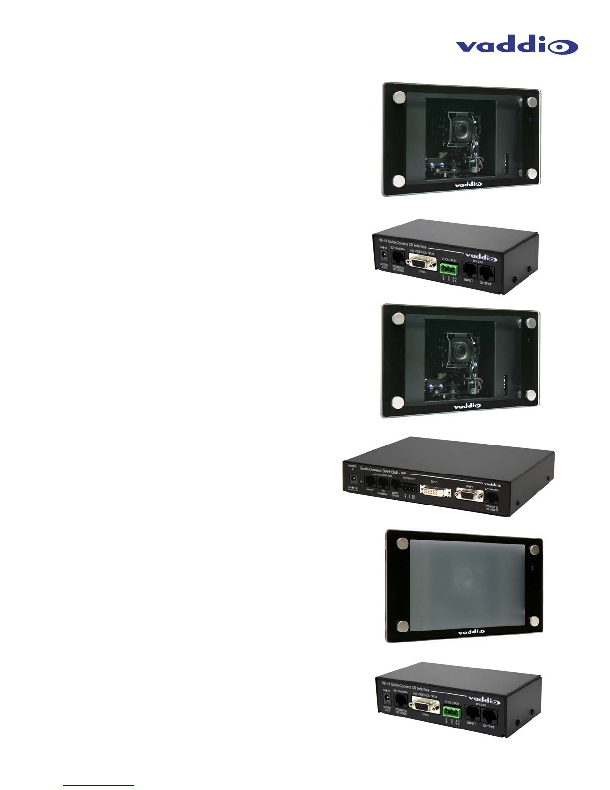
Vaddio’s REVEAL IN-Wall PTZ cameras are the first in Vaddio’s
Architectural Series robotic camera products. The REVEAL was
designed to blend into high-end videoconference and presentation
rooms and the aesthetics match closely to that of flat screen
monitors in shape, color and finish. The REVEAL uses a Smart
Glass technology framing system which when activated, frosts the
front glass frame and shuts off the camera so there is no mistake
that the REVEAL is on or off. This ensures that conference
participants know what state the camera is in (on or off) which is
important in the high-end room system designs.
REVEAL IN-Wall PTZ Smart Glass - Frosted/OFF
The REVEAL Smart Glass is composed of a liquid crystal matrix, laminated between ITO coatings and glass. When the
camera is turned on, the glass switches to its clear state, the camera homes and is ready for use. Vaddio also offers a
clear glass version of the REVEAL system.
Key features include the use of a 1/3-type, 1.3 Megapixel CCD image
sensor for crisp clear images, 1.8 LUX rating and 18X glass optical
zoom lens which works well in small or large rooms and lower light
environments. The REVEAL enclosure uses the depth of the wall
cavity eliminating the cameras extension into the room and the
REVEAL works with the Vaddio HSDS™ cabling standard for video,
power and control over Cat. 5 cabling. The REVEAL looks as good as
it does on the inside as the outside and provides superior HD video
images for wide range of HD applications.
REVEAL IN-Wall PTZ Camera with Clear Glass
Intended Use:
Before operating the system, please read the entire manual thoroughly. The system was designed, built and tested for
use indoors, and with the provided power supply. The use of a power supply other than the one provided or outdoor
operation has not been tested and could damage the camera and/or create a potentially unsafe operating condition.
Save These Instructions:
The information contained in this manual will help you install and operate your system. If these instructions are
misplaced, Vaddio keeps copies of Specifications, Installation, User Guides and the most pertinent product drawings on
the Vaddio website. These documents can be downloaded from www.vaddio.com
free of charge.
Important Safeguards:
Read and understand all instructions before using. Do not operate any device if it has been dropped or damaged. In this
case, a Vaddio technician must examine the product before operating. To reduce the risk of electric shock, do not
immerse in water or other liquids and avoid extremely humid conditions.
Use only the power supply provided with the REVEAL system. Use of
any unauthorized power supply will void any and all warranties.
Please do not use “pass-thru” type RJ-45 connectors. These pass-thru type connectors
do not work well for professional installations and can be the cause of intermittent
connections which can result in the RS-232 control line failing and locking up, and/or
compromising the HSDS™ differential video. For best results please use standard RJ-45
connectors and test all cables for proper pin-out prior to termination.
REVEAL IN-Wall Camera Manual Document Number 342-0059 Rev. A Page 3 of 28
Page 4

REVEAL IN-Wall Cameras
Unpacking:
Carefully remove the complete REVEAL camera assembly and all of the hardware from the packaging. The exploded
view drawing below details the parts included. Please verify that all the parts are included.
1) One(1) REVEAL Camera Module and Enclosure
2) Four (4) Spiral Wall Anchors
3) Four (4) #8-32 x 1.25” Sheet Metal Screws
4) Four (4) 0.5” OD x 0.25” ID x 1.25” White Nylon Spacers
5) One (1) Face Frame Cover for Enclosure
6) Four (4) ¾” OD x ¾” Tall Brushed Aluminum Stand-offs
7) Four (4) ¾” OD Thin (clear) Nylon Washers
8) Four (4) ¼” x 20 x 1.0” Threaded Posts
9) One (1) Glass Plate (either dual pane smart glass or clear glass - depending on the camera ordered
10) Four (4) ¾” OD Nylon Washers with Centering Ridge
11) Four (4) ¾” OD Brushed Aluminum Post Caps
④
②
①
⑥
⑦
③
⑧
⑩
⑤
⑨
⑪
Note: The Smart Glass system is shown.
The Clear Glass REVEAL has a single pane of glass
Packages:
Depending on the package ordered, the contents of the system differ. There are two (2) glass types (Clear and Smart
Glass), (2) Quick-Connect options (HD-18 Quick-Connect SR Interface and Quick-Connect DVI/HDMI SR Interface), two
(2) geographic options (North America and International) and finally an option for the Quick-Connect CCU Controller that
works with any system aforementioned above. The REVEAL product line is flexible with many options. The following
information regarding the contents of each of the packages will cover all the combinations available.
REVEAL IN-Wall Camera Manual Document Number 342-0059 Rev. A Page 4 of 28
Page 5
REVEAL IN-Wall Cameras
Packages (continued):
REVEAL 999-6925-000
One (1) Complete REVEAL Camera Module Assembly (see page 4)
One (1) HD-18 Quick-Connect - SR Interface
One (1) 24VDC, 2.0A PowerRite™ Switching Power Supply
One (1) North American AC Cord Set
One (1) EZCamera Control Adapter
One (1) Vaddio IR Remote Control and Manual
One (1) Installation Guide (342-0059)
- Clear Glass - North America includes:
REVEAL 999-6925-001
One (1) Complete REVEAL Camera Module Assembly (see page 4)
One (1) HD-18 Quick-Connect - SR Interface
One (1) 24VDC, 2.0A PowerRite Power Supply
One (1) Euro AC Cord Set
One (1) UK AC Cord Set
One (1) EZCamera Control Adapter
One (1) Vaddio IR Remote Control and Manual
One (1) Installation Guide (342-0059)
- Clear Glass - International includes:
REVEAL 999-6926-000
One (1) Complete REVEAL Camera Module Assembly (see page 4)
One (1) Quick-Connect DVI/HDMI - SR Interface
One (1) 24VDC, 2.0A PowerRite Switching Power Supply
One (1) North American AC Cord Set
One (1) EZCamera Control Adapter
One (1) Vaddio IR Remote Control and Manual
One (1) Installation Guide (342-0059)
- Clear Glass - North America includes:
REVEAL 999-6926-001
One (1) Complete REVEAL Camera Module Assembly (see page 4)
One (1) Quick-Connect DVI/HDMI - SR Interface
One (1) 24VDC, 2.0A PowerRite Power Supply
One (1) Euro AC Cord Set
One (1) UK AC Cord Set
One (1) EZCamera Control Adapter
One (1) Vaddio IR Remote Control and Manual
One (1) Installation Guide (342-0059)
- Clear Glass - International includes:
REVEAL 999-6935-000
One (1) Complete REVEAL Camera Module Assembly (see page 4)
One (1) HD-18 Quick-Connect - SR Interface
One (1) 24VDC, 2.0A PowerRite™ Switching Power Supply
One (1) North American AC Cord Set
One (1) EZCamera Control Adapter
One (1) Vaddio IR Remote Control and Manual
One (1) Installation Guide (342-0059)
- Smart Glass - North America includes:
REVEAL 999-6935-001
One (1) Complete REVEAL Camera Module Assembly (see page 4)
One (1) HD-18 Quick-Connect - SR Interface
One (1) 24VDC, 2.0A PowerRite Power Supply
One (1) Euro AC Cord Set
One (1) UK AC Cord Set
One (1) EZCamera Control Adapter
One (1) Vaddio IR Remote Control and Manual
One (1) Installation Guide (342-0059)
- Smart Glass - International includes:
HD-18 Quick-Connect - SR Interface
1/3-Rack Size
Quick-Connect DVI/HDMI - SR Interface
1/2-Rack Size
HD-18 Quick-Connect - SR Interface
1/3-Rack Size
REVEAL IN-Wall Camera Manual Document Number 342-0059 Rev. A Page 5 of 28
Page 6

REVEAL IN-Wall Cameras
Packages (continued):
REVEAL 999-6936-000
One (1) Complete REVEAL Camera Module Assembly (see page 4)
One (1) Quick-Connect DVI/HDMI - SR Interface
One (1) 24VDC, 2.0A PowerRite Switching Power Supply
One (1) North American AC Cord Set
One (1) EZCamera Control Adapter
One (1) Vaddio IR Remote Control and Manual
One (1) Installation Guide (342-0059)
- Smart Glass - North America includes:
REVEAL 999-6936-001
One (1) Complete REVEAL Camera Module Assembly (see page 4)
One (1) Quick-Connect DVI/HDMI - SR Interface
One (1) 24VDC, 2.0A PowerRite Power Supply
One (1) Euro AC Cord Set
One (1) UK AC Cord Set
One (1) EZCamera Control Adapter
One (1) Vaddio IR Remote Control and Manual
One (1) Installation Guide (342-0059)
- Smart Glass - International includes:
Quick-Connect DVI/HDMI - SR Interface
1/2-Rack Size
Optional Quick-Connect CCU Controller:
The Quick-Connect CCU controller can be used with any of the REVEAL packages listed above. This CCU Controller
differs from the original Quick-Connect CCU in that it does not provide power to the REVEAL camera, nor does it have the
HSDS™ differential video I/O. The power and video are handled by the HD-18 Quick-Connect - SR Interface and the
Quick-Connect DVI/HDMI - SR Interface. The Quick-Connect CCU Controller works in conjunction with the Control I/O of
each of the SR Interfaces allowing image control including Detail (sharpness) Color (red and blue gain), White Balance
(auto/manual), Iris(auto/manual), Gain, Pedestal, Chroma, Gamma, Knee and allows for three (3) preset scenes
.
Quick-Connect CCU Controller for REVEAL IN-Wall Series Cameras - Front Panel (controls covered later in the manual)
Quick-Connect CCU Controller Rear Panel (I/O and controls covered later in the manual)
The 999-1105-022 System Includes:
One (1) 998-1105-022 Quick-Connect CCU Controller for REVEAL IN-Wall Series Cameras
One (1) 12 VDC, 1.0 Amp Switching Power Supply
One (1) North American AC Cord Set
One (1) Euro AC Cord Set
One (1) UK AC Cord Set
One (1) Manual
REVEAL IN-Wall Camera Manual Document Number 342-0059 Rev. A Page 6 of 28
Page 7

REVEAL IN-Wall Cameras
REVEAL Installation Instructions:
Step 1:
Read this manual before starting the installation. There are several things to consider before
mounting an architectural camera like the REVEAL.
When locating the REVEAL, consider camera and meeting participant viewing angles, lighting conditions, possible line of
site obstructions and check for in-wall obstructions where the camera is to be mounted. Pick a mounting location to
optimize the performance of the camera. Avoid locating lighting elements directly above the REVEAL camera.
The REVEAL system was designed to use the wall cavity of a 2” x 4” (1.5: x 3.5”) stud with a 1/2” to 5/8” drywall. For wall
systems that use a lesser depth stud, a simple extension frame can be fabricated and finished by the integrator or the
owner’s contractors to support the REVEAL system.
Step 2:
Prior to starting work, please review and verify the contents of the system that was purchased (see pages 4 through 6).
Please contact Vaddio Tech Support if any parts are missing. It is difficult to install an incomplete system.
Step 3:
Carefully measure the position of the camera enclosure and mark the drywall accordingly. The size of the wall opening
should be 6.0” tall x 8.75” wide a small ¼” tall notch can be cut in the drywall in order to more easily allow the camera
enclosure to slip into the wall after the Cat. 5 cables are connected (see diagram below). Check the wall for studs before
cutting the drywall. In some cases, part of a stud may require removal and this should be done by qualified personnel.
Use an accurate level to position the enclosure
opening and trace a line to fit the back of the
enclosure leaving a ¼” tall notch above the RJ-45
connectors to help ease the camera inside the wall.
The face frame will cover the ¼” notch.
Cut this area out only after verifying that no studs
or obstructions exist behind the drywall.
Cut the hole to 6.0” tall x 8.75” wide as stated
above.
¼” Tall Notch
Around RJ-45
Connectors
Step 4:
Carefully cut the drywall. Tape the edges of the cut drywall with masking tape to keep the gypsum dust from infiltrating
the camera enclosure and making a dastardly and significant drywall mess.
Ease the camera into the wall opening and
check for fit. Using the level, position the camera enclosure into the hole and mark the holes for the spiral wall anchors
and screws.
Step 5:
Remove the camera enclosure from the wall and install the spiral wall anchors on the marks drawn in Step 4.
REVEAL IN-Wall Camera Manual Document Number 342-0059 Rev. A Page 7 of 28
Page 8

REVEAL IN-Wall Cameras
p
Step 6:
The REVEAL System uses two (2) Cat. 5e cables. One Cat. 5e cable will to power the camera and return HSDS video
signals, and the 2
nd
Cat. 5e cable will handle the RS-232 control signals. Please TEST and label the POWER/VIDEO and
the CONTROL cables accordingly.
On the bottom of the camera, remove the Pan
locking screw as indicated on the right. The
purpose of the screw is to hold down the
pan/tilt mechanism securely during shipment.
Please do not connect power to the REVEAL
before removing the screw
Remove the pan locking
screw prior to connecting
ower to the REVEAL
Route two (2) labeled Cat. 5e cables into the wall cavity and through the opening in the drywall. Plug the POWER/VIDEO
cable into the RJ-45 jack marked EZCAMERA POWER & HD VIDEO and plug the CONTROL RJ-45 into the RS-232 & IR
OUT jack (see below). At the Quick-Connect system, connect the corresponding Cat. 5e cables to the POWER & HD
VIDEO port and the RS-232 OUT port. Please do not cross-connect these cables, instead please label the cables and
avoid the “trial and error” connection technique.
PROPERLY. (Refer to the Switch Settings section for HD video output resolutions and dip switch settings on page 11).
TEST THE CAMERA AT THIS POINT TO ENSURE THE REVEAL WORKS
EZCAMERA
POWER &
HD VIDEO
RS-232 &
IR OUT
Step 7: Ease the Camera Module back into the wall opening with the connected Cat. 5e cables as illustrated below:
Tilt the enclosure and
allow the connectors
to enter the wall
opening before the
bottom of the
enclosure.
Slide the enclosure
straight back into the
wall opening and prior
to securing the camera
to the drywall, pull out
the level….again.
Back-cutting the
drywall and taping the
edges will aid
installation.
REVEAL IN-Wall Camera Manual Document Number 342-0059 Rev. A Page 8 of 28
Page 9

REVEAL IN-Wall Cameras
Step 8:
Insert the four (4) #8-32 x 1.25” sheet metal screws into the previously installed spiral wall anchors but do not tighten
completely. Use the level and adjust the enclosure so that the system is both level and plumb, then tighten the screws.
Trusty & Accurate Level
#8-32 x 1.25” Sheet
Metal Screws X 4
Step 9:
Apply the ½” OD x ¼” ID x 0.125” white nylon spacers over the ¼-20 PEM posts attached to the enclosure’s mounting
flanges.
¼”-20 Post
½” OD x ¼” ID x 1/8”
White Nylon Spacer X 4
Mounting
Flange
STEP 10:
To install the Face Frame Cover, first connect the 4-Wire IR/LED lead with the white connector to the camera control
board and connect the 2-Wire Smart Glass lead with the black connector to the control board as shown.
4-Wire
Rear of Face
Frame Cover
2-Wire
4-Wire White Connector
2-Wire Black
Connector
REVEAL IN-Wall Camera Manual Document Number 342-0059 Rev. A Page 9 of 28
Page 10

REVEAL IN-Wall Cameras
Step 11:
After the connections are made in Step 10, attach the Front Face Cover over the ¼’-20 posts and carefully tuck the extra
wires length of the IR/LED and Smart Glass leads along the side of the circuit boards and behind the vertical cover fins of
the face frame.
¼”-20 Posts
X 4
Remove the
fingerprints on the
frame cover on this
step or the next step
Step 12:
Attach the four (4) ¾” OD x ¾” tall, brushed aluminum stand-offs over the ¼”-20 posts and tighten snuggly by hand.
Screw in the four (4) ¼” x 20 x 1.0” threaded posts into the ¾” brushed aluminum stand-offs with the Allen (hex) wrench
receptacle facing out. Slip the four (4) ¾” OD thin (clear) nylon washers over the threaded posts. The connector for the
Smart Glass is on the circuit board inside the race track shaped front bezel housing on the right hand side of the face
frame cover. See page 11 for rotary and dip switch settings and set the switches to the desired position now.
¾” OD x ¾” tall,
brushed aluminum
stand-offs X 4
Smart Glass
PCB Connector
¾” OD thin
(clear) nylon
washers X 4
¼”-20 x 1”
Posts X 4
(Allen fitting
facing out)
Step 13: For Smart Glass Only
From the back of the Smart Glass, there are two
(2) wires that terminate on a black 2-wire
connector. This cable is connected to the Smart
Glass PCB connector.
NOTE: Skip this step when using the Clear
Glass model (since there are no wires on the
Smart Glass
2-Wire Connector
(from back of
Smart Glass pane)
clear glass).
REVEAL IN-Wall Camera Manual Document Number 342-0059 Rev. A Page 10 of 28
Page 11

REVEAL IN-Wall Cameras
Step 14:
Place the glass over the exposed ¼”-20 posts. The Clear Glass model has a single pane of glass while the Smart Glass
model has a double glass pane with the liquid crystal matrix sandwiched between. The ¼-20 posts can be screwed in all
the way for the Clear Glass, but the Smart Glass, the ¼”-20 posts will need to be screwed out slightly to protrude through
the double pane glass. Put the four (4) ¾” OD nylon washers with centering ridge (ridge toward the camera) and attach
the four (4) ¾” OD brushed aluminum post caps. This concludes the installation of the REVEAL IN-Wall PTZ Camera into
the wall cavity.
Post Cap X 4 with
Nylon Washers with
Centering Ridge X
4 Underneath
16-Position Rotary
Switch for Video
Resolution Selection
and 10-Position Dip
Switch for Functionality
Settings
Camera Switch Settings:
There is a 16-position rotary switch that selects the video output resolution of the REVEAL camera and a 10-position dip
switch that sets other functions such as the IR remote control frequency and test bars on/off. The placement of the Switch
Setting Label is behind the black border masking on the glass pane as shown below.
Front View - Behind Black Border Mask Rear View - Remove Glass to Read and Change Settings as Needed
1080p/30
1080p/25
576i/25 (YPbPr)
9
8
F
A
EDC
B3
VIDEO SELECT
720p/50
1080i/50
1080p/60
1080p/50
720p/59.94
1080p/59.94
480i/29.97 (YPbPr)
1 1080i/59.94
2
765
4
0
10
109
OFF
910
ON
OFF
TEST
BARS
8
7
867768
OFF
OFF
7
6
OFF
OFF
6
OFF
bps
bps
9600
38400
4
4
IR
IR
ON
OFF
OUT
OUT
DIP SWITCH SETTINGS
355
ON
IR 3
IR 3
OFF
2
ON
IR 2
IR 2
OFF
1
ON
IR 1
IR 1
OFF
IR 2
Switch Setting Label:
Set to required settings
in Installation Step 6.
IR 1
OFF
OFF
IR 2
IR 1
ON
ON
1
2
DIP SWITCH SETTINGS
IR
IR 3
OFF
IR 3
ON
355
OUT
OFF
IR
OUT
ON
4
4
9600
bps
38400
bps
6
OFF
68
OFF
OFF
7
7
OFF
OFF
86
8
BARS
OFF
ON
910
TEST
7
6
7
10
OFF
109
0
1
2
3
4
5
6
480i/29.97 (YPbPr)
7
VIDEO SELECT
720p/59.94
1080i/59.94
1080p/59.94
1080p/60
720p/50
1080i/50
1080p/50
8
9
A
B
C
D
E
F
576i/25 (YPbPr)
1080p/30
1080p/25
REVEAL IN-Wall Camera Manual Document Number 342-0059 Rev. A Page 11 of 28
Page 12

REVEAL IN-Wall Cameras
The Quick-Connect Interfaces and Basic Configurations
• HD-18 Quick-Connect SR Interface (used with REVEAL Systems 999-6925-000, 999-6925-001, 999-6935-000 and
999-6935-001):
Rear Panel of the HD-18 Quick-Connect SR Interface (1/3 Rack Width Enclosure)
①
⑤
②
③
④
Connectors:
1) Power Input: 24 VDC, 2.0 Amp Power Connection, 5.5mm OD x 2.5mm ID, Positive Center.
2) EZCamera POWER & HD VIDEO: The Cat. 5e connection supplies 24 VDC power to the REVEAL and returns HSDS differential
video from the camera. Maximum distance on the CAT-5 cable is 100 feet (30.5 m)
3) HD VIDEO OUTPUT: DE-15F (15-pinHD) connector outputs the YPbPr analog component video from the REVEAL camera.
Note: The REVEAL also puts out SD video (480i/30fps & 576i/25fps) in YPbPr analog component format.
4) IR OUTPUT Ports: With the IR pass-thru function (IR OUT) turned on at the camera (see Camera Switch Settings section), it is
possible to send IR from third-party IR remote controls to third-party equipment, such as videoconferencing codecs. IR can be
output as either modulated (for IR Probe) or non-modulated (direct connection) signals for added flexibility in codec connection.
5) RS-232 Input & Output RJ-45 Jacks: The RS-232 INPUT RJ-45 accepts signals from controllers and the RS-232 OUTPUT is
connected to the camera, although this port can be bypassed when not using 3rd party IR remotes. When using the IR pass-thru
function, the IR signals are pulled from the REVEAL from the RS-232 Output Cat. 5e cable.
System Connectivity Example: Featuring the REVEAL Camera, HD-18 Quick-Connect SR Interface & Precision Camera Controller.
REVEAL IN-Wall
Camera System
RS-232
Power to Camera
HD Video from REVEAL
Two (2) - Cat. 5e Cables
Up to 100’ (30.48m)
RS-232
HD Monitor*
RS-232
YPbPr
Resolution
Set at Camera
*Simulated Video Feed
Vaddio ProductionVIEW Precision Camera
Controller
REVEAL IN-Wall Camera Manual Document Number 342-0059 Rev. A Page 12 of 28
Page 13

REVEAL IN-Wall Cameras
r
• Quick-Connect DVI/HDMI - SR Interface (used with REVEAL SYSTEMS 999-6926-000, 999-6926-001, 999-6936-000
and 999-6936-001):
Rear Panel of the Quick-Connect DVI/HDMI - SR Interface (1/2 Rack Width Enclosure)
Connectors:
1) Vaddio Blue LED Power Indicator: Illuminates when the 24 VDC Power supply is plugged in.
2) Power Input: 24 VDC, 2.0 Amp Power Connection, 5.5mm OD x 2.5mm ID, Positive Center.
3) RS-232 INPUT: Connect to joystick controller, codec or control system to control the REVEAL Camera.
4) TO CAMERA: RS-232 Control to & from the Camera and IR signals returned from the camera.
5) DAISY CHAIN Control Port: Daisy Chain Control Emulation (DCCE) output to next Quick-Connect DVI/HDMI for use when daisy
6) IR OUTPUT Ports: With the IR pass-thru function (IR OUT) turned on at the camera (see Camera Switch Settings section), it is
7) DVI-D Output: High Definition Multimedia Interface (HDMI) Transmitter, HDMI (v 1.3 with deep color) and DVI v 1.0 Compliant,
8) YPbPr Output: DE-15F (15-pinHD) connector outputs the YPbPr analog component video from the REVEAL camera. Note:
9) EZCamera POWER & HD VIDEO Port: Supplies power to camera and returns HD video from the camera via Cat-5e. Maximum
System Connectivity Example 1: Featuring the REVEAL Camera, Quick-Connect DVI/HDMI SR Interface, Preview Monitors and
Precision Camera Controller.
①
②
chain control lines can’t be avoided.
possible to send IR from third-party IR remote controls to third-party equipment, such as videoconferencing codecs. IR can be
output as either modulated (for IR Probe) or non-modulated (direct connection) signals for added flexibility in codec connection.
Resolutions up to 1080p/60 are supported.
The REVEAL also puts out SD video (480i/30fps & 576i/25fps) in YPbPr analog format. Resolutions up to 1080p/60 with monitor
support are possible.
distance on the CAT-5e cable is 100’ (30.5 m).
③
④⑤ ⑥
⑦
⑨⑧
Power to Camera
HD Video from Camera
REVEAL IN-Wall
Camera System
Two (2) - Cat. 5e Cables
Up to 100’ (30.48m)
Quick-Connect
DVI/HDMI - SR
Interface
RS-232 Control
RS-232
REVEAL IN-Wall Camera Manual Document Number 342-0059 Rev. A Page 13 of 28
Vaddio ProductionVIEW™
Precision Camera Controller
DVI-D
DVI or HDMI - Large Format
Monitor or Projector*
YPbP
Vaddio PreVIEW™ HD 7.0 Rack Monitors*
*Simulated Video Feeds
Page 14

REVEAL IN-Wall Cameras
S-23
S-232 &
Simulated
deo Fe
eds
System Connectivity Example 2:
Advanced videoconferencing solution featuring two (2) Vaddio REVEAL cameras, Quick-Connect DVI/HDMI - SR
Interfaces, configured with single control port codec (C60) with Daisy Chain Control Emulation (DCCE) and IR forwarded
through the main REVEAL camera to the codec via IR emitter.
Codec IR Remote:
Forwarded through
Main Camera for
Codec Control
Main Camera
REVEAL IN-Wall PTZ Camera Systems
Camera 2
Monitor 1
Quick-Connect
DVI/HDMI SR
Interface #1
RS-232
DVI to HDMI
Cable
HD Video Monitors*
*
Vi
R
DVI-D HDMI
IR
Probe
IR Return
DVI Cable
DVI Cable
Monitor 2
Power to Camera,
HD Video from Camera
Two (2) Cat. 5e
Cables - up to
100’ (30.48m)
RS-232 Cat. 5e
Daisy Chain Link between
Quick-Connect Interfaces
Single RS-232 Port Codec with
Daisy Chain Camera Control
Microphones
Two (2) Cat. 5e
Cables - up to
100’ (30.48m)
R
2
Quick-Connect
DVI/HDMI SR
Interface #2
Computer with
DVI Output
ETHERNET
C60 Codec
REVEAL IN-Wall Camera Manual Document Number 342-0059 Rev. A Page 14 of 28
Page 15

REVEAL IN-Wall Cameras
Optional Quick-Connect CCU Controller:
The Quick-Connect CCU controller can be used with any of the REVEAL packages. To review, this CCU Controller
differs from the original Quick-Connect CCU in that it does not provide power to the REVEAL camera, nor does it have the
HSDS™ differential video I/O. The power and video are handled by the HD-18 Quick-Connect - SR Interface or the
Quick-Connect DVI/HDMI - SR Interface. The following section will outline the functions of the front panel controls and
the rear panel connectivity.
Front Panel Controls (left to right):
Tally Light:
The blue LED tally light on the front panel is tied to the tally contacts on the rear panel allowing the user to easily track
which camera interface is being used in a multi-camera system by supplying a simple contact closure (i.e. from
ProductionVIEW Precision Camera Controller or ProductionVIEW HD).
LCD Display:
Backlit (blue) display indicates which parameter (iris, detail, etc.) is being adjusted. When a rotary encoder is moved, the
name of the control being adjusted and the value of that assigned parameter will be displayed.
Scenes A, B & C:
Three camera adjustment scenes (A, B & C) can be stored into microprocessor memory. When lit (backlit blue SPDT
Button), the scene is activated. To store a scene, the user adjusts the controls and touches and holds the scene button
down until the button blinks.
Detail:
The Detail control sharpens or softens objects in the frame.
Red & Blue Gain Controls:
The Red and Blue Gain encoders adjust the red and blue gain of the signal when AWB is disengaged.
AWB:
The Automatic White Balance controls/adjusts the color levels automatically when engaged. Turn off AWB to manually
adjust the Red and Blue levels, as well as Red, Green and Blue Enhance.
SHIFT:
Pressing Shift illuminates the button and changes the Pedestal adjustment knob to Knee adjustment. Knee adjustment
allows bright objects that are easily overexposed to be reproduced more accurately. Pressing the Shift button a second
time turns the light off, and the knob reverts to Pedestal adjustment.
Pedestal / Knee, Chroma & Gamma:
The Pedestal adjustment controls the absolute black level of an image. Chroma controls the overall color of the image
being captured. Gamma adjusts the overall brightness of an image. See SHIFT for information on Knee.
Auto Iris:
The Auto Iris mode automatically adjusts the iris and gain of the camera. To manually adjust the iris or gain, turn off this
control.
Manual Iris:
The manual iris control allows the user to set the iris manual to one of the 18 settings available.
Gain:
The Gain control boosts the signal level when the iris is open all the way, and there is not enough lighting available. To
manually adjust the gain Auto Iris must be off.
REVEAL IN-Wall Camera Manual Document Number 342-0059 Rev. A Page 15 of 28
Page 16

REVEAL IN-Wall Cameras
Rear Panel Connectivity (left to right):
Power Input:
5.5mm OD x 2.5mm ID, Positive Center 12 VDC, 1.0 Amp, Power Jack
Use with Provided 12 VDC, 1.0 Amp Power supply only.
RS-232 IN:
Control input from Joystick Controller (i.e. Precision Camera Controller, ProductionVIEW HD, etc…), control system or
codec. This input provides for camera control other than CCU controls.
RS-232 OUT (To Camera):
Attach to REVEAL camera RS-232 Port for CCU Control. The IR OUT, IR Forwarding feature is not processed by the
CCU Controller.
Tally Contact:
Local front panel tally - lights up Blue LED on front panel when shorted.
Camera Settings:
10-position dip switch for added functions and future control parameters.
Instructions for using the Quick-Connect CCU Controller with the REVEAL Camera:
• Power Up Order: When using the Quick-Connect CCU, power up the REVEAL camera first, then the Quick-Connect
CCU. The Quick-Connect CCU and ProductionVIEW Controllers will auto-detect the camera attached, so naturally
the REVEAL has to be ON first.
• Monitor Set Up: Verify that the video monitor used in conjunction with the Quick-Connect CCU is set up correctly
and is delivering accurate color reproduction.
• Initial CCU Set Up: Adjust the iris level of the camera so that brighter areas are not washed out. Then adjust the
Pedestal level so that the black levels are not too dark, and not too light. When those levels are set, adjust the Red &
Blue Gain, Gamma, Detail, Knee and Chroma. NOTE: Gain (next to Iris) should be left at 0 (zero), unless lighting is
inadequate, then turn it to a level where the signal brightness is at an appropriate level. Higher Gain levels add
additional noise (grain) to the video signal.
• IR Output Switch 4: When operating the REVEAL camera connected directly to the Quick-Connect CCU, set the IR
Output dip switch on the front of the REVEAL to the OFF position. If it is not turned off, it may interfere with proper
operation of the PTZ camera.
See the next page for a system configuration diagram using the SR Series Interfaces with the CCU controller.
REVEAL IN-Wall Camera Manual Document Number 342-0059 Rev. A Page 16 of 28
Page 17

REVEAL IN-Wall Cameras
System Connectivity Example: Featuring the REVEAL Camera, HD-18 Quick-Connect SR Interface, REVEAL Series Quick-Connect
CCU Controller & ProductionVIEW HD
REVEAL IN-Wall
Camera System
RS-232
Power to Camera - HSDS Video from REVEAL
RS-232
Two (2) - Cat. 5e Cables
Up to 100’ (30.48m)
HD-18
Quick-Connect SR
Interface
YPbPr
RS-232
REVEAL Series Quick-Connect CCU
Vaddio ProductionVIEW HD
PREVIEW
YPbPr or SD
or RGBHV
PROGRAM
HD
Monitors*
*Simulated Video Feeds
REVEAL IN-Wall Camera Manual Document Number 342-0059 Rev. A Page 17 of 28
Page 18

REVEAL IN-Wall Cameras
Vaddio IR Remote Commander
The REVEAL camera uses the standard Vaddio IR Remote Commander. Selection of the
remote frequency can be performed through a dip switch setting on the REVEAL. The IR
remote can transmit up to 3 different sets of IR codes allowing the use and IR control of 3
REVEAL cameras in a room.
The following functions are accessible with the Vaddio remote:
• Camera Power On/Off (Toggle on/off same button)
• Back Light Compensation (Toggle on/off same button)
• Camera Select for Remote: The remote can operate three (3) cameras
• Pan/Tilt and Home controls with Reverse and Std. Pan direction
• Pan/Tilt Reset
Vaddio
IR Remote
Commander
• Auto Focus (Toggle on/off same button)
• Data Screen (Toggles the Smart Glass version - frosted to clear)
• Zoom In/Out controls Wide & Telephoto
Fast speed controls (W & T)
Slow speed controls (W & T)
• Manual Focus On/Off control (Toggle on/off same button)
Near (-) adjustment
Far (+) adjustment
• Six (6) pan/tilt/zoom positioning presets (1 through 6)
• Preset Set (store)
• Preset Reset (clear)
Connectors and Pin-out Detail:
The connections on the top of the camera enclosure are as follows:
1) One (1) RJ-45 connector for RS-232 communication and IR Out
2) One (1) RJ-45 connector for Power/Video for the Quick-Connect HD-18 - SR or Quick-Connect DVI/HDMI - SR.
RS-232/IR Out RJ-45:
This jack provides for RS-232 bi-directional control and IR Out for IR Forwarding of 3
codecs.
Pin Function
1) Unused
2) Unused
3) Unused
4) IR Output (Diff Signal to Quick-Connect)
5) IR Ground (Diff Signal to Quick-Connect)
12345678
6) GND
7) RXD (from TXD of control source)
8) TXD (to RXD of control source)
Power/Video RJ-45:
The Power/Video Port supplies power to the REVEAL and returns HSDS (differential HD Video) up to 100’ (30.5m).
Pin Function
1) Power+
2) Power-
3) Y+
4) PB+
5) PB GND
12345678
6) Y GND
7) PR+
8) PR-
rd
party IR Remotes to control
REVEAL IN-Wall Camera Manual Document Number 342-0059 Rev. A Page 18 of 28
Page 19

REVEAL IN-Wall Cameras
Switch Settings Detail:
There are user accessible rotary and dip switches to select video resolution
and other functions as well. The switches are as follows:
• 16-Position Rotary Switch with Detents for HD Video Selection:
The REVEAL camera has user selectable video output resolution. The
video resolutions are selected via the 16-position rotary switch (right)
which is accessible from the front of the REVEAL camera.
The video resolution assignments are as follows:
Position Resolution
0 720p/59.94
1 1080i/59.94
2 1080p/59.94
Accessible
Switch Gear
3 1080p/60
4 720p/50
5 1080i/50
6 1080p/50
7 480i/29.97 (YPbPr - component video)
16-Position
Rotary Switch
8 576i/25 (YPbPr - component video)
9 Unused/Future
A
B
C
D
---
---
---
---
E 1080p/30
F 1080p/25
• 10-position Dip Switch
The REVEAL has a 10-position dip switch accessible on the front of the camera for IR frequency selection, and other
control functions. The accessible functions are listed below:
Functions:
Position Resolution
1 IR Freq 1 - On/Off
2 IR Freq 2 - On/Off
10-Position Dip Switch
Accessible from the front
of the REVEAL camera
without the glass in place
3 IR Freq 3 - On/Off
4 IR Out - On/Off
5 Control Speed - 9600 or 38400
6 Unused
7 Unused
UP -↑
DOWN -
↓
8 Unused
9 Test Bars - On/Off
10 Unused
REVEAL IN-Wall Camera Manual Document Number 342-0059 Rev. A Page 19 of 28
Page 20

REVEAL IN-Wall Cameras
GENERAL SPECIFICATIONS:
REVEAL IN-Wall Camera Systems
Part Numbers
• Camera Characteristics
Image Device
Picture Elements
Video Resolutions
Lens
Focal Length
Horizontal Viewing Angle
Frame Delay
Video S/N Ratio
Invertible
Minimum Illumination
Control Protocol
Serial Communication
Pan Range
Tilt Range
Preset Positions
• Quick-Connect Systems (Quick-Connect DVI/HDMI SR Interface and HD-18 Quick-Connect SR Interface)
YPbPr Support
(Analog Component)
DVI-D/HDMI and YPbPr
Support
(Digital - DVI-D and HDMI
with adapter cable and
Analog Component)
Cat. 5e Cable Distance
Power Supply
Dimensions
• REVEAL Module Characteristics
Glass Properties
Power Consumption
Connectors
Dimensions (H x W x D)
Weight
• Optional Quick-Connect CCU Controller for REVEAL Series Cameras
Connectors
Controls
Dimensions
999-6925-000 - Clear Glass - HD-18 Quick-Connect SR Interface - North American Version
999-6925-001 - Clear Glass - HD-18 Quick-Connect SR Interface - International Version
999-6926-000 - Clear Glass - Quick-Connect DVI/HDMI SR Interface - North American Version
999-6926-001 - Clear Glass - Quick-Connect DVI/HDMI SR Interface - Euro & UK Cord Set
999-6935-000 - Smart Glass - HD-18 Quick-Connect SR Interface - North American Version
999-6935-001 - Smart Glass - HD-18 Quick-Connect SR Interface - International Version
999-6936-000 - Smart Glass - Quick-Connect DVI/HDMI SR Interface - North American Version
999-6936-001 - Smart Glass - Quick-Connect DVI/HDMI SR Interface - International Version
Option 999-1105-022 - Quick-Connect CCU Controller for REVEAL
1/3-type CCD Sensor
1.3 Megapixel
720p-59.94/50, 1080i-59.94/50, 1080p-60/59.94/50/30/25, 480i/30fps, 576i/25fps
18x Optical Zoom
f=4.7 to 84.6mm
3.2 to 55.2 degrees (16:9)
1 frame
>50 dB
Yes
1.8 Lux
VISCA
RS-232 (9600 or 38,400)
140 degrees (+ 70 degrees)
+25 degrees to -40 degrees
16 (internal), 6 recalled via IR Remote
HD-18 Quick-Connect SR Interface
Power Connector: 5.5mm OD x 2.5mm ID, Positive Center
Control In RJ-45: Accepts RS-232 from ProductionVIEW or other non-daisy-chain control systems
Control Out RJ-45: To REVEAL Camera
Video RJ-45: Transports power to REVEAL and return HSDS video from camera
YPbPr Out: DE-15F Connector, Resolution set at camera
1/3-Rack Size - Accessory Rack Panel Option: 998-6000-002
Quick-Connect DVI/HDMI SR Interface
Power Connector: 5.5mm OD x 2.5mm ID, Positive Center
Control In RJ-45: Accepts RS-232 from ProductionVIEW or other non-daisy-chain control systems
Control Out RJ-45: To REVEAL Camera
Video RJ-45: Transports power to REVEAL and return HSDS video from camera
YPbPr Out: DE-15F Connector, Resolution set at camera
DVI-D Out: HDMI (v1.3 with deep color) Transmitter and DVI v1.0 Compliant, Resolutions up to 1080p/60 supported
DCCE - Daisy Chain Control Emulation Port: RJ-45 Connector
1/2-Rack Size - Accessory Rack Panel Option: 998-6000-003
Up to 100’ (30.5m) for Video, Power and Control
24 VDC, 2.0 Amp PowerRite Power Supply included with AC Cord Sets
1-RU Rack Mount - 1.72” H x 19” W x 6” D (4.45 cm x 4.26 cm x 15.24 cm)
The REVEAL Smart Glass is composed of a liquid crystal matrix, laminated between ITO (Indium tin oxide) layers and glass.
When a charge is applied to the opaque glass, the glass becomes transparent.
The REVEAL Clear Glass model uses clear glass.
500mA in stand-by frosted opaque mode, 550mA in clear glass camera on mode
Two (2) RJ-45 on top of camera enclosure: One (1) for Power and HSDS Video, One (1) for Control
IN-Wall section of back box: 5.75” (146mm) H x 8.5” (216mm) W x 3.85” (98mm) D,
Wall cut out dimensions: 6” (152.4mm) H x 8.75” (222.25) W
Outer Frame Size: 6.75”(171.5mm) H x 11.75” (298.5mm) W
Glass Dimensions: 7.1875” (182.56mm) H x 12.75” (323.85mm) W x 0.4125” D (Clear Glass, 0.5” D (Smart Glass)
Glass Offset from wall: 1.25” (31.75mm)
8.55 lbs. (3.878214763500001 kg, roughly)
Power Connector: 5.5mm OD x 2.5mm ID, Positive Center
Control In RJ-45: Accepts RS-232 from ProductionVIEW or other non-daisy-chain control systems
Control Out RJ-45: To REVEAL Camera
Tally: 2-Pin Phoenix type connector
Video RJ-45: Transports power to REVEAL and return HSDS video from camera
3-Preset Scenes, Detail, AWB, Red Gain, Blue Gain, Pedestal, Knee, Chroma, Gamma, Iris (Auto/Manual), Gain
1-RU Rack Mount - 1.72” H x 19” W x 6” D (4.45 cm x 4.26 cm x 15.24 cm)
REVEAL IN-Wall Camera Manual Document Number 342-0059 Rev. A Page 20 of 28
Page 21

REVEAL IN-Wall Cameras
Compliance and CE Declaration of Conformity - REVEAL IN-Wall Camera Systems and HD-18 Quick- Connect SR
Interface
FCC Part 15 Compliance
This equipment has been tested and found to comply with the limits for a Class A digital device, pursuant to Part 15 of the
FCC Rules. These limits are designed to provide reasonable protection against harmful interference when the equipment
is operated in a commercial environment. This equipment generates, uses, and can radiate radio frequency energy and, if
not installed and used in accordance with the instruction manual, may cause harmful interference to radio
communications. Operation of this equipment in a residential area is likely to cause harmful interference in which case the
user will be required to correct the interference at his/her own expense.
Operation is subject to the following two conditions: (1) This device may not cause interference, and (2) This device must
accept any interference including interference that may cause undesired operation of the device.
Changes or modifications not expressly approved by Vaddio can affect emission compliance and could void the user’s
authority to operate this equipment.
ICES-003 Compliance
This digital apparatus does not exceed the Class A limits for radio noise emissions from digital apparatus set out in the
Radio Interference Regulations of the Canadian Department of Communications.
Le présent appareil numérique n’emet pas de bruits radioélectriques dépassant les limites applicables aux appareils
numeriques de la classe A préscrites dans le Règlement sur le brouillage radioélectrique édicte par le ministère des
Communications du Canada.
European Compliance
This product has been evaluated for Electromagnetic Compatibility under the EMC Directive for Emissions and Immunity and meets the
requirements for a Class A digital device. In a domestic environment this product may cause radio interference in which case the user
may be required to take adequate measures.
Standard(s) To Which Conformity Is Declared:
EMC Directive 2004/108/EC
EN 55022 A: 2006 + A1 2007 (CISPR 22:2005/A1:2005) Conducted and Radiated Emissions
EN 55024: 1998 + Amendments A1: 2001 + A2: 2003 - Electromagnetic Compatibility - Immunity
EN 61000-4-2: 1995 + Amendments A1: 2001 + A2: 2003 - Electrostatic Discharge
EN 61000-4-3: 2006 - Radiated Immunity
EN 61000-4-4: 2004 + Corrigendum 2006 - Electrical Fast Transients
EN 61000-4-5: 2006 - Surge Immunity
EN 61000-4-6: 2007 - Conducted Immunity
EN 61000-4-8: 1993 +Amendment A1: 2001 - Power Frequency Magnetic Field
EN 61000-4-11: Second Edition: 2004 -Voltage Dips, Interrupts and Fluctuations
REVEAL IN-Wall Camera Manual Document Number 342-0059 Rev. A Page 21 of 28
Page 22

REVEAL IN-Wall Cameras
Compliance and CE Declaration of Conformity - Quick-Connect DVI/HDMI SR Interface
FCC Part 15 Compliance
This equipment has been tested and found to comply with the limits for a Class A digital device, pursuant to Part 15,
Subpart B, of the FCC Rules. These limits are designed to provide reasonable protection against harmful interference
when the equipment is operated in a commercial environment. This equipment generates, uses, and can radiate radio
frequency energy and, if not installed and used in accordance with the instruction manual, may cause harmful interference
to radio communications. Operation of this equipment in a residential area is likely to cause harmful interference in which
case the user will be required to correct the interference at his/her own expense.
Operation is subject to the following two conditions: (1) This device may not cause interference, and (2) This device must
accept any interference including interference that may cause undesired operation of the device.
Changes or modifications not expressly approved by Vaddio can affect emission compliance and could void the user’s
authority to operate this equipment.
ICES-003 Compliance
This digital apparatus does not exceed the Class A limits for radio noise emissions from digital apparatus set out in the
Radio Interference Regulations of the Canadian Department of Communications.
Le présent appareil numérique n’emet pas de bruits radioélectriques dépassant les limites applicables aux appareils
numeriques de la classe A préscrites dans le Règlement sur le brouillage radioélectrique édicte par le ministère des
Communications du Canada.
European Compliance
This product has been evaluated for Electromagnetic Compatibility under the EMC Directive for Emissions and Immunity
and meets the requirements for a Class A digital device. In a domestic environment this product may cause radio
interference in which case the user may be required to take adequate measures.
Standard(s) To Which Conformity Is Declared:
EMC Directive 2004/108/EC
EN 55022 A: 2006 + A1 2007 (CISPR 22:2005/A1:2005) Conducted and Radiated Emissions
EN 55024: 1998 + Amendments A1: 2001 + A2: 2003 - Electromagnetic Compatibility - Immunity
EN 61000-4-2 Electrostatic Discharge
EN 61000-4-3 Radiated Immunity
EN 61000-4-4 Electrical Fast Transients
EN 61000-4-5 Surge Immunity
EN 61000-4-6 Conducted Immunity
EN 61000-4-8 Power Frequency Magnetic Field
EN 61000-4-11 Voltage Dips, Interrupts and Fluctuations
To comply with the EMC Directive, it is recommended that the supplied ferrite cylinders are applied to the cables as described below:
• One (1) Laird Technologies 28A2432-0A2 Clamp-on Ferrite Cylinder (If using the IR Forwarding Function, wrap IR forwarding LED wires twice
before screwing stripped wire ends to 3 conductor Molex 5.0mm Euro Jack)
• Two (2) Laird Technologies 28A0640-0A2 Clamp-on Ferrite Cylinder (Clamp around 0.8" diameter shielded DVI cable at the Quick-Connect end)
• One (1) Laird Technologies HFA163090-0A2 Clamp-on Ferrite Cylinder (Clamp around 0.8" diameter shielded DVI Cable at the Monitor end).
REVEAL IN-Wall Camera Manual Document Number 342-0059 Rev. A Page 22 of 28
Page 23

REVEAL IN-Wall Cameras
Compliance and CE Declaration of Conformity - Quick-Connect CCU Controller for REVEAL Series Cameras
FCC Part 15 Compliance
This equipment has been tested and found to comply with the limits for a Class A digital device, pursuant to Part 15 of the
FCC Rules. These limits are designed to provide reasonable protection against harmful interference when the equipment
is operated in a commercial environment. This equipment generates, uses, and can radiate radio frequency energy and, if
not installed and used in accordance with the instruction manual, may cause harmful interference to radio
communications. Operation of this equipment in a residential area is likely to cause harmful interference in which case the
user will be required to correct the interference at his/her own expense.
Operation is subject to the following two conditions: (1) This device may not cause interference, and (2) This device must
accept any interference including interference that may cause undesired operation of the device.
Changes or modifications not expressly approved by Vaddio can affect emission compliance and could void the user’s
authority to operate this equipment.
ICES-003 Compliance
This digital apparatus does not exceed the Class A limits for radio noise emissions from digital apparatus set out in the
Radio Interference Regulations of the Canadian Department of Communications.
Le présent appareil numérique n’emet pas de bruits radioélectriques dépassant les limites applicables aux appareils
numeriques de la classe A préscrites dans le Règlement sur le brouillage radioélectrique édicte par le ministère des
Communications du Canada.
European Compliance
This product has been evaluated for Electromagnetic Compatibility under the EMC Directive for Emissions and Immunity
and meets the requirements for a Class A digital device. In a domestic environment this product may cause radio
interference in which case the user may be required to take adequate measures.
Standard(s) To Which Conformity Is Declared:
EMC Directive 89/336/EEC
EN 55022A: September 1998, A1 October 2000 - Conducted and Radiated Emissions
EN 55024: 1998 + Amendment A1: 2001 - Electromagnetic Compatibility - Immunity
EN 61000-4-2 Electrostatic Discharge Requirements
EN 61000-4-3 Radiated Electromagnetic Field Requirement
EN 61000-4-4 Electrical Fast Transients / Burst Requirements
EN 61000-4-5 Surge Requirements
EN 61000-4-6 Conducted Immunity Requirements
EN 61000-4-8 Power Frequency Magnetic Field Requirements
EN 61000-4-11 Voltage Dips, Interrupts and Fluctuations Requirements
REVEAL IN-Wall Camera Manual Document Number 342-0059 Rev. A Page 23 of 28
Page 24

REVEAL IN-Wall Cameras
Warranty Information:
Hardware* Warranty - One year limited warranty on all parts. Vaddio warrants this product against defects in materials
and workmanship for a period of one year from the day of purchase from Vaddio. If Vaddio receives notice of such
defects during the warranty period, they will, at their option, repair or replace products that prove to be defective.
Exclusions - The above warranty shall not apply to defects resulting from: improper or inadequate maintenance by the
customer, customer applied software or interfacing, unauthorized modifications or misuse, operation outside the normal
environmental specifications for the product, use of the incorrect power supply, improper extension of the power supply
cable or improper site operation and maintenance.
Vaddio Customer Service – Vaddio will test, repair, or replace the product or products without charge if the unit is under
warranty and is found to be defective. If the product is out of warranty, Vaddio will test then repair the product or products.
The cost of parts and labor charge will be estimated by a technician and confirmed by the customer prior to repair. All
components must be returned for testing as a complete unit. Vaddio will not accept responsibility for shipment after it has
left the premises.
Vaddio Technical Support - Vaddio technicians will determine and discuss with the customer the criteria for repair costs
and/or replacement. Vaddio Technical Support can be contacted through one of the following resources: e-mail support at
support@vaddio.com or online at www.vaddio.com
.
Return Material Authorization (RMA) Number - Before returning a product for repair or replacement, request an RMA
from Vaddio’s technical support. Provide a technician with a return phone number, e-mail address, shipping address, and
product serial numbers and describe the reason for repairs or returns as well as the date of purchase and proof of
purchase. Include your assigned RMA number in all correspondence with Vaddio. Write your assigned RMA number on
the outside of the box when returning the product.
Voided Warranty – The warranty does not apply if the original serial number has been removed or if the product has
been disassembled or damaged through misuse, accident, modifications, or unauthorized repair. Cutting the power
supply cable on the secondary side (low voltage side) to extend the power to the device (camera or controller) voids the
warranty for that device.
Shipping and Handling - Vaddio will not pay for inbound shipping transportation or insurance charges or accept any
responsibility for laws and ordinances from inbound transit. Vaddio will pay for outbound shipping, transportation, and
insurance charges for all items under warranty but will not assume responsibility for loss and/or damage by the outbound
freight carrier.
• If the return shipment appears damaged, retain the original boxes and packing material for inspection by the carrier.
Contact your carrier immediately.
Products not Under Warranty - Payment arrangements are required before outbound shipment for all out of warranty
products.
*Vaddio manufactures its hardware products from parts and components that are new or equivalent to new in accordance with industry standard practices.
Other General Information:
Care and Cleaning
Do not attempt to take this product apart at any time. There are no user-serviceable components inside.
• Do not spill liquids in the REVEAL.
• Keep this device away from food and liquid.
• For smears or smudges on the console, wipe with a clean, soft cloth with a light duty household cleaner,
“Windex®” type that leaves no residue.
• Do not use any abrasive chemicals.
Operating and Storage Conditions:
Do not store or operate the REVEAL under the following conditions:
• Temperatures above 40°C (104°F) or temperatures below 0°C (32°F)
• High humidity, condensing or wet environments or In inclement weather
• Dusty environments
• In outer space or in a swimming pool
• Under severe vibration
REVEAL IN-Wall Camera Manual Document Number 342-0059 Rev. A Page 24 of 28
Page 25

REVEAL IN-Wall Cameras
Communication Specification:
• Communication Speed: 9600 bps (default)
• Start bit: 1
• Stop bit: 1
• Data bits: 8
• Parity: None
• No Flow control
NOTE: The Vaddio REVEAL Control Protocol is similar, but not identical to the Sony
®
VISCA™ command set in order to
be compatible with several popular control devices and codecs. Not all VISCA commands are supported and there are
many REVEAL specific commands in the following Command and Inquiry Lists.
HD-18 Command List (1/2)
Command Set V Command Command Packet Comments
AddressSet Y Broadcast 88 30 01 FF Address Set
IF_Clear Y Broadcast 88 01 00 01 FF I/F Clear
CommandCancel Y 81 2p FF p: Socket No(=1 to2)
CAM_Power Y
CAM_Zoom Y
CAM_Focus Y
CAM_WB Y
CAM_RGain Y
CAM_BGain Y
CAM_AE Y
CAM_Iris Y
CAM_Gain Y
On
Y
Off
Stop
Tele(Standard)
Y
Wide(Standard)
Y
Tele(Variable)
Y
Wide(Variable)
Y
Direct
Y
Direct(Variable)
Y
Stop
Far(Standard)
Y
Near(Standard)
Y
Far(Variable)
Y
Near(Variable)
Y
AutoFocus
Y
ManualFocus
Y
Auto/Manual
Y
Auto
Y
Manual
Reset
Up
Y
Down
Y
Direct
Y
Reset
Up
Y
Down
Y
Direct
Y
Full Auto
Y
Manual
Shutter Priority
Y
Iris Priority
Y
Bright
Y
Reset
Up
Y
Down
Y
Direct
Y
Reset
Up
Y
Down
Y
Direct
Y
81 01 04 00 02 FF
81 01 04 00 03 FF
81 01 04 07 00 FF
81 01 04 07 02 FF
81 01 04 07 03 FF
81 01 04 07 2p FF
81 01 04 07 3p FF
81 01 04 47 0p 0q 0r 0s FF
81 01 7E 01 4A 0V 0p 0q 0r 0s FF
81 01 04 08 00 FF
81 01 04 08 02 FF
81 01 04 08 03 FF
81 01 04 08 2p FF
81 01 04 08 3p FF
81 01 04 38 02 FF
81 01 04 38 03 FF
81 01 04 38 10 FF
81 01 04 35 00 FF
81 01 04 35 05 FF
81 01 04 03 00 FF
81 01 04 03 02 FF
81 01 04 03 03 FF
81 01 04 43 00 0p 0q 0r FF
8x 01 04 04 00 FF
8x 01 04 04 02 FF
81 01 04 04 03 FF
81 01 04 44 00 0p 0q 0r FF
81 01 04 39 00 FF
81 01 04 39 03 FF
81 01 04 39 0A FF
81 01 04 39 0B FF
81 01 04 39 0D FF
81 01 04 0B 00 FF
81 01 04 0B 02 FF
81 01 04 0B 03 FF
81 01 04 4B 00 00 0p 0q FF
81 01 04 0C 00 FF
81 01 04 0C 02 FF
81 01 04 0C 03 FF
81 01 04 4C 00 00 0p 0q FF
Power On/Off
p:0(Slow) to 7(Fast)
p:0(Slow) to 7(Fast)
pqrs: Zoom Position*
V:(Speed) 0-7
Supported as ‘Standard’
Supported as ‘Standard’
pqr:000-1ff
pqr:000-1ff
Auto Exposure Mode
Manual Control Mode
Shutter Priority Mode
Exposure Priority Mode (default)
AGC Priority Mode
pq(0x00-0x11)
pq(0x00-0x1E)
REVEAL IN-Wall Camera Manual Document Number 342-0059 Rev. A Page 25 of 28
Page 26

REVEAL IN-Wall Cameras
REVEAL Command List (2/2)
Command Set V Command Command Packet Comments
CAM_Backlight Y Y On
CAM_Aperture Y
CAM_Memory Y
CAM_IDWrite Y 81 01 04 22 0p 0q 0r 0s FF pqrs:Camera ID(==0000 – FFFF)
IR_Receive Y
IR_ReceiveReturn N+
Pan-tiltDrive Y
Tally Y
Preset Pan Speed Y Pan/Tilt Speed 81 01 7E 01 0B WW VV ZZ FF WW: Pan Speed (0x01-0x18)
Motor Config Y Y Hard Motor Stops
BLK.Enhance Y Pedestal 81 01 7E 53 00 00 0p 0q FF pq: Black Level (0x01-0xFD)
GMA.Enhance Y Gamma 81 01 7E 54 00 00 0p 0q FF pq: Gamma (0x00-0x8F)
CRM.Enhance Y Chroma 81 01 7E 55 00 00 0p 0q FF pq: Chroma (0x08-0x1F)
KNE.Enhance Y Knee 81 01 7E 55 00 00 0p 0q FF pq: Knee (0x0-07F)
CAM_Shutter Y
CAM_ExpComp Y
CAM_ICR
Cut Filter
*Smart_Glass_Assign Smart Glass ON
Additional Information:
Pan Range: +/- 17326 (43AE - BC52)
Tilt Range: +1500 -19000 (3A98 -B5C8)
(Actual Pan/Tilt ranges defined in Inquiry list)
Off
Reset
Up
Y
Down
Y
Direct
Y
Reset
Set
Y
Recall
Y
On
Y
Off
Y
On/Off
On
N+
Off
Up
Down
Y
Left
Y
Right
Y
UpLeft
Y
UpRight
Y
DownLeft
Y
DownRight
Y
Stop
Y
Absolute Position
Y
Y
Home
Reset
Y
Y
On
Y
Off
Soft Motor Stops
Reset
Up
Y
Down
Y
Direct
Y
On
Off
Y
Reset
Y
Up
Y
Down
Y
Direct
Y
Y Y ICR On
ICR Off
Smart Glass OFF
81 01 04 33 02 FF
81 01 04 33 03 FF
81 01 04 02 00 FF
81 01 04 02 02 FF
81 01 04 02 03 FF
81 01 04 42 00 00 0p 0q FF
81 01 04 3F 00 0p FF
81 01 04 3F 01 0p FF
81 01 04 3F 02 0p FF
81 01 06 08 02 FF
81 01 06 08 03 FF
81 01 06 08 10 FF
81 01 7D 01 03 00 00 FF
81 01 7D 01 13 00 00 FF
81 01 06 01 VV WW 03 01 FF
81 01 06 01 VV WW 03 02 FF
81 01 06 01 VV WW 01 03 FF
81 01 06 01 VV WW 02 03 FF
81 01 06 01 VV WW 01 01 FF
81 01 06 01 VV WW 02 01 FF
81 01 06 01 VV WW 01 02 FF
81 01 06 01 VV WW 02 02 FF
81 01 06 01 VV WW 03 03 FF
81 01 06 02 VV WW
0Y 0Y 0Y 0Y 0Z 0Z 0Z 0Z FF
0Y 0Y 0Y 0Y 0Z 0Z 0Z 0Z FF
81 01 06 04 FF
81 01 06 05 FF
81 01 7E 01 0A 00 02 FF
81 01 7E 01 0A 00 03 FF
81 01 7E 01 70 00 00 FF
81 01 7E 01 70 00 01 FF
81 01 04 0A 00 FF
81 01 04 0A 02 FF
81 01 04 0A 03 FF
81 01 04 4A 00 00 0p 0q FF
81 01 04 3E 02 FF
81 01 04 3E 03 FF
81 01 04 0E 00 FF
81 01 04 0E02 FF
81 01 04 0E 03 FF
81 01 04 4E 00 00 0p 0q FF
81 01 04 01 02 FF
81 01 04 01 03 FF
81 01 08 0A 02 ff
81 01 08 0A 03 ff
pq(0x00-0x3F)
p:Memory No(=0-0xf)
WW: Pan Speed (0x01-0x18)
VV:Tilt Speed(0x01-0x14)
YYYY: Pan Position*
ZZZZ: Tilt Position*
VV:Tilt Speed(0x01-0x14)
ZZ:Zoom Speed(0-7);
(Only supported in Shutter Priority
Mode)
Pq: 0x00-0x0E
Auto Exposure Off
Auto Expouse On
Pq: 0x00-0x1E
ICR On
ICR Off
Smart Glass ON (clear)
Smart Glass OFF (frosted)
*Commands for Smart Glass version only. The Clear Glass version will not respond to these commands.
REVEAL IN-Wall Camera Manual Document Number 342-0059 Rev. A Page 26 of 28
Page 27

REVEAL IN-Wall Cameras
HD-18 Inquiry List (1/1)
Inquiry Command V Command Command Packet Comments
CAM_PowerInq Y
CAM_ZoomPosInq Y 81 09 04 47 FF y0 50 0p 0q 0r 0s FF pqr: Zoom Position
CAM_WBModeInq Y 81 09 04 35 FF y0 50 00 FF
CAM_RGain Y 81 09 04 43 FF y0 50 00 0p 0q 0r FF pqr:000-1ff
CAM_BGain Y 81 09 04 44 FF y0 50 00 0p 0q 0r FF pqr:000-1ff
CAM_AEModeInq Y 81 09 04 39 FF y0 50 00 FF
CAM_Iris Y 81 09 04 4B FF y0 50 00 00 0p 0q FF pq(0x00-0x11)
CAM_Gain Y 81 09 04 4C FF y0 50 00 00 0p 0q FF pq(0x00-0x1E)
CAM_BacklightModeInq Y 81 09 04 33 FF y0 50 02 FF
CAM_ApertureInq Y 81 09 04 42 FF y0 50 00 00 0p 0q FF pq(0x00-0x3F)
CAM_MemoryInq Y 81 09 04 3F FF y0 50 0p FF p:Memory No(=0-0xf)
CAM_IDInq Y 81 09 04 3F FF y0 50 0p 0q 0r 0s FF pqrs:(0000 – FFFF)
CAM_ReceiveInq Y 81 09 06 08 FF y0 50 02 FF
Pan-TiltMaxSpeedInq Y 81 09 06 11 FF y0 50 WW VV FF WW: Pan Speed (0x01-0x18)
Pan-tiltPositionInq Y 81 09 06 12 FF y0 50 0Y 0Y 0Y 0Y 0Z 0Z 0Z 0Z FF YYYY: Pan (0x0100-0x1800)
TallyInq Y
PresetSpeedInq Y 81 09 7E 01 0B FF y0 50 WW VV ZZ FF WW: Pan Speed (0x01-0x18)
Motor Config Y 81 09 7E 01 70 FF y0 50 00 FF
BLK.Enhance Y 81 01 7E 53 FF y0 50 00 00 0p 0q FF pq: Black Level (0x01-0xFD)
GMA.Enhance Y 81 01 7E 54 FF y0 50 00 00 0p 0q FF pq: Gamma (0x00-0x8F)
CRM.Enhance Y 81 01 7E 55 FF y0 50 00 00 0p 0q FF pq: Chroma (0x08-0x1F)
KNE.Enhance Y 81 01 7E 56 FF y0 50 00 00 0p 0q FF pq: Knee (0x0-07F)
CAM_AEModeInq Y 81 09 04 39 FF y0 50 00 FF
CAM_ShutterPosInq Y 81 09 04 4A FF y0 50 00 00 0p 0q FF pq: ShutterPosition
CAM_ExpCompModeInq Y 81 09 04 3E FF y0 50 02 FF
CAM_ExpCompPosInq Y 81 09 04 4E FF y0 50 00 00 0p 0q FF pq: ExpComp Pos -Iris Position
CAM_ICRModeInq Y 81 09 04 01 FF y0 50 02 FF
**Smart_Glass_Status Y 81 09 08 0a FF x0 50 02 ff
81 09 04 00 FF
81 09 7E 01 0A FF y0 50 02 FF
Y
y0 50 02 FF
y0 50 03 FF
y0 50 05 FF
y0 50 03 FF
y0 50 03 FF
y0 50 03 FF
y0 50 03 FF
y0 50 01 FF
y0 50 03 FF
y0 50 0A FF
y0 50 0B FF
y0 50 0D FF
y0 50 03 FF
y0 50 03 FF
x0 50 03 ff
On
Off(Standby)
Auto
Manual
Auto Exposure Mode
Manual Control Mode
On
Off
On
Off
VV:Tilt Speed(0x01-0x14)
ZZZZ:Tilt (0x0100-0x1400)
On
Off
VV:Tilt Speed(0x01-0x14)
ZZ:Zoom Speed(0-7);
Hard Motor Stops
Soft Motor Stops
Auto Exposure Mode
Manual Control Mode
Shutter Priority Mode
Exposure Priority Mode
AGC Priority Mode
(Only supported in Shutter Priority
Mode)
On - AE Mode Off
Off – AE Mode On
ICR On
ICR Off
Smart Glass On (Clear)
Smart Glass OFF (Frosted)
**Inquiry for Smart Glass version only. The Clear Glass version will not respond to these inquires.
REVEAL IN-Wall Camera Manual Document Number 342-0059 Rev. A Page 27 of 28
Page 28

REVEAL IN-Wall Cameras
9433 Science Center Drive, Minneapolis, MN 55428
Toll Free: 800-572-2011 ▪ Phone: 763-971-4400 ▪ FAX: 763-971-4464
www.vaddio.com
©2010 Vaddio - All Rights Reserved. Reproduction in whole or in part without written permission is prohibited. Specifications and pricing are subject to change
without notice. Vaddio, REVEAL, IN-Wall, ProductionVIEW, Quick-Connect, EZCamera, HSDS and PowerRite are registered trademarks of Vaddio. All other
REVEAL IN-Wall Camera Manual Document Number 342-0059 Rev. A Page 28 of 28
trademarks are property of their respective owners. Document Number 342-0059 Rev. A
 Loading...