

Page 1
VISIT VACUWORX.COM TO DOWNLOAD COMPLETE OPERATION MANUAL
PATENT PENDING
Page 2
Operation Cm series
OPERATION
OPERATING TIPS
The following information does not include all conditions that
may be encountered in standard operations, but is intended to
supplement any operational and safety training. Contact your
Vacuworx representative for additional training information.
ATTACHING TO HOST MACHINE
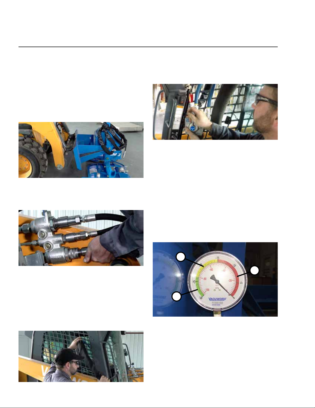
1. Connect the host machine to the mounting assembly
(Fig. 1-1). Make sure the lock levers are fully engaged.
Fig. 1-1
2. Connect the three hydraulic hoses to the host machine
using the supplied quick connects (Fig. 1-2).
5. Connect hoses to control box.
6. Mount controller to metal surface inside cab with
attached magnets (Fig. 1-4).
Fig. 1-4
7. Rotate storage legs into the operating position.
VACUUM GAUGES
Always position lifter so that the operator can see the
lifter gauge.
The lifter gauge should always read in the green range
(Fig. 1-5, 1) when operating. If the gauge is in the yellow
range (Fig. 1-5, 2), lower the load and rebuild vacuum.
We recommend you do not use the lifter below -18 inHg
(-61 kPa) of vacuum. If the gauge drops into the red range
(Fig. 1-5, 3), immediately stop, determine what the cause
is, and correct it before continuing.
Fig. 1-2
3. Position the hydraulic hoses using the attached
magnets so they do not interfere with the operation
of the host machine.
4. Route the vacuum control hoses up to the cab of host
machine. Use attached magnets to secure hoses so they
do not interfere with host machine function (Fig. 1-3).
Fig. 1-3
2
3
1
Fig. 1-5
AUXILIARY HYDRAULICS
1. Activate auxiliary hydraulics to build vacuum in
reservoir.
2. Repeat to build vacuum as necessary during operation
(refer to host machine owners manual).
Page 3
Cm series Operation
MANUAL CONTROL OPERATION
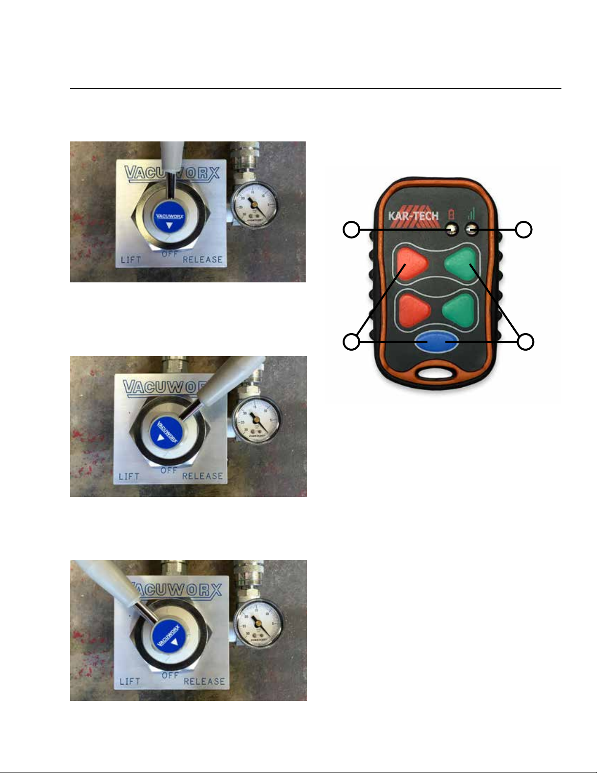
1. Start in the OFF position (Fig. 1-6).
Fig. 1-6
2. Turn the lever so the arrow points to LIFT (Fig. 1-7) to
create vacuum on the pad. Once the gauge reaches 22
it is safe to lift the load.
4. Once the gauge reaches zero the pad can be removed
from the object it was lifting.
5. Turn the switch back to the OFF position.
WIRELESS REMOTE CONTROL OPERATION
12
3 4
Fig. 1-7
3. To release the load, turn the lever so that the arrow
points to RELEASE (Fig. 1-8).
Fig. 1-9
GETTING STARTED
1. Press any button to begin operation. This will activate
the transmitter and receiver on the matched equipment
at the same time.
2. The green LED light (Fig. 1-9, 1) on the transmitter
will blink 2 times per second when the transmitter and
receiver are communicating. It will blink 1 time per
second if there is no communication (i.e. no power to
the CM 3/SL 2).
3. The red LED light (Fig. 1-9, 2) on the transmitter will
blink if the battery is low and should be replaced.
OPERATION
1. The transmitter is configured for two-handed operation.
2. To create vacuum on the pad to lift the load, lower the
pad onto the material and hold blue button and press
top red button (Fig. 1-9, 3) for 1-2 seconds. The CM 3/
SL 2 will continue to build vacuum after you release the
buttons.
Fig. 1-8
3. Once the vacuum gauge is in the green range, it is safe
to lift the load.
Page 4
Operation Cm series
4. To release vacuum, lower the load to the ground, hold
blue button and press top green button (Fig. 1-9, 4) for
1-2 seconds. The CM 3/SL 2 will continue to release the
vacuum from the pad after you release the buttons.
5. Once the gauge reaches zero the pad can be removed
from the object it was lifting.
TURNING OFF THE TRANSMITTER
Transmitter will automatically turn off after 3 seconds
of inactivity.
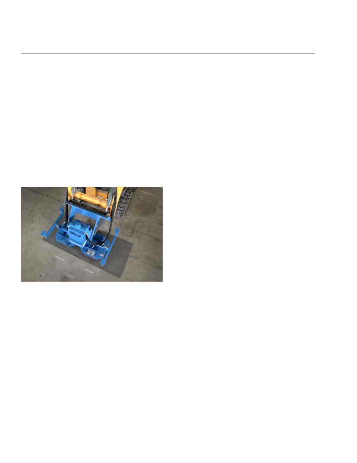
PROPERLY POSITION THE VACUUM PAD
Do not operate until the vacuum pad is properly positioned
on the material. Lift the material as close to the center as
possible to keep the load balanced.
STORING THE LIFTER
1. Reposition legs to storage position.
2. Disconnect the controller and hydraulic quick connects.
3. Wrap hoses around body of lifter.
4. Attach control unit to lifter.
5. Disconnect mounting assembly from host machine.
Fig. 1-10
LIFT, LOWER AND MOVE SLOWLY
Always lift the load slowly. Make sure the area is clear when
moving the material. All bystanders must be kept at a safe
distance. Move the host machine slowly, and carefully lower
the load into position.
Never release the vacuum while the load is being lifted.
Make sure the material is properly supported before releasing
the vacuum.
KEEP LOADS LOW
Do not lift loads higher than necessary. Always keep loads
close to the ground when possible. Never leave a suspended
load unattended. Always lower the load to the ground when
not in use.
Page 5
Cm series modular pad system
MODULAR PAD SYSTEM
CHANGING PAD BEAM
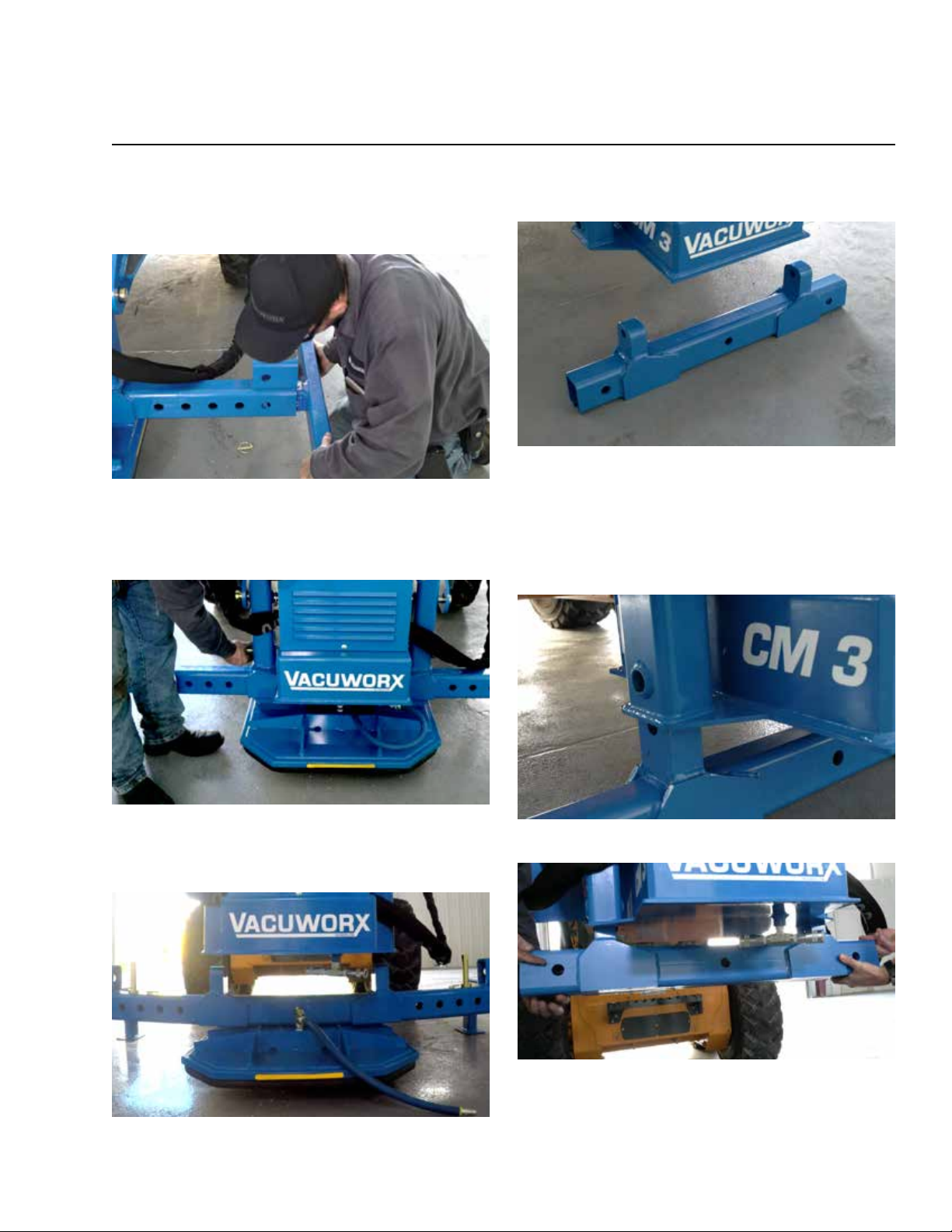
6. Position legs to the storage position and lower the
CM 3 to the ground (Fig. 3-1).
Fig. 3-1
7. Remove the pins connecting the beam to the lifter
(Fig. 3-2).
9. Slide the beam out of the way and put the other one in
its place (Fig. 3-4).
Fig. 3-4
10. Slowly lower the CM 3 onto the beam, making sure the
connection holes are lined up (Fig. 3-5). Or, with the CM
3 positioned at a comfortable working height, lift the
beam into place (Fig. 3-6).
Fig. 3-2
8. Carefully lift the CM 3 away from the beam (Fig. 3-3).
Fig. 3-3
Fig. 3-5
Fig. 3-6
Page 6
Modular PAD system cm series
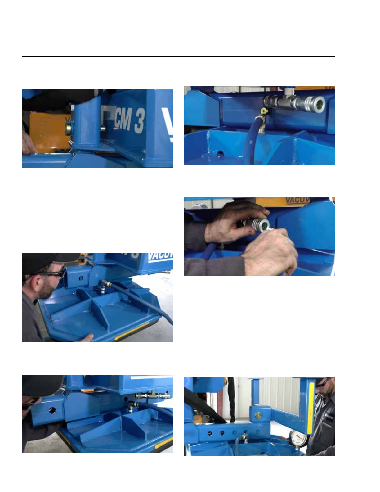
11. Reinsert the pins to connect the beam to the lifter and
install lynch pins to secure (Fig. 3-7).
Fig. 3-7
CONNECTING PAD(S)
SINGLE
12. Lift CM 3 to comfortable working height.
13. Slide on pad (gauge facing host machine & vacuum
hose on opposite end of host machine) (Fig. 3-8).
15. Insert pins to connect the pad to center of beam and
install lynch pins to secure (Fig. 3-10).
Fig. 3-10
16. Connect vacuum hose from pad to CM 3 (Fig. 3-11).
Fig. 3-8
14. Line up holes on pad to the center of the beam (Fig. 3-9).
Fig. 3-9
Fig. 3-11
DOUBLE
17. Lift CM 3 to comfortable working height.
18. Slide on pad (gauge facing host machine & vacuum
hose on opposite end of host machine) (Fig. 3-8).
19. Slide on other pad (gauge facing away from host
machine & vacuum hose on opposite end of host
machine) (Fig. 3-12).
Fig. 3-12
Page 7
cm series Modular PAD system
20. Position pads evenly apart from the center of the beam
to desired distance (lining up the holes from pads to
beam).
21. Insert pins connecting pads to beam and install lynch
pins to secure (Fig. 3-10).
22. Connect vacuum hoses from pads to CM 3 (Fig. 3-11).
DISCONNECTING PAD(S)
23. Raise CM 3 to comfortable working height.
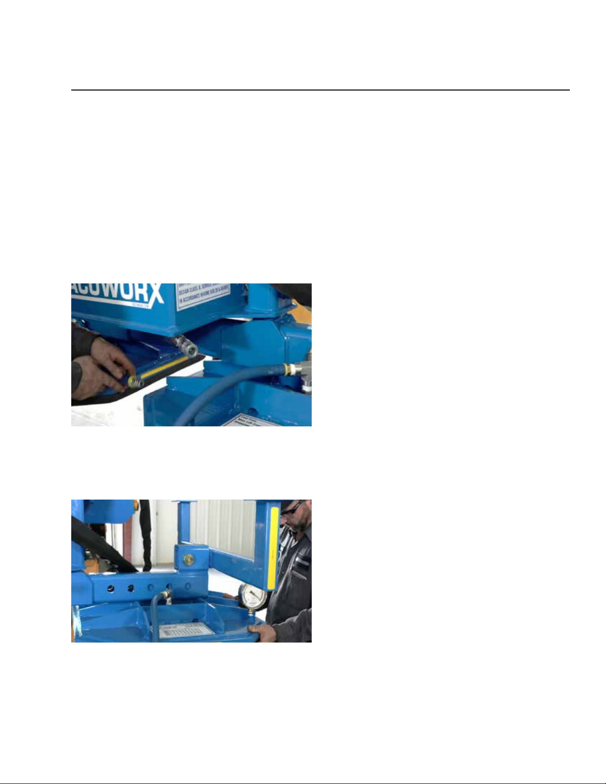
24. Disconnect pad vacuum hose(s) from CM 3 (Fig. 3-13).
Fig. 3-13
25. Remove the pad pin(s) from the beam.
26. Carefully slide the pad(s) off the beam (Fig. 3-14).
Fig. 3-14
Page 8

COPYRIGHT © 2018 VACUWORX®
PT1102-605 07/18
 Loading...