

Vacuubrand pc 3001 VARIO select, pc 3001 VARIO select TE, pc 3001 VARIO select IK, pc 3001 VARIO select EKP User guide
Page 1
Technology for Vacuum Systems
Chemistry pumping unit series
PC 3001 VARIO select
PC 3001 VARIO select TE
PC 3001 VARIO select IK
PC 3001 VARIO select EKP
Instructions for use
Original instructions EN
OI no.: 20901367
Page 2

Imprint
Original instructions
Keep for further use!
This manual is only to be used and distributed in its complete and original form. It is strictly the user's responsibility to
carefully check the validity of this manual with respect to the product.
Manufacturer:
VACUUBRAND GMBH + CO KG
Alfred‑Zippe‑Str. 4
97877 Wertheim
GERMANY
Phone:
Head ofce +49 9342 808‑0
Sales +49 9342 808‑5550
Service +49 9342 808‑5660
Thank you for purchasing this product from VACUUBRAND GMBH + CO KG . You have chosen a modern and
technically high quality product.
2 20901367_EN_PC3001_VARIO_select_Serie_V1.2_100220
Page 3

Content
TABLE OF CONTENT
1 Introduction 5
1.1 User information.................................5
1.2 About this document..............................6
1.2.1 Manual structure .............................6
1.2.2 Display conventions ..........................7
1.2.3 Symbols and icons ...........................8
1.2.4 Handling instructions (action steps)...............9
1.2.5 Abbreviations ...............................9
1.2.6 Term denitions.............................10
2 Safety information 12
2.1 Usage........................................12
2.1.1 In tende d u se ...............................12
2.1.2 Improper use...............................13
2.1.3 Foreseeable misuse............................ 13
2.2 Obligations ....................................14
2.2.1 Operator obligations .........................14
2.2.2 Personnel obligations ........................14
2.3 Target group description..........................15
2.4 Safety precautions, general .......................16
2.4.1 Protective clothing...........................16
2.4.2 Safety precautions ..........................16
2.4.3 Laboratory and working materials...............17
2.4.4 Eliminate sources of danger ...................18
2.5 Motor protection ................................21
2.6 ATEX equipment category ........................22
2.7 Proper disposal ................................23
3 Product description 24
3.1 PC 3001 VARIO select (basic design)................24
3.2 Chemistry pumping units .........................25
3.3 Condensers and coolers .........................26
3.3.1 Separator / Condenser at the inlet ..............26
3.3.2 Condenser at the outlet.......................27
3.4 Examples of use................................29
4 Installation and connection 30
4.1 Transport .....................................30
4.2 Installation ....................................31
320901367_EN_PC3001_VARIO_select_Serie_V1.2_100220
Page 4

Content
4.3 Connection ....................................32
4.3.1 Vacuum connection (IN) ......................32
4.3.2 Exhaust gas connection (EX) ..................34
4.3.3 Coolant connection at the condenser ............35
4.3.4 Dry ice condenser...........................36
4.3.5 Venting connection ..........................39
4.3.6 Gas ballast (GB) ............................41
4.3.7 Electrical connection.........................42
5 Initial use (operation) 44
5.1 Switch on .....................................44
5.2 Operation ....................................44
5.2.1 Operation ( see description of controller)........46
5.2.2 Operation with gas ballast.....................47
5.3 Decommissioning (switch off)......................48
5.4 Storage.......................................49
6 Troubleshooting 50
6.1 Technical support ...............................50
6.2 Error – Cause – Remedy .........................50
7 Cleaning and maintenance 54
7.1 Information on service work .......................55
7.2 Cleaning ......................................57
7.2.1 Housing surface ............................57
7.2.2 Empty glass ask ...........................57
7.2.3 Clean sensor and venting valve ................58
7.2.4 Clean or replace molded PTFE‑hose ............61
7.3 Vacuum pump maintenance.......................62
7.3.1 Maintenance items ..........................62
7.3.2 Change diaphragms and valves ................64
8 Appendix 74
8.1 Technical information ............................74
8.1.1 Technical data.............................. 74
8.1.2 Wetted materials............................76
8.1.3 Rating plate................................77
8.2 Ordering information.............................78
8.3 Service .......................................80
8.4 Index.........................................81
8.5 EC Declaration of Conformity......................83
4 20901367_EN_PC3001_VARIO_select_Serie_V1.2_100220
Page 5

Introduction
1 1 IntroductionIntroduction
This manual is part of your product. The manual applies to all
variants of the pumping unit, together with the VACUU·SELECT®
manual, and is intended in particular for laboratory staff.
1.1 1.1 User informationUser information
Safety
Instructions for use
and safety
General
information
Read this manual thoroughly and completely before using the
produkt.
Keep this manual in an easily accessible location.
Correct use of the product is essential for safe operation. Comply
with all safety information provided!
In addition to this manual, adhere to the accident prevention
regulations and industrial safety regulations applicable in the
country of use.
General
For easier readability, the general term pumping unitpumping unit is
used as an equivalent to and instead of the product name
Chemistry pumping unit PC 3001 VARIO selectChemistry pumping unit PC 3001 VARIO select.
If passing the product on to a third party, also give them this
manual.
The illustrations in this manual are only intended to facilitate
comprehension.
Copyright ©
We reserve the right to make technical and design changes in
the course of continuous product improvement.
Copyright
The content of this manual is protected by copyright. Only copies
for internal use are allowed, e. g., for professional training.
© VACUUBRAND GMBH + CO KG
520901367_EN_PC3001_VARIO_select_Serie_V1.2_100220
Page 6
Introduction
Contact
Contact us
Modular instructions
for use
If your manual is incomplete, you can request a replace‑
ment. Alternatively, you can use our download portal:
www.vacuubrand.com
You are welcome to contact us at any time in writing or by tele‑
phone if you would like more information, have questions about
our products or wish to share feedback with us.
When contacting our Service Department, please have the
serial number and product type at hand see Rating plateRating plate on
the product.
1.2 1.2 About this documentAbout this document
1.2.1 1.2.1 Manual structureManual structure
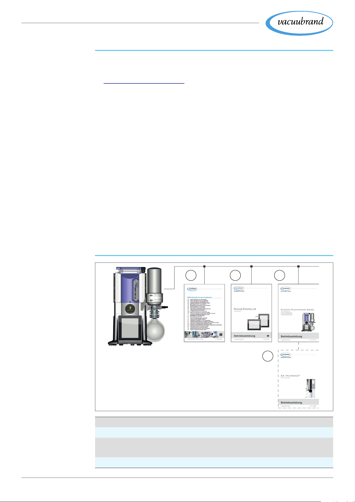
The manuals have a modular structure with separate instruction
modules for the controller, vacuum pumps, pumping units, and
any accessories.
Pumping unit series
and instructions for
use
Instruction modules
1
1
Safety Information for Vacuum Equipment
2
Description: Vacuum controller – control and operation
3
Description: Pumping unit – connection, operation, maintenance,
mechanics
4
Optional description: Accessories
2
3
4
6 20901367_EN_PC3001_VARIO_select_Serie_V1.2_100220
Page 7
1.2.2 1.2.2 Display conventionsDisplay conventions
Warning levels
Introduction
Display conventions
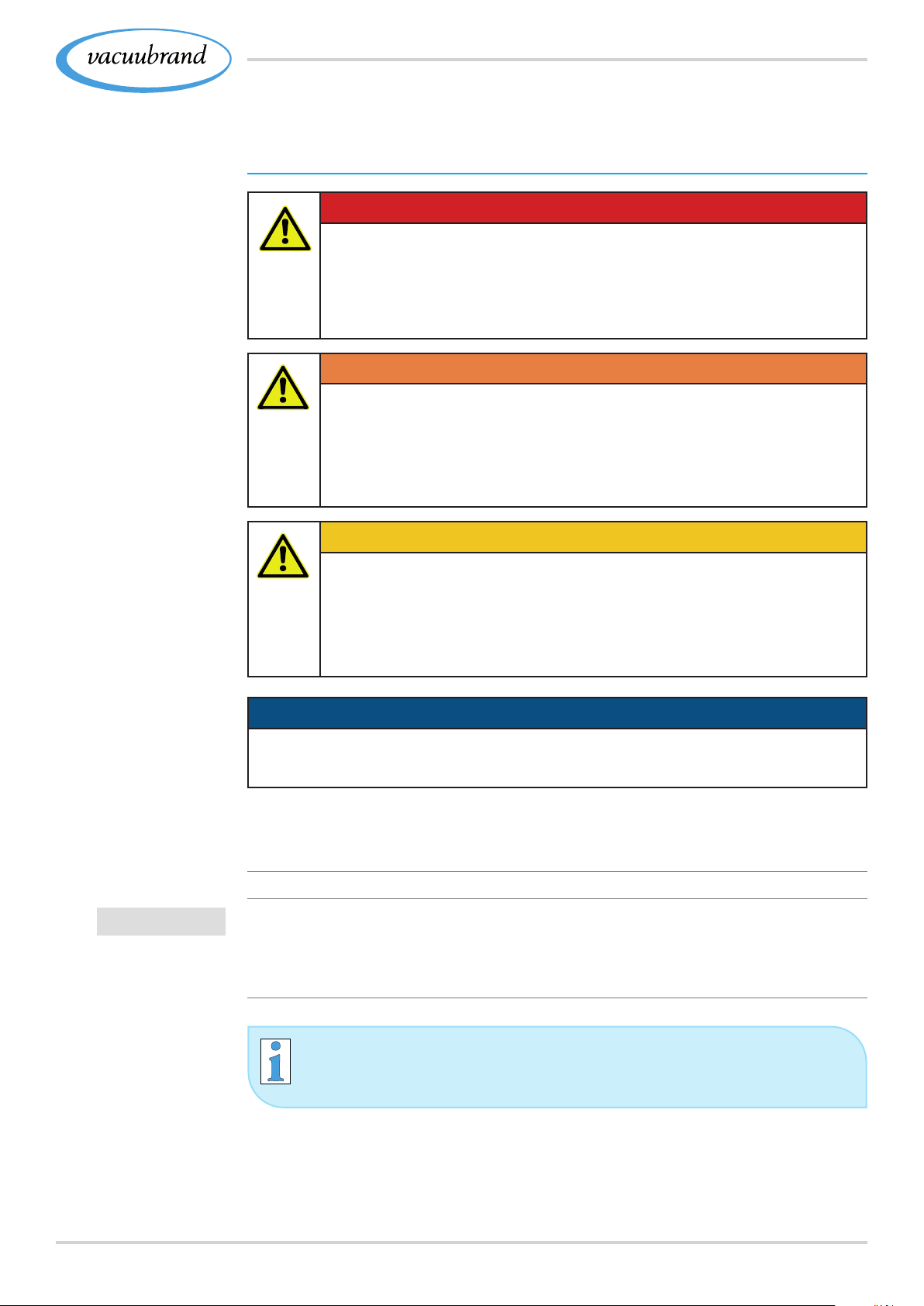
DANGERDANGER
Indicates an imminent hazardous situation.
Disregarding the situation will result in serious and
even fatal injury or death.
> Take appropriate action to avoid dangerous situation!
WARNING
Indicates a potentially hazardous situation.
Disregarding the situation could result in serious, even
fatal injury or massive damage to property.
> Take appropriate action to avoid dangerous situation!
CAUTION
Indicates a potentially hazardous situation.
Disregarding the situation could result in slight or minor
injury or damage to property.
IMPORTANT!
> Take appropriate action to avoid dangerous situation!
NOTICENOTICE
Notice for a potentially harmful situation.
Disregarding the notice could lead to material damage.
Additional notes
> Information or specic use recommendation, which must be
observed.
> Important information for proper operation.
> Helpful tips + tricks
> Additional notes
720901367_EN_PC3001_VARIO_select_Serie_V1.2_100220
Page 8
Introduction
1.2.3 1.2.3 Symbols and Symbols and iconsicons
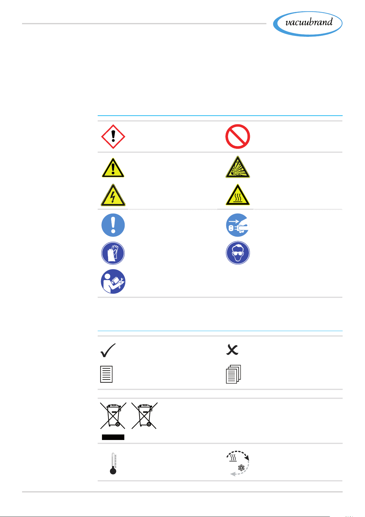
This manual uses symbols and icons. Safety symbols indicate
specic risks associated with handling the product. Symbols and
icons are designed to help you identify risks more easily.
Safety symbols
Explanation of
safety symbols
Hazardous substance ‑
hazards to human health.
General
warning sign.
Danger: electricity Danger: hot surface
General
mandatory sign.
Wear chemical resistant
protective gloves.
Read instructions for
repair.
General
prohibition sign.
Warning
Risk of explosion.
Disconnect mains plug.
Wear protective goggles.
Additional icons
Additional
symbols
8 20901367_EN_PC3001_VARIO_select_Serie_V1.2_100220
Positive example – Do this!
Result – OK
Refers to content in
this manual.
Electric/electronic devices must not be disposed of in
the domestic waste at the end of their service life.
Installation at
temperatures < 40 °C
(< 104 °F).
Negative example –
Do not do this!
Refers to content of
other supplementary docu‑
ments.
Ensure sufcient air circu‑
lation.
Page 9

Introduction
Display of action
steps
Flow arrow
Inlet – vacuum connection
Flow arrow
Outlet – exhaust gas
1.2.4 1.2.4 Handling instructions (action steps)Handling instructions (action steps)
Instructions (single step)
> Perform the step described.
5 Result of action
Instructions (multiple steps)
1. First step
2. Next step
5 Result of action
Abbreviations
Perform the steps in the order described.
1.2.5 1.2.5 AbbreviationsAbbreviations
abs. Absolute
AK Separator ask
ATM Atmospheric pressure (pressure graphic, program)
(di)
d
i
DN Nominal diameter
EK Vapor condenser
EKP Emission condenser Peltronic
EX* Outlet (exhaust, exit), exhaust gas connection
`
FKM Fluoroelastomer
GB Gas ballast
Gr. Size
Interior diameter
ATEX equipment labeling
®
or EK Peltronic
®
IK Inlet condenser
IN* Inlet, vacuum connection
KF Small ange
max. Maximum value
min. Minimum value
o. EK without vapor condenser
920901367_EN_PC3001_VARIO_select_Serie_V1.2_100220
Page 10

Introduction
Abbreviations
Product‑specic
terms
PA Polyamide
PBT Polybutylene terephthalate
PC .... Chemistry pumping unit with type identication number
PE Polyethylene
RMA‑N° Return Merchandise Authorization number
SW Wrench size (tool)
TE Dry ice condenser
resp. responsible (supervising)
e. g., for example
* Labeling on vacuum pump or component
see also
Product-specic abbreviations on page 25Product-specic abbreviations on page 25
1.2.6 1.2.6 Term denitionsTerm denitions
Separator ask Glass ask / separator mounted at the inlet or
outlet.
Vapor condenser* Cooling condenser with receiving ask mount‑
ed at the outlet (pressure side).
Immission con‑
denser*
PC 3001 VARIO
select
Peltronic
®
Cooling condenser with receiving ask mount‑
ed at the inlet (vacuum side).
Vacuum pumping unit with speed control for
precise vacuum regulation with controller
VACUU·SELECT
®
.
Electronic cooler with Peltier elements mounted
at the outlet; condenses solvent vapors without
external coolant.
Dry ice
condenser*
Cooling condenser with receiving ask mount‑
ed at the outlet (pressure side) and dry ice as
coolant.
VACUU·BUS
®
Bus system from VACUUBRAND for com‑
munication between peripheral devices with
VACUU·BUS® enabled gauges and control‑
lers. The maximum permissible cable length is
30 m.
VACUU·BUS
address
®
Address which enables the VACUU·BUS® client
to be unambiguously assigned within the bus
system, e. g., for connecting multiple sensors
with the same measurement range.
VACUU·BUS
client
®
Peripheral device or component with
VACUU·BUS® port which is integrated in the
bus system, e. g., sensors, valves, level indica‑
tors, etc.
10 20901367_EN_PC3001_VARIO_select_Serie_V1.2_100220
Page 11

Introduction
Product‑specic
terms
VACUU·BUS®
connector
VACUU·BUS
®
conguration
4‑pin round connector for the bus system from
VACUUBRAND.
Assigning a different VACUU·BUS® address to
a VACUU·BUS® component using a gauge or
controller.
VACUU·SELECT
®
Vacuum controller, controller with touchscreen;
consisting of operating panel and vacuum sen‑
sor.
VACUU·SELECT
®
Vacuum sensor with integrated venting valve.
Sensor
VARIO
®
drive Speed control for vacuum pump; the motor
runs only as fast as necessary to meet de‑
mand.
* only suitable for condensation of vapors
1120901367_EN_PC3001_VARIO_select_Serie_V1.2_100220
Page 12

Safety information
2 2 Safety informationSafety information
The information in this chapter must be observed by everyone
who works with the product described here.
The safety information is valid for the entire life cycle of the prod‑
uct.
2.1 2.1 UsageUsage
Only use the product if it is in perfect working condition.
2.1.1 2.1.1 Intended useIntended use
Intended use
A chemistry pumping unit of the PC 3001 VARIO selectPC 3001 VARIO select product
series is a vacuum system consisting of a vacuum pump, control‑
ler, sensor and separator, for the creation and control of rough
vacuum in designated systems, e. g. evacuating distillation instru‑
ments, in particular rotary evaporators.
Attached coolers (vapor condenser, immission condenser, dry ice
®
cooler, emission condenser Peltronic
), including separators and
asks, are exclusively intended for the condensation of vapors.
The device may only be used indoors in a non‑explosive atmo‑
sphere, and in a dry environment.
Intended use also includes:
observing the information in the document
Safety information for vacuum equipment,
observing the manual,
observing the manual of connected components,
observing the inspection and maintenance intervals and having
it performed by appropriately qualied personnel.
using only approved accessories or spare parts.
Any other use is considered as improper use.
12 20901367_EN_PC3001_VARIO_select_Serie_V1.2_100220
Page 13

2.1.2 2.1.2 Improper useImproper use
Safety information
Improper use
Incorrect use or any application which does not correspond to the
technical data may result in injury or damage to property.
Improper use includes:
using the product contrary to its intended use,
operation at improper environmental and operating conditions,
operation despite obvious malfunctions or defective safety devices,
unauthorized modications or conversions, in particular when
these impair safety,
usage despite incomplete assembly,
operation with sharp‑edged objects,
pulling plug‑in connections on the cable out of the socket,
to pump, to convey and to compress solids or uids.
Foreseeable misuse
2.1.3 2.1.3 Foreseeable misuseForeseeable misuse
In addition to improper use, there are types of use which are pro‑
hibited when handling the device:
Prohibited types of use are, in particular:
use on humans or animals,
installation and operation in potentially explosive atmospheres,
use in mines or underground,
using the device to generate pressure,
fully exposing vacuum devices to the vacuum,
immersing it in liquids, exposing it to water spray or steam jets,
pumping oxidizing and pyrophoric substances, liquids or solids,
pumping of hot, unstable, or explosive media,
pumping substances which may react explosively under impact
and/or elevated temperature without an air supply.
IMPORTANT!
The penetration of foreign objects, hot gases and ames
from the application, must be excluded.
1320901367_EN_PC3001_VARIO_select_Serie_V1.2_100220
Page 14

Safety information
2.2 2.2 ObligationsObligations
2.2.1 2.2.1 Operator obligationsOperator obligations
Operator obligations
Personnel
obligations
The owner denes the responsibilities and ensures that only
trained personnel or specialists work at the vacuum system. This
applies in particular to connection, assembly and maintenance
work and troubleshooting.
Users in the areas of competence in the
Responsibility matrixResponsibility matrix
must possess the relevant qualications for the activities listed.
Work on electrical equipment in particular may be performed only
by electricians.
2.2.2 2.2.2 Personnel obligationsPersonnel obligations
In the case of activities which require protective clothing, personal
protective equipment as specied by the operator is to be worn.
If the vacuum system is not in proper order, it must be secured
against being accidentally switched back on.
> Always be conscious of safety and work in a safe manner.
> Observe instructions issued by the operator, and national reg‑
ulations on accident prevention and industrial safety.
Personal behaviour may help to avoid work accidents.
14 20901367_EN_PC3001_VARIO_select_Serie_V1.2_100220
Page 15
2.3 2.3 Target group descriptionTarget group description
Safety information
Target groups
Qualication
description
Responsibility
Assignment Matrix
The manual must be read and observed by every person who is
tasked with the activities described below.
Personnel qualication
Operators Laboratory staff, such as chemists, laboratory techni‑
cians
Specialist Person with professional qualication in mechanics,
electrical equipment or laboratory devices
Responsible
specialist
Similar to a specialist, with additional specialist re‑
sponsibility, or responsibility for a department or divi‑
sion
Responsibility matrix
Activity Operators Specialist
Installation x x x
Responsible
specialist
Commissioning x x x
Network integration x
Operation x x x
Error report x x x
Remedy x x x
Maintenance x x
Repair
1
x x
Repair order x
Cleaning, simple x x x
Empty separator ask x x x
Shutdown x x x
Decontamination
1 see also website:
VACUUBRAND > Support > Instructions for repair
2 Alternatively, arrange for decontamination by a qualied service provider
2
x x
1520901367_EN_PC3001_VARIO_select_Serie_V1.2_100220
Page 16
Safety information
2.4 2.4 Safety precautions, generalSafety precautions, general
Quality standards
and safety
Protective clothing
IMPORTANT!
Products from VACUUBRAND GMBH + CO KG are subject
to stringent quality testing with regard to safety and operation.
Each product undergoes a comprehensive test program prior to
delivery.
2.4.1 2.4.1 Protective clothingProtective clothing
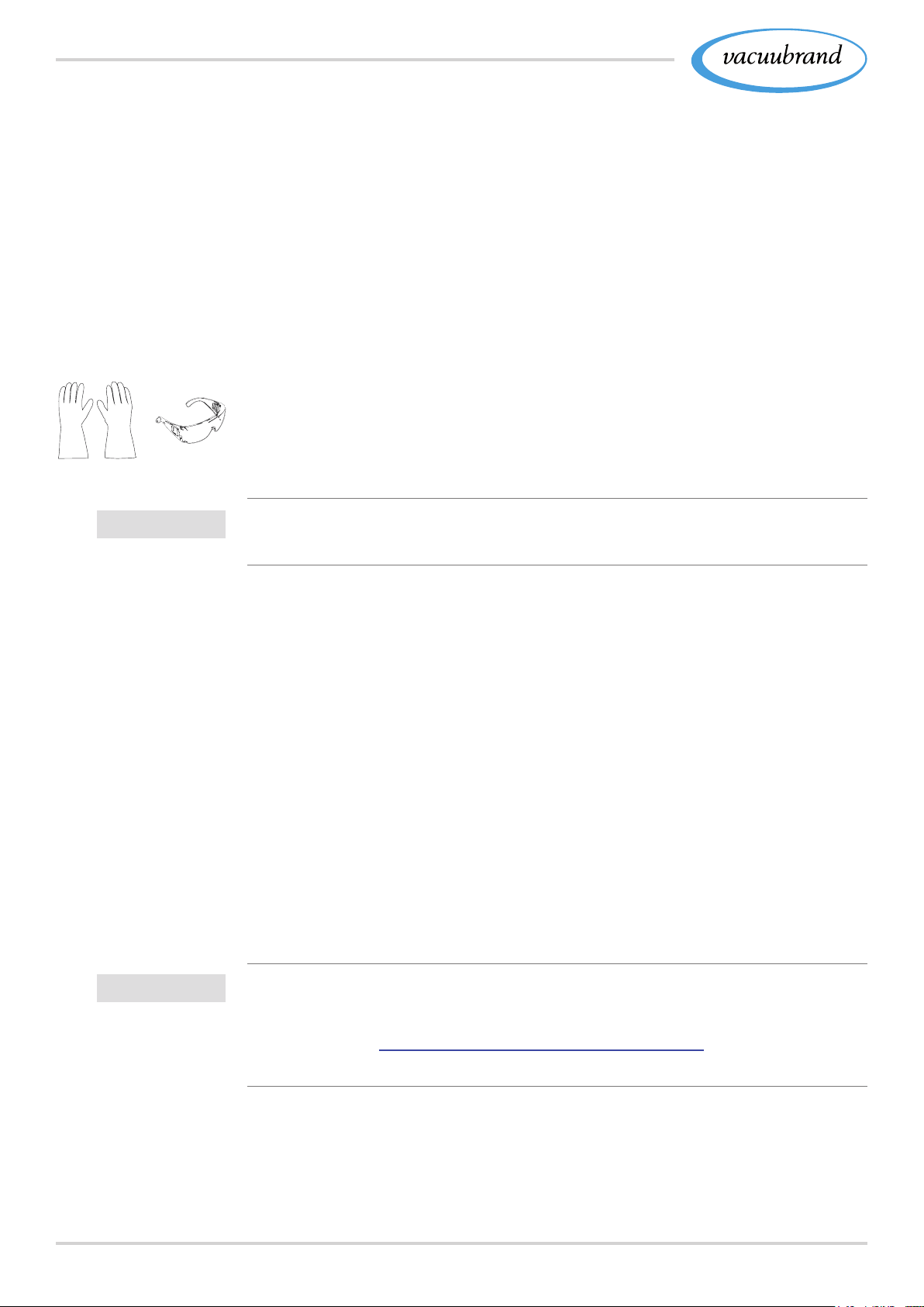
For operation no special protective clothing is required. Observe
the owners' directives at work for your workplace.
During cleaning, maintenance and repair work, we recommend
wearing full protective gloves, protective clothing and protective
goggles.
> When handling chemicals, wear your personal protective
equipment.
Safety precautions
IMPORTANT!
2.4.2 2.4.2 Safety precautionsSafety precautions
> Use the vacuum device only if you have understood its func‑
tion and this manual.
> Replace defective parts immediately, e. g., a broken cable,
faulty ask or faulty hose.
> Use only original accessories and components which are
designed for the vacuum technology, such as a vacuum hose,
separator, vacuum valve, etc.
> When handling contaminated parts, follow the relevant regu‑
lations and safety precautions, this also applies to equipment
sent in for repair.
Prior to any service, contamination from hazardous sub‑
stances needs to be excluded.
> Fill out the Health and Safety Clearance form in full and con‑
rm with your signature.
16 20901367_EN_PC3001_VARIO_select_Serie_V1.2_100220
Page 17
Safety information
2.4.3 2.4.3 Laboratory and working materialsLaboratory and working materials
DANGERDANGER
Hazardous substances could emit at the outlet.
During aspiration, hazardous, toxic substances at the
outlet can get into ambient air.
> Observe the national regulations for safe handling of
hazardous substances.
> Please note that residual process media may pose a
danger to people and the environment.
> Mount and use suitable separators, lters or fume
hood devices.
Risks due to various substances
Pumping different
substances
Pumping different substances or media can cause the substances
to react with one another.
Working substances which get into the vacuum pump with the gas
ow can damage the vacuum pump. Hazardous substances can
deposit in the vacuum pump.
Possible safety precautions, depending on the application:
> Flush the vacuum pump with inert gas or air before changing
the medium to be pumped.
> Use inert gas to dilute critical mixtures.
> Prevent the release of hazardous, toxic, explosive, corrosive
uids, gases or vapors or those that are harmful to health or
the environment, for example, through suitable laboratory facil‑
ities with a fume hood and ventilation control.
> Protect the inside of the vacuum pump from deposits or mois‑
ture, e. g, through the provision of a gas ballast.
> Be aware of interactions and possible chemical reactions of
the pumped media.
> Check the compatibility of the pumped substances with the
wetted materials of the pumping unit.
> Contact us if you have concerns about using your vacuum
pump with certain working materials or media.
1720901367_EN_PC3001_VARIO_select_Serie_V1.2_100220
Page 18

Safety information
2.4.4 2.4.4 Eliminate sources of dangerEliminate sources of danger
Take mechanical stability into account
Note mechanical
load capacity
Due to the high compression ratio of the pump, pressure can de‑
velop at the outlet which exceeds that which the mechanical sta‑
bility of the system allows.
> Always ensure that the exhaust gas line is clear and non‑pres‑
surized. To ensure unhindered emission of gases, the outlet
should not be blocked.
> Prevent uncontrolled overpressure, for example, due to a
locked or blocked piping system, condensate or clogged
exhaust gas line.
> At the gas connections, the connections for the inlet
outlet
EXEX should not be mixed up.
ININ and
> Be aware of the max. pressures at the inlet and outlet of the pump
as well as the max. admissible differential pressure between the
inlet and outlet, according to
8.1.1 Technical data on page 748.1.1 Technical data on page 74
> The system to be evacuated as well as all hose connections
must be mechanically stable.
Prevent backup in
the exhaust gas line
> Fix coolant hoses to the hose nozzles such that they cannot
inadvertently become loose.
Prevent condensate reow
Condensate can damage the pump head. No condensate should
ow back into the outlet
EXEX and pump head due to the hose line.
No liquid should accumulate inside the exhaust hose.
> Avoid condensate return by using a separator. No condensate
must enter the housing interior via the vacuum hoses.
> Preferably lay the exhaust gas hose such that it descends
from the outlet; that is, position it running downward so that no
backup forms.
18 20901367_EN_PC3001_VARIO_select_Serie_V1.2_100220
Page 19

Safety information
Avoid incorrect
measurements
Observe vacuum
pump dimensioning
Incorrect measurement due to an obstructed vacuum line, e. g.,
condensate in the vacuum line can distort the measurements of
the vacuum sensor.
> Prevent overpressure > 1060 mbar (795 Torr) inside the suc‑
tion line.
Avoid foreign bodies inside the pump
Part ic les, liqui ds and du sts shou ld not get insi de the va cuum pump.
> Do not pump any substances which could form deposits
inside the vacuum pump.
> Install suitable separators and/or lters in front of the inlet.
Suitable lters are, e. g, chemically resistant, clog‑proof and
have a reliable ow rate.
> Immediately replace porous vacuum hoses.
Be aware of risks
during venting
Possible
residual energies
Risks during venting
Depending on the application, venting can cause explosive mix‑
tures to form or other hazardous situations to arise.
Risks due to residual energy
After the device has been switched off and disconnected from the
power supply, there may still be dangers at the plug‑in power sup‑
ply due to residual energy:
■ Thermal energy: Motor waste heat, hot surface, compression
heat.
> Allow the vacuum pump to cool off.
■ Electrical energy: In capacitors on the electronics, they have a
discharge time of up to 3 minutes.
> Wait for at least 3 minutes until capacitors have discharged.
1920901367_EN_PC3001_VARIO_select_Serie_V1.2_100220
Page 20

Safety information
Risk of burns due to hot surface
Surface tempera‑
tures
Overheating
The surface of the vacuum pump can reach operating tempera‑
tures higher than > 70 °C, in particualar when pumping heated
media.
> Avoid direct contact with the surface.
> Use protection against accidental contact if the surface tem‑
perature is regularly elevated.
> Allow the vacuum pump to cool off before performing mainte‑
nance work.
The vacuum pump can be damaged due to overheating. Possi‑
ble causes include insufcient air supply to the fan and failure to
maintain minimum distances.
> When installing the device, ensure that there is a minimum
distance of 5 cm between the cooling fan and adjacent parts
(such as the housing, walls, etc.).
> Always ensure sufcient air supply; if applicable, provide
external forced ventilation.
> Place the device on a stable surface; a soft surface such as
foam rubber as a sound absorber can impair and block the air
supply.
> Clean polluted ventilation slots.
> Remove covers from the device before operating it.
> Avoid excessive heat input due to hot process gases.
> Observe the maximum admissible media temperature
see chapter:
8.1.1 Technical data on page 748.1.1 Technical data on page 74.
20 20901367_EN_PC3001_VARIO_select_Serie_V1.2_100220
Page 21

Safety information
Handling coolants and cryogenic materials
Risks when handling
with cryogenic sub‑
stances
Cryogenic materials can cause frostbite (cold burns) upon contact
with skin.
> Observe the valid regulations for handling cryogenic sub‑
stances.
> Use only approved transport containers.
> Take the necessary safety precautions when handling cryo‑
genic media, such as dry ice.
> Never use damaged components.
> Wear your personal protective equipment when handling haz‑
ardous materials.
> Ensure ventilation of the workplace.
Dry ice should not be used in gas‑tight containers. Do not x the
cover on top of the dry ice condenser. Pressure equalization be‑
tween the coolant and the atmosphere must be ensured at all
times.
Warning signs and
labels
Overheating
protection, blockage
protection
Procedure for
switching vacuum
pump back on
Keep signs legible
Keep labels and information symbols and warning labels always
in a well readable condition:
> Connection labeling
> Warning signs and notice labels
> Motor data and rating plates
2.5 2.5 Motor protectionMotor protection
The pump motor has a temperature sensor on the circuit board as
overload protection. In the event of excessive temperature or if the
motor is blocked, the vacuum pump switches off.
If the vacuum pump is switched off due to these safety precau‑
tions, the fault must be manually reset: Unplug pumping unit from
power supply ‑> eliminate cause of error ‑> switch pumping unit
back on.
2120901367_EN_PC3001_VARIO_select_Serie_V1.2_100220
Page 22
Safety information
2.6 2.6 ATEX equipment categoryATEX equipment category
Installation and potentially explosive atmospheres
The installation and operation in areas where potentially ex‑
plosive atmospheres can develop to a hazardous degree is
not permitted.
ATEX approval only applies to the internal, wetted parts of
the of the product, not to its surroundings.
ATEX equipment labeling
ATEX
equipment category
ATEX
equipment category
and peripherals
Prevent
ignition source
Vacuum equipment labeled with
has ATEX approval in line
`
with the ATEX marking on the rating plate.
> Only use the product if it is in perfect working condition.
> The devices are designed for a low level of mechanical
stress and must be installed in such a way that they cannot
sustain mechanical damage from the outside.
The ATEX category of the product is dependent on the connected
peripheral devices. Components and connected peripherals need
to have the same or higher ATEX approval.
The use of gas ballast and/or venting valves is only permitted if
this would not normally, or only rarely, cause explosive mixtures
within the device, or do so only for a short time.
> If necessary vent with inert gas.
Information on the ATEX equipment category is also available on
our website at: www.vacuubrand.com/.../Information‑ATEX
22 20901367_EN_PC3001_VARIO_select_Serie_V1.2_100220
Page 23
Safety information
2.7 2.7 Proper disposalProper disposal
NOTENOTE
Electronic components and batteries must not be
disposed of in the domestic waste at the end of their
service life.
Used electronic devices and batteries contain harmful sub‑
stances that can cause damage to the environment or human
health. Disused electrical devices also contain valuable raw
materials, which can be recovered for reuse if the device is dis‑
posed of correctly within the recycling process.
End users are legally obliged to take used electric and elec‑
tronic devices to a licensed collection point and to return spent
batteries.
> It is your responsibility to save and delete any data before
disposing of your electronic device.
> If the device contains batteries: Remove spent batteries
before disposal.
> Correctly dispose of all electronic scrap and electric compo‑
nents at the end of their service life.
> Observe the national regulations regarding disposal and
environmental protection.
2320901367_EN_PC3001_VARIO_select_Serie_V1.2_100220
Page 24
Product description
3 3 Product descriptionProduct description
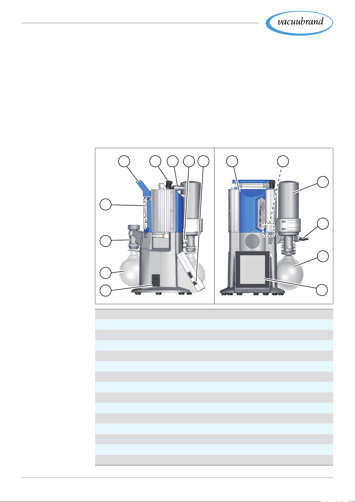
Pumping units of the PC 3001 VARIO select series generally
consist in each case of a diaphragm pump with VARIO® drive,
a VACUU·SELECT
separator. Condensors are available in various designs. The
differences concern the functioning of the cooler.
3.1 3.1 PC 3001 VARIO select (basic design)PC 3001 VARIO select (basic design)
Side and front view,
basic model
®
vacuum controller as well as a cooler with
65
7 9
8
10
11
12
Meaning
4
3
2
1
1
Power connection with on/off switch (rocker switch)
2
Separator ask, round bottom ask at the inlet
3
Distribution head
4
Rating plate
5
Handle
6
Gas ballast valve
7
Connections at the EK: Outlet, coolant
8
Overpressure relief valve
9
ON/OFF button vacuum controller
10
Chemistry diaphragm pump
11
VACUU·SELECT® Sensor, mounted inside the pumping unit
12
Vapor condenser EK
13
Vacuum inlet, on the rear round bottom ask
14
Round bottom ask at the outlet
15
VACUU·SELECT® operating panel, removable
13
14
15
24 20901367_EN_PC3001_VARIO_select_Serie_V1.2_100220
Page 25
Product description
3.2 3.2 Chemistry pumping unitsChemistry pumping units
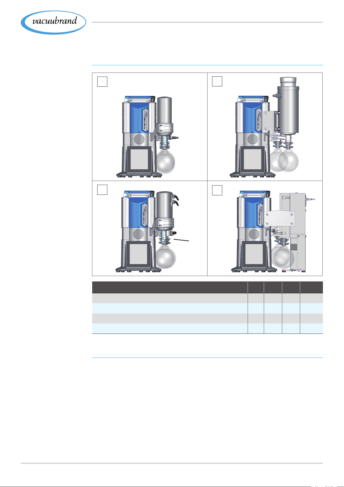
Overview of the PC 3001 VARIO select Series
Overview
Chemistry pumping
units
a
b
TETE
EKEK
c
EKEK
d
EKPEKP
IKIK
rear
Meaning
Product‑specic
abbreviations
Chemistry pumping unit AK IK EK EKP
a PC 3001 VARIO select
b PC 3001 VARIO select TE
c PC 3001 VARIO select IK
d PC 3001 VARIO select EKP
● ●
● ●
● ●
● ●
Product-specic abbreviations
AK Separator ask
EK Vapor condenser, mounted at the outlet
®
EKP Peltronic
IK Immission condenser, mounted at the inlet
o. EK without vapor condenser
PC .... Chemistry pumping unit with type identication number
TE Dry ice condenser, dry ice cooler
emission condenser, mounted at the outlet
2520901367_EN_PC3001_VARIO_select_Serie_V1.2_100220
Page 26
Product description
3.3 3.3 Condensers and coolersCondensers and coolers
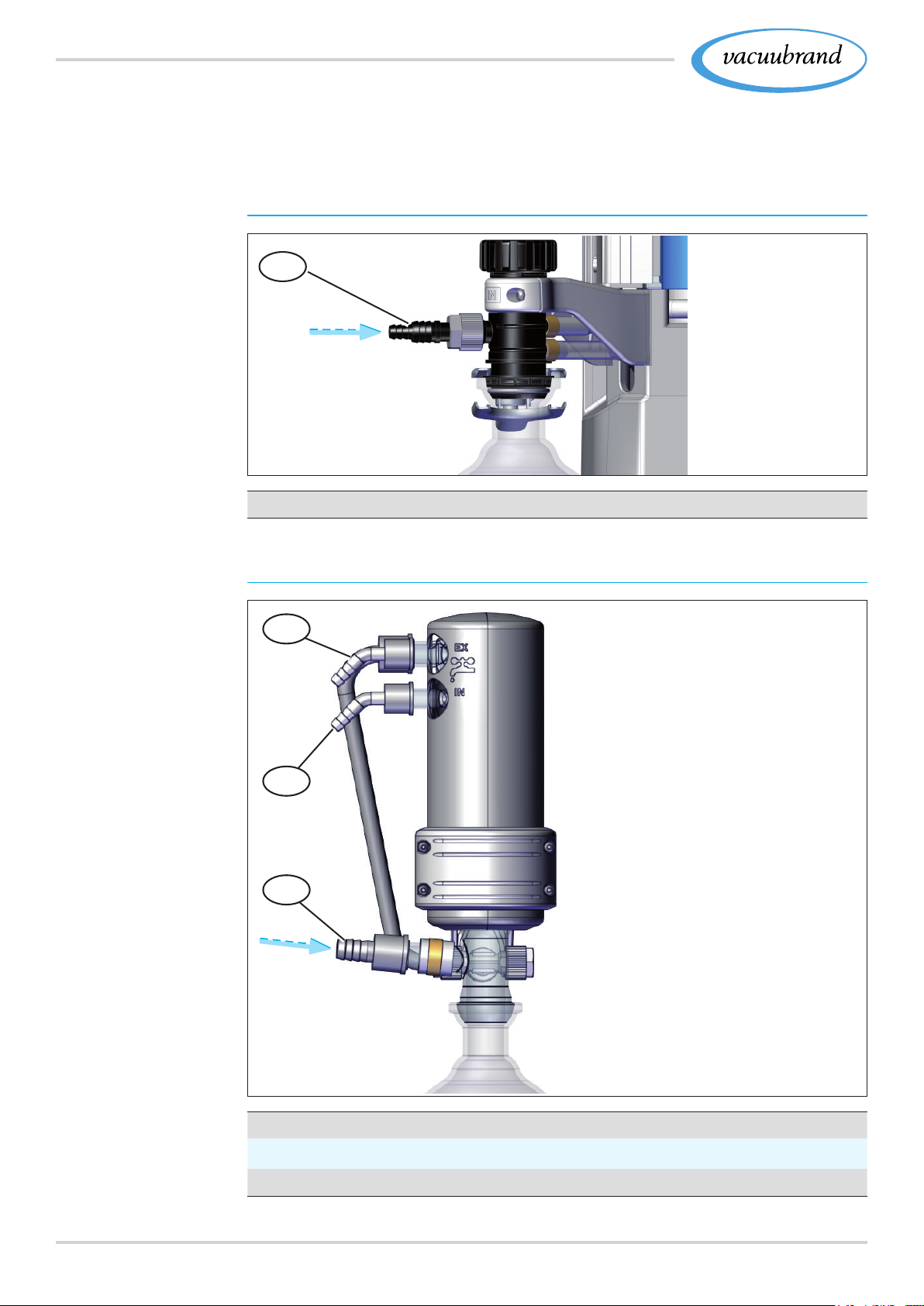
3.3.1 3.3.1 Separator / Condenser at the inletSeparator / Condenser at the inlet
Connection to separator ask
Connections at the
AK
13
Meaning
Connections at the
IK
13
Inlet connection vacuum IN
Connection and coolant at the immission condenser
13.3
13.2
13.1
PC 3001 VARIO select IK
Meaning
26 20901367_EN_PC3001_VARIO_select_Serie_V1.2_100220
13.1
13.2
13.3
Inlet connection vacuum IN
Inlet connection coolant IN, e. g, water
Outlet connection coolant EX
Page 27
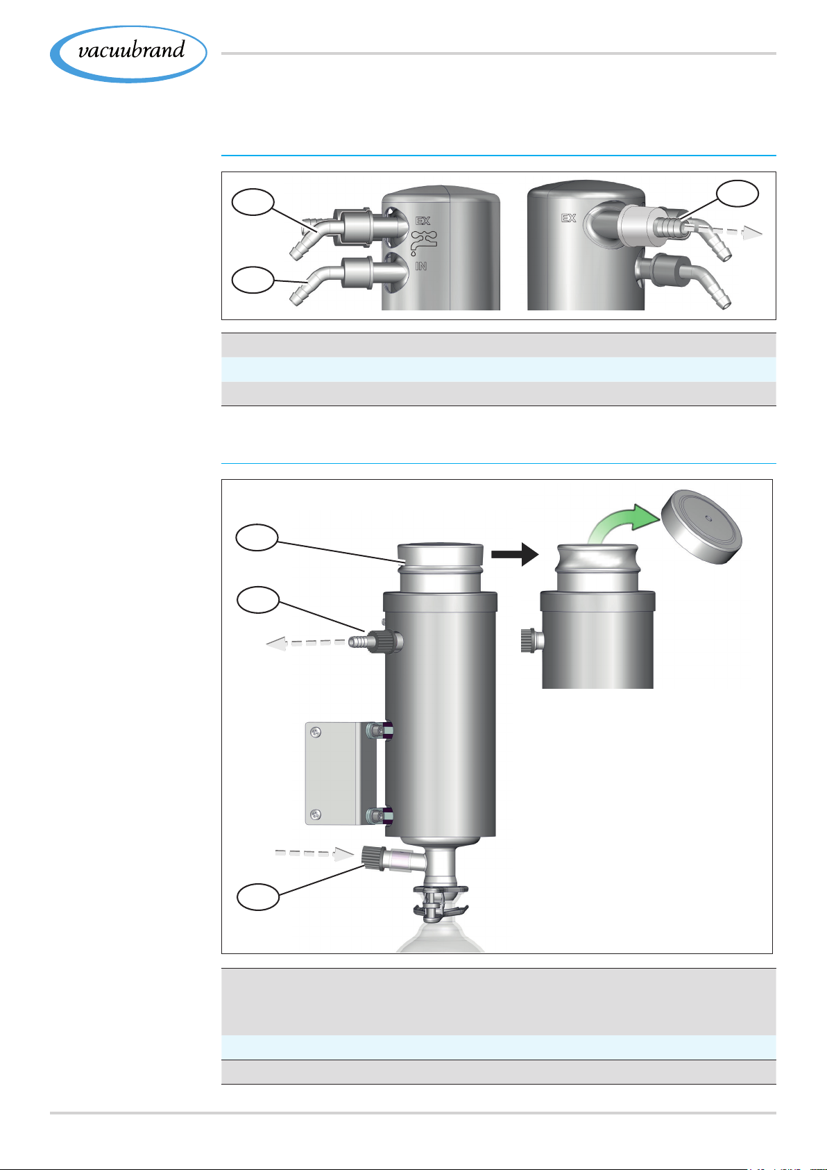
Product description
3.3.2 3.3.2 Condenser at the outletCondenser at the outlet
Connection and coolant at vapor condenser
Connections at the
EK
Meaning
Connections at TE
PC 3001 VARIO
select TE
7.2
7.3
7.1
Exhaust gas connection EX
7.2
Outlet connection coolant EX
7.3
Inlet connection coolant IN, e. g, water
Connection and coolant at dry ice condenser
7.4
7.1
Meaning
7.5
7.6
PC 3001 VARIO select TE
7.4
Opening for freezing mixture, e. g. dry ice mixture
Coolant insert can be removed for emptying, secured by bayo‑
net coupling
7.5
Exhaust gas connection EX
7.6
Connection from vacuum pump
2720901367_EN_PC3001_VARIO_select_Serie_V1.2_100220
Page 28
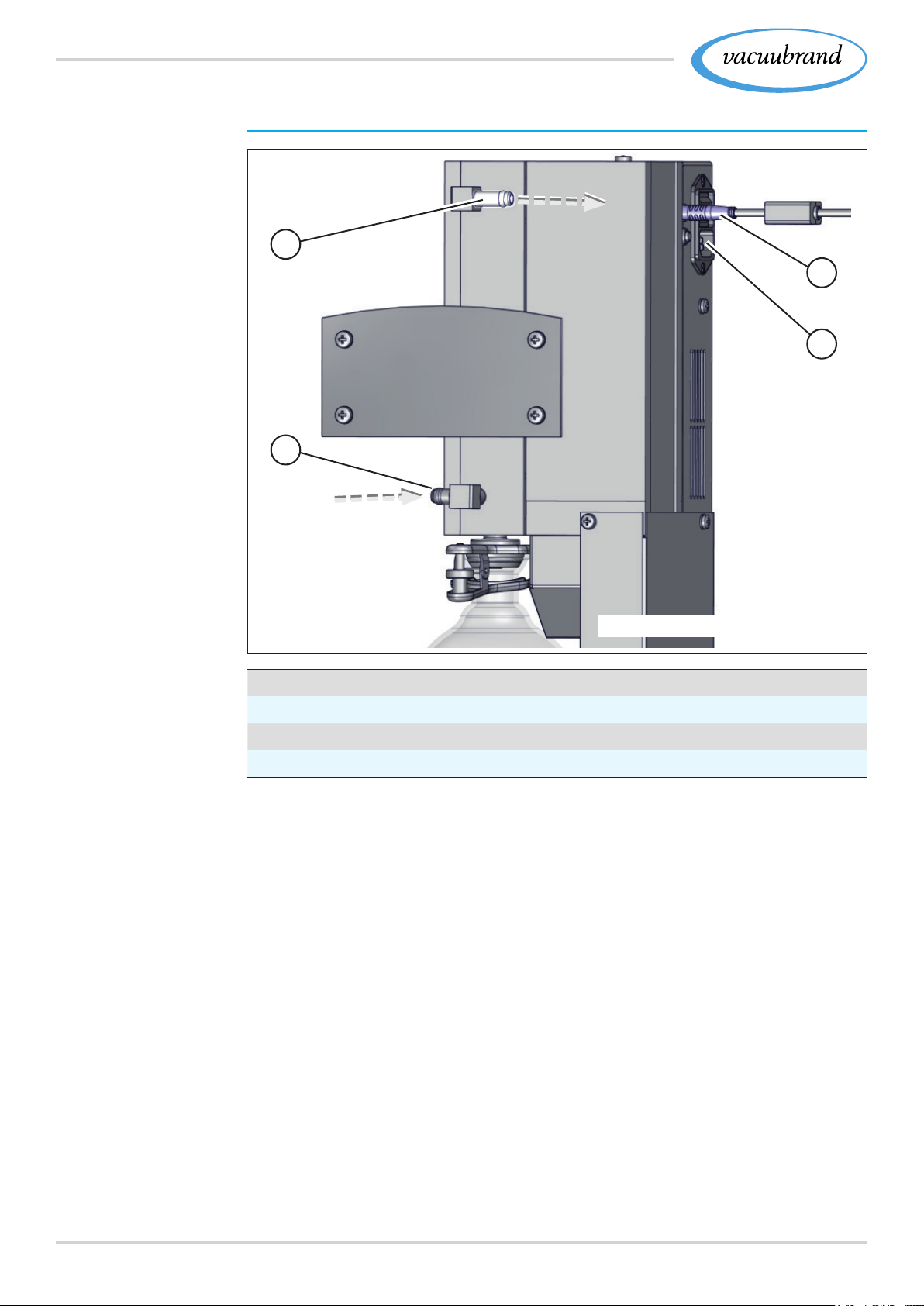
Product description
Connections on the Peltronic® emission condenser
Connections at the
EKP
1
2
3
4
Meaning
PC 3001 VARIO select EKP
1
Exhaust gas connection EX
2
Vacuum pump connection
3
VACUU·BUS® connection
4
To switch the gauge on/off with tools,
For detailed information on and descriptions of the Peltronic®
emission condenser, see manual #20901074.see manual #20901074.
28 20901367_EN_PC3001_VARIO_select_Serie_V1.2_100220
Page 29
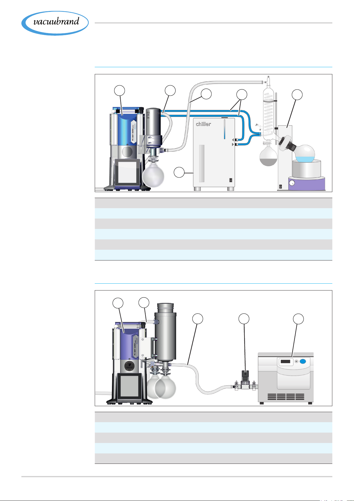
Example
Product description
3.4 3.4 Examples of useExamples of use
Evaporation
Rotary evaporation
Meaning
1
1
Vacuum pumping unit PC 3001 VARIO select
2
Exhaust gas hose (layed into a fume hood)
3
Chiller
4
Vacuum hose
5
Coolant hoses (connected in series)
6
Example of use: Rotary evaporator
2
3
4
5
6
Example
Vacuum concen‑
trator
Meaning
Vacuum concentrator
1
1
Vacuum pumping unit PC 3001 VARIO select TE
2
Exhaust gas hose (layed into a fume hood)
3
Vacuum hose
4
Vacuum valve: Shut‑off valve
5
Examples of use: Vacuum concentrator
2
3
4
5
2920901367_EN_PC3001_VARIO_select_Serie_V1.2_100220
Page 30
Installation and connection
4 4 Installation and connectionInstallation and connection
4.1 4.1 TransportTransport
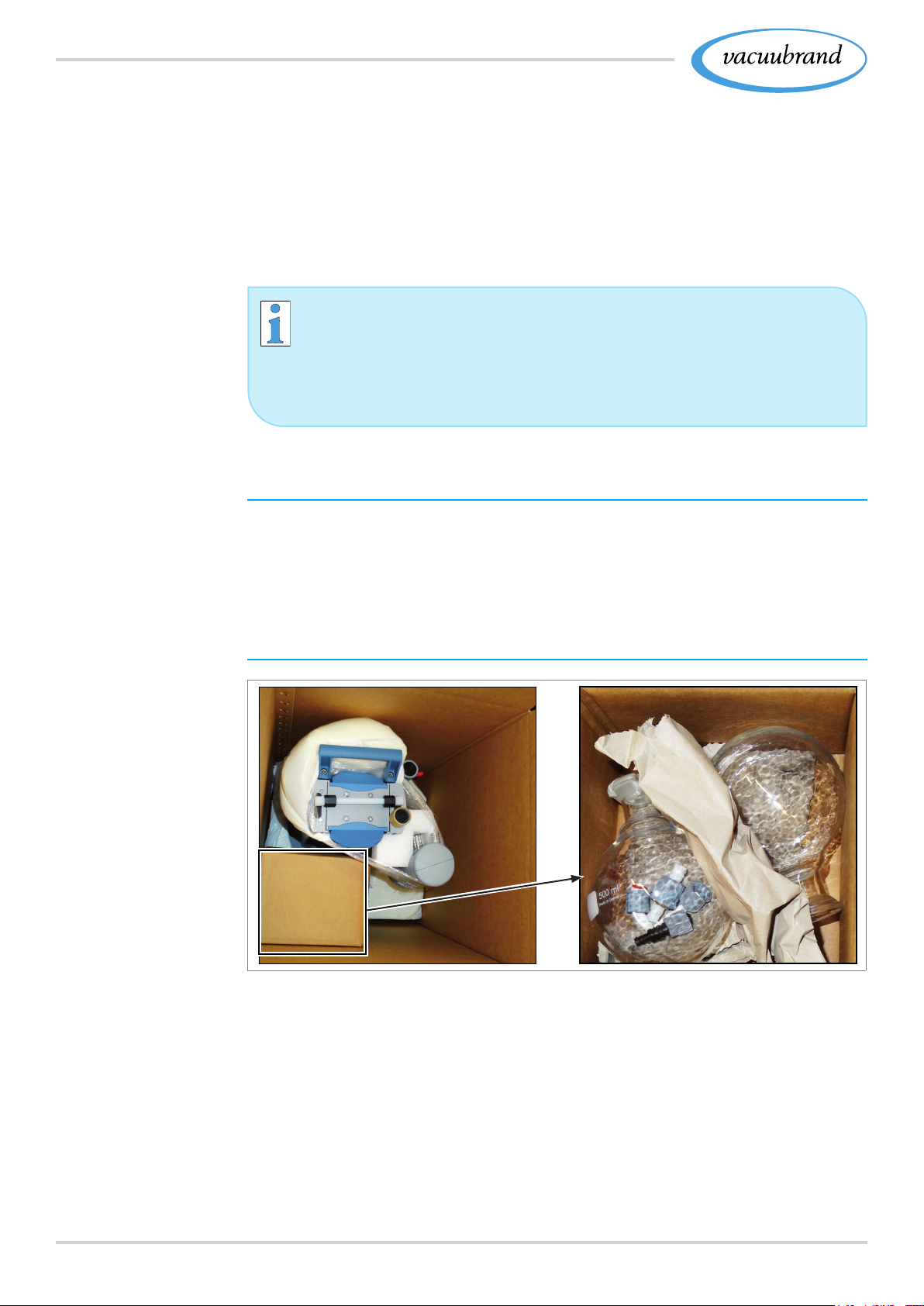
Products from VACUUBRAND are packed in sturdy, recyclable
packaging.
The original packaging is accurately matched to your
product for safe transport.
> If possible, please keep the original packaging, e. g., for
returning the product for repair.
Goods arrival
Example
Pumping unit in
original packaging
Glass ask in
enclosed box
Check the shipment for transport damage and completeness.
> Immediately report any transport damage in writing to the sup‑
plier.
Unpacking
> Lift the device only using the intended carrying handles or
recessed grips.
> Remove the connections, such as hose nozzles and screw
connections, out from the glass ask.
> Compare the scope of delivery with the delivery note.
30 20901367_EN_PC3001_VARIO_select_Serie_V1.2_100220
Page 31
Installation and connection
4.2 4.2 InstallationInstallation
NOTICENOTICE
Condensate can damage the electronics.
A large temperature difference between the storage location
and the installation location can cause condensation.
> After goods receipt or storage, allow your vacuum device to
acclimatize for at least 3‑4 hours before initial use.
Check installation conditions
Check installation
conditions
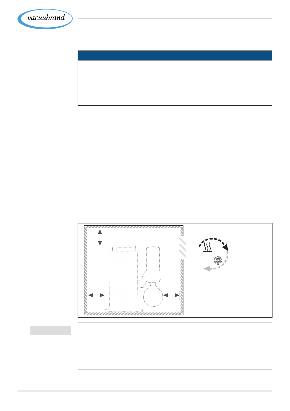
Example
Sketch
Minimum distances
in laboratory
furniture
The device is acclimatized.
Ambient conditions have been observed and are within the limi‑
tation of use.
The pump must have a stable and secure base without addi‑
tional mechanical contact apart from the pump feet.
Installing the vacuum pump
> Place the vacuum pump on a stable, nonvibrating, level, hori‑
zontal surface.
5 cm
IMPORTANT!
5 cm 5 cm
> When installing in laboratory furnishings, maintain a mini‑
mum distance of 5 cm (2 in.) from adjacent objects or sur‑
faces.
> Prevent heat accumulation and ensure sufcient air circula‑
tion, especially in closed housings.
3120901367_EN_PC3001_VARIO_select_Serie_V1.2_100220
Page 32
Installation and connection
Observe limitations of use
Observe limitation of
use
IMPORTANT!
Ambient conditions
Ambient temperature, max. 10–40 °C 50–104°F
Altitude, max.
Relative humidity 30–85 %, nicht betauend
Pollution degree 2
Impact energie 5 J
Protection type (IEC 60529) IP 20
Protection type (UL 50E) NEMA Type 1
Prevent condensation or contamination from dust, liquids, or corrosive
gases.
2000 m
above sea level
(US)
6562 ft
above sea level
> Note the IP protection class of the controller. IP protection is
only guaranteed if the device is appropriately installed and
correctly connected.
> For connection also note rating plate data and chapter
8.1.1 Technical data on page 74.8.1.1 Technical data on page 74.
4.3 4.3 ConnectionConnection
All condensers of the pumping unit series have a vacuum connec‑
tion and an exhaust gas connection. The connection is very simi‑
lar. Perform the connection for your pumping unit as described in
the examples below.
4.3.1 4.3.1 Vacuum connection (IN)Vacuum connection (IN)
CAUTION
Flexible vacuum hoses can contract during
evacuation.
Unsecured connected components can cause injuries or
damage due to jerky movement (shrinkage) of the exible
vacuum hose. The vacuum hose can come loose.
> Fix the vacuum hose to the connections.
> Fix connected components.
> Measure the exible vacuum hose such that you take
the maximum shrinkage into account.
32 20901367_EN_PC3001_VARIO_select_Serie_V1.2_100220
Page 33
Installation and connection
NOTICENOTICE
Foreign bodies in the suction line can damage the vacuum
pump.
> Prevent particles, liquids or contaminants from being aspi‑
rated or being able to ow back.
Connect vacuum hose
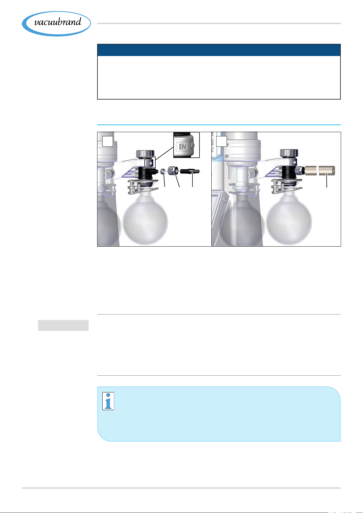
Vacuum connection
at the inlet IN
1 2
(c)(a) (b)
(d)
1. Connect the sealing ring (a), knurled nut (b) and hose noz‑
zle (c) as shown.
2. Push the vacuum hose (d) from the apparatus onto the hose
nozzle and secure the vacuum hose, for example, with a
hose clamp.
IMPORTANT!
> Use the vacuum hose which is designed for the vacuum
range used and which has sufcient stability.
> Connect hose lines as short as possible.
> Connect hose lines in a gas‑tight manner to the vacuum
pump.
Please observe the following points to get an optimal
result:
> Connect a vacuum line as short as possible with a cross‑
section as wide as possible.
3320901367_EN_PC3001_VARIO_select_Serie_V1.2_100220
Page 34
Installation and connection
4.3.2 4.3.2 Exhaust gas connection (EX)Exhaust gas connection (EX)
WARNING
Risk of bursting due to overpressure inside the
exhaust tube.
Inadmissibly high pressure in the exhaust gas line can
cause the vacuum pump to burst or damage seals.
> The exhaust gas line (outlet, gas outlet) must always
be clear and non‑pressurized.
> Always position the exhaust gas hose downwards or
take measures to prevent condensate from owing
back into the vacuum pump.
> Observe the maximum admissible pressures and
pressure differences.
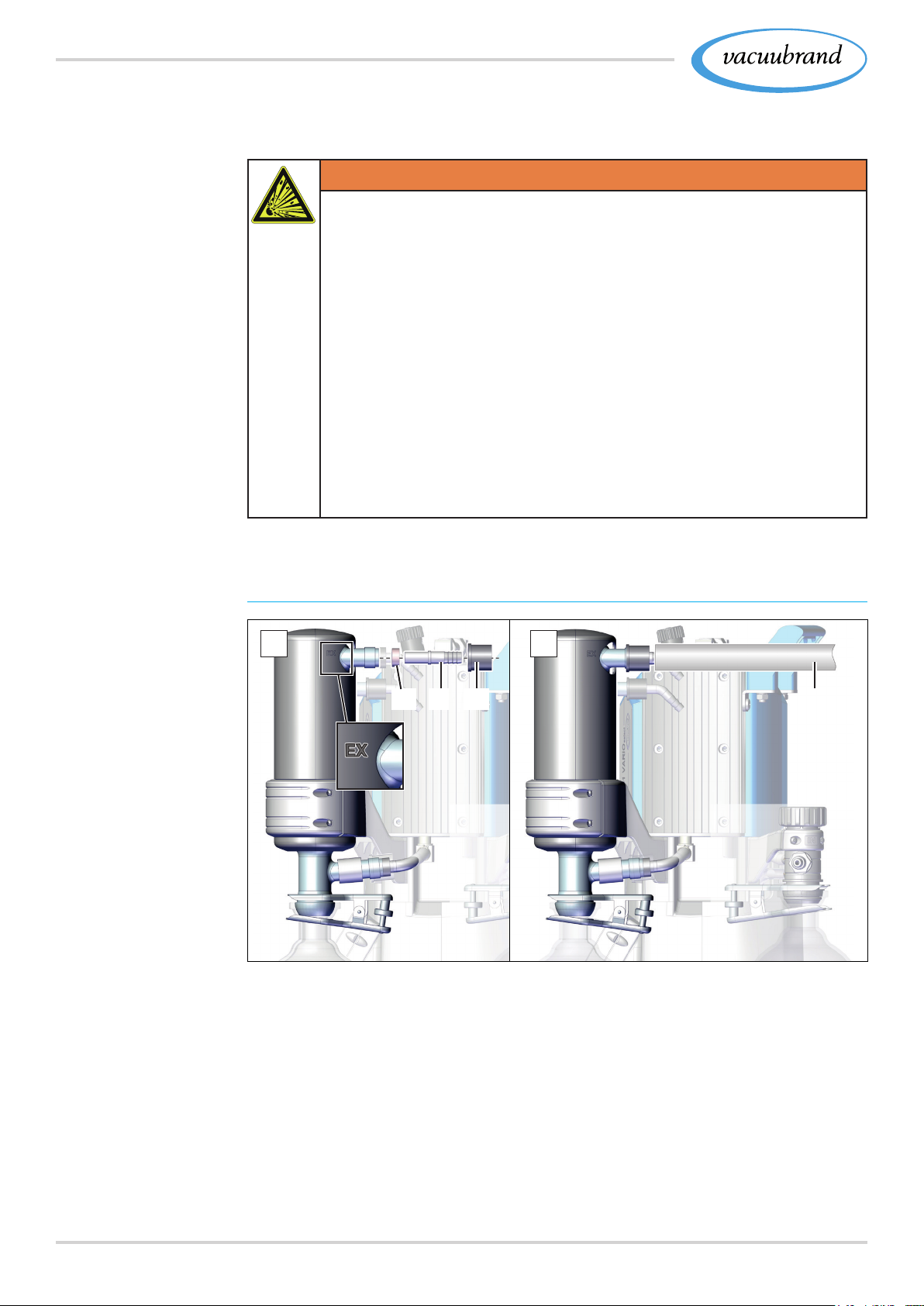
Example
Exhaust gas connec‑
tion at the outlet EX
Conntect exhaust gas hose
1 2
(g)(e) (f) (h)
1. Connect the sealing ring (e), the hose nozzle (f) and the
knurled nut (g) as shown and screw this onto the connection.
2. Push the exhaust gas hose (h) onto the hose nozzle and lay
the hose, if necessary, in a fume hood. If necessary x the
vacuum hose, e. g., with a hose clamp.
34 20901367_EN_PC3001_VARIO_select_Serie_V1.2_100220
Page 35
Installation and connection
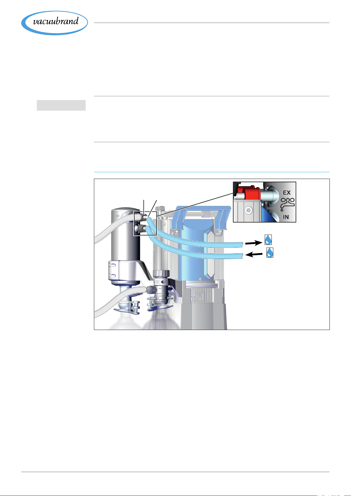
4.3.3 4.3.3 Coolant connection at the condenserCoolant connection at the condenser
Coolant connection
IN = Feed line
EX = outlet
IMPORTANT!
Example
Coolant connection
at the EK or IK
Both an emission condenser EK and an immission condenser IK
have a connection for coolant liquids. Water or the liquid from,
e. g., a chiller are suitable for cooling.
In a closed, in‑house cooling water circuit, the pressure should
be limited to 3 bar (44 psi).
A cooling water valve may only be installed in the intake; the
coolant drainage must be clear and non‑pressurized.
Connect coolant
(i) (j)
EX
IN
1. Fix both hose nozzles (i) to the condenser as shown using
the knurled nut (j).
2. Fix the hoses for the coolant on the condenser as shown.
IN = inlet, e. g., from rotary evaporator,
EX = outlet, e. g., to chiller.
3. Fix the vacuum hoses, e. g., with hose clamps.
3520901367_EN_PC3001_VARIO_select_Serie_V1.2_100220
Page 36
Installation and connection
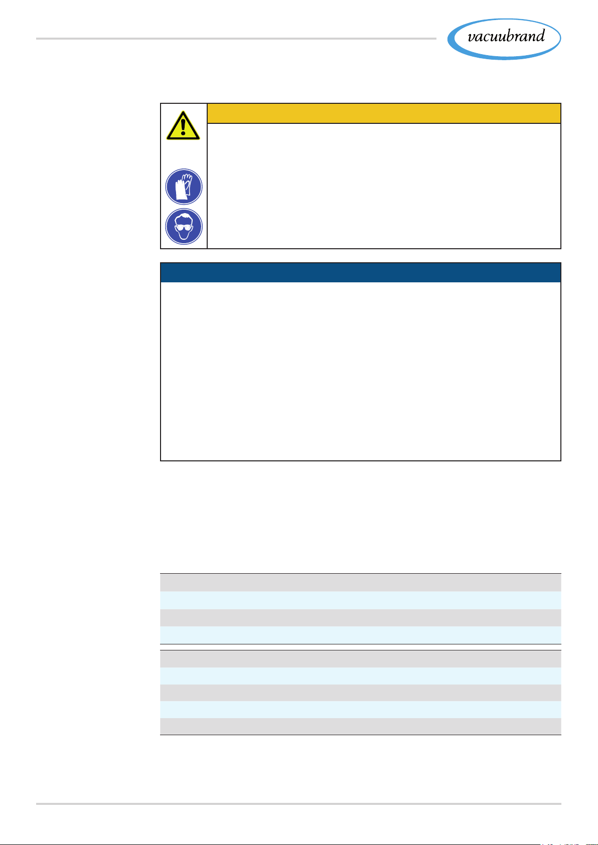
4.3.4 4.3.4 Dry ice condenserDry ice condenser
CAUTION
Risk of injury when handling cryogenic coolants.
Cryogenic materials can cause frostbite, also known as
cold burns, upon contact with skin.
> Avoid skin contact and always wear your personal pro‑
tective equipment when handling cryogenic substances,
e. g., protective gloves against thermal risk, protective
goggles
NOTICENOTICE
Damage to the dry ice condenser due to cryogenic
materials.
Cooling with dry ice
condenser
Information
coolant mixtures
> Always perform a visual inspection before each use,. The
surfaces of the glass must be free of damage, ruptures,
cracks or scratches.
> Only place the lid on the dry ice condenser and ensure
pressure equalization between the coolant and the atmo‑
sphere.
> The coolant may unexpectedly escape from the cooler, e.
g., in the event of a signicant volume of gas.
The dry ice condenser has no coolant connection. The dry ice
cooler is lled with a freezing mixture for cooling. These freezing
mixtures consist of cold to cryogenic media and a liquid for better
transfer of cold.
Coolant mixtures (examples)
Ethanol‑dry ice mixture
Water‑ice mixture
Saltwater‑ice mixture
Permissible chill temperatures
cold ‑5 – ‑18 °C 23 – ‑0.4 °F
very chilly ‑18 – ‑30 °C 0.4 – ‑22 °F
cryogenic below ‑30 °C less than ‑22 °F
lowest ‑80 °C ‑.112 °F
36 20901367_EN_PC3001_VARIO_select_Serie_V1.2_100220
(US)
Page 37
Installation and connection
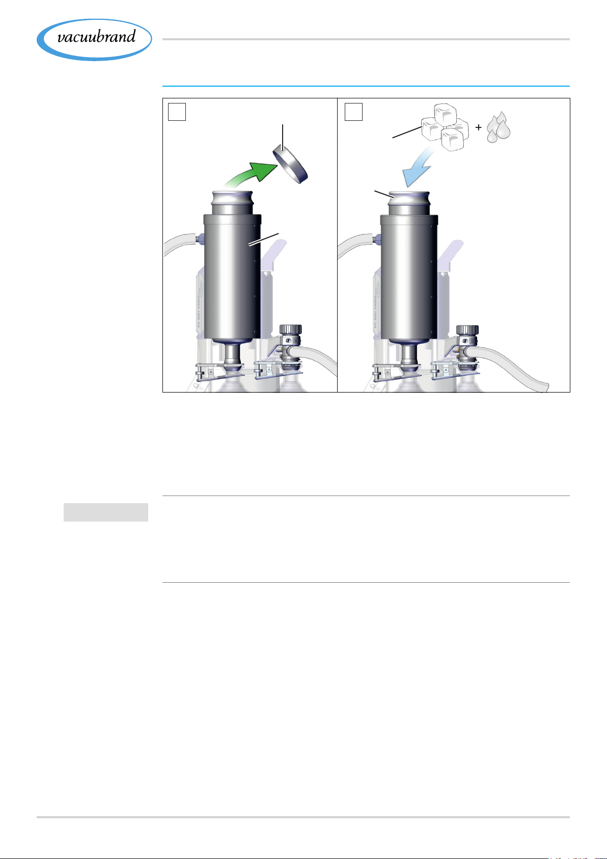
Fill dry ice condenser
Example
Fill dry ice
condenser with
freezing mixture
1
(k)
(l)
2
(m)
(n)
IMPORTANT!
1. Take the lid (k) off of the dry ice condenser (l).
2. Fill your preferred freezing mixture (m) into the
container (n).
3. Then place the lid back on the dry ice condenser.
> Do not overll the container.
> Always place the lid on; do not x it.
> Regularly check the coolant level in the cooler during opera‑
tion.
3720901367_EN_PC3001_VARIO_select_Serie_V1.2_100220
Page 38
Installation and connection
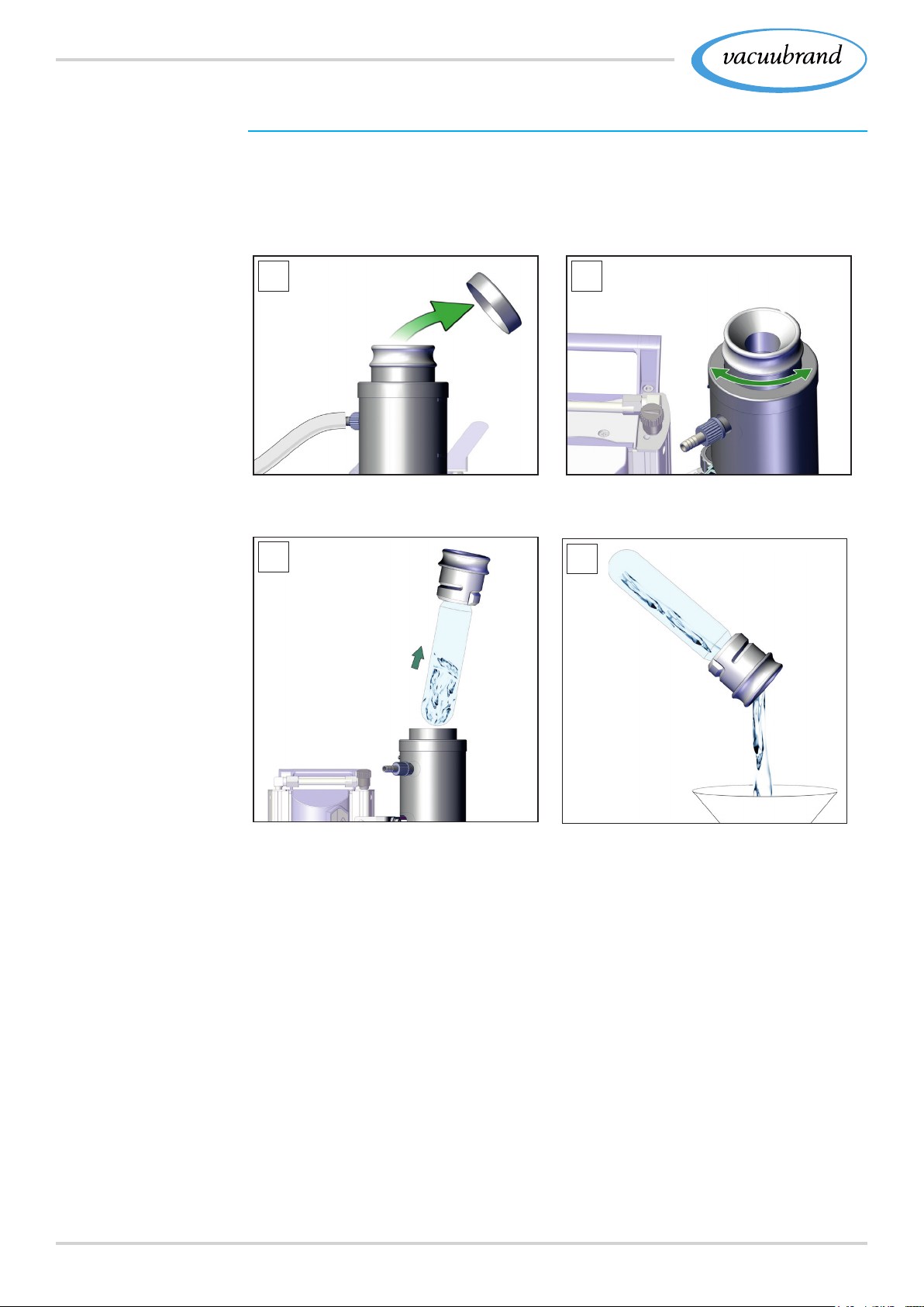
Empty dry ice condenser TE
Before relling the dry ice condenser with coolant, it may have to
be emptied rst. Remove and empty cooler insert (bayonet cou‑
pling).
Cooler insert
(bayonet coupling)
1 2
1. Take the lid off of the cooler. 2. Turn the coolant insert – bayo‑
net lock.
3
4
3. Pull out the container. 4. Drain the liquid.
5. Put the empty container back into the dry ice condenser in
reverse sequence.
38 20901367_EN_PC3001_VARIO_select_Serie_V1.2_100220
Page 39
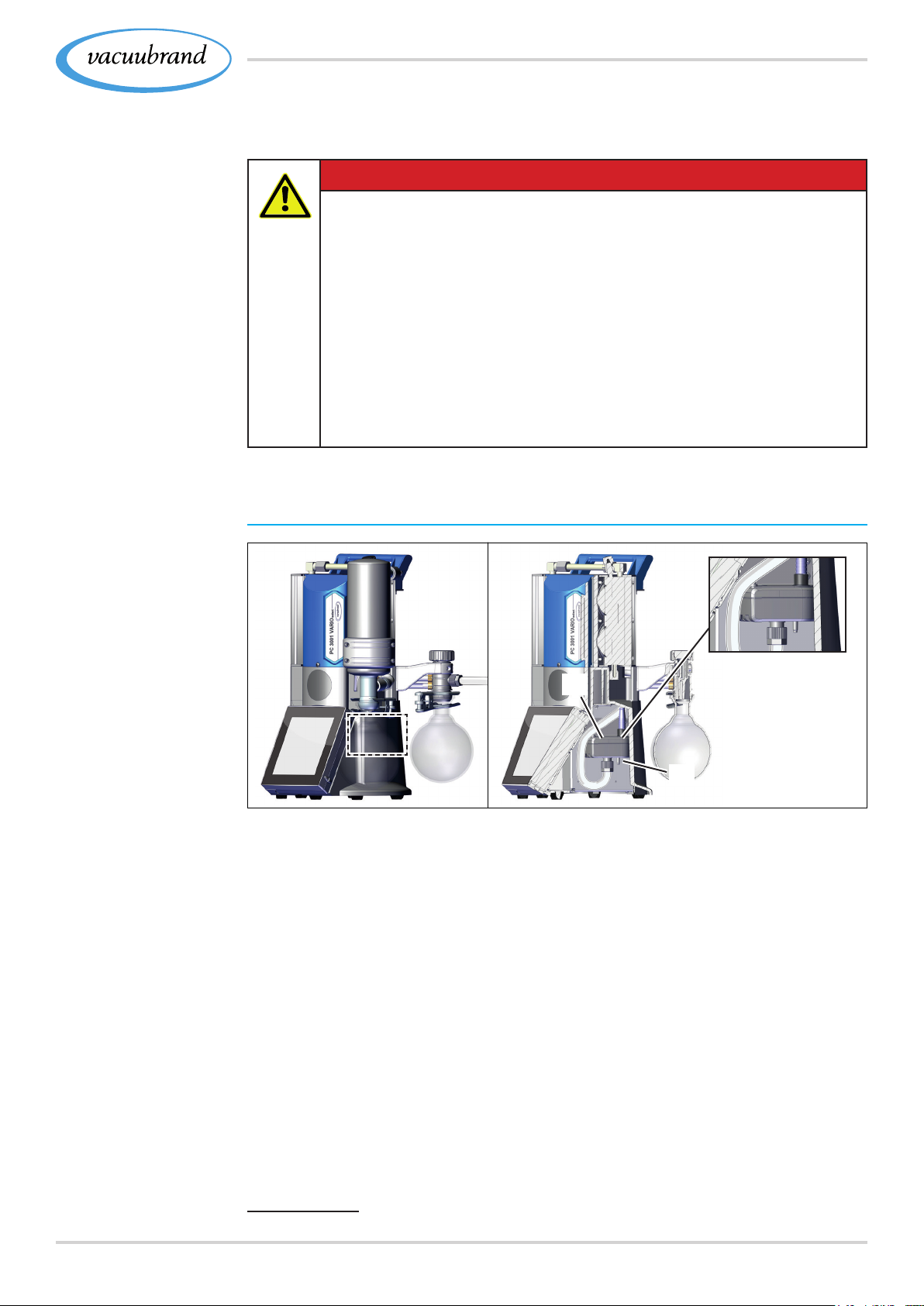
Installation and connection
4.3.5 4.3.5 Venting connectionVenting connection
DANGERDANGER
Risk of explosion due to venting with air.
Depending on the application, venting can cause explo‑
sive mixtures to form or other hazardous situations to
arise.
> Never vent processes with air which could form an
explosive mixture.
> In the case of ammable substances, use
only inert gas for venting, e. g., nitrogen
(max. 1.2 bar/900 Torr abs.).
Position of sensor
+ venting valve
cutaway sketch
Venting with ambient air
1
(o)
(p)
For venting (p) with ambient air, nothing needs to be connected to
the sensor (o).
1 Only valid for sensors with integrated venting valve.
3920901367_EN_PC3001_VARIO_select_Serie_V1.2_100220
Page 40
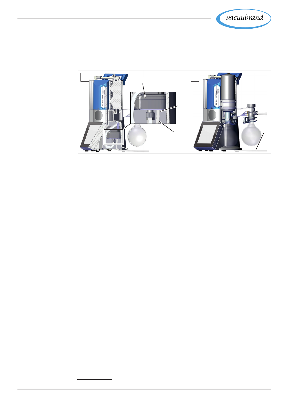
Installation and connection
Position of sensor
+ venting valve
connection cutaway
drawing
Venting with inert gas – connect venting valve
2
Required connection material: Hose for hose nozzle (Ø 4–5 mm),
e. g., silicone hose 3/6 mm.
1 2
(o)
(p)
(q)
(q)
1. Tilt the pumping unit slightly to the side and attach the
hose (q) to the connection of the venting valve (p) at the sen‑
sor (o).
2. Lay the hose under the pumping unit outwards and connect
the inert gas (max. 1.2 bar/ 900 Torr, abs.).
2 Avoid overpressure.
40 20901367_EN_PC3001_VARIO_select_Serie_V1.2_100220
Page 41
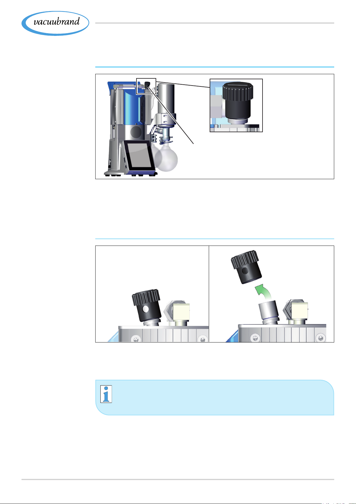
Position of gas
ballast valve
Installation and connection
4.3.6 4.3.6 Gas ballast (GB)Gas ballast (GB)
Use ambient air as gas ballast
(r)
If ambient air is to be used as gas ballast, nothing must be
connected at the pumping unit; gas ballast valve (r) see also
chapter 5.2.2 Operation with gas ballast on page 475.2.2 Operation with gas ballast on page 47
Prepare inert gas
connection (GB)
Use inert gas as gas ballast – OPTION
> Remove the black gas ballast cap and connect a gas ballast
adapter in its place.
You will receive connection options and adapters for hose
nozzles or a small ange from us upon request.
4120901367_EN_PC3001_VARIO_select_Serie_V1.2_100220
Page 42
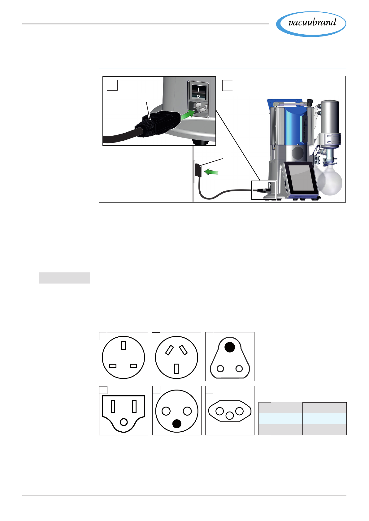
Installation and connection
4.3.7 4.3.7 Electrical connectionElectrical connection
Connect pumping unit electrically
Example
Electrical connection
pumping unit
1
(s)
2
(t)
1. Insert the connector (s) of the power cable in the power con‑
nection of the vacuum pump.
2. Plug the wall power supply (t) into the mains socket.
5 Pumping unit connected electrically.
IMPORTANT!
Diagrams of
standard power
connections with
grounding contact
> Lay the connection cable such that it cannot be damaged by
sharp edges, chemicals, or hot surfaces.
Mains (power) connections with country code
1
4
2
5 6
3
1 UK 4 US
2 CN 5 CEE
3 IND 6 CH
The vacuum pump is delivered with the appropriate power plug,
ready for use.
42 20901367_EN_PC3001_VARIO_select_Serie_V1.2_100220
Page 43

Installation and connection
IMPORTANT!
> Use the power plug which ts your power supply.
> Do not use multi‑outlet power strips connected in series as
the power connection.
> The mains plug is a disconnecting device to separate the
pump from the supply voltage. Ensure that the mains plug is
easily accessible at all times to allow the separation of the
device from the power supply.
4320901367_EN_PC3001_VARIO_select_Serie_V1.2_100220
Page 44
Initial use (operation)
5 5 Initial use (operation)Initial use (operation)
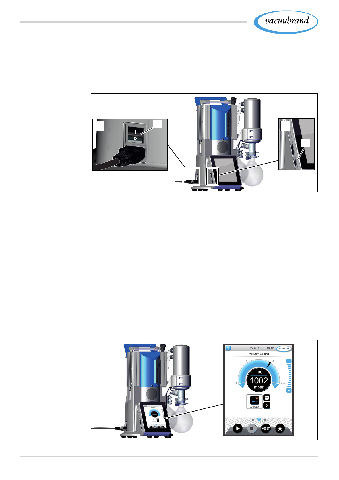
5.1 5.1 Switch onSwitch on
Switch on pumping unit
Switch on pumping
unit
Operation by
vacuum controller
1
(a)
2
(b)
1. Switch the rocker switch (a) on – switch position I.
2. Press ON/OFF button (b) at the controller.
5 Display with start screen.
5 After approx. 30 seconds, the process screen appears
with the operating elements in the controller display.
5.2 5.2 Operation Operation
This manual contains – apart from the chapters Switching on and
Switching off – the mechanical description of the pumping unit of
the PC 3001 VARIO select series.
The operation of the installed vacuum controller and its functions
are described in its own manual VACUU·SELECT.
44 20901367_EN_PC3001_VARIO_select_Serie_V1.2_100220
Page 45
Process screen
Initial use (operation)
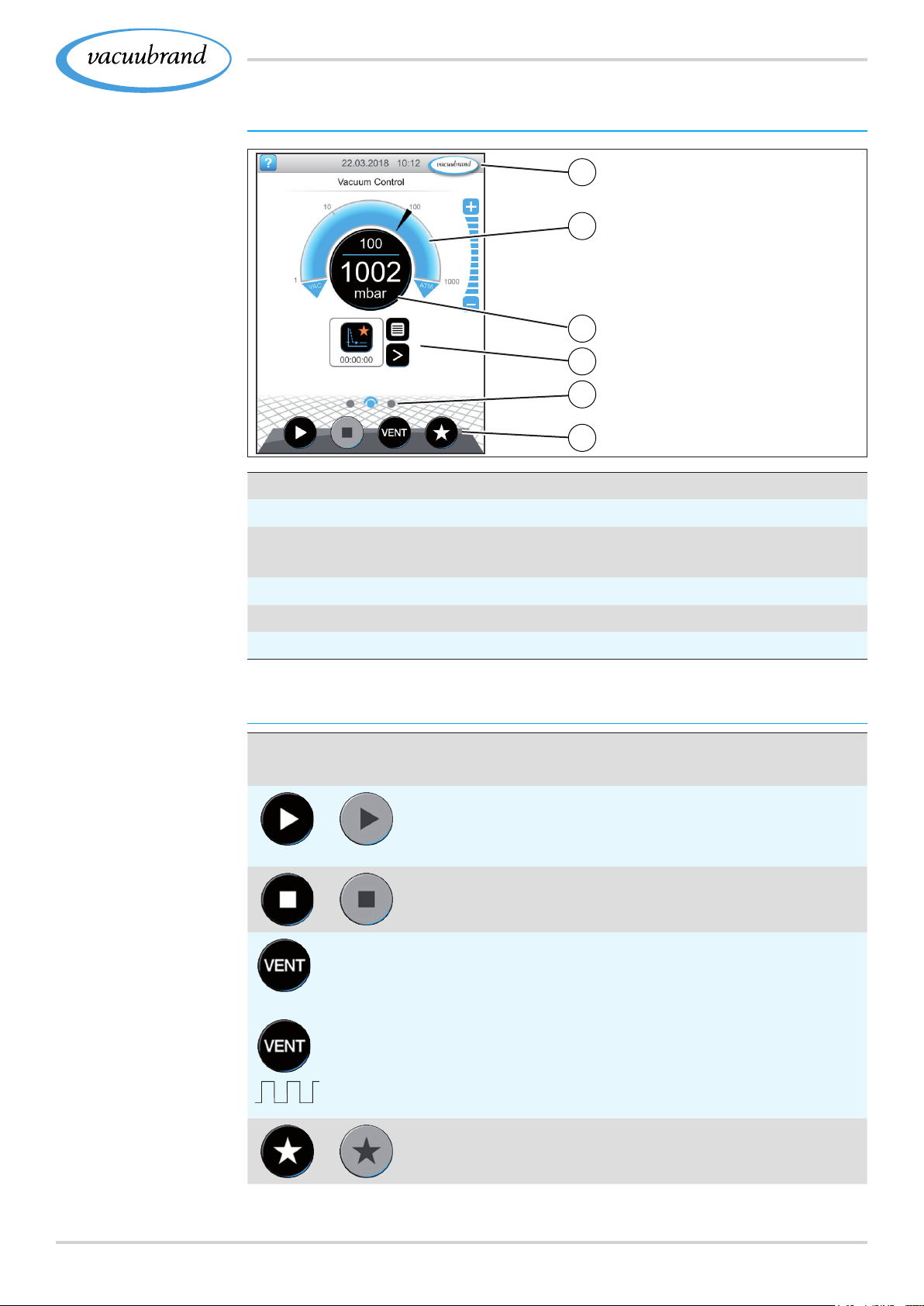
Process screen
vacuum controller
1
2
3
4
5
6
1
Status bar
2
Analogue pressure reading – pressure curve
3
Digital pressure reading – pressure value
(target value, actual value, pressure unit)
4
Process screen with context functions
5
Screen navigation
6
Operating elements for control
Operating elements
vacuum controller
Operating elements
Button
active locked
*
*
Function
StartStart
` Start application – only available on the process
screen.
StopStop
` Stop application – always possible.
VENTVENT – vent the system (option)
` Press button < 2 sec = momentarily vent; control
continues.
` Press button > 2 sec = vent to atmospheric pres‑
sure; vacuum pump is stopped.
` Press button during venting = venting is stopped.
FavoritesFavorites
` View Favorites menu.
* Button is only displayed if venting valve is connected or activated.
4520901367_EN_PC3001_VARIO_select_Serie_V1.2_100220
Page 46
Initial use (operation)
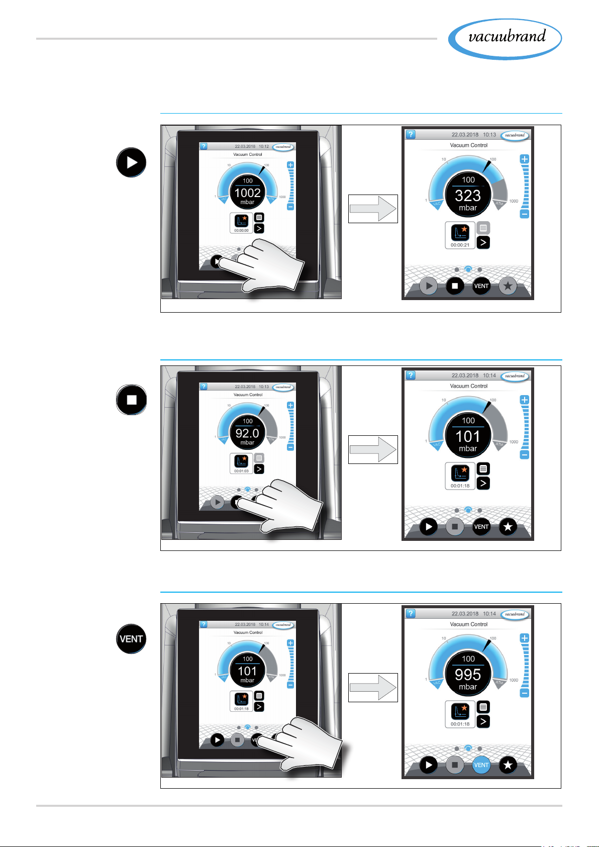
5.2.1 5.2.1 OperationOperation ( ( see description of controller) see description of controller)
Start the vacuum controller
Start
Stop
Venting
Stop the vacuum controller
Venting
46 20901367_EN_PC3001_VARIO_select_Serie_V1.2_100220
Page 47
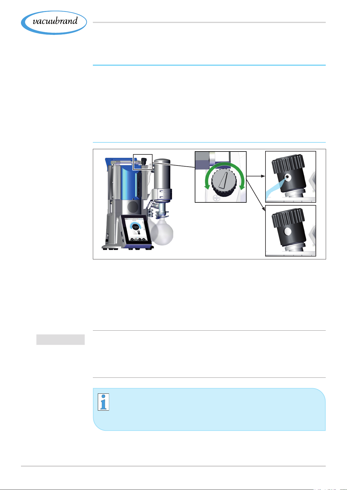
Operate gas ballast
valve
Initial use (operation)
5.2.2 5.2.2 Operation with gas ballastOperation with gas ballast
Meaning
The provision of gas ballast (= addition of gas) ensures that vapors
do not condense inside the vacuum pump but are instead ejected
from the pump. This makes it possible to pump larger amounts of
condensable vapors and service lives are prolonged. The ultimate
vacuum with gas ballast is slightly higher.
Open/close gas ballast valve
IMPORTANT!
ON
OFF
> Turn the black gas ballast cap in any direction to open or
close the gas ballast valve.
> Evacuate condensable vapors, e. g., water vapor, solvents,
etc. preferably only with the vacuum pump at operating tem‑
perature and with the gas ballast valve open.
> Connect inert gas as a gas ballast, if necessary, to exclude
the formation of explosive mixtures.
> Observe the admissible pressure at the gas ballast connec‑
tion, max. 1.2 bar/900 Torr abs.
If the gas volume in the vacuum pump is low, a gas ballast
can, where appropriate, be eliminated in these cases in
order to increase the solvent recovery rate.
4720901367_EN_PC3001_VARIO_select_Serie_V1.2_100220
Page 48
Initial use (operation)
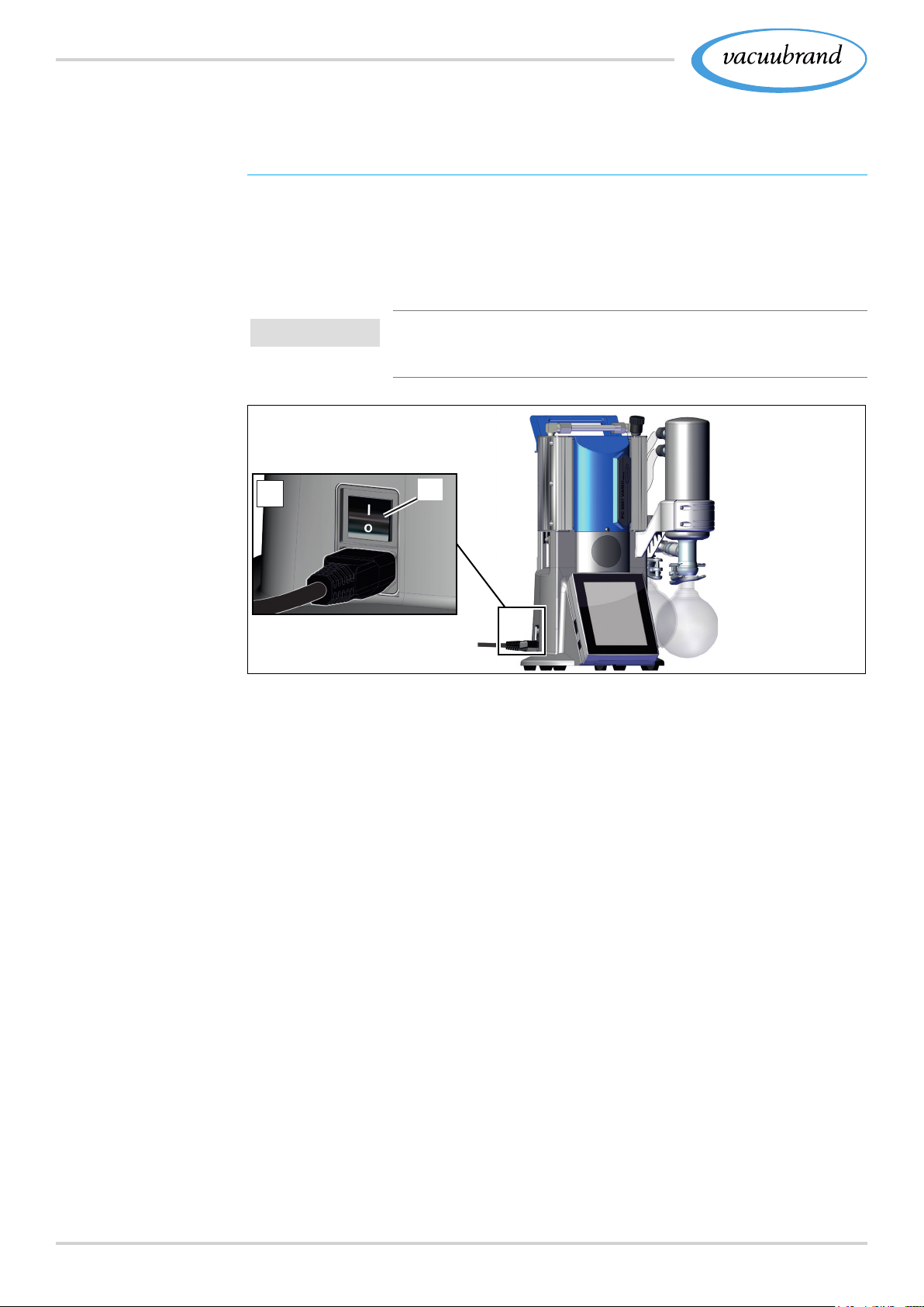
5.3 5.3 Decommissioning (switch off)Decommissioning (switch off)
Take pumping unit out of operation
Switch‑off pumping
unit
1. Stop the process and allow the pumping unit to run for
approx. 30 minutes, with open gas ballast or open inlet (IN).
5 Condensate and residual media are rinsed from the vacu‑
um pump.
IMPORTANT! > Prevent deposits and rinse condensate out of
the pump.
2
(a)
2. Switch the rocker switch (a) off – switch position O.
5 Pumping unit switched off.
3. Disconnect the pumping unit from the apparatus.
4. Empty the glass asks.
5. Check the pumping unit for possible damage and pollution.
48 20901367_EN_PC3001_VARIO_select_Serie_V1.2_100220
Page 49

Initial use (operation)
5.4 5.4 StorageStorage
Store pumping unit
1. Clean the vacuum pumping unit when it is polluted.
2. Recommendation: Perform a preventive maintainance before
storing the pumping unit. Especially if it ran more than 15000
operating hours
3. Close the suction and exhaust connections, e. g., with protec‑
tion caps.
4. Package the pumping unit such that it is protected from dust;
possibly
enclose desiccants.
5. Store the vacuum pumping unit in a cool, dry location.
IMPORTANT!
If damaged parts are stored for operational reasons, these should
be clearly identied as not ready for use.
4920901367_EN_PC3001_VARIO_select_Serie_V1.2_100220
Page 50
Troubleshooting
6 6 TroubleshootingTroubleshooting
6.1 6.1 Technical supportTechnical support
> To identify errors and potential remedies, please refer to the
troubleshooting table Error – Cause – RemedyError – Cause – Remedy.
For technical assistance or errors for which you require additional
support, please contact your local distributor or our Service De‑
partment
1
.
Operate the machine only when it is in proper working
condition.
> Observe the recommended maintenance intervals and thus
ensure a functional system.
> Send defective devices to our Service Department or your
local supplier for repair!
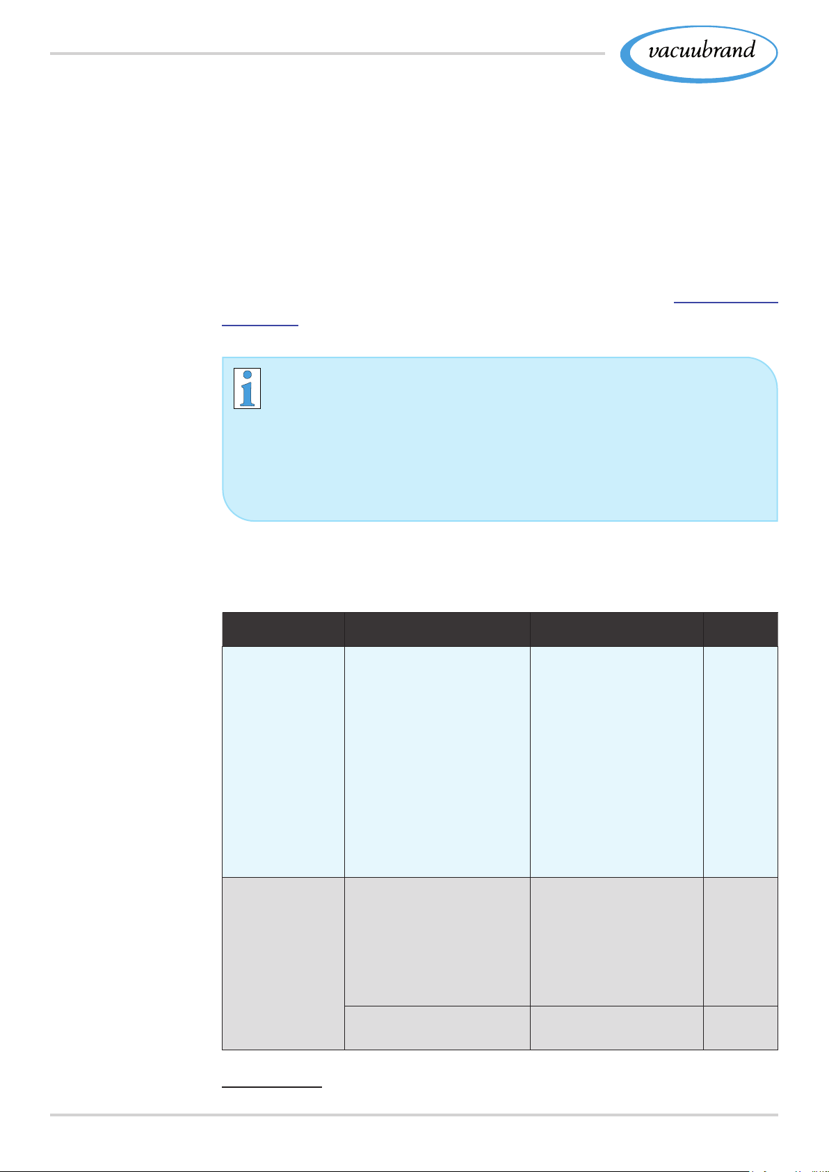
6.2 6.2 Error – Cause – RemedyError – Cause – Remedy
ErrorError ` Possible cause 3Remedy
Readings
deviate from
the reference
standard
Sensor does
not pass on
measured val‑
ue
` Vacuum sensor pol‑
luted.
` Moisture in the sen‑
sor
` Defective sensor.
` Sensor measures
incorrectly.
` No voltage applied.
` VACUU·BUS plug‑in
connection or cables
defective or not con‑
nected.
3 Clean sensor mea‑
suring chamber.
3 Allow sensor mea‑
suring chamber to
dry, e. g., through
pumping.
3 Calibrate sen‑
sor with reference
gauge.
3 Replace defective
parts.
3 Check VACUU·BUS
plug‑in connection
and cables to the
controller.
Personnel
Specialist
Operator
Defective sensor. 3 Replace defective
`
parts.
1 -> Phone: +49 9342 808-5660, fax: +49 9342 808-5555, [email protected]
50 20901367_EN_PC3001_VARIO_select_Serie_V1.2_100220
Specialist
Page 51
Troubleshooting
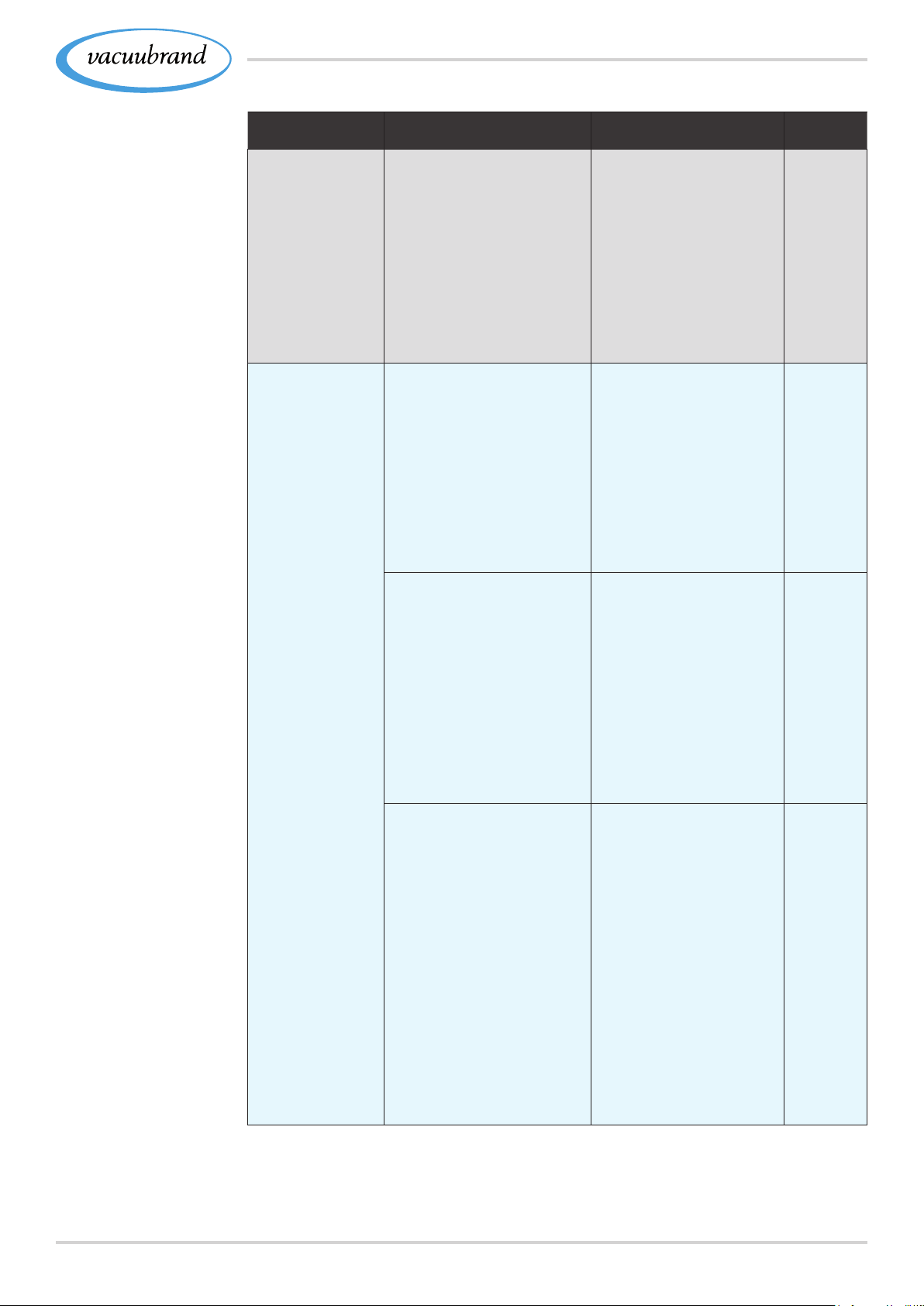
ErrorError ` Possible cause 3Remedy
Venting valve
does not oper‑
ate
Vacuum pump
does not start.
` No voltage applied.
` VACUU·BUS plug
connection or cables
defective or not con‑
nected.
` Venting valve pol‑
luted.
` Venting valve inside
the sensor defective.
` Overpressure in the
exhaust gas line.
` Condensation in the
vacuum pump.
Pumping unit
`
switched off.
` Power plug or plug‑in
power supply not cor‑
rectly plugged in or
pulled out.
` VACUU·BUS plug
connection or cables
defective or not con‑
nected.
`
Motor overloaded.
` Thermal protection
triggered.
3 Check VACUU·BUS
plug connection and
cables to the con‑
troller.
3 Clean venting valve.
3 If necessary, use
another external
venting valve.
3 Open up exhaust
gas line.
3 Ensure a clear pas‑
sage.
3 Flushing: Oper‑
ate vacuum pump
briey with open
suction nozzle and
max. speed.
3 Switch pumping
unit on using rocker
switch.
3 Check power supply
and cable.
3 Check VACUU·BUS
plug connection and
cables to the con‑
troller.
3 Check coolant con‑
nection.
3 Ensure coolant sup‑
ply.
3 Allow the motor to
cool off.
3 Reset error manu‑
ally:
Unplug pumping
unit from mains
Eliminate cause
of error
Switch pumping
unit back on.
Personnel
Specialist
Operator
Operator
Specialist
5120901367_EN_PC3001_VARIO_select_Serie_V1.2_100220
Page 52
Troubleshooting
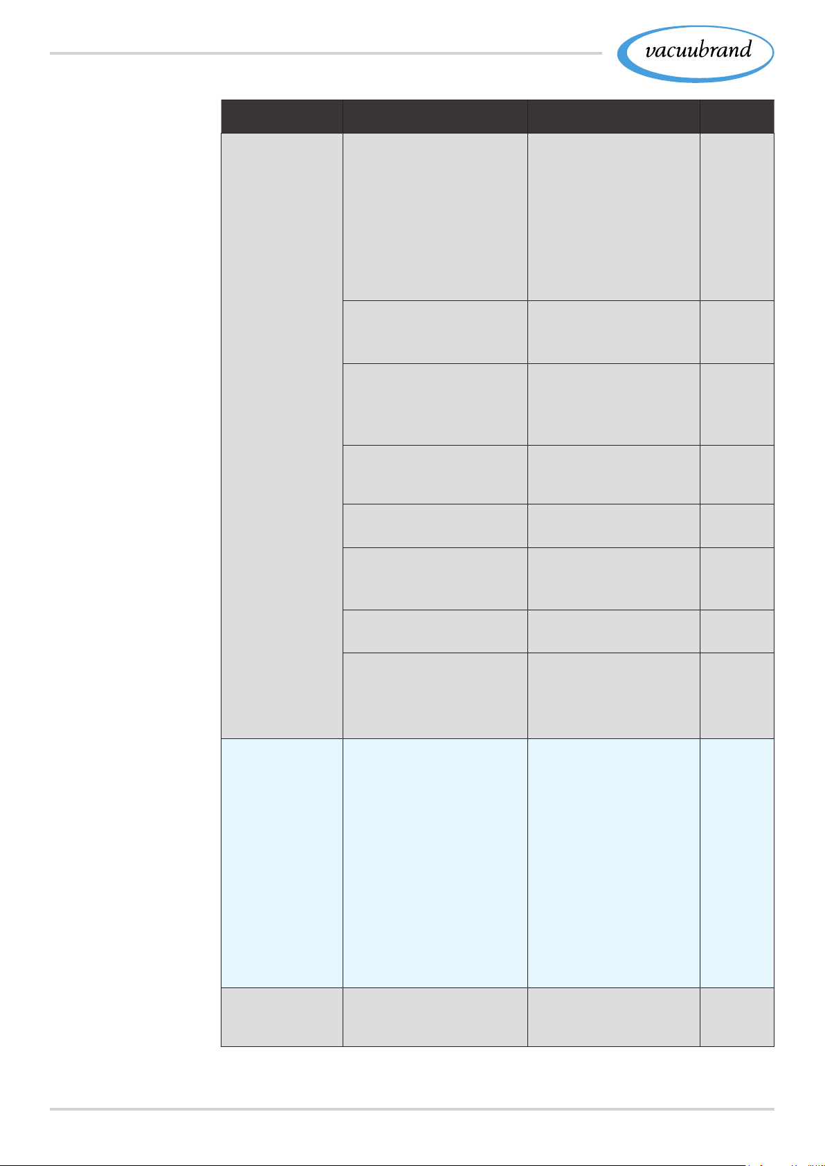
ErrorError ` Possible cause 3Remedy
No or very little
suction power
` Leak in the suction
line or in the appara‑
tus.
` Condensate col‑
lection bottle not
mounted properly.
3 Check suction line
and system for pos‑
sible leaks.
3 Check condensate
ask and its cor‑
rectly xation.
3 Check apparatus for
leaks.
Vacuum line too long. 3 Use vacuum lines
`
with a larger cross‑
section.
Condensate inside
`
the vacuum pump.
3 Allow vacuum pump
to run for a few min‑
utes with the suction
nozzle open.
Deposits inside the
`
vacuum pump
3 Clean and check
pump heads.
Personnel
Operator
resp. Specialist
Operator
Specialist
`
Diaphragms or valves
defective.
`
High level of vapor
generated in the pro‑
cess.
Gas ballast open 3 Close gas ballast
`
Gas ballast cap
`
porous or no longer
present.
No display ` Pumping unit
switched off.
` Power plug or plug‑in
power supply not cor‑
rectly plugged in or
pulled out.
` VACUU·BUS plug
connection or cables
defective or not con‑
nected.
` Controller switched
off or defective.
Loud operating
` No hose installed. 3 Check hose and
noises
3 Replace defective
parts.
3 Check process
parameter.
3 Check gas ballast
cap.
3 Replace defective
parts.
3 Switch pumping
unit on using rocker
switch.
3 Check power supply
and cable.
3 Check VACUU·BUS
plug connection and
cables to the con‑
troller.
3 Replace defective
parts.
install it right.
Specialist
Specialist
Operator
Operator
Operator
Operator
52 20901367_EN_PC3001_VARIO_select_Serie_V1.2_100220
Page 53
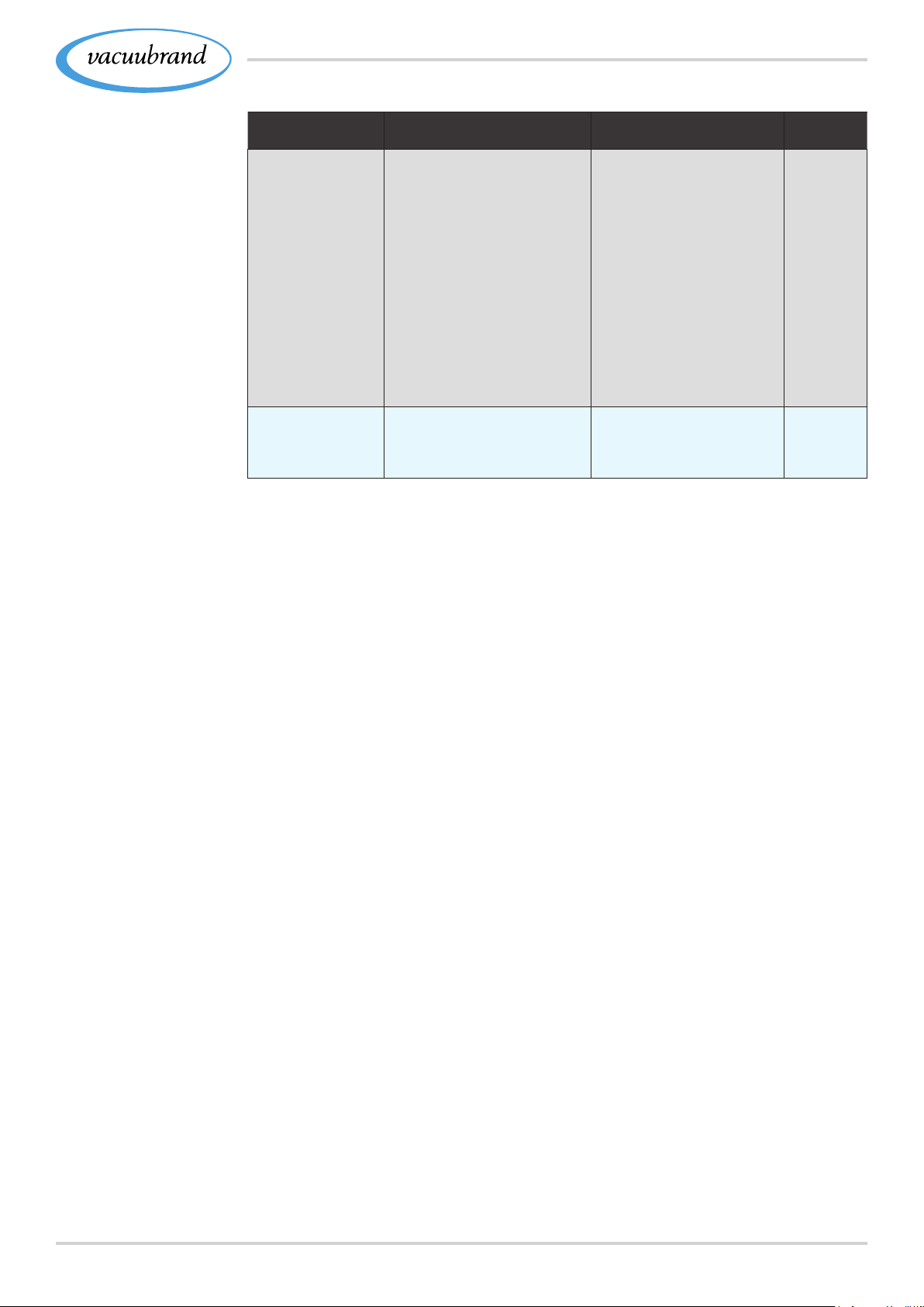
Troubleshooting
ErrorError ` Possible cause 3Remedy
Loud operating
noises
Condenser
(cooler) defec‑
tive
` Ball bearing defec‑
tive.
` Outlet pipe open.
` Mechanically
damaged.
3 Maintain vacuum
pump and replace
defective parts.
3 Check exhaust gas
line connections.
3 Connect the outlet
pipe to an exhaus‑
tion system, e. g.,
fume hood.
3 Glass ask on EK
missing.
3 Send in.
Personnel
Specialist
resp. Specialist
5320901367_EN_PC3001_VARIO_select_Serie_V1.2_100220
Page 54
Cleaning and maintenance
7 7 Cleaning and maintenanceCleaning and maintenance
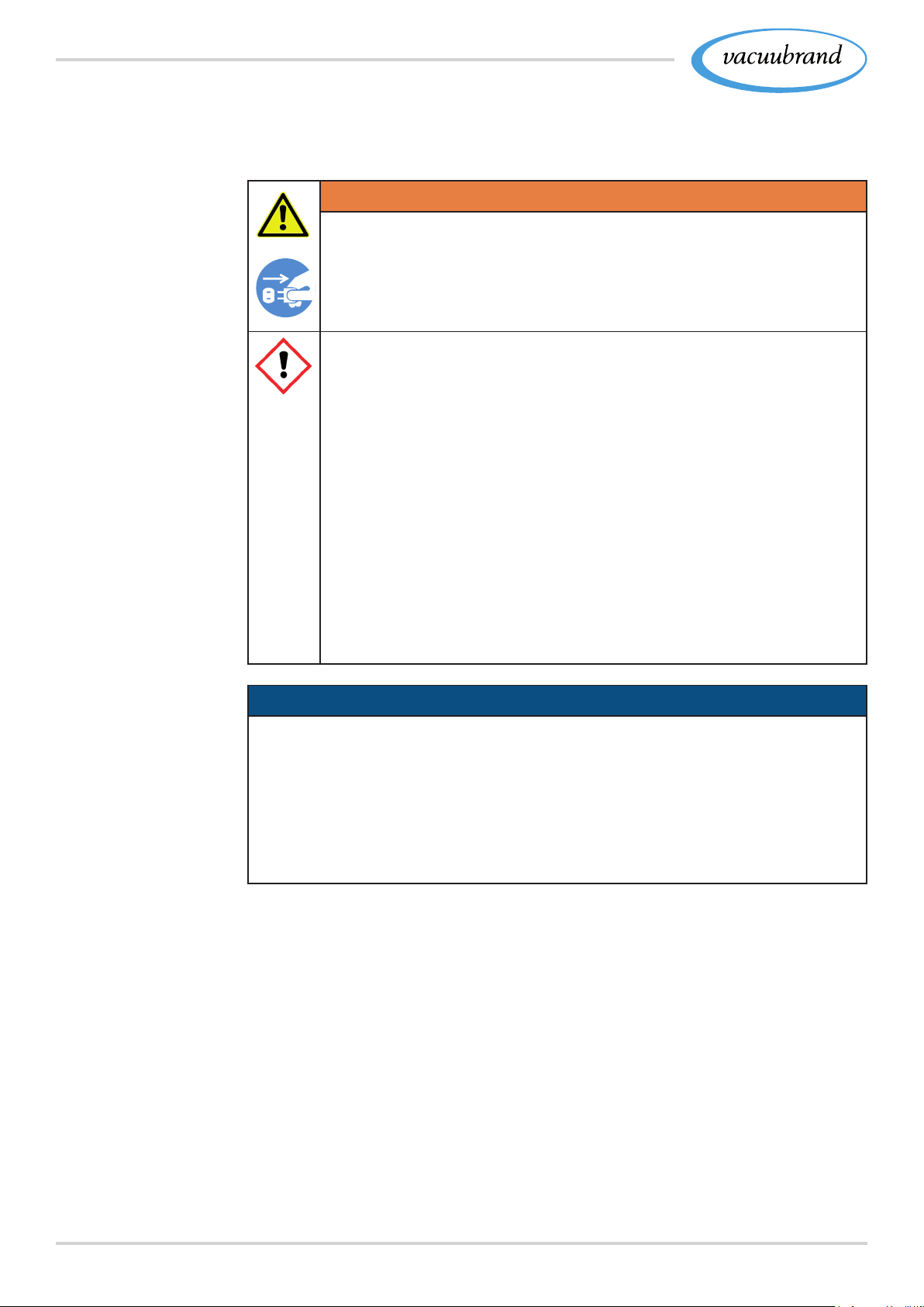
WARNING
Danger due to electrical voltage.
> Switch the device off before cleaning or performing
maintenance on the device.
> Pull out power plug.
Risk of injury because of toxic contaminated parts.
Pumping hazardous media can result in hazardous
substances adhering to parts on the inside of the
pump.
> Wear your personal protective equipment, e. g., pro‑
tective gloves, eye protection and, if necessary, re‑
spiratory protection.
> Decontaminate the vacuum pump before opening it.
If necessary, have it decontaminated by an external
service provider.
> Take safety precautions according to your directives
for handling hazardous substances.
NOTICENOTICE
Damage possible if work is performed incorrectly.
> Have maintenance work performed by a trained professional
or at least by a trained person.
> Recommendation: Please read before the rst maintenance
the complete instructions once to get an overview of the
required service activities.
54 20901367_EN_PC3001_VARIO_select_Serie_V1.2_100220
Page 55
Cleaning and maintenance
7.1 7.1 Information on service workInformation on service work
Recommended maintenance intervals
Example
Recommended aids
for cleaning and
maintenance
Maintenance intervals*Maintenance intervals*
if requiredif required 15000 h15000 h
Replace diaphragms x
Replace valves x
Clean or replace molded PTFE‑hose x
Cleaning Pumping unit x
* Recommended maintenance interval after hours of operation and under
normal operating conditions; depending on the environment and area of application, we advise performing
cleaning and maintenance as needed.
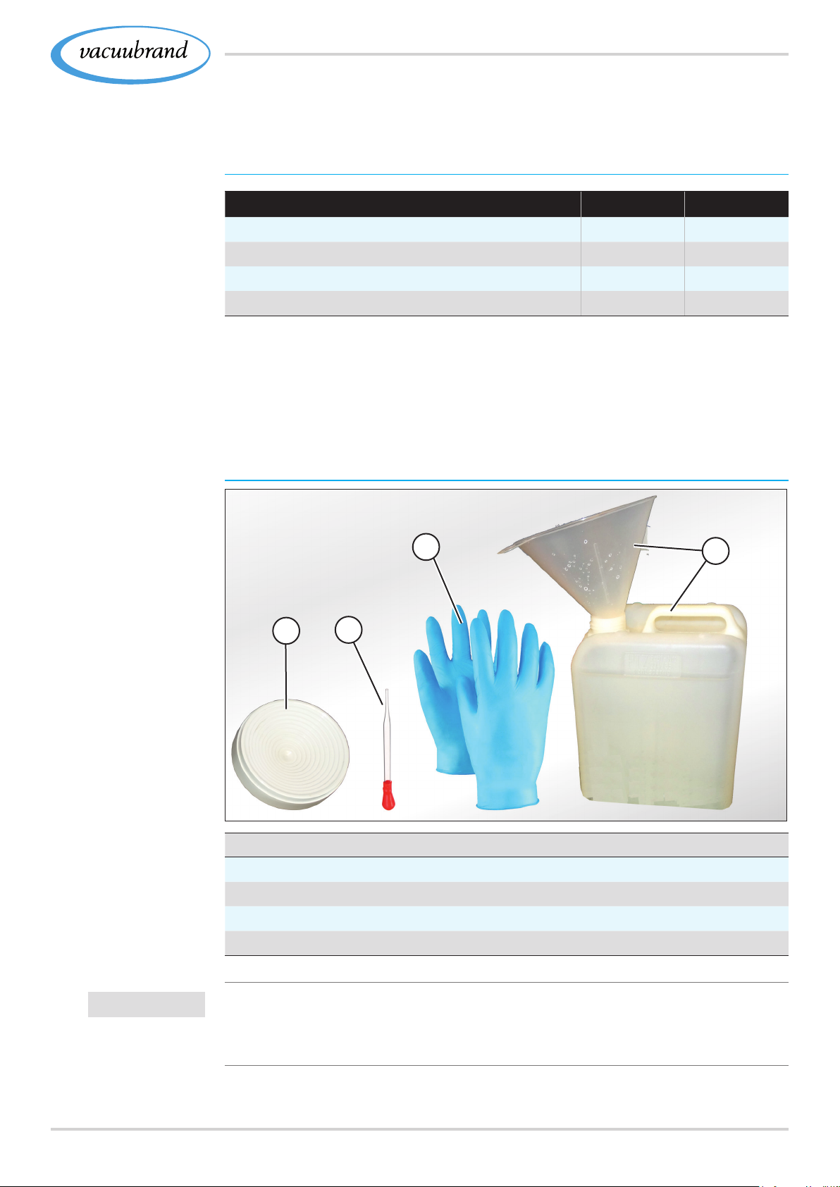
Recommended auxiliaries
3
4
IMPORTANT!
1
2
Nr Auxiliary materials
1
Round bottom ask stand
2
Glass pipette
3
Protective gloves
4
Chemically resistant vessel + funnel
> Always wear your personal protective equipment when per‑
forming activities during which you can come into contact with
hazardous substances.
5520901367_EN_PC3001_VARIO_select_Serie_V1.2_100220
Page 56
Cleaning and maintenance
Tools needed for maintenance
Example
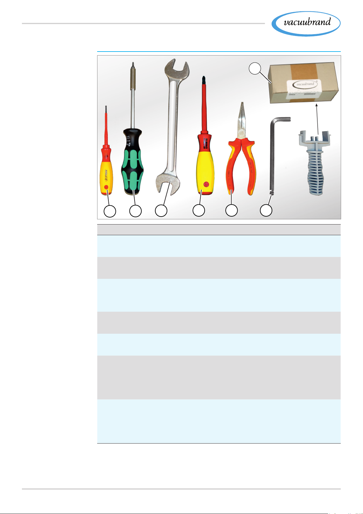
Tool
7
1
2
3
4 5
6
Nr Tool Size
1
Flat‑head screwdriver
Open hose clamps Gr. 1
2
Torx screwdriver
Screw connections counterholder EK or IK TX10
3
Fork wrench
Knurled nut M14 SW17
Rotate elbow union SW14
4
Phillips screwdriver
Screw connections holder, TE or EKP Gr. 2
5
Flat nose pliers
Close hose clamps
6
Allen key
Screw connections handle Gr. 5
Screw connections housing cover Gr. 4
Sensor fastening screws Gr. 3
7
Set of seals MD 1C #20696828
Diaphragm wrench SW46
Diaphragm
Valves
56 20901367_EN_PC3001_VARIO_select_Serie_V1.2_100220
Page 57
7.2 7.2 CleaningCleaning
Cleaning and maintenance
IMPORTANT!
Example
This chapter does not contain descriptions for the decontami‑
nation of the product. This chapter describes simple cleaning
and care measures.
> Before cleaning, switch off the Pumping unit.
7.2.1 7.2.1 Housing surfaceHousing surface
Clean surface
Clean polluted surface with a clean, slightly moistened cloth. To
moisten the cloth we recommend water or mild soap.
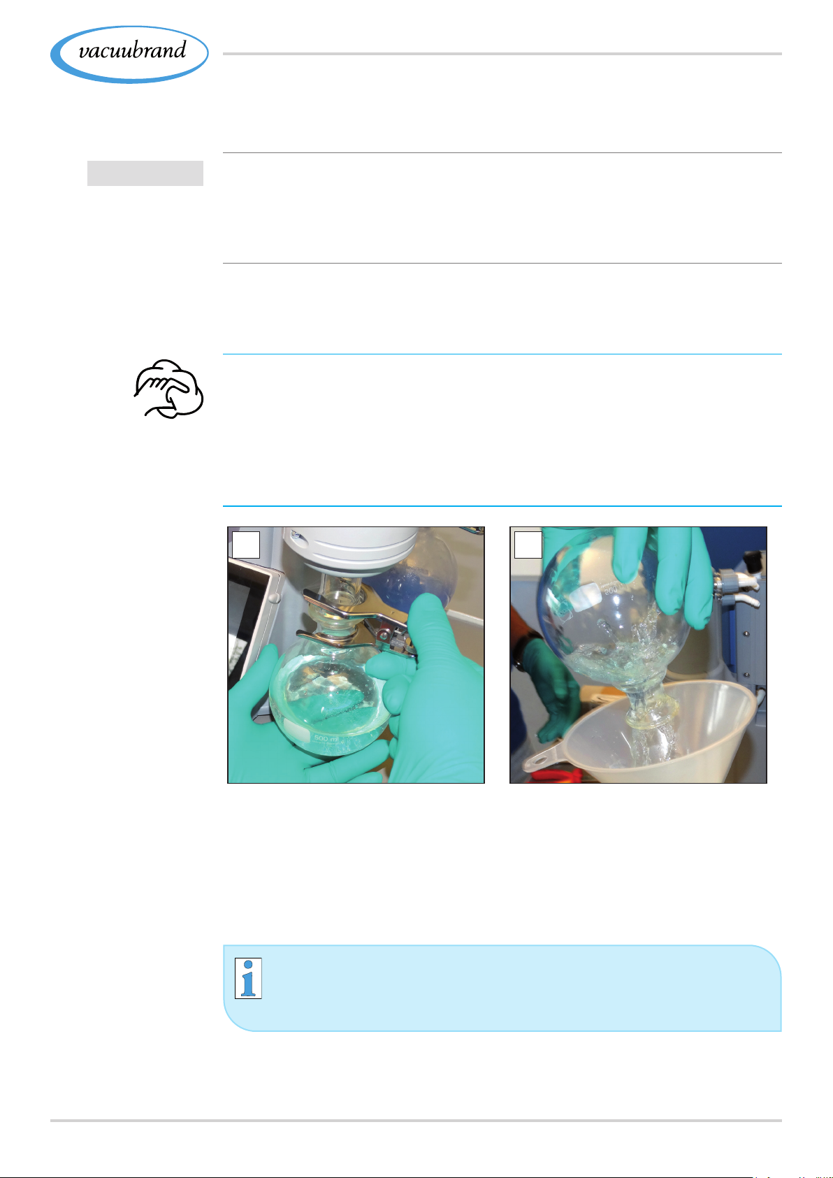
7.2.2 7.2.2 Empty glass askEmpty glass ask
Remove and empty glass ask
1
2
Empty glass ask
1. Open the joint clamp and
remove the glass ask.
3. Then x the glass ask to the condenser once again using the
joint clamp.
Depending on the application, the collected liquid can
either be reprocessed or professionally disposed of.
2. Empty the glass ask into a
suitable container, e. g., chem‑
ical‑resistant canister.
5720901367_EN_PC3001_VARIO_select_Serie_V1.2_100220
Page 58
Cleaning and maintenance
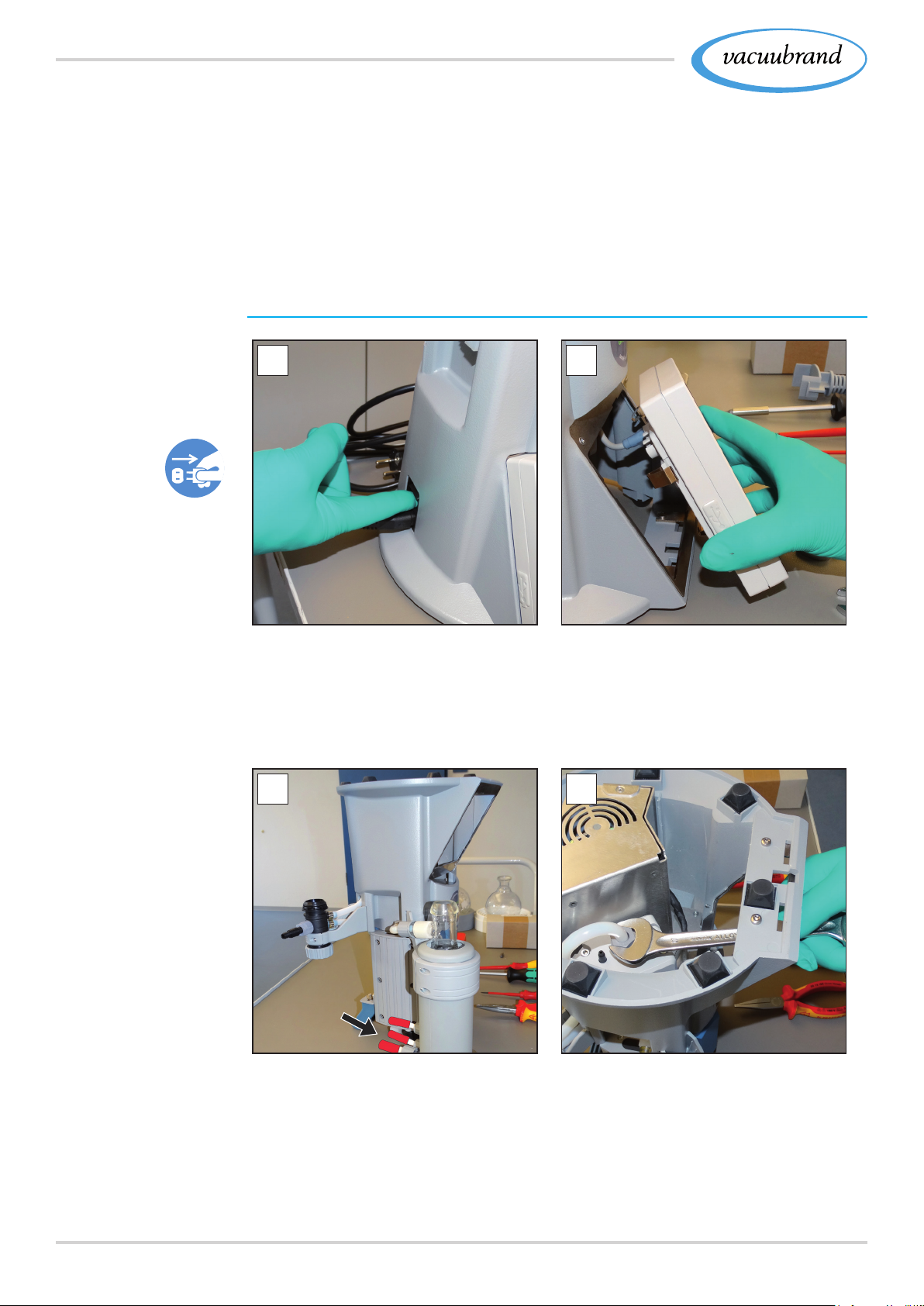
7.2.3 7.2.3 Clean sensor and venting valveClean sensor and venting valve
In the case of incorrect measurements or malfunction which sug‑
gest soiling of the sensor and/or venting valve, we recommend
cleaning the sensor and venting valve. We recommend to clean
the sensor prior to adjustment.
Remove sensor
Example
Remove sensor
1 2
1. Switch the Pumping unit off
and disconnect the power
plug.
3. Remove the glass asks and place them on a suitable ask
stand.
4 5
2. Take the vacuum controller out
of the housing and pull out the
connected VACUU·BUS plug.
4. Close the hose nozzles of the
cooler and carefully turn the
Pumping unit upside down.
58 20901367_EN_PC3001_VARIO_select_Serie_V1.2_100220
5. Open the knurled nuts on the
sensor; open‑end wrench
SW17, and remove the molded
hose.
Page 59
Cleaning and maintenance
Example
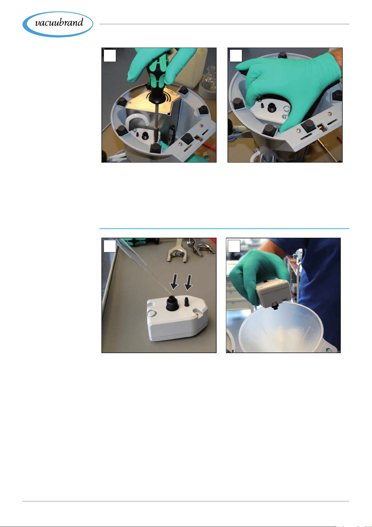
Remove sensor
6 7
6. Unscrew in the fastening
screws; Allen key size 3
Clean sensor
7. Pull out the VACUU·BUS plug
downwards and remove the
sensor.
Example Clean
measurement
chamber and venting
valve
1
1. Using a pipette, ll a small
amount of solvent, e. g., clean‑
2
2. Let the solvent react for a few
minutes before draining it.
ing solvent, into the openings.
3. Repeat this procedure until no more pollutants are in the solvent.
4. Allow the inside of the sensor air‑dry or dry under a vacuum.
5920901367_EN_PC3001_VARIO_select_Serie_V1.2_100220
Page 60
Cleaning and maintenance
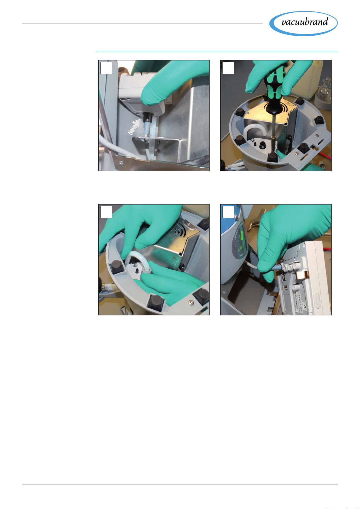
Install sensor
Example
Mount sensor
1
1. Insert the VACUU·BUS plug
and place the sensor on the
holder.
3 4
2
2. Insert the fastening screws
and screw them in hand‑tight;
Allen key Sz. 3
3. Push the molded hose onto
the connection and screw the
knurled nut on hand‑tight;
open‑end wrench SW17.
5. Secure the glass asks using the joint clamp.
6. Switch on the pumping unit and the vacuum controller.
Recommendation: Readjust the sensor if incorrect values are dis‑
played see manual of the vacuum controller .
60 20901367_EN_PC3001_VARIO_select_Serie_V1.2_100220
4. Turn the pumping unit around
to the proper position and con‑
nect the cables: VACUU·BUS,
power plug.
Page 61

Cleaning and maintenance
7.2.4 7.2.4 Clean or replace molded PTFE‑hoseClean or replace molded PTFE‑hose
Maintenance provides the opportunity to check the components
of the Pumping unit, including the tubing.
> Clean the inside of heavily polluted molded hoses, e. g., using
a pipe cleaner or the like.
> Replace brittle and defective molded hoses.
6120901367_EN_PC3001_VARIO_select_Serie_V1.2_100220
Page 62
Cleaning and maintenance
7.3 7.3 Vacuum pump maintenanceVacuum pump maintenance
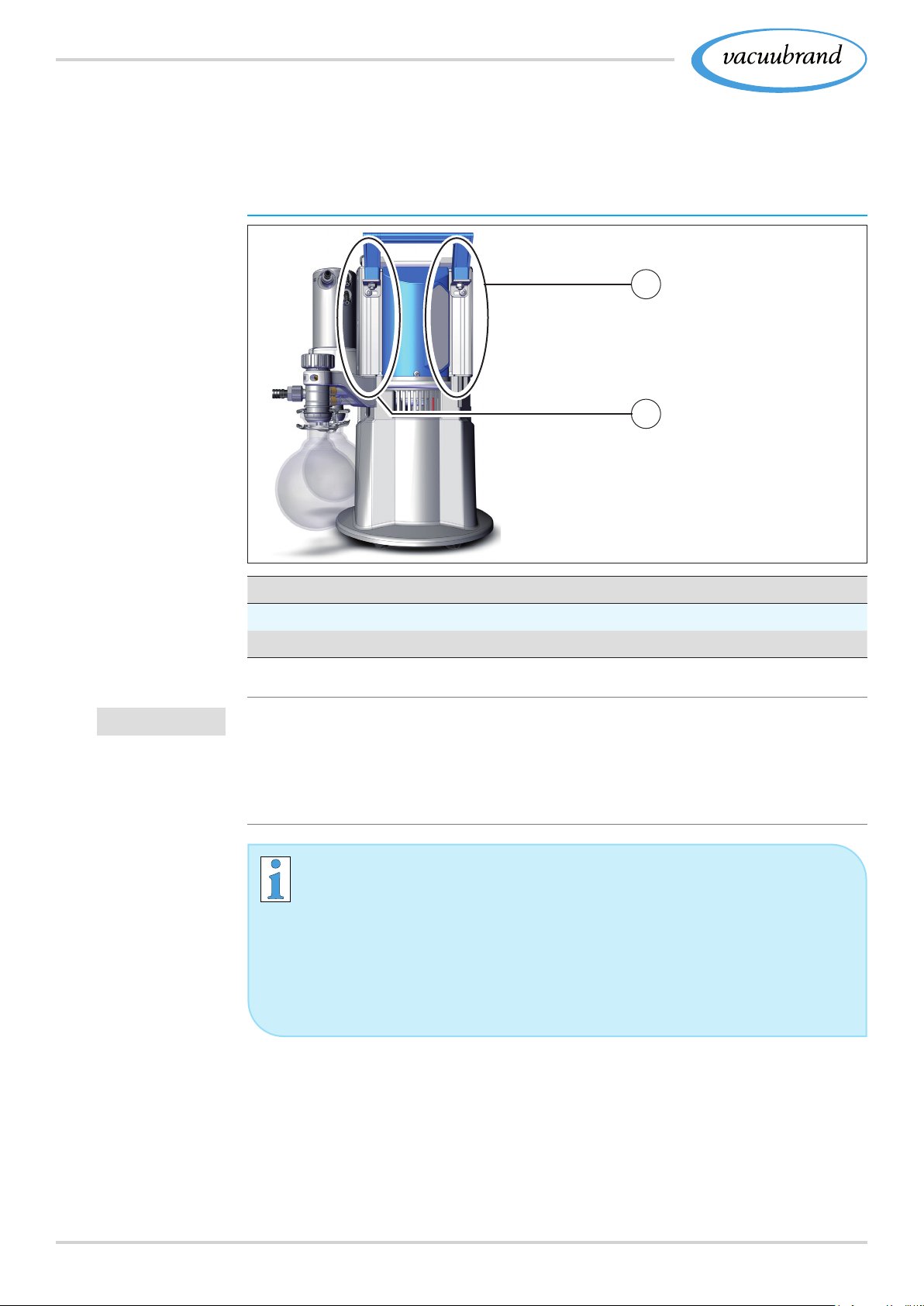
7.3.1 7.3.1 Maintenance itemsMaintenance items
Items to be maintained
Example
Maintenance of the
pump heads
1
2
IMPORTANT!
Maintenance items
1
Housing cover, power connection side
2
Housing cover with gas ballast
> Perform maintenance of the pump heads one after the other
> In the case of the pump heads, always change the dia‑
phragms and valves completely, as shown in the image
description for pump head (1).
Easy maintenance because of splitted work steps.
> First, replace the diaphragms off one pump head.
> Then change the inlet/outlet valves.
> Then perform these activities at the next pump head.
62 20901367_EN_PC3001_VARIO_select_Serie_V1.2_100220
Page 63
Cleaning and maintenance
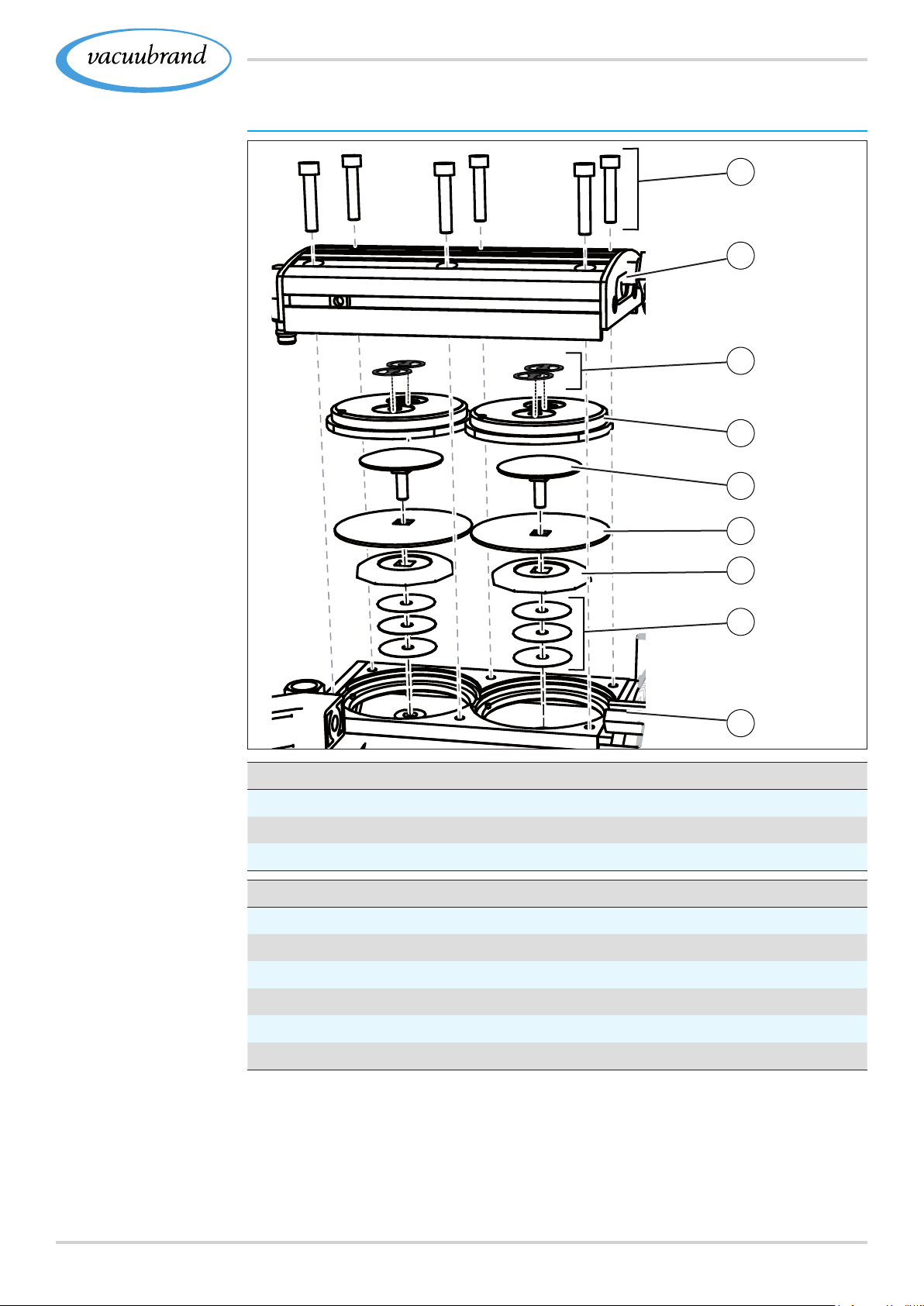
Exploded-view sketch of pump head (example)
Example
Exploded‑drawing
pump head
1
2
3
4
5
6
7
Valve maintenance
1
Screw connections
2
Housing cover
3
Valves
Diaphragm maintenance
4
Head cover
5
Diaphragm clamping disc with square‑head screw
6
Diaphragm
7
Diaphragm support disc
8
Spacer discs, max. 4 pieces
9
Pumping unit
8
9
6320901367_EN_PC3001_VARIO_select_Serie_V1.2_100220
Page 64
Cleaning and maintenance
7.3.2 7.3.2 Change diaphragms and valvesChange diaphragms and valves
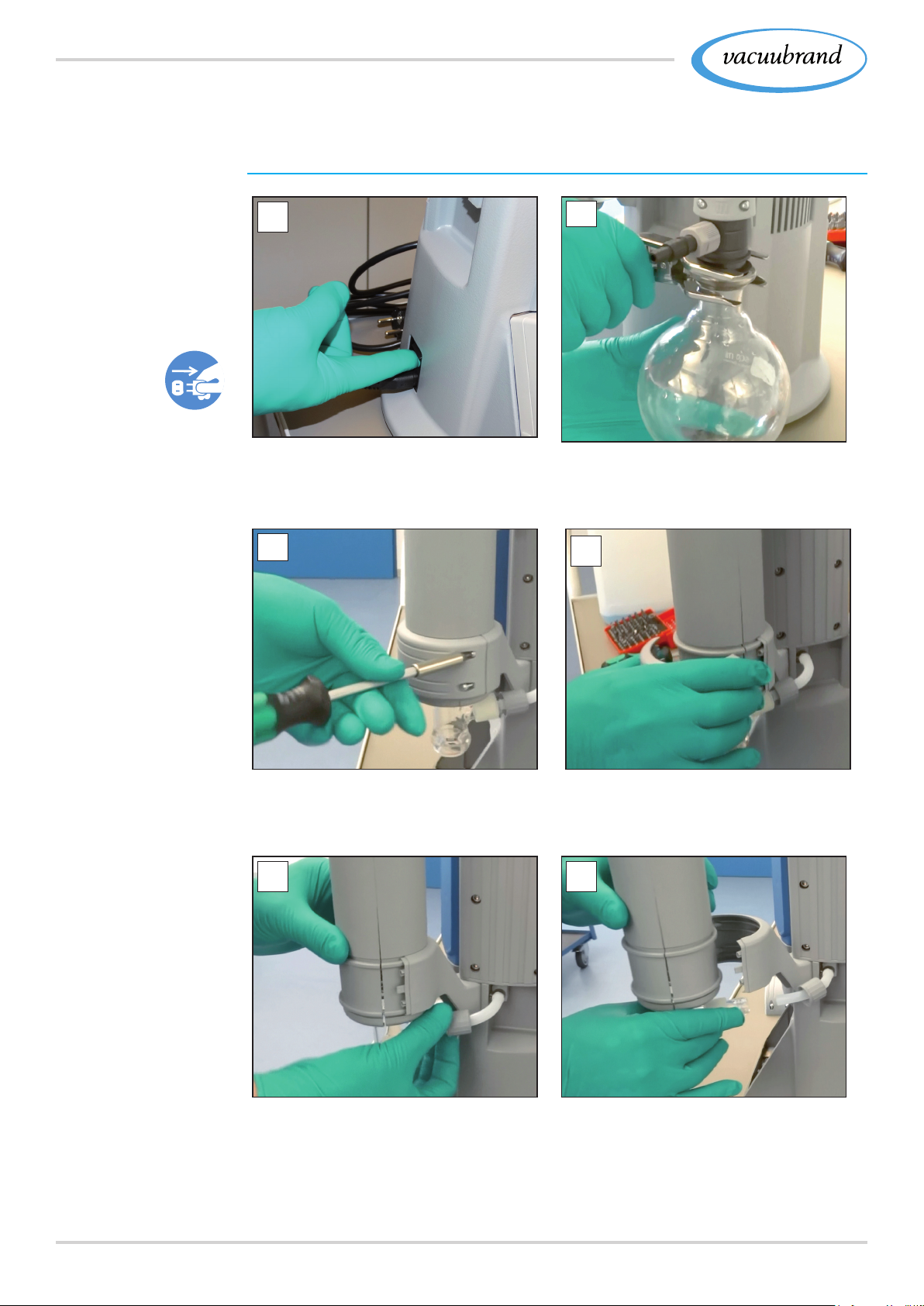
Preparation
Example
Prepare
maintenance
Example
Disassemble EK (IK)
1
1. Switch the Pumping unit off
and disconnect the power
plug.
3
2
2. Remove the glass asks as
well as connected hoses (cool‑
ant, vacuum).
4
3. Unscrew the screws from the
counterholder;
Torx screwdriver TX10
5 6
5. Screw in the nut only hand‑
tight.
4. Remove the counterholder and
lay it aside together with the
screws.
6. Remove the cooler.
64 20901367_EN_PC3001_VARIO_select_Serie_V1.2_100220
Page 65
Cleaning and maintenance
7
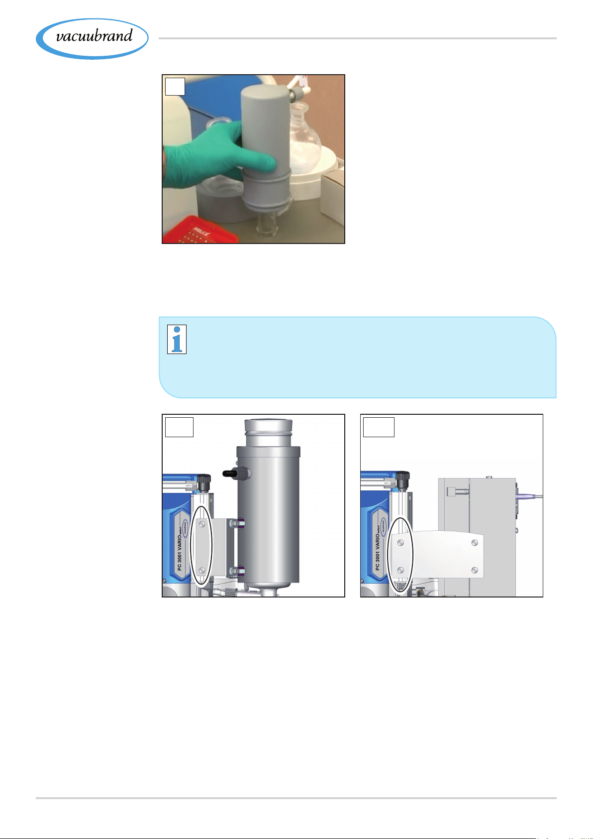
7. Set the cooler down securely
so that no liquid can escape.
Example
Disassemble TE or
EKP
The chiller TE and EKP type are xed by metal plate.
> In the case of these coolers, detach the screws of the
retaining plates on the pumping units.
TE EKP
> Unscrew the 2 fastening screws; Phillips screwdriver 2.
6520901367_EN_PC3001_VARIO_select_Serie_V1.2_100220
Page 66
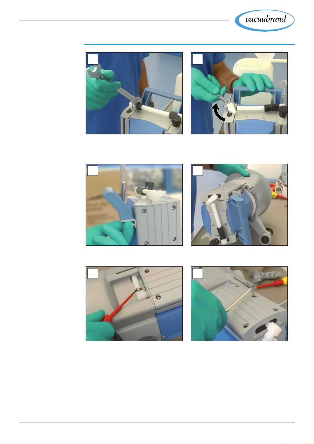
Cleaning and maintenance
Disassemble device and housing parts
Example
Disassemble
housing parts on left
1
1. Loosen the knurled nut; open‑
end wrench SW17.
3 4
2
2. Turn the elbow union a quar‑
ter turn to the side; open‑end
wrench SW14.
3. Loosen the screw connection
from the handle; Allen key 5.
5
5. Open the hose clamp; at‑
head screwdriver 1.
4. Lay the Pumping unit carefully
on its side.
6
6. Unscrew the screw connec‑
tions from the housing cover;
Allen key 4.
66 20901367_EN_PC3001_VARIO_select_Serie_V1.2_100220
Page 67
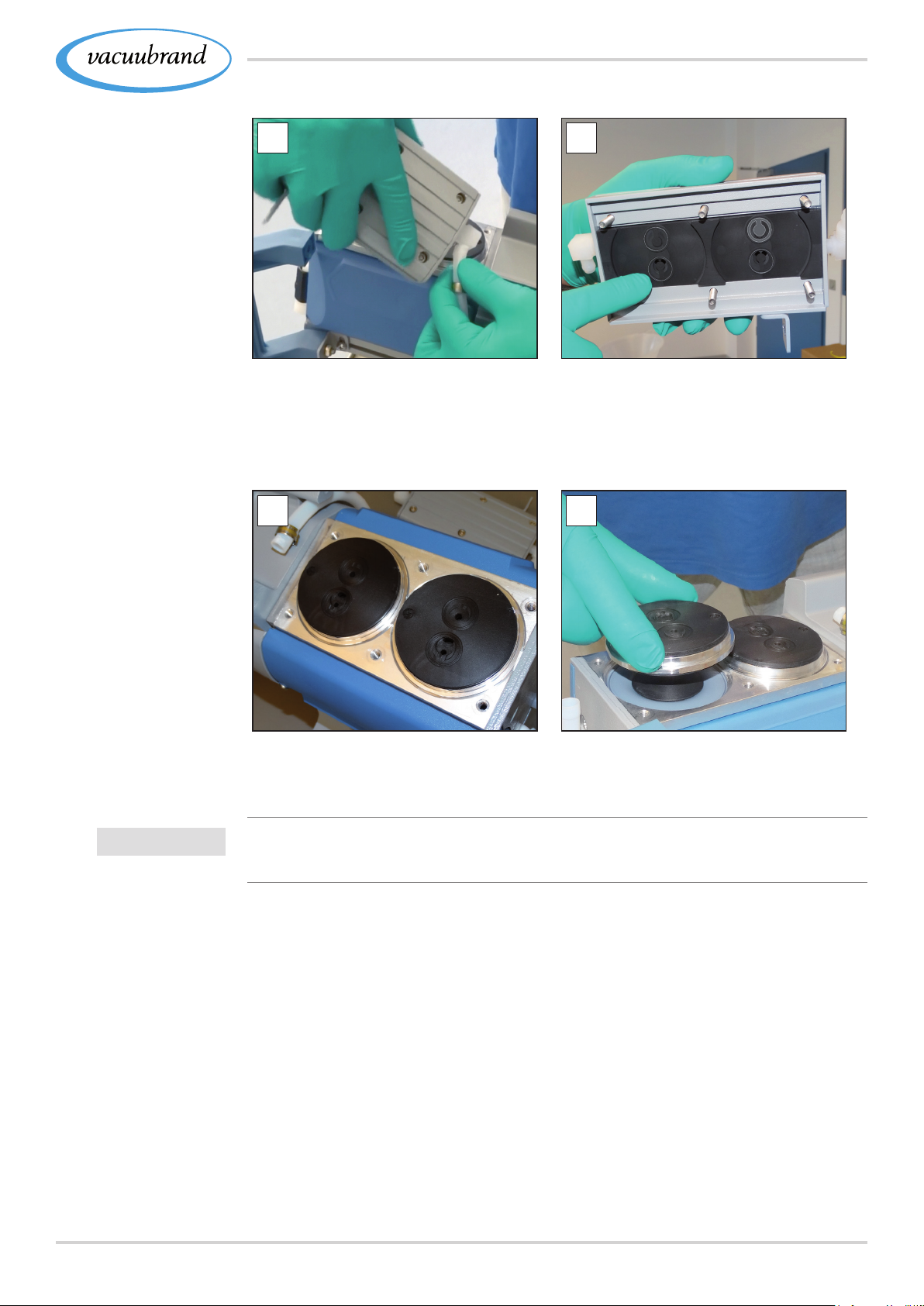
Cleaning and maintenance
Example
Disassemble
housing parts on left
9
7. Lift the housing cover and
remove the molded hose.
9
10
8. Check the housing cover for
sticking valves and place the
housing cover with the screw
connections on the side.
10
IMPORTANT!
9. Note the position of the head
covers.
Valves must be correctly positioned, otherwise the vacuum pump
will not generate any vacuum.
10. Remove the head covers.
6720901367_EN_PC3001_VARIO_select_Serie_V1.2_100220
Page 68
Cleaning and maintenance
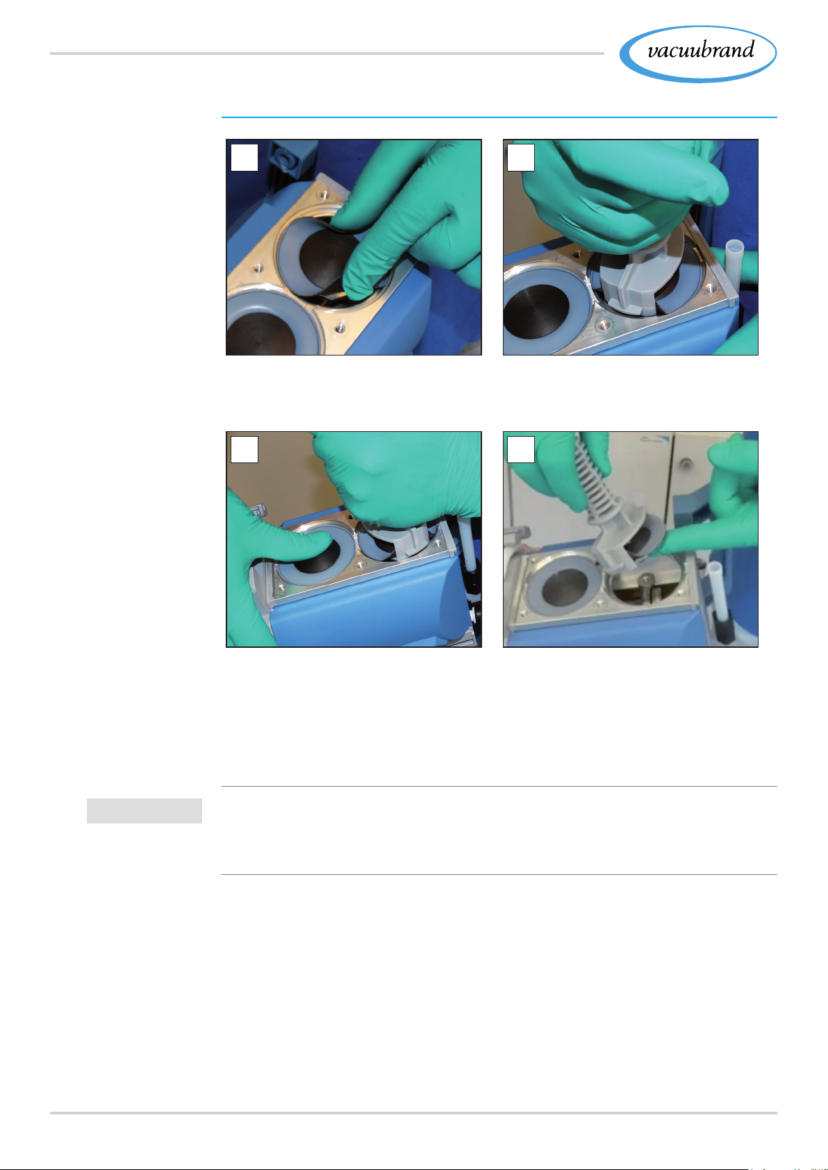
Replace diaphragm
Example
Diaphragm
replacement
1
1. Fold the diaphragm on the
sides upwards.
3 4
2
2. Carefully position the dia‑
phragm key on the diaphragm
support disc.
IMPORTANT!
3. Unscrew the assembly with the
attached diaphragm key.
4. Lift the diaphragm with all parts
out of the vacuum pump.
If spacer discs adhere to the
connecting rod, remove them
carefully.
> Never let drop spacer discs into the housing.
> Keep the spacer discs. The same number of spacer discs
must be reinserted.
68 20901367_EN_PC3001_VARIO_select_Serie_V1.2_100220
Page 69
Cleaning and maintenance
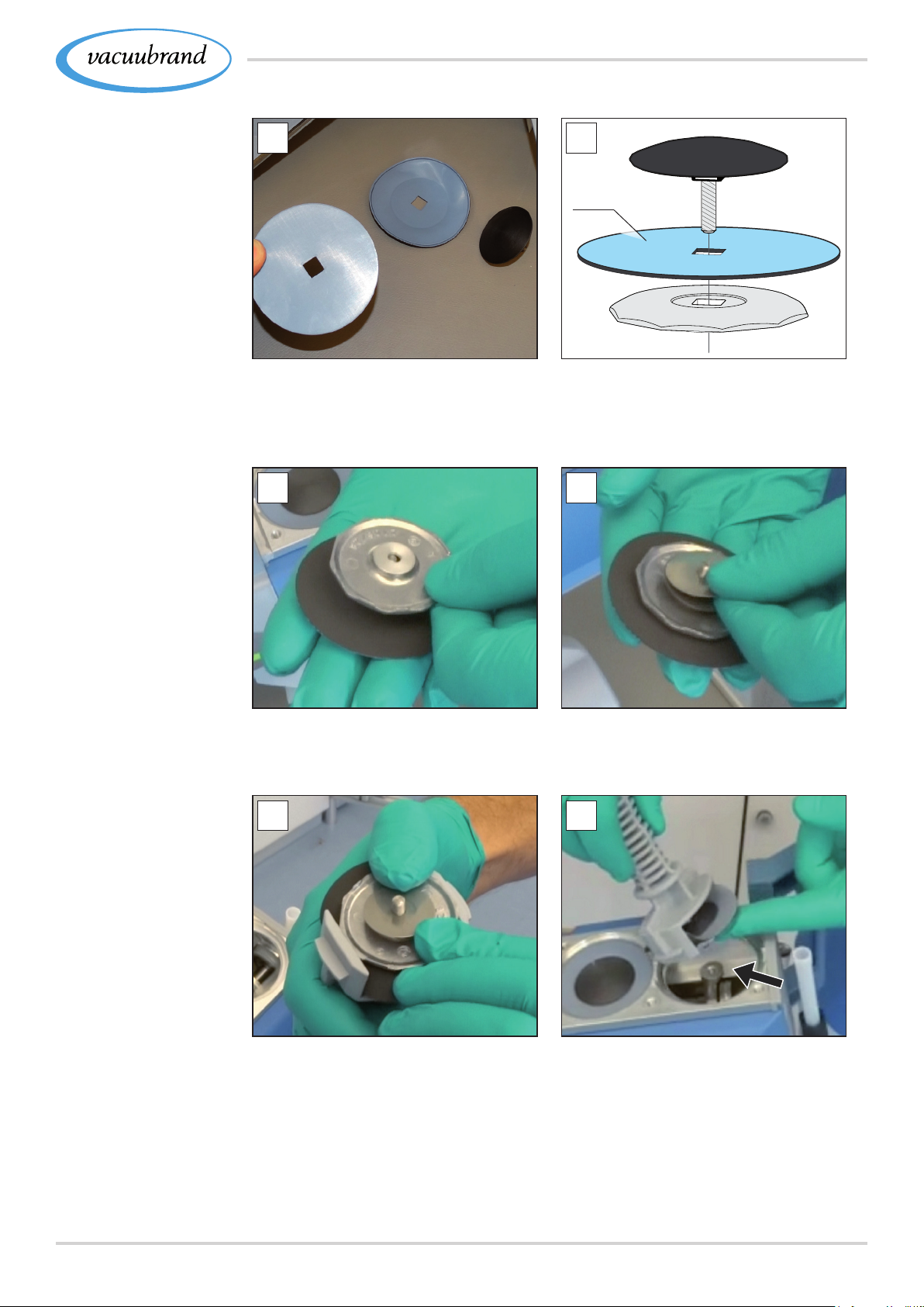
Example
Diaphragm
replacement
5
5. Disassemble the assembly
and take a new diaphragm;
seal set MD 1C.
7 8
6
TOP
6. Ensure that the diaphragm
is inserted correctly, with the
coated, light‑colored side fac‑
ing up.
7. Pay special attention to the
correct tting onto the square
of the thread.
9 10
9. Fixate the diaphragm assem‑
bly in the diaphragm key.
8. Position the correct number
spacer discs.
10. Hold the spacer discs rmly
and place the assembly on
the rod thread.
6920901367_EN_PC3001_VARIO_select_Serie_V1.2_100220
Page 70
Cleaning and maintenance
Example
Diaphragm
replacement
Example
Valve replacement
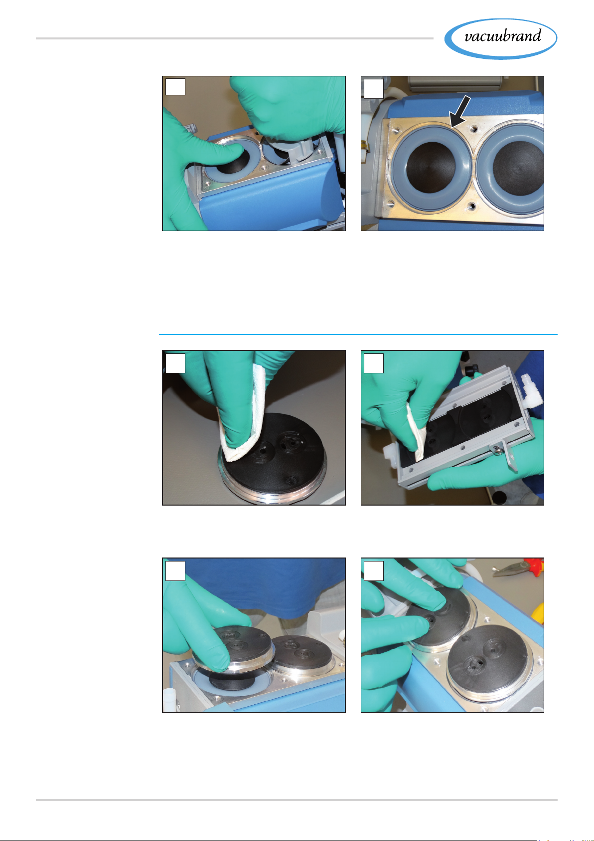
11
11. Tighten the assembly hand‑
tight using the diaphragm
key.
Change valves
1
12
12. Repeat the process for the
second diaphragm.
2
1. Clean dirty head covers and 2. housing cover carefully using a
cloth.
3 4
3. Place both head covers in the
correct position.
4. Position the new valves and
align them; sealing set MD 1C.
70 20901367_EN_PC3001_VARIO_select_Serie_V1.2_100220
Page 71
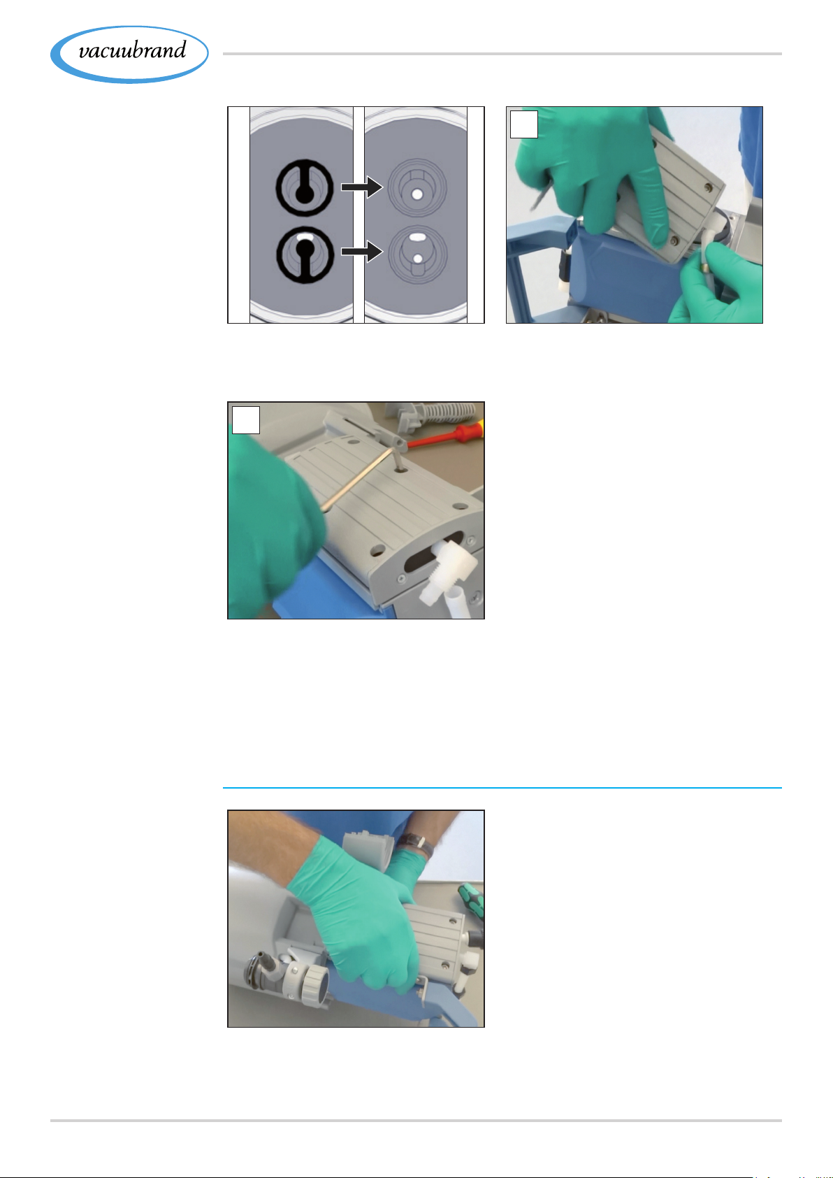
Cleaning and maintenance
Example
Valve replacement
Top view cutout: Proper position‑
ing of the valves.
6
5
5. If all valves are correctly posi‑
tioned, rst insert the molded
hose.
Example
Maintenance of the
second pump head
6. Place the housing cover as
well and screw in the screw
connections; Allen key 4, tight‑
ening torque, 6 Nm.
Changing the diaphragm and valve of the next pump head
> Turn the pumping unit to the
other side.
> Repeat the steps from the
previous descriptions for
changing the diaphragm and
valve.
7120901367_EN_PC3001_VARIO_select_Serie_V1.2_100220
Page 72
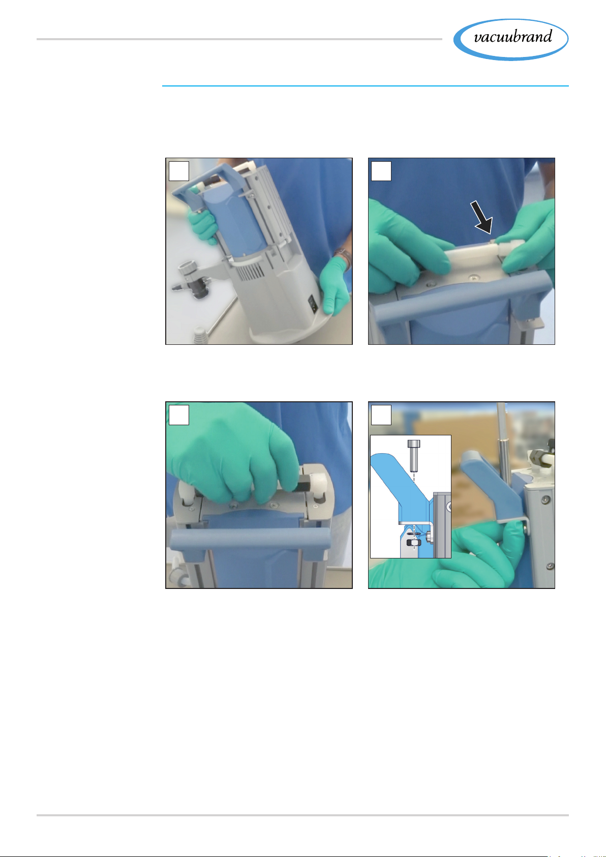
Cleaning and maintenance
Assemble device and housing parts
Before putting the pumping unit back into service, all device and
housing parts which had been previously removed must rst be
xed once again.
Example
Assemble device
and housing parts
1 2
1. Position the pumping unit. 2. Turn the elbow union a quar‑
ter turn back into the molded
hose.
3
4
3. Tighten the knurled nut hand‑
tight; fork wrench SW17.
72 20901367_EN_PC3001_VARIO_select_Serie_V1.2_100220
4. Fix the handle; Allen key 5.
Page 73
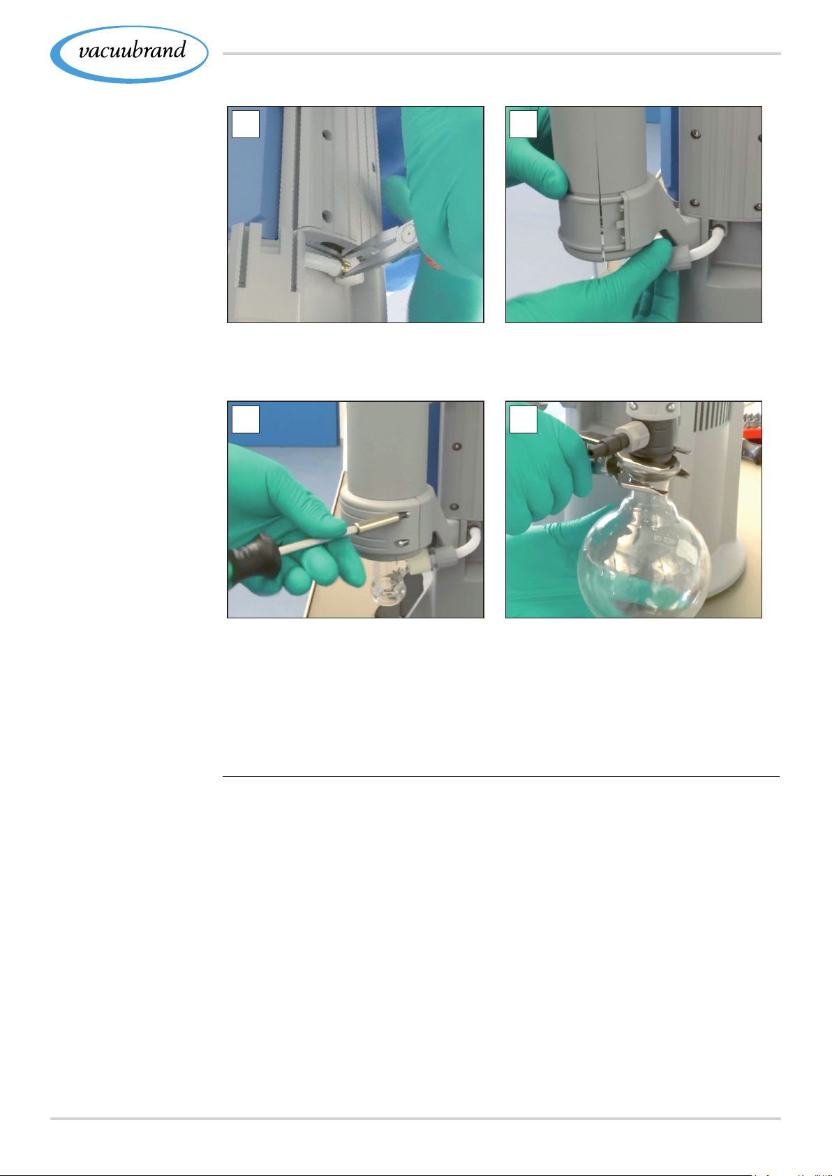
Cleaning and maintenance
5
5. Close the open hose clamps
using the at nose pliers.
7
6
6. Attach the molded hose and
tighten the knurled nut hand‑
tight.
8
7. Secure the counterholder;
Torx screwdriver TX10.
For EKP or TE, screw on the
retaining plate; Phillips screw‑
driver 2.
8. Fasten the glass asks using
the joint clamp.
If the maintenance work is completed in full:
> Connect the hose system for operation.
> Connect the pumping unit to the power supply.
5 Pumping unit ready to return to service.
Without reconnection:
5 Pumping unit prepared for storage.
7320901367_EN_PC3001_VARIO_select_Serie_V1.2_100220
Page 74

Appendix
8 8 AppendixAppendix
8.1 8.1 Technical informationTechnical information
Chemistry pumping units
PC 3001 VARIO select PC 3001 VARIO select IK
PC 3001 VARIO select TE PC 3001 VARIO select EKP
8.1.1 8.1.1 Technical dataTechnical data
Technical data
Ambient conditions
Ambient temperature, max. 10–40 °C 50–104°F
Altitude, max.
Relative humidity 30–85 %, nicht betauend
Pollution degree 2
Impact energie 5 J
Protection type (IEC 60529) IP 20
Protection type (UL 50E) NEMA Type 1
Prevent condensation or contamination from dust, liquids, or corrosive
gases.
2000 m
above sea level
Operating conditions
Operating temperature 10–40 °C 50–104°F
Transport and storage tempera‑
ture
Maximum admissible media temperature (gas), non‑explosive atmo‑
sphere:
momentarily 80 °C 176°F
Continuous operation 45 °C 113°F
ATEX conformity II 3/‑ G IIC T3 X Internal Atm. only
‑10–60 °C 14–140°F
(US)
6562 ft
above sea level
(US)
Maximum admissible media temperature (gas)
momentarily 40 °C 104°F
Continuous operation 40 °C 104°F
` atmosphere:
Connections
Vacuum inlet IN
Gas ballast Gas ballast valve, manual
Inert gas adapter – OPTION Small ange GB NT KF DN 16
Venting valve (venting with in‑
ert gas) – OPTION
74 20901367_EN_PC3001_VARIO_select_Serie_V1.2_100220
Hose nozzle DN 6/10
Hose nozzle GB NT DN 6/10
Silicone rubber hose 3/6
Page 75

Appendix
Technical data
Coolant water EK (+IK)
Exhaust gas, outlet EX
2x (+2x ) Hose nozzle DN 6/8
Hose nozzle DN 8/10
Cold‑device plug + Power supply CEE, CH, CN, UK, IN, US
Plug‑in connector VACUU·BUS
®
Electrical data
Nominal voltage 100‑230 VAC ±10 %
Frequency 50/60 Hz
Power Surge Category
Nominal current at 50 Hz 1,6‑0,7 A
Capacity, max. 0,16 kW
Interface VACUU·BUS
Power cable 2 m
Vacuum data
Max. Pumping speed 2,0 m
Ultimate vacuum, abs. 2,0 mbar 1.5 Torr
Ultimate vacuum with GB, abs. 4 mbar 3 Torr
Max. Inlet pressure, abs. 1,1 bar 825 Torr
II
®
(US)
3
/h 1.18 cfm
Max. Outlet pressure, abs. 1,1 bar 825 Torr
Max. Differential pressure, abs. 1,1 bar 825 Torr
Max. Max. pressure at gas con‑
nections, abs.
1,2 bar 900 Torr
Number of cylinders/stages 4/3 4/3
Sensor integriert integrated
Measuring principle Ceramic diaphragm (aluminum oxide),
capacitive, gas type independent, abso‑
lute pressure
Accuracy of measurement ±1 mbar/hPa/Torr, ±1 digit
(after adjustment, constant temperature)
Upper measurement limit 1080 mbar 810 Torr
Lower measurement limit 0,1 mbar 0.1 Torr
Temperature coefcient < 0,15 mbar/hPa 0.11 Torr/K
Weights* and dimensions (l x b x h)
PC 3001 VARIO select
303 mm x 306 mm
x 400 mm
11.93 in x 15.75 in
(US)
12.05 in x
Weight* 8,2 kg 18.08 lb
PC 3001 VARIO select TE 300 mm x 341 mm
x 493 mm
11.81 in x 13.43 in
x 19.41 in
Weight* 8,7 kg 19.18 lb
PC 3001 VARIO select IK 309 mm x 312 mm
x 400 mm
12.17 in x 12.28 in
x 15.75 in
Weight* 8,8 kg 19.4 lb
7520901367_EN_PC3001_VARIO_select_Serie_V1.2_100220
Page 76

Appendix
Wetted materials
PC 3001 VARIO select EKP 300 mm x 370 mm
x 400 mm
Weight* 11,8 kg 26.01 lb
* without cable
11.81 in x 14.57 in
x 15.75 in
Other data
Sensor type
Controller
VACUU·SELECT Sensor
VACUU·SELECT
Volume of separator (glass ask) á 500 ml
Sound pressure level at 1500 rpm/62%
(VARIO)
42 dBA
8.1.2 8.1.2 Wetted materialsWetted materials
Component Wetted materials
Pump
Housing cover PTFE
Head cover ETFE, carbon‑ber‑reinforced
Diaphragm clamping disc ETFE, carbon‑ber‑reinforced
Diaphragm PTFE
Valves FFPM
Pumping unit
Inlet PPS (IK: PP)
Outlet PET (PC 3001 without EK:
PTFE carbon‑ber‑reinforced)
Hoses PTFE
Hose ttings ETFE, ECTFE
O‑ring on separator Fluoroelastomer
Overpressure valve on vapor
Silicone rubber, PTFE lm
condenser
Distributor head (inlet) PPS, glass‑ber‑reinforced, PP
(blind plate)
Condenser IK, EK, TE Borosilicate glass
Round bottom ask Borosilicate glass
Emission condenser Peltronic ETFE, ECTFE, PP, PA
Silencer PBT, PVF, rubber
VACUU·SELECT Sensor
Vacuum sensor Aluminium oxide ceramics, gold‑
coated
Measurement chamber PPS
Small ange PP
Sealing ring at the sensor chemically resistant uorelastomer
Hose nozzle PP
Seal on the venting valve FFPM
76 20901367_EN_PC3001_VARIO_select_Serie_V1.2_100220
Page 77
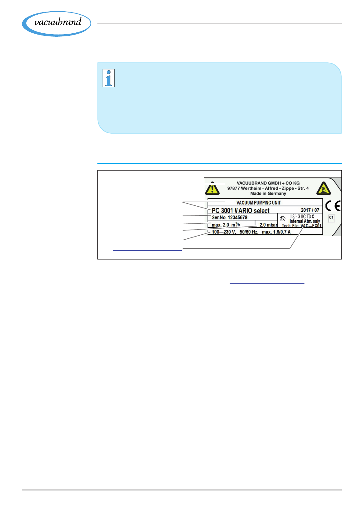
8.1.3 8.1.3 Rating plateRating plate
Appendix
Data on rating plate
Example
Detail Rating plate
> In the event of an error, make a note of the type and serial
number on the rating plate.
> When contacting our Service Department, please provide
the type and serial number from the rating plate. This will
allow us to provide you with specic support and advice for
your device.
Pating plate pumping unit, in general
Manufacturer
Type/Year of con‑
truction/Month
Serial number
Pumping speed
Ultimate vacuum
Power supply
ATEX specication*
* Documentation, group and category, marking G (gas), type protection,
explosion group, temperature class (additionally see : Approval for ATEX equipment).
7720901367_EN_PC3001_VARIO_select_Serie_V1.2_100220
Page 78

Appendix
8.2 8.2 Ordering informationOrdering information
Ordering information
pumping unit
Ordering information
accessories
Ordering information
spare parts
Chemistry pumping units
PC 3001 VARIO select CEE 20700200
CH 20700201
UK 20700202
US 20700203
CN 20700206
IN 20700207
Accessories
Vacuum hose DN 6 mm (l = 1000 mm) 20686000
Vacuum hose DN 8 mm (l = 1000 mm) 20686001
Coolant valve VKW‑B 20674220
Venting valve (air admittance valve) VBM‑B 20674217
Level sensor 20699908
VACUU·SELECT Sensor 20612881
VSK 3000 20640530
DAkkS calibration with rst delivery 20900214
DAkkS recalibration 20900215
Spare parts
Hose nozzle 6 rounded 20639948
Hose nozzle DN 6/10 20636635
Small ange KF DN 16 20635008
Extension cable VACUU·BUS, 0.5 m 20612875
Extension cable VACUU·BUS, 2 m 20612552
Extension cable VACUU·BUS, 10 m 22618493
Joint clip VA KS35/25 20637627
Glass ask/round bottom ask 500 ml 20638497
Knurled nut M14x1 (union nut) 20637657
PA Locking ring for knurled nut 20637658
Dry ice condenser TE
Immission condenser IK 20636256
®
Peltronic
Anti‑rotation protection D17x17.5 20635113
emission condenser EKP 20636298
Order no.
Order no.
Order no.
on request
Gas ballast cap 20639223
Power cable CEE 20612058
CH 20676021
CN 20635997
IN 20635365
UK 20612065
78 20901367_EN_PC3001_VARIO_select_Serie_V1.2_100220
Page 79
> A full list of available spare parts is available under
VACUUBRAND > Support > Repair instructions > Chemistry
pumping units.
Sources of supply
Appendix
International
sales ofces and
distribution
Purchase original accessories and original spare parts from a
subsidiary of VACUUBRAND GMBH + CO KG or your local dis‑
tributor.
> Information about our complete product range is available
in the current product catalog.
> Your local distributor or VACUUBRAND GMBH + CO KG
sales ofce is available to assist you with orders, questions
on vacuum control and optimal accessories.
7920901367_EN_PC3001_VARIO_select_Serie_V1.2_100220
Page 80
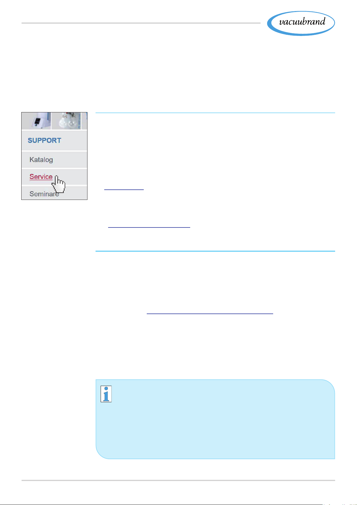
Appendix
8.3 8.3 ServiceService
Service offer and
service range
Take advantage of the comprehensive range of services avail‑
able from
VACUUBRAND GMBH + CO KG.
Services in detail
Product consultation and practical solutions
Fast delivery of spare parts and accessories
Professional maintenance
Immediate repairs processing
On‑site service (on request)
Calibration (DAkkS‑accredited)
With Health and Safety Clearance form: return, disposal.
> Visit our website for further information:
www.vacuubrand.com.
Meet the
terms of service
Return (reshipment)
Service handling
1. Contact your local distributor or our Service Department.
2. Request an RMA no. for your order.
3. Clean the product thoroughly or if necessary, decontaminate
it professionally.
4. Fill out the Health and Safety Clearance form in full.
5. Return your product, including:
RMA no.
Repair or service order
Health and Safety Clearance form
Error description.
> Reduce downtime, speed up processing. Please have the
required data and documents at hand when contacting our
Service Department.
` Your order can be quickly and easily processed.
` Hazards can be prevented.
` A brief description and/or photos will help locate the
source of the error.
80 20901367_EN_PC3001_VARIO_select_Serie_V1.2_100220
Page 81

8.4 8.4 IndexIndex
Appendix
Index
A
Abbreviations ................ 9, 10
Accessories .................. 78
Action step ..................... 9
Additional symbols ............... 8
Assemble device and housing parts 72
ATEX equipment category ........ 22
ATEX equipment labeling ........ 22
C
Clean measurement chamber and
venting valve . . . . . . . . . . . . . . . . . . 59
Clean surface ................. 57
Connect pumping unit electrically .. 42
Connect venting valve ........... 40
Coolant connection ............. 35
Cooling with dry ice condenser . . . . 36
Copyright © .................... 5
D
Deadlock protection ............. 21
Diaphragm replacement ......... 68
Disassemble device and housing parts
66
Disassemble EK (IK) ............ 64
Disassemble housing parts on left .. 66
Disassemble TE or EKP ......... 65
Display conventions .............. 7
Display of action steps ............ 9
Distributors ................... 79
Dry ice condenser (dry ice cooler) .. 10
E
EC Declaration of Conformity ..... 83
Electrical connection . . . . . . . . . . . . 42
Eliminate sources of danger ...... 18
Empty glass ask ............... 57
Entsorgung ................... 23
Error – Cause – Remedy ......... 50
Exhaust gas connection ......... 34
Explanation of safety symbols ...... 8
Exploded‑drawing pump head ..... 63
F
Fill TE with freezing mixture ...... 37
Foreseeable misuse ............ 13
G
Goods arrival .................. 30
H
Handling instruction .............. 9
Health and Safety Clearance form . 80
hot surface .................... 20
I
Icons ......................... 8
Improper use .................. 13
Incorrect measurements ......... 18
Incorrect measurements
avoid ........................ 19
Instruction modules .............. 6
Intended use .................. 12
L
limitations of use ............... 32
M
Maintain minimum distance ....... 20
Maintenance of the pump heads ... 62
Maintenance of the second pump head
71
Mandatory sign ................. 8
Measurement chamber . . . . . . . . . . 76
Minimum distances ............. 31
Mount sensor .................. 60
O
Operate gas ballast valve ........ 47
Operating elements
Vacuum controller .............. 45
Operating hours maintenance ..... 55
Operating panel ................ 11
Operation with gas ballast ........ 47
Operator obligations ............ 14
Ordering information ............ 78
Ordering information pumping unit se‑
ries .......................... 78
Overheating ................... 20
Overheating protection .......... 21
Overview
Chemistry pumping units ......... 25
P
Peripheral devices and ATEX ..... 22
Permissible chill temperatures ..... 36
Personnel obligations ........... 14
Personnel qualication .......... 15
Power cable ................... 42
Prepare maintenance ........... 64
Prevent blocked exhaust gas line .. 18
Prevent condensate reow ....... 18
Prevent ignition source .......... 22
Process screen (main screen) ..... 45
Product‑specic abbreviations ..... 25
Product‑specic terms ........ 10, 11
Prohibition sign ................. 8
Proper disposal . . . . . . . . . . . . . . . . 23
Protective clothing .............. 16
Q
Qualication description ......... 15
Quality commitment ............. 16
R
Rating plate ................... 77
Remove sensor ............. 58, 59
Reset overheat protection ........ 51
Residual energies .............. 19
Responsibility Assignment Matrix .. 15
Responsibility matrix and areas of com‑
petence ...................... 15
8120901367_EN_PC3001_VARIO_select_Serie_V1.2_100220
Page 82

Appendix
Index
Return (reshipment) ............. 80
Return to service after maintenance 73
Risks of
Venting ....................... 19
Risks with cryogenic substances ... 21
Rotary evaporation ............. 29
S
Safety information . . . . . . . . . . . . . . 12
Safety Information for Vacuum Equip‑
ment ......................... 12
Safety precautions .............. 16
Sensor position ............. 39, 40
Service handling ............... 80
Service range ................. 80
Sources of supply .............. 79
Spare parts ................... 78
Specications
Coolant mixtures . . . . . . . . . . . . . . . 36
Start ......................... 46
Stop ......................... 46
Storage, preparation ............ 73
Structure of the Operating instructions
6
Switch‑off pumping unit .......... 48
Switch on pumping unit .......... 44
Symbols ....................... 8
T
Target groups .................. 15
Technical data . . . . . . . . . . . . . . 74, 75
Technical information ............ 74
U
Unpacking . . . . . . . . . . . . . . . . . . . . 30
User information ................ 5
V
VACUU·BUS® ................. 10
VACUU·BUS® connector ..... 10, 11
Vacuum concentrator ............ 29
Vacuum connection ............. 33
Vacuum controller operation ...... 44
Valve replacement .............. 70
Valves, pump head ............. 63
Venting ....................... 46
W
Warning sign ................... 8
Warning signs and labels ........ 21
Wetted materials ............... 76
82 20901367_EN_PC3001_VARIO_select_Serie_V1.2_100220
Page 83
Appendix
8.5 8.5 EC Declaration of ConformityEC Declaration of Conformity
EU-Konformitätserklärung
EC Declaration of Conformity
Déclaration CE de conformité
Hersteller / Manufacturer / Fabricant:
VACUUBRAND GMBH + CO KG · Alfred‑Zippe‑Str. 4 · 97877 Wertheim · Germany
Hiermit erklärt der Hersteller, dass das Gerät konform ist mit den Bestimmungen
der Richtlinien:
Hereby the manufacturer declares that the device is in conformity with the
directives:
Par la présente, le fabricant déclare, que le dispositif est conforme aux directives:
2006/42/EG (M‑RL), 2014/30/EU (EMV‑RL), 2014/34/EU (ATEX‑RL),
2011/65/EU, 2015/863 (RoHS‑2)
Chemie‑Pumpstand‑Serie / Chemistry pumping unit series / Groupe de pompage
Typ / Type / Type: PC 3001 VARIO select, PC 3001 TE VARIO select,
PC 3001 EKP VARIO select, PC 3001 IK VARIO select
Artikelnummer / Order number / Numéro d‘article: 20700205, 20700225, 20700245,
20700265
Seriennummer / Serial number / Numéro de série: Siehe Typenschild / See rating
plate / Voir plaque signalétique
Angewandte harmonisierte Normen / Harmonized standards applied / Normes har‑
monisées utilisées: DIN EN ISO 12100:2011, DIN EN 1012‑2:2011, IEC 61010‑
1:2010 (Ed. 3), DIN EN 61010‑1:2011, DIN EN 61326‑1:2013, DIN EN 1127‑1:2011,
DIN EN ISO 80079‑36:2016, DIN EN IEC 63000:2019
Bevollmächtigter für die Zusammenstellung der technischen Unterlagen / Person
authorised to compile the technical le / Personne autorisée à constituer le dossier
technique: Dr. F. Gitmans · VACUUBRAND GMBH + CO KG · Germany
Ort, Datum / place, date / lieu, date: Wertheim, 10.02.2020
chimiechimie
i. A.
(Dr. F. Gitmans) (Dr. A. Wollschläger)
Geschäftsführer / Managing Director /
Gérant
VACUUBRAND GMBH + CO KG
Alfred‑Zippe‑Str. 4
97877 Wertheim
Regulatory Affairs Manager / Directrice
des affaires réglementaires
8320901367_EN_PC3001_VARIO_select_Serie_V1.2_100220
Page 84

84 20901367_EN_PC3001_VARIO_select_Serie_V1.2_100220
Page 85

8520901367_EN_PC3001_VARIO_select_Serie_V1.2_100220
Page 86

86 20901367_EN_PC3001_VARIO_select_Serie_V1.2_100220
Page 87

8720901367_EN_PC3001_VARIO_select_Serie_V1.2_100220
Page 88

Technology for Vacuum Systems
Manufacturer:
VACUUBRAND GMBH + CO KG
Alfred‑Zippe‑Str. 4
97877 Wertheim
GERMANY
Phone:
Head ofce +49 9342 808‑0
Sales +49 9342 808‑5550
Service +49 9342 808‑5660
Version: 20901367_EN_PC3001_VARIO_select_Serie_V1.2_100220 – TDD2 – © VACUUBRAND GMBH + CO KG – 2020
 Loading...