

Page 1
page 1 of 49
Technology for Vacuum Systems
Instructions for use
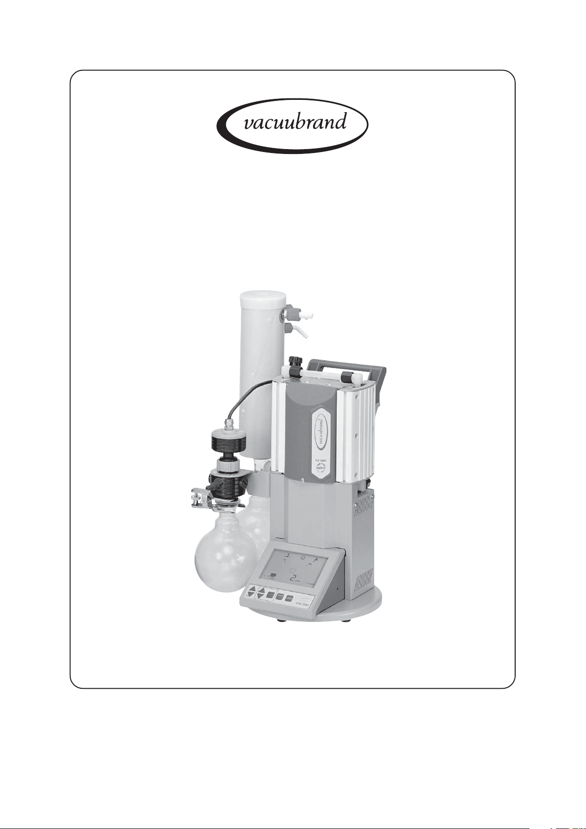
PC 2001 VARIO
Chemistry pumping units with speed control
Documents are only to be used and distributed completely and unchanged. It is strictly the users´ responsibility to check
carefully the validity of this document with respect to his product. manual-no.: 999100 / 06/05/2008
Page 2

page 2 of 49
Dear customer,
Your VACUUBRAND diaphragm pump shall support you at your work for a long time without any trouble and
with full load output. Thanks to our large practical experience we attained much information how you could
add to an efficient application and to personal safety. Please read these instructions for use prior to the
initial start-up of your pump.
VACUUBRAND diaphragm pumps are the result of many years of experience in construction and practical
operation of these pumps combined with the latest results in material and manufacturing technology.
Our quality maxim is the ”zero fault principle”:
Every delivered diaphragm pump is tested extensively including an endurance run of 18 hours. Due to this
endurance run, also faults, which occur rarely, are reported an can be corrected. Every single diaphragm
pump is tested on achievement of the specification after the endurance run.
Every VACUUBRAND pump leaving our factory achieves the specification. We feel obliged to this
high quality standard.
We are aware that the vacuum pump should not draw a part of the real work and we hope to contribute with
our products to an effective and troublefree realisation of your work.
Yours
VACUUBRAND GMBH + CO KG
After sales service: Contact your local dealer or call +49 9342 808-193.
Documents are only to be used and distributed completely and unchanged. It is strictly the users´ responsibility to check
carefully the validity of this document with respect to his product. manual-no.: 999100 / 06/05/2008
Page 3
page 3 of 49
Contents
Safety information! ....................................................................................................4
Technical data ............................................................................................................ 7
Description ..............................................................................................................10
Use and operation ...................................................................................................12
General view modes ................................................................................................16
How to configurate the controller ..........................................................................17
General view mode vacuum control ......................................................................20
Mode vacuum control ............................................................................................. 21
Mode continuous pumping .................................................................................... 25
General view mode VACUU•LAN ............................................................................27
Mode VACUU•LAN ..................................................................................................28
Accessories .............................................................................................................30
Troubleshooting ...................................................................................................... 31
Readjustment ..........................................................................................................33
How to determine the best distillation conditions ................................................34
Interface parameters ............................................................................................... 35
Read commands .....................................................................................................36
Write commands......................................................................................................37
Replacing diaphragms and valves ........................................................................38
Cleaning and assembling components.................................................................44
Calibration in the factory.........................................................................................45
Notes on return to the factory ................................................................................ 46
Health and safety clearance form ..........................................................................47
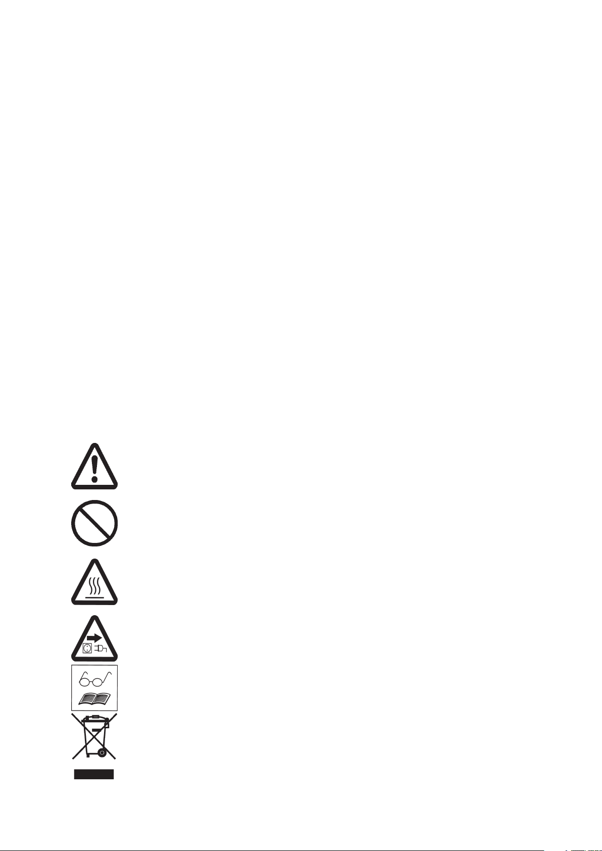
Attention! Important notes!
Not permitted! Misuse may cause damage.
Caution! Hot surface!
Isolate equipment from mains.
Note.
Documents are only to be used and distributed completely and unchanged. It is strictly the users´ responsibility to check
carefully the validity of this document with respect to his product. manual-no.: 999100 / 06/05/2008
Page 4
Safety information!
Remove all packing material, remove the product from its packing-box, remove the
protective covers from the inlet and outlet ports and keep, inspect the equipment.
If the equipment is damaged, notify the supplier and the carrier in writing within three
days; state the item number of the product together with the order number and the
supplier’s invoice number. Retain all packing material for inspection.
Do not use the equipment if it is damaged.
If the equipment is not used immediately, replace the protective covers. Store the
equipment in suitable conditions.
☞ Read and comply with this manual before installing or operating the equip-
ment.
☞ Transport the pump at the provided handle.
Use the equipment for the intended use only (for generation and measurement of
vacuum).
☞☞
☞ Prevent any part of the human body from coming in contact with vacuum.
☞☞
☞ Comply with notes on correct vacuum and electrical connections, see section ”Use
and operation”.
☞ Make sure that the individual components are only connected, combined and oper-
ated according to their design and as indicated in the instructions for use.
page 4 of 49
Comply with national safety regulations and safety requirements concerning the
use of vacuum and electrical equipment.
☞ The mains switch for the controller and the pump is at the rear side of the controller.
☞ After switching off the pump, wait 60 sec. minimum until next switching on.
☞ Equipment must be connected only to a suitable fused and protected electrical
supply and a suitable earth point. Failure to connect the pumping unit to ground
may result in deadly electrical shock.
☞ The supply cable may be fitted with a moulded European IEC plug or a plug suitable
for your local electrical supply. If the plug has been removed or has to be removed,
the cable will contain wires colour coded as follows: green or green and yellow:
earth; blue or white: neutral; brown or black: live.
☞ Check that mains voltage and current conform with the equipment (see rating plate).
☞ If the equipment is brought from cold environment into a room for operation, allow
the equipment to warm up (pay attention to water condensation on cold surfaces).
☞ Make sure ventilation is adequate if pump is installed in a housing or if ambient
temperature is elevated.
Comply with all relevant safety requirements (regulations and guidelines) and adopt
suitable safety measures.
☞ Provide a firm level platform for the equipment and check that the system to be
evacuated is mechanically stable and that all fittings are secure.
Attention: Flexible elements tend to shrink when evacuated.
Due to the high compression ratio of the pumps, pressure at the outlet port might be
generated being higher than the max. permitted pressure compatible with the mechanical stability of the system.
☞ Comply with maximum permitted pressures and pressure differences, see sec-
tion ”Technical data”. Do not operate the pump with overpressure at the inlet.
Do not permit any uncontrolled pressurizing (e. g. make sure that the exhaust pipeline cannot become blocked). If you have an exhaust-isolation valve, make sure that
you cannot operate the equipment with the valve closed. Risk of bursting!
☞ Ensure that the system design does not allow the exhaust pipeline to become
blocked.
☞ Max. permitted pressure at the pressure transducer: 1.5 bar (absolute).
Documents are only to be used and distributed completely and unchanged. It is strictly the users´ responsibility to check
carefully the validity of this document with respect to his product. manual-no.: 999100 / 06/05/2008
Page 5
page 5 of 49
☞ Ensure that the system design does not allow the coolant outlet pipeline to become
blocked.
☞ Secure coolant hoses at the hose nozzles (e.g. with hose clip) to prevent their
accidental slipping.
☞ Check liquid level in both catchpots regularly and drain condensate in time.
☞ Check the overpressure safety relief device at the exhaust waste vapour condenser
in appropriate intervals.
☞ Avoid overpressure of more than 0.2 bar in case inert gas is connected.
☞ The diameter of the inlet and outlet pipeline should be at the least as large as the
diameter of the pump connection pipelines.
To the best of our knowledge the equipment is in compliance with the requirements of
the applicable EC-directives and harmonized standards (see “Declaration of conformity”) with regard to design, type and model, especially directive IEC 1010. This directive
gives in detail conditions, under which the equipment can be operated safely (see also
IP degree of protection).
☞ Adopt suitable measures in case of differences, e. g. using the equipment outdoors,
installation in altitudes of more than 1000 m above mean sea level, conductive
pollution or dewiness.
Pay attention to symbol “hot surfaces“ on the equipment (according to IEC 1010 recommendation).
☞ Adopt suitable measures to prevent any danger arising from the formation of hot
surfaces or electric sparks.
The pumps have no approval for operation in or for pumping of potentially explosive atmospheres.
If pumping different substances, purge the pump with inert gas prior to changing the
pumped media in order to pump out residues and to avoid reactions of the pumped
substances with each other with and the pump material.
Take into consideration interactions and chemical reactions of the pumped media.
The pumps are not suitable for pumping substances which may form deposits inside
the pump.
☞ If there is a danger of the formation of deposits in the pump chamber (check inlet
and outlet of the pump) inspect the pump chamber regularly and clean if necessary.
The pumps are not suitable to pump unstable substances and substances which
react explosively under impact (mechanical stress) and/or when being exposed to
elevated temperatures without air.
The pumps are not suitable to pump self inflammable substances, substances which
are inflammable without air and explosive substances.
The pumps are not suitable for pumping dust and have no approval for operation
below ground.
Ensure that the materials of the wetted parts are compatible with the pumped substances, see section “Technical data”.
☞ Adopt suitable measures to prevent the release of dangerous, explosive, corrosive
or polluting fluids.
☞ Use inert gas for gas ballast if necessary.
☞ The user must take suitable precautions to prevent any formation of explosive
mixtures in the pump. In case of a diaphragm crack, mechanically generated sparks,
hot surfaces or static electricity may ignite these mixtures.
☞ Take adequate precautions to protect people from the effects of dangerous sub-
stances, wear appropriate safety-clothing.
☞ Comply with applicable regulations when disposing of chemicals. Take into consid-
eration that chemicals may be polluted.
The motor is protected by a temperature sensor at the circuit board: Current limitation if the temperature at the circuit board is higher than 70°C, switching off the pump
if the temperature is higher than 85°C.
Documents are only to be used and distributed completely and unchanged. It is strictly the users´ responsibility to check
carefully the validity of this document with respect to his product. manual-no.: 999100 / 06/05/2008
Page 6
page 6 of 49
In case of blockade of the motor (after 10 attempts to start-up) the pump is switched off.
☞ If the pump is switched off due to safety measures, manual reset is necessary.
Isolate the pump from mains. Eliminate cause of failure before restarting the pump.
☞ Avoid high heat supply (e. g. due to hot process gases).
☞ Ensure sufficient air admittance if pump is installed in a housing.
Due to the residual leak rate of the equipment, there may be an exchange of gas,
albeit extremely slight, between the environment and the vacuum system.
☞ Adopt suitable measures to prevent contamination of the pumped substances or
the environment.
Pumping at high inlet pressure may lead to overpressure at the gas ballast valve.
☞ Pumped gases or condensate might be pushed out if the valve is open.
☞ If an inert gas supply is connected, ensure that the inlet pipeline is not contaminated.
The controller is equipped with a short circuit proof transformer with an integrated
overload protection (no fuses).
☞ Failure of the pump (e. g. by power failure) or connected components, parts of the
supply (e. g. coolant) or change of parameters (e. g. increase of pressure in the coolant
system) must not lead to a critical dangerous situation under any circumstances.
Electronic equipment is never 100% fail-safe. This may lead to an indefinite status of
the equipment. Provide protective measures against misfunction and failure.
☞ Operating the pump with high or low frequency, stand still of the pump or operating
the venting valve must not lead to a critical dangerous situation under any circum-
stances.
Ensure that in case of failure the pump and the vacuum system always will turn into a
safe status.
☞ In case of diaphragm cracks or leaks in the manifold pumped substances might be
released into the environment or into the pump housing. To reduce the risk of leaks,
ask for a diaphragm pump with additional safety diaphragm.
☞ Comply especially with notes on operation and use and maintenance.
Use only genuine spare parts and accessories.
☞ Otherwise safety and performance of the equipment as well as the electromagnetic
compatibility of the equipment might be reduced.
☞ Possibly the CE mark or the C/US conformity becomes invalid if not using genuine
spare parts.
Ensure that maintenance is done only by suitably trained and supervised technicians.
Ensure that the maintenance technician is familiar with the safety procedures which
relate to the product processed by the vacuum system and that the equipment, if
necessary, is appropriately decontaminated before starting maintenance.
Comply with local and national safety regulations.
Wear parts have to be replaced regularly. In case of normal wear the lifetime of the
diaphragms and valves is > 10000 operating hours. Bearings have a typical durability
of 40000 h.
Before starting maintenance vent the system, isolate the pump and other components
from the vacuum system and the electrical supply, drain condensate and allow sufficient cooling of the pump.
Before starting maintenance, wait two minutes after isolating the equipment from mains
to allow the capacitors to discharge.
Never operate the pump if covers or other parts of the pump are disassembled.
Never operate a defective or damaged pump.
Repair of the gauge head VSK 5 is not possible.
In order to comply with law (occupational, health and safety regulations, safety at work
law and regulations for environmental protection) vacuum pumps, components and
measuring instruments returned to the manufacturer can be repaired only when certain
procedures (see section “Notes on return to the factory“) are followed.
Documents are only to be used and distributed completely and unchanged. It is strictly the users´ responsibility to check
carefully the validity of this document with respect to his product. manual-no.: 999100 / 06/05/2008
Page 7
page 7 of 49
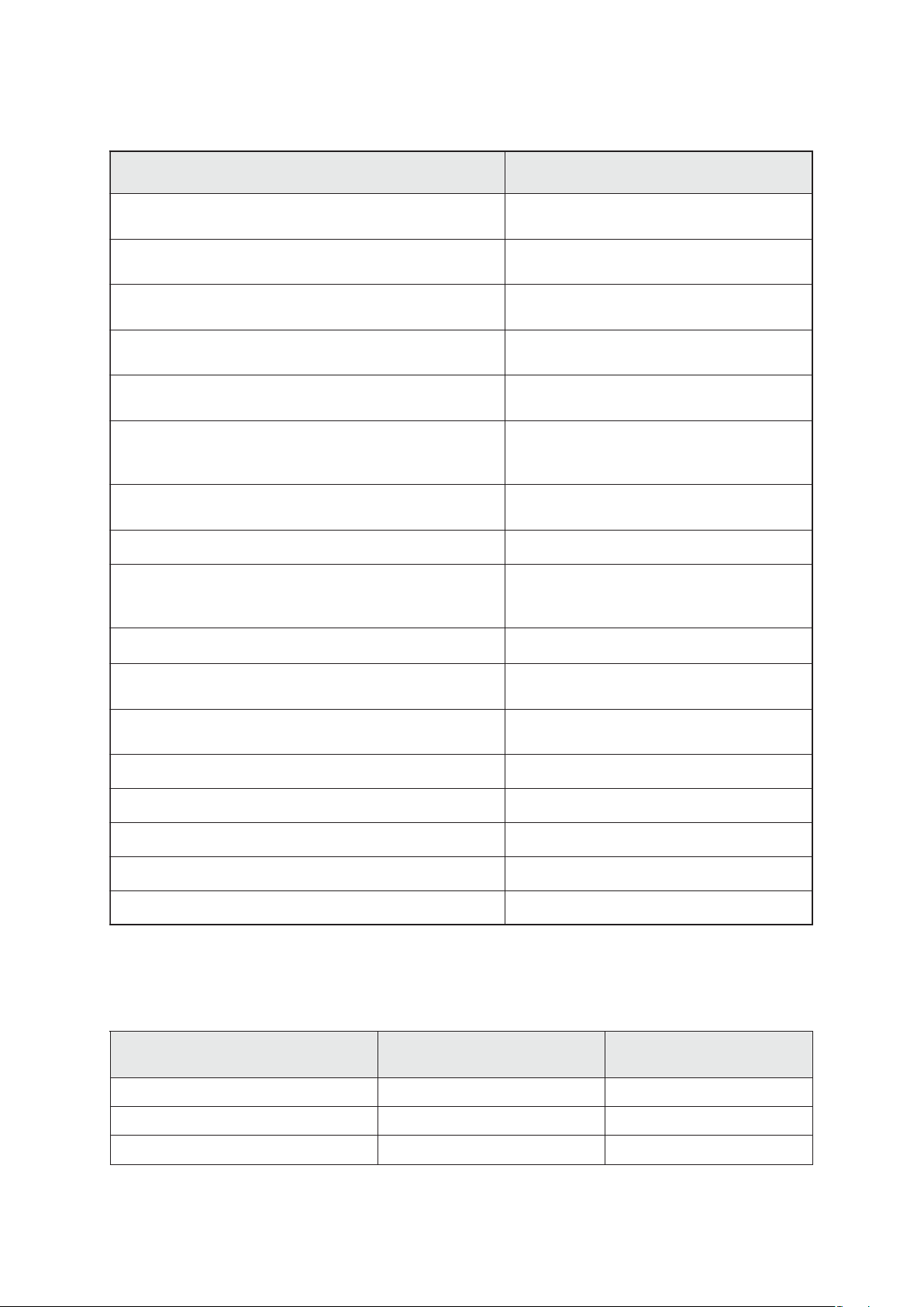
Technical data
epyT OIRAV1002CP
deepsgnipmupmumixaM
)06312OSIotgnidrocca(
ta)etulosba(muucav)latot(etamitlU
'IHgnipmupsuounitnoc'
htiw)etulosba(muucav)latot(etamitlU
'IHgnipmupsuounitnoc'tatsallabsag
teltuoehttaerusserpdettimrep.xaM
)etulosba(
sagehttaerusserpdettimrep.xaM
)etulosba(tsallab
taerutarepmettneibmadettimreP
egarots
noitarepo
erutsiomcirehpsomtaevitalerdettimreP
)noitasnednocon(noitarepognirud
*deepsdaol-oNnim
tnerrucdetaR
~V001
~V032
wardrewoPWk61.0
3
m
h/7.1
rabm2
rabm4
rab1.1
rab2.1
C°
C°
%58ot03
1-
A
A
06+ot01-
04+ot01+
0022-0
6.1
7.0
ylppusegatlovfoegnardettimrep.xaM
)!etalpgnitarees(
noitcetorprotoM tnerruc(bcpehtnorosneserutarepmet
)noitatimil
noitcetorpfoeergeD 02PI
telnI 01/6WNelzzonesoh
teltuO 01WNelzzonesoh
.xorppaHxWxLsnoisnemiDmm274x592x613
.xorppathgieWgk1.01
* Note:
In the motor speed range between 0 and 350 rpm the pump is running automatically in a clocked
interval operation.
zH06/05%01-/+~V032
Gas inlet temperatures:
noitidnocgnitarepO erusserptelnI
noitareposuounitnoC)daolsaghgih(rabm001>
noitareposuounitnoC)daolsagwol(rabm001<
➨ C°04+otC°01+
➨ C°06+otC°0
zH06/05%01-/5+~V021-001
sagfoegnardettimreP
telnitaserutarepmet
)setunim5<(noitarepoemit-trohS)daolsagwol(rabm001<
➨ C°08+otC°01-
We reserve the right for technical modifications without prior note!
Documents are only to be used and distributed completely and unchanged. It is strictly the users´ responsibility to check
carefully the validity of this document with respect to his product. manual-no.: 999100 / 06/05/2008
Page 8
page 8 of 49
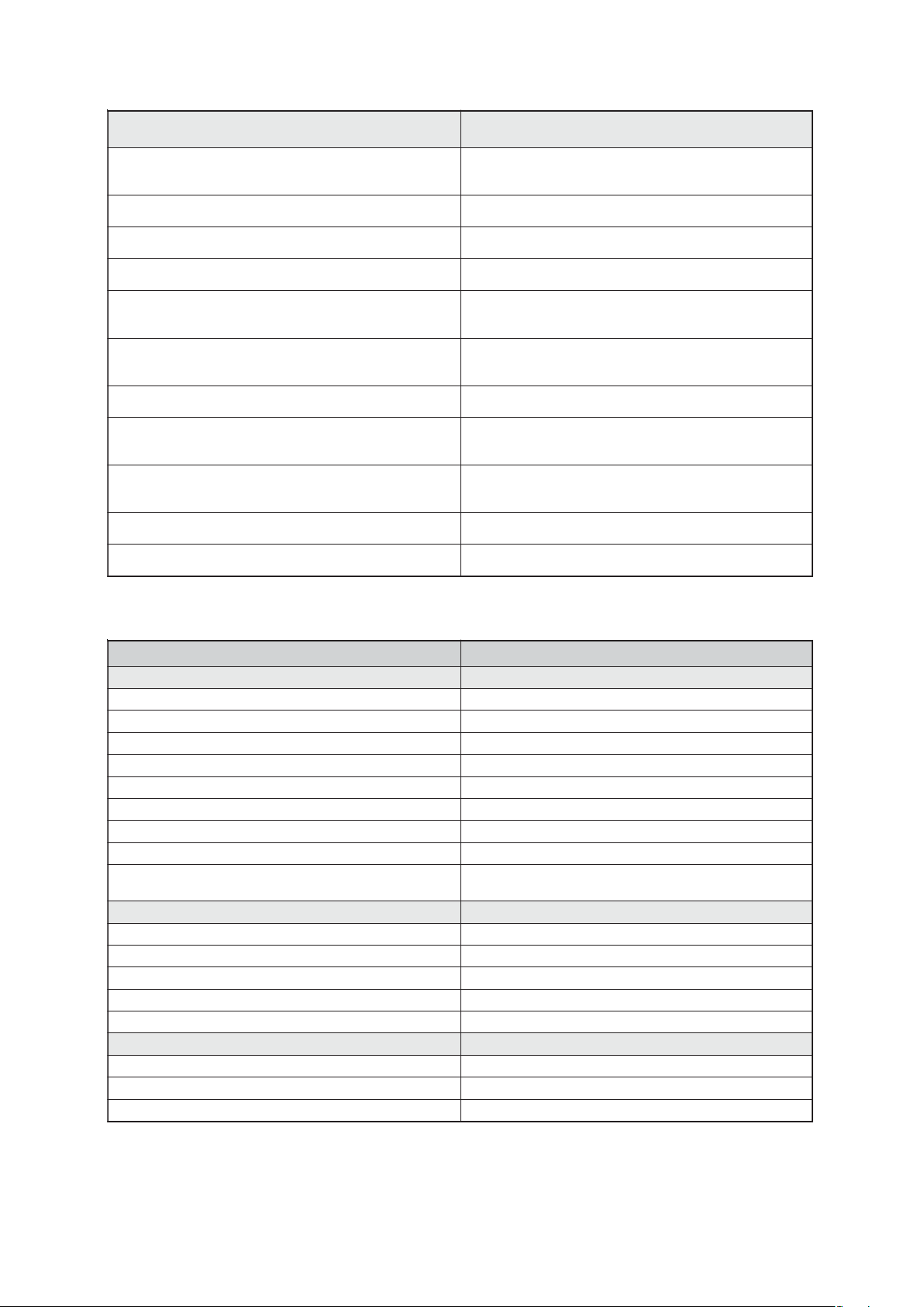
rellortnoC 0002CVC
recudsnarterusserP erusserpetulosbaeviticapac,lanretxe
)neewtebdehctiwsebot(elacs/stinuerusserP aPhrorroT,rabm
egnartnemerusaeM )rroT528-rroT1(rabm0011-rabm1
*egnarlortnocerusserp.xaM )rroT597-rroT1(rabm0601-rabm1
rotomehtfoegnarycneuqerfnoitarepO zH5.0fospetstazH0.06-0.1
ylluferacrecudsnarthtiw(ytniatrecnU
)erutarepmettnatsnoctadnadetarbilac
tneiciffeocerutarepmeT )K/rroT50.0(K/rabm70.0-/+<
recudsnarterusserpnoitcetorpfoeergeD
925CEIotgnidrocca
erusserpehttaerusserpdettimrep.xaM
)etulosba(recudsnart
aidemsuoesagfoerutarepmetdettimrep.xaM C°08otpusdoireptrohsrof
ecafretnilaireS C232SR
II
cimarecedixomuinimulafoedamrecudsnart
)zH57.xam("IH"lanoitiddadna
tigid1-/+)rroT1(rabm1-/+<
45PI
)rroT5211(rab5.1
* The actual vacuum control range in your special application might be reduced due to ultimate vacuum of the pump, quantity of gas occurring etc.
stnenopmoC strapdetteW
tinugnipmuP
teltuOTEP
telnISPP
esoHEFTP
gnittiFEFTE
tophctacehttasgnir-OMPF
ecivedfeilerytefaserusserprevOrebburenocilis
etalprevoctophctaCPP
recudsnarterusserpotnoitcennoCPP
gnitcelloc,resnednocruopavetsawtsuahxE
ksalf
pmuP
tresnirevocgnisuoHEFTP
revocdaeHEFTE
csidgnipmalcmgarhpaiDnobrac/EFTE
evlaVMKFF
mgarhpaiDEFTP
5KSV
laeS remotsaleoroulftnatsiseryllacimehc
gnisuohrecudsnarterusserP leetssselniatsnodecrofniercitsalporudEFTP
recudsnarterusserP cimarecedixomuinimulA
ssalgetacilisorob
We reserve the right for technical modifications without prior note!
Documents are only to be used and distributed completely and unchanged. It is strictly the users´ responsibility to check
carefully the validity of this document with respect to his product. manual-no.: 999100 / 06/05/2008
Page 9
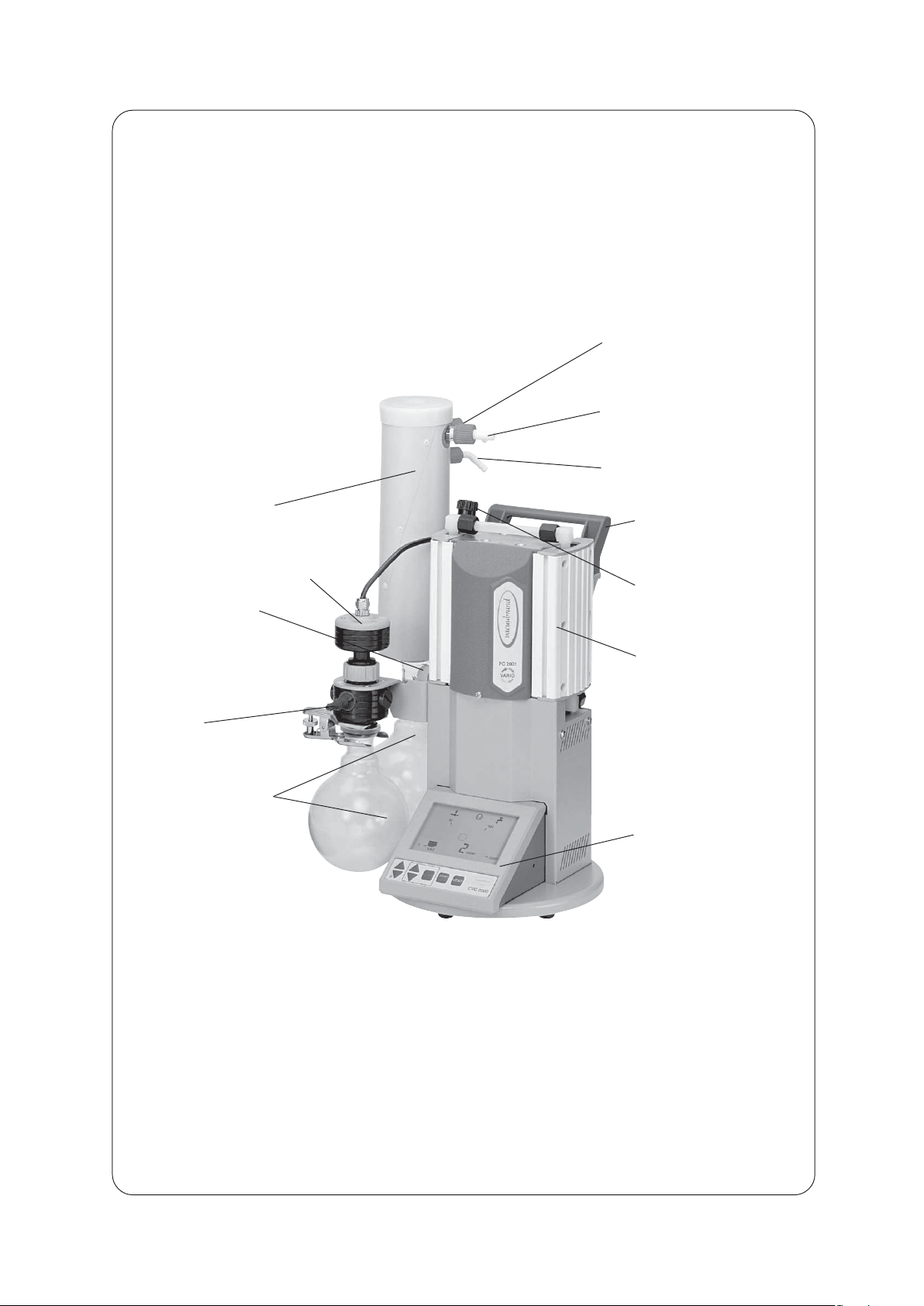
PC 2001 VARIO
exhaust waste vapour
condenser with cover
page 9 of 49
coolant outlet
(hose nozzle 6 mm)
outlet
(gas!; hose nozzle 10 mm)
coolant inlet
(hose nozzle 6 mm)
handle
pressure transducer VSK 5
overpressure safety
relief device at the
exhaust waste
vapour condenser
inlet (vacuum
connection)
round bottom flask to
collect condensate
gas ballast
pump MD 1C VARIO
controller CVC 2000
II
Documents are only to be used and distributed completely and unchanged. It is strictly the users´ responsibility to check
carefully the validity of this document with respect to his product. manual-no.: 999100 / 06/05/2008
Page 10
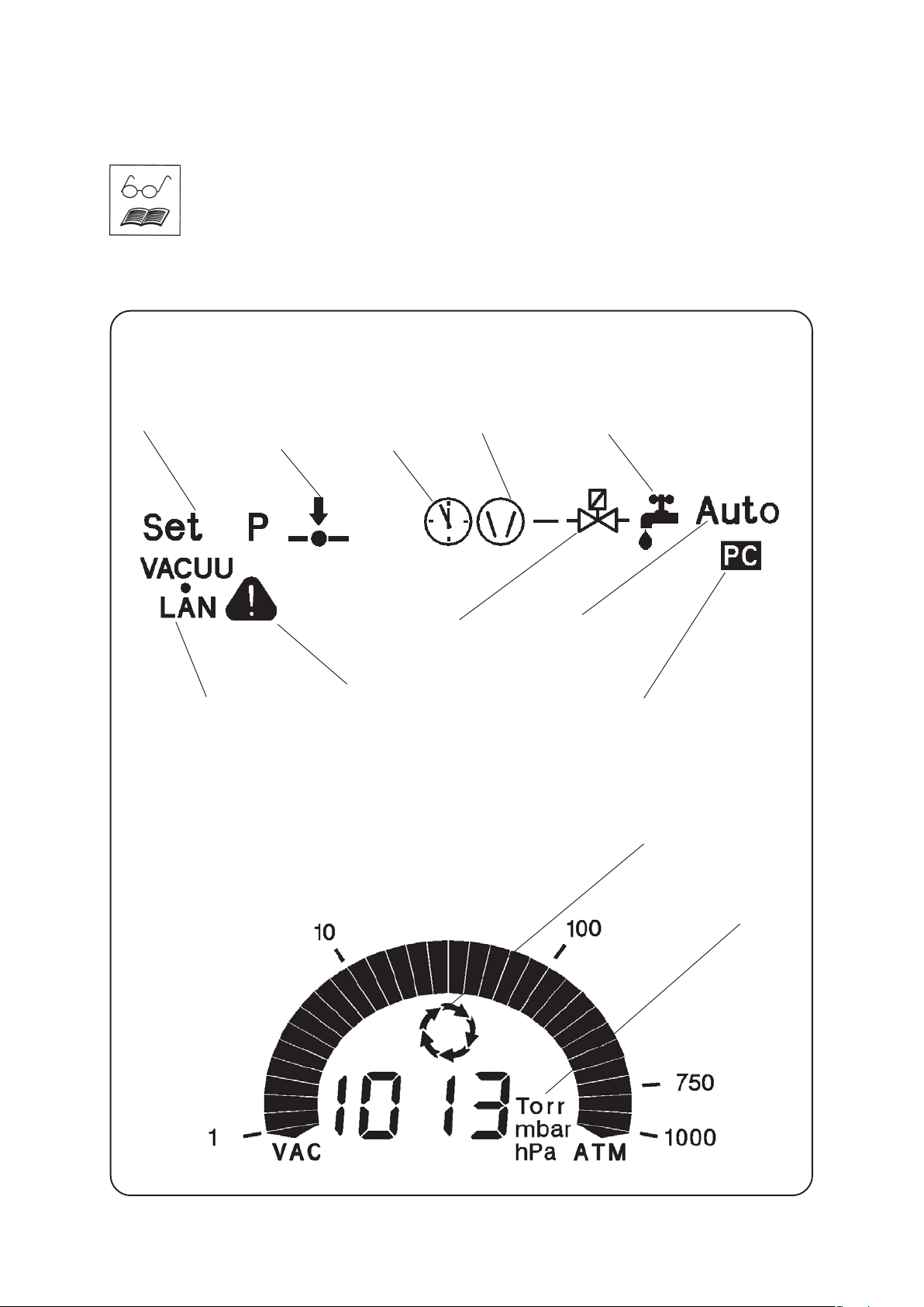
Description
The controller can be adapted to the specific application by choosing another mode
than ”Vacuum control” (factory-set), see section ”General view modes”.
The status of the controller respectively of the connected accessories is displayed by
corresponding symbols on the LCD. After switching on the version of the software is
displayed, than the mode as well as the symbols “coolant valve” and “venting valve”, if
the valves are preselected.
General view display
page 10 of 49
modes coolant valvepump symboltime
mode VACUU•LAN
mode vacuum control or
continuous pumping
warning (in combination with
other symbols)
counter
venting valve
Pressure reading
automatic mode
remote operation
process control
active
selectable
pressure units
Documents are only to be used and distributed completely and unchanged. It is strictly the users´ responsibility to check
carefully the validity of this document with respect to his product. manual-no.: 999100 / 06/05/2008
Page 11
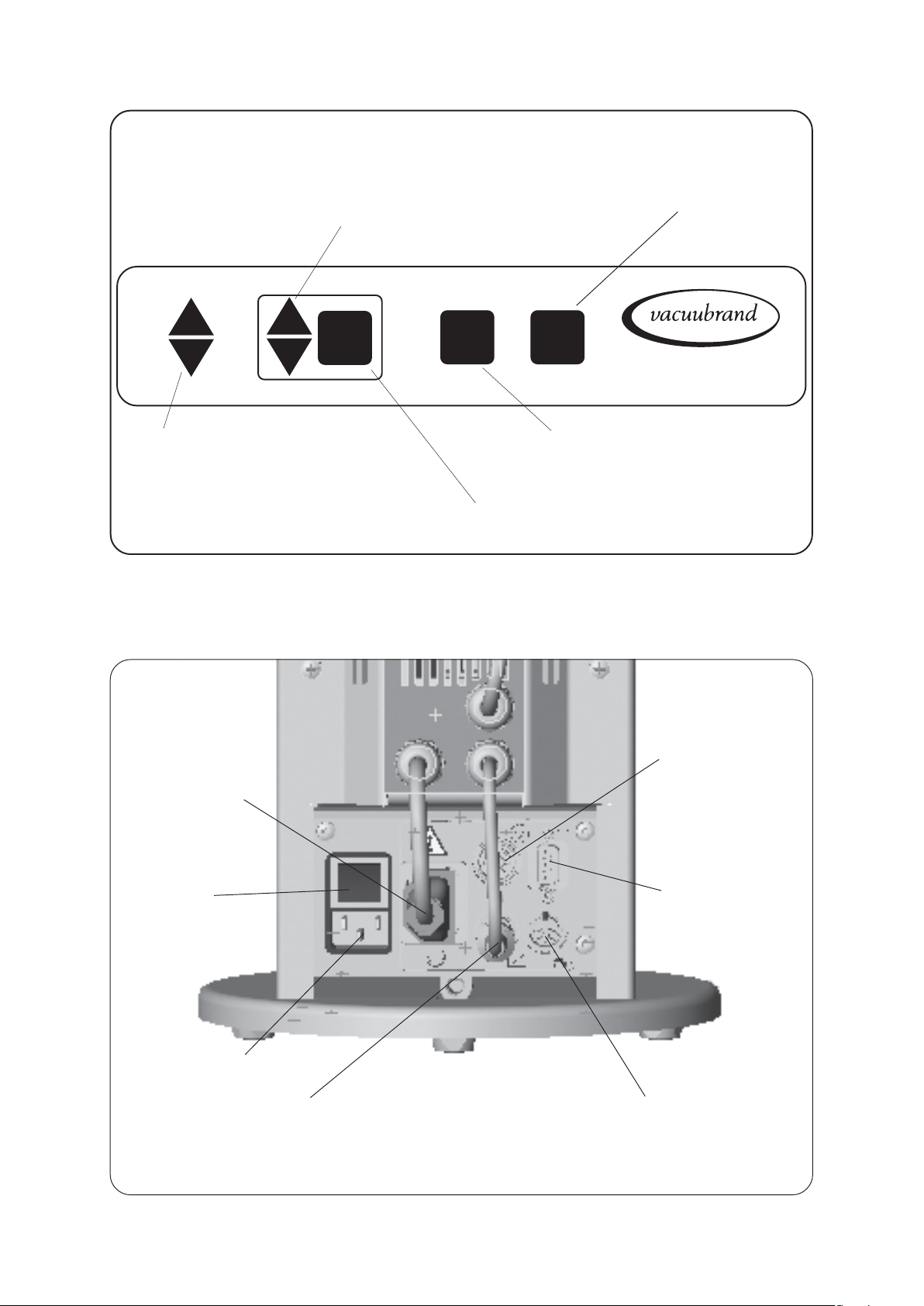
Keys
page 11 of 49
• setting of frequency
• setting time for switch-off (only VACUU•LAN)
• switching (toggling) in modes
MODE
p
• pressure setting (only vacuum control)
• adapting process pressure
• switch on/off automatic mode (only vacuum control)
• special function (in combination with another key)
operating venting valve (only if
valve is connected and preselected)
START
STOP
VENT
CVC 2000
start or stop of process control or
confirmation of selected values or mode
II
Rear side
CVC 2000
connection pump
supply
mains switch
connection mains
cable
female connector to connect
pump electronics
II
female connector
to connect the gauge
head VSK 5
serial interface
RS 232 C
female connector to connect a coolant
valve and/or an venting valve
Documents are only to be used and distributed completely and unchanged. It is strictly the users´ responsibility to check
carefully the validity of this document with respect to his product. manual-no.: 999100 / 06/05/2008
Page 12
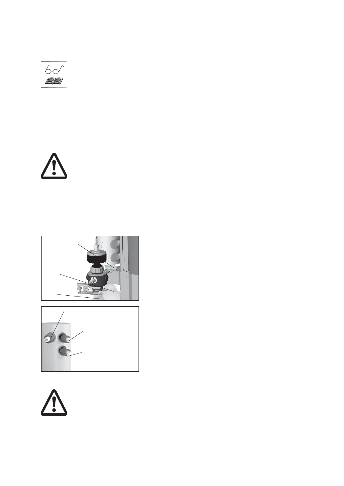
Use and operation
Installing in a vacuum system:
☞ Avoid throttling losses by using connecting pipes with large diameter and keep
them as short as possible.
☞ Reduce the transmission of vibration and prevent loading due to rigid pipelines.
Insert elastic hoses or flexible elements as couplings between the pump and rigid
pipes. Attention: Flexible elements tend to shrink when evacuated.
☞ Use a suitable valve to isolate the pump from the vacuum system to allow the
pump to warm up before condensable vapours are pumped or to clean the pump
before it is switched off.
☞ Connect the exhaust to a suitable treatment plant to prevent the discharge of dan-
gerous gases and vapours to the surrounding atmosphere. Use a catchpot to prevent the drainage of contaminated condensate back into the pump.
Prior to use:
☞ Max. ambient temperature: 40 °C
☞ Make sure ventilation is adequate if pump is installed in a housing or if ambient
temperature is elevated.
☞ If pump is installed in altitudes of more than 1000 m above mean sea level check
compatibility with applicable safety requirements, e. g. IEC 60034 (motor may overheat due to insufficient cooling).
☞ When assembling, ensure vacuum-tightness. After assembly, check the complete
system for leaks.
page 12 of 49
overpressure
safety relief
device
flask at the
outlet
flask at the
inlet
outlet
(gas!; hose nozzle 10 mm)
Separator at the inlet and exhaust waste vapour condenser at the outlet:
Round bottom flasks:
The catchpot at the inlet prevents droplets and particles from
entering the pump.
☞ Lifetimes of diaphragms and valves are enhanced.
☞ Improves vacuum in case of condensation.
Both round bottom flasks are coated with a protective layer to
prevent disintegration in case of breakage or implosion.
➨ Assemble the catchpots at the inlet and at the outlet using
joint clips.
Exhaust waste vapour condenser:
➨ Assemble hose nozzles for coolant inlet and coolant outlet
pipelines at the exhaust waste vapour condenser.
coolant outlet
(hose nozzle 6 mm)
coolant inlet
(hose nozzle 6 mm)
➨ Attach the pipelines of the coolant circuit to the respective hose nozzles (see im-
age) at the waste vapour condenser. Check hose connections prior to starting operation of the cooling system.
☞ Secure coolant hoses at the hose nozzles (e.g. with hose clip) to prevent their
accidental slipping.
➨➨
➨ Attention: Install hoses of the cooling system in a way to avoid flow / drop-
➨➨
ping of condensed water to the pumping unit (especially cables and electronic parts).
☞ Ensure that the coolant outlet pipeline is always free and that it cannot get blocked.
The exhaust waste vapour condenser enables an efficient
condensation of the pumped vapours at the outlet.
☞ No backflow of condensates.
☞ Controlled recovery of condensates.
☞ Next to 100% solvent recovery.
☞ The isolation cover protects against glass splinters in case
of breaking, acts as thermal isolation to avoid condensation
of humidity and is intended to absorb shocks.
Documents are only to be used and distributed completely and unchanged. It is strictly the users´ responsibility to check
carefully the validity of this document with respect to his product. manual-no.: 999100 / 06/05/2008
Page 13
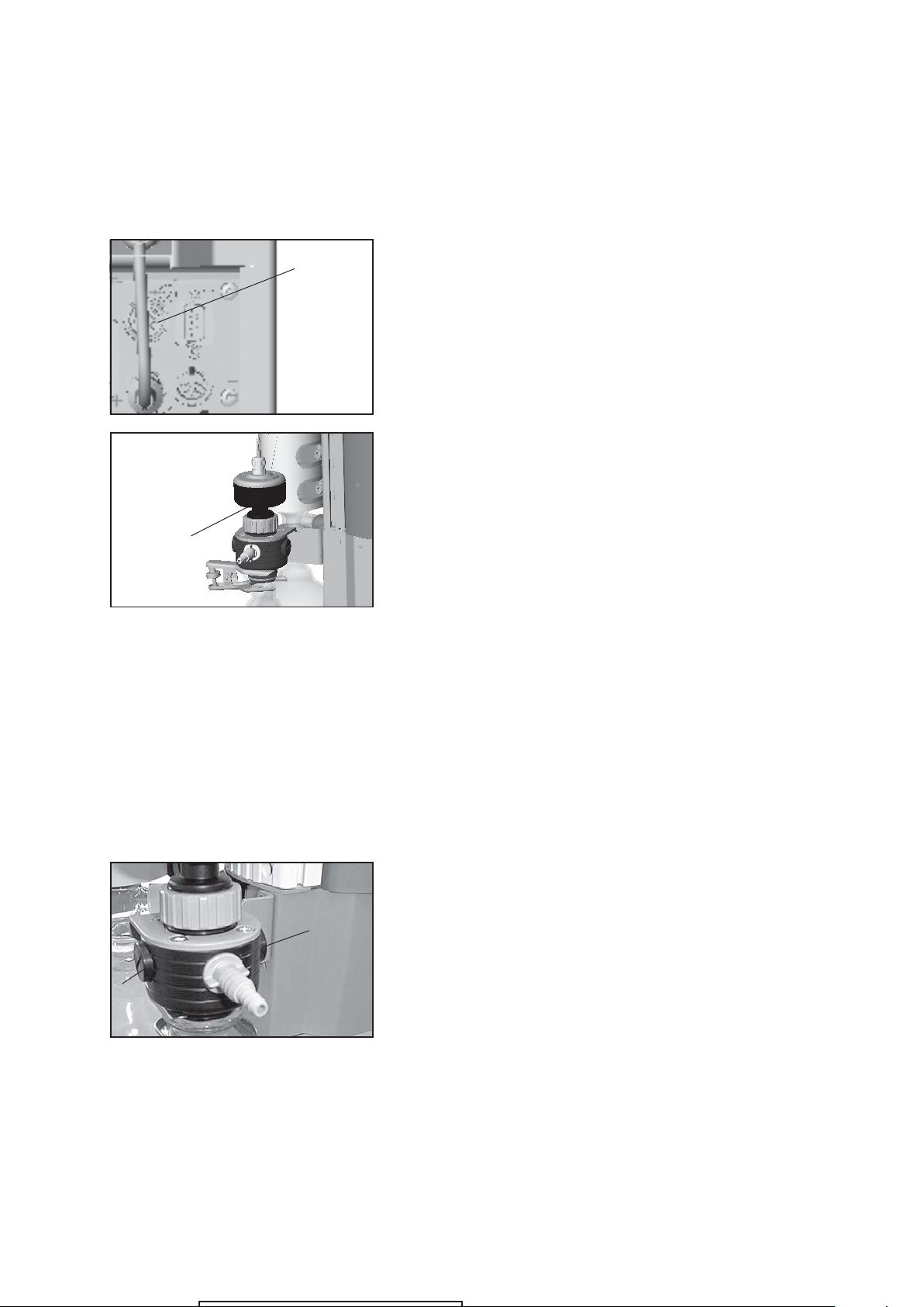
pressure
transducer
VSK 5
page 13 of 49
☞ The gas outlet (hose nozzle 10 mm) must not be blocked. The exhaust pipeline has
always to be free and pressureless to enable an unhindered discharge of gases.
☞ Connect the exhaust to a suitable treatment plant to prevent the discharge of dan-
gerous gases and vapours to the surrounding atmosphere.
Notes regarding the assembling of the pressure transducer VSK 5
The cable of the gauge head is connected to the female conconnector
for VSK 5
nector at the rear side of the vacuum controller.
The gauge head is connected to the vacuum system with a
union nut using an adapter.
☞ The device is adjusted together with the gauge head at the
factory. If the gauge head is replaced a readjustment is recommended.
Max. permitted pressure at the pressure transducer: 1.5 bar (ab-
solute).
☞ The display flashes at a pressure higher than 1100 mbar.
☞ Comply with max. permitted pressure.
☞ Inside a vacuum system where evaporation occurs, e. g.
rotary evaporator, the vacuum is not uniform, e. g. a condenser acts as pump or the vacuum in the pipeline is lower
than in the system. Therefore carefully choose position where
to connect the gauge head.
The pressure transducer can be disassembled from the inlet of the pumping unit and,
after having unscrewed the adapter, assembled using a small flange connection or a
hose nozzle (included in delivery) directly to the apparatus.
Close the connection at the inlet of the pumping unit using a blind cap (cat. no.: 67 71 50).
☞ Condensate and deposits in the pressure transducer affect the measuring result.
☞ In case of deposits, aggressive or condensable media, install a gas washing bottle
before the pressure transducer if necessary.
☞ In order to avoid malfunction it is important to position the pressure transducer in
the vacuum line so as to avoid flow of condensate towards the pressure transducer.
☞ Clean pressure transducer if necessary, see section “maintenance“.
Hose nozzle (inlet of the pumping unit):
☞ Alternatively the hose nozzle or a second hose nozzle (in-
cluded in delivery) can be assembled at position 1 or 2 at
2
the inlet of the pumping unit.
➨ Change closing screw and hose nozzle. Ensure that the O-
ring is correctly positioned.
1
Documents are only to be used and distributed completely and unchanged. It is strictly the users´ responsibility to check
carefully the validity of this document with respect to his product. manual-no.: 999100 / 06/05/2008
Before operation
Page 14
page 14 of 49
During operation:
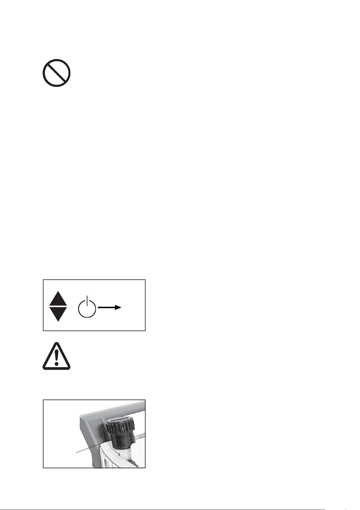
Do not start or operate the pump if pressure at the outlet is higher than 1.1 bar
absolute. Attempts to start or operate the pump at higher pressure may cause block-
ade and damage of the motor.
☞ Comply with max. permitted pressure at the outlet and max. permitted pressure
difference between inlet and outlet.
The pump achieves its pumping speed, ultimate total vacuum and vapour pump-
ing rate only at operating temperature (after approx. 15 minutes).
☞ Prevent internal condensation, transfer of liquids or dust. The diaphragm and valves
will be damaged, if liquids are pumped in significant amounts.
☞ Operate the pump with gas ballast valve open to reduce the condensation of pumped
media (water vapour, solvents, ....) inside the pump.
The motor is protected by a temperature sensor at the circuit board: Current limitation if the temperature at the circuit board is higher than 70°C, switching off the pump
if the temperature is higher than 85°C. In case of blockade of the motor (after 10
attempts to start-up) the pump is switched off.
☞ If the pump is switched off due to safety measures, manual reset is necessary.
Isolate the pump from mains. Eliminate cause of failure before restarting the pump.
☞ Avoid high heat supply (e. g. due to hot process gases).
☞ Ensure sufficient air admittance if pump is installed in a housing.
Settings at the controller
☞ Setting of interface parameters, see section “Interface“.
☞ Preselections at the controller, see section “Modes“.
☞ Use and operation of the controller see section “How to operate the controller”.
How to change the pressure units
Press key p▲ or p▼ during switching on.
☞ The pressure units are displayed, the pressure unit as from
mbar
+
p
Torr
hPa
last operation is flashing.
➨ Press key p▲ or p▼ to change pressure unit. Press key
stop when controller displays the desired pressure unit to
finish the operation mode.
Attention: Important notes regarding the use of gas ballast
☞ Make sure that air/gas inlet through the gas ballast valve never leads to hazardous,
explosive or otherwise dangerous mixtures. If in doubt, use inert gas.
☞ When using air rather than inert gas, risk of significant damage to equipment and/or
facilities, risk of personal injury or even loss of life exists due to the formation of
hazardous and/or explosive mixtures if air and pumped media react inside or at the
outlet of the pump.
For condensable vapours (water vapour, solvents, ...):
☞ Do not pump vapour before pump has reached its operating
temperature and not with gas ballast valve closed.
☞ Open gas ballast valve. Close gas ballast valve by turning
180°.
☞ The gas ballast valve is open if the arrow on the gas ballast
cap points towards the pump.
gas ballast
Documents are only to be used and distributed completely and unchanged. It is strictly the users´ responsibility to check
carefully the validity of this document with respect to his product. manual-no.: 999100 / 06/05/2008
☞ With gas ballast valve open ultimate vacuum will be reduced,
pumping speed is decreased.
☞ Use inert gas at the air inlet to avoid the formation of explo-
sive mixtures.
Page 15
page 15 of 49
In case of low boiling solvents when the formation of condensate is unlikely, the use of
gas ballast might be unnecessary.
☞ Operating the pump without gas ballast increases the solvent recovery rates at the
exhaust waste vapour condenser.
Attention: Notes concerning the operation of the exhaust waste vapour condenser
➨ Check hose connections prior to starting operation of the cooling system.
➨ Check coolant hoses regularly during operation.
☞ Ensure that the coolant outlet pipeline is always free and that it cannot get blocked.
☞ Maximum permissible coolant pressure at the exhaust waste vapour condenser:
6 bar (absolute)
☞ Comply with the maximum permissible coolant pressures of additional components
in the coolant circuit (e.g coolant valve).
☞ Avoid overpressure in the coolant circuit (e.g. caused by blocked or squeezed cool-
ant hoses).
☞ Permissible range of coolant temperature at the exhaust waste vapour condenser:
-15°C to +20°C
☞ The gas outlet (hose nozzle 10 mm) must not be blocked. The exhaust pipeline has
always to be free and pressureless to enable an unhindered discharge of gases.
☞ Connect the exhaust to a suitable treatment plant to prevent the discharge of dan-
gerous gases and vapours to the surrounding atmosphere.
In case of condensation:
➨ Check liquid level in both catchpots during operation. Avoid overflowing of the catchpots.
☞ Do not overfill the catchpots. Maximum liquid level approx. 80%, to avoid problems
when removing the catchpots.
➨ Check liquid level in both catchpots regularly and drain catchpots in time.
Removing the catchpots:
Catchpot at outlet:
➨ Remove joint clip, remove catchpot and drain condensate.
Catchpot at inlet:
➨ Admit air or inert gas (via inlet of pumping unit) to atmospheric pressure. Remove
joint clip, remove catchpot and drain condensate.
➨ Reassemble drained catchpots.
Important: Comply with regulations when disposing solvents/condensates. Reuse if
possible, purify if contaminated.
Shutdown:
Short-term:
Has the pump been exposed to condensate?
☞ Allow the pump to continue to run at atmospheric pressure for a few minutes (con-
tinuous pumping at a setting of 60).
Has the pump been exposed to media which may damage the pump materials or forms
deposits?
☞ Check and clean pump heads if necessary.
Has the pressure transducer been exposed to media which may form deposits?
☞ Clean pressure transducer if necessary.
Long-term:
➨ Take measures as described in section short-term shutdown.
➨ Separate pump from the apparatus.
➨ Close inlet and outlet port (e. g. with transport caps).
➨ Store the pump in dry conditions.
Documents are only to be used and distributed completely and unchanged. It is strictly the users´ responsibility to check
carefully the validity of this document with respect to his product. manual-no.: 999100 / 06/05/2008
Page 16
General view modes
page 16 of 49
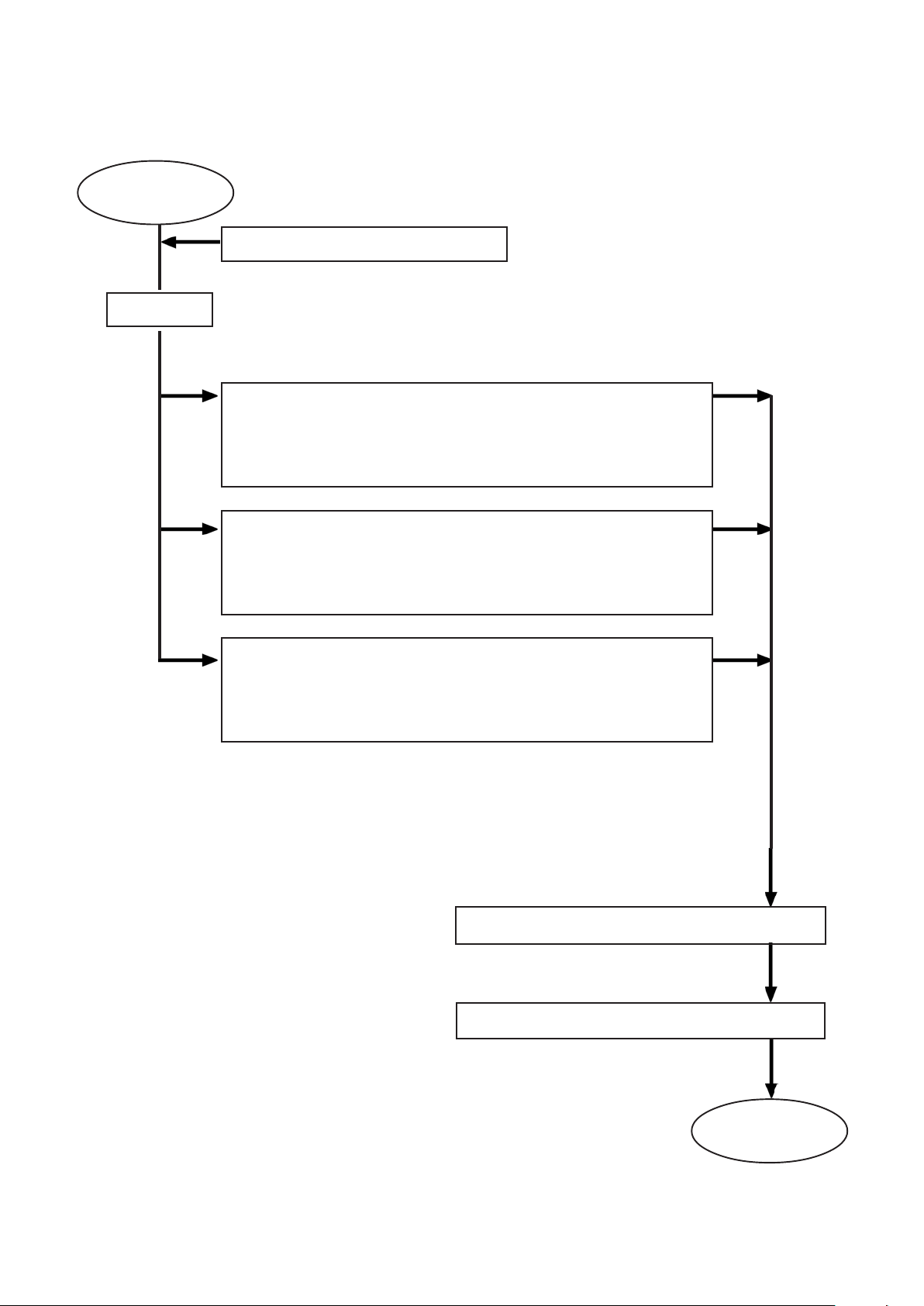
CVC 2000
setting mode
II
setting pressure unit (mbar / Torr / hPa)
mode ”vacuum control”
controller controls
- pump according to preset pressure value or in automatic mode
- coolant valve (optional)
- venting valve (optional)
mode ”continuous pumping”
controller controls
- pump according to preset pumping speed
- coolant valve (optional)
- venting valve (optional)
(factory set)
mode ”VACUU•LAN”
controller controls
- pump according to preset pressure and time values
- coolant valve (optional)
- venting valve (optional)
configuration of the coolant valve if applicable
configuration of the venting valve if applicable
ready to
start
Documents are only to be used and distributed completely and unchanged. It is strictly the users´ responsibility to check
carefully the validity of this document with respect to his product. manual-no.: 999100 / 06/05/2008
Page 17
page 17 of 49
How to configurate the controller
The controller CVC 2000II can be adapted to the specific application by choosing the
appropriate mode, vacuum control with or without automatic, continuous pump-
ing with preset pumping speed or VACUU•LAN: The components of the chemistry
vacuum system (coolant valve, venting valve) have to be preset once only. The mode
as from last operation and the preselected values (e. g. for pressure, speed or time for
switching off) are stored. In case of similar operation conditions it is possible to start
immediately, if the preselections are chosen appropriately.
The vacuum controller CVC 2000II offers three modes depending on
- the components of the VACUUBRAND chemistry vacuum system which are con-
nected to the system.
- the specific user and/or process requirements.
In all modes:
☞ If coolant and/or venting valve have been connected and
preselected:
➨ Process-adapted operation of the coolant valve.
➨ Key-driven venting or adjustment of the set point by venting
if process control is active.
Vacuum control:
➨ Position control on preset pressure value.
➨ The pumping speed is adapted to the occurring gas/vapour,
so that the preset pressure value is kept constant.
➨ Operating in equilibrium by continuous adaption of the con-
troller, no abrupt switching of valves.
Vacuum control in automatic mode:
➨ Searching the boiling point and adjusting the set point auto-
matically if the boiling point changes (due to temperature
change, change of ingredients of solutions).
➨ Adjusting the set point automatically after manual setting of
the boiling point (additional automatic mode in operation mode
vacuum control).
➨ Automatic switching off after complete evaporation of the
solvent if preselected.
Continuous pumping with preset pumping speed:
➨ Simple suction, sucking liquids by siphon, drying, sucking
off excess, etc.
➨ Suction with regulated pumping speed.
➨ Pumping down until the ultimate vacuum of the pump is
achieved (e. g. to dry a system).
➨ System controlled by an interface: temporally variable pump-
ing speed to optimize the process conditions (e. g. to dry
sensitive substances).
➨ Setting ”HI”: Optimum pumping speed at every pressure.
Documents are only to be used and distributed completely and unchanged. It is strictly the users´ responsibility to check
carefully the validity of this document with respect to his product. manual-no.: 999100 / 06/05/2008
Page 18
Setting the mode
MODE
+
(mains switch)
page 18 of 49
VACUU•LAN:
➨ The mode for decentralized vacuum network systems (for
vacuum in laboratories, vacuum lines for weekend, night or
trainee operations). Continuous vacuum without continuous
pumping.
➨ The coolant is switched off if no more pumping is required,
switched on again if gas or vapour occur.
➨ Vacuum supply according to the requirements for lock cham-
bers or pumping systems not compressing against atmospheric pressure, e. g. wide range turbomolecular pumps or
cryo pumps.
➨ Additional extension of the lifetime of diaphragms and valves.
Starting the program:
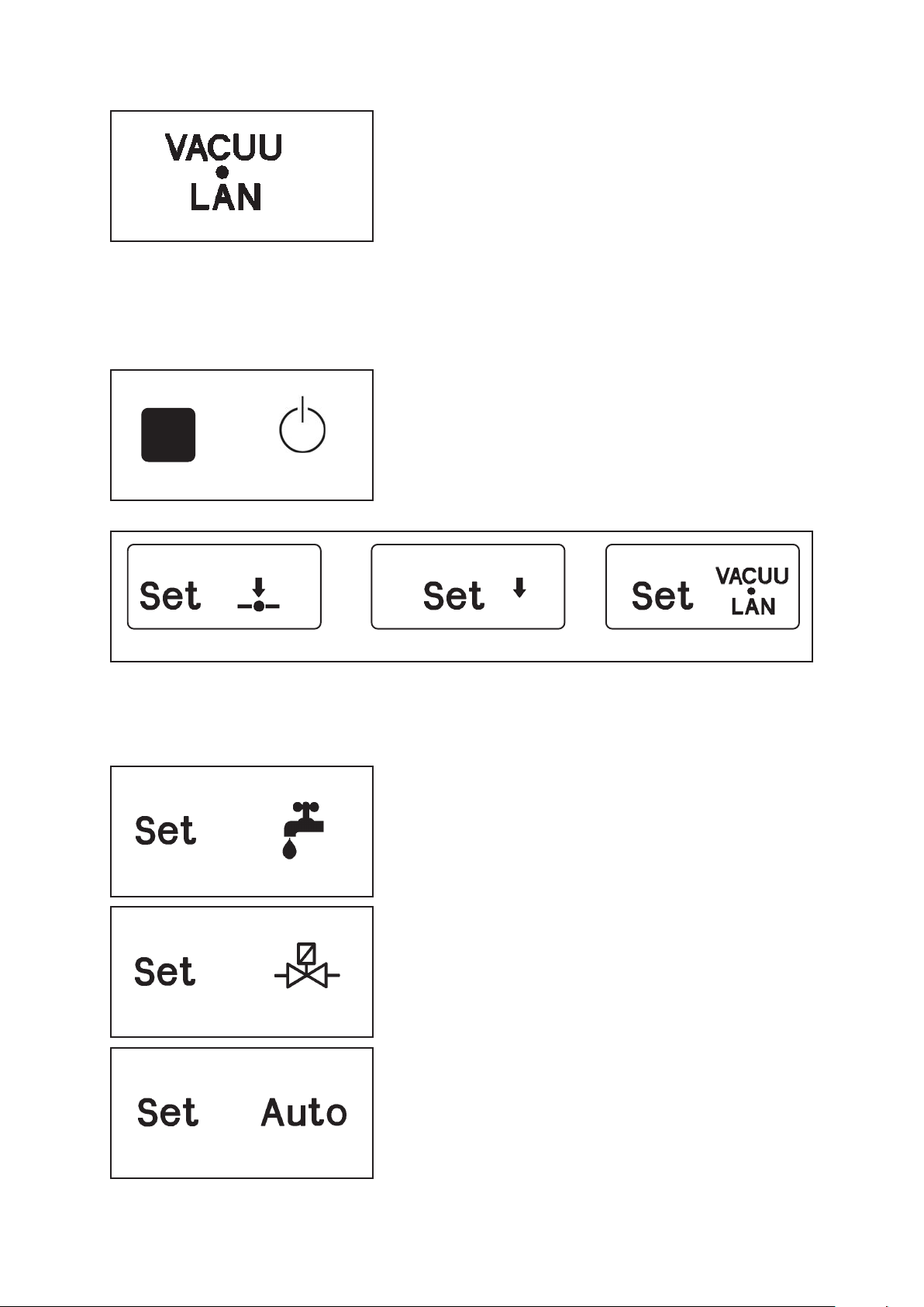
➨ Press key MODE while switching on the controller.
☞ The mode “vacuum control” (factory-set) is displayed on the
LCD by flashing symbols.
To change the mode:
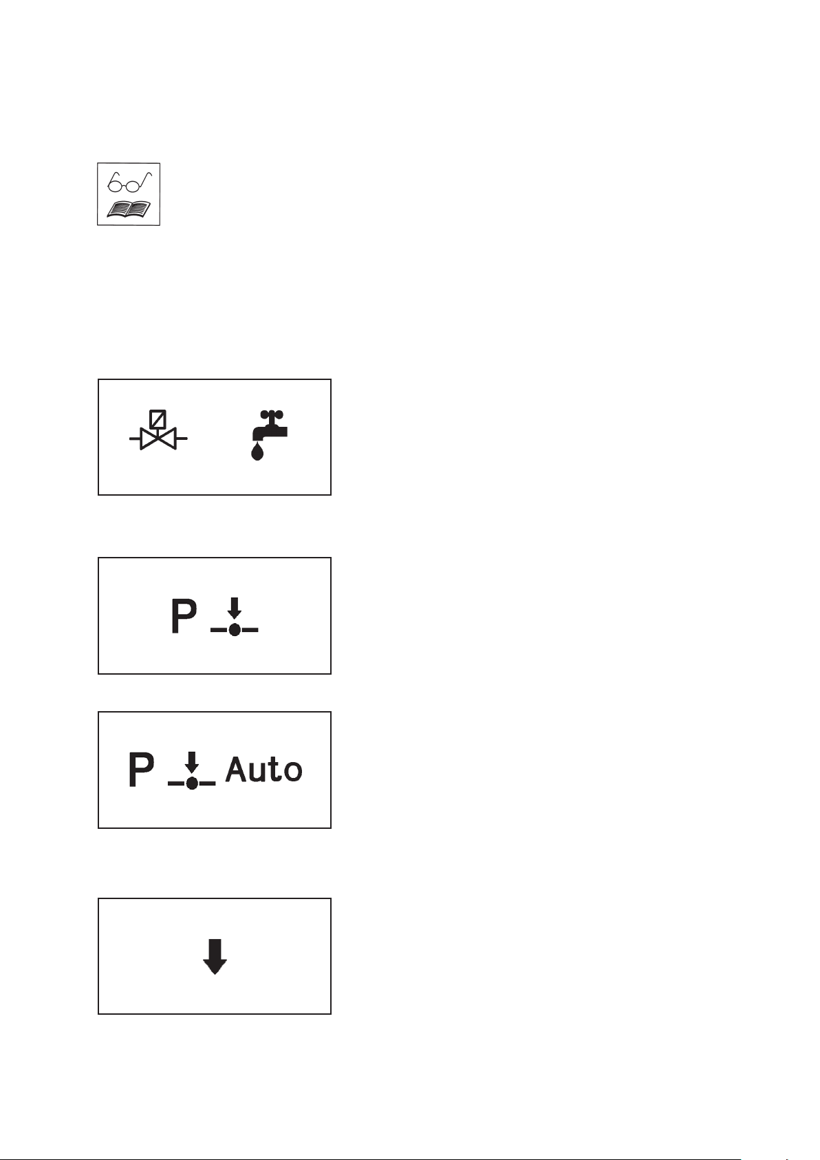
➨ Press key ▲ or ▼ until the symbol of the desired mode is
flashing.
vacuum control continuous pumping VACUU•LAN
➨ Press key START/STOP to confirm the selected mode.
After selecting the mode:
☞ The symbol of the coolant valve is displayed and ”yes” or
”no”.
➨ Switching between ”yes” or ”no” is possible by pressing key
▲ or ▼.
➨ Confirm the selection ”yes” or ”no” by pressing key START/
STOP.
☞ The symbol of the venting valve is displayed and ”yes” or
”no”.
➨ Switching between ”yes” or ”no” is possible by pressing key
▲ or ▼.
➨ Confirm the selection ”yes” or ”no” by pressing key START/
STOP.
Only in mode “vacuum control”:
☞ “Set“, “Auto“ and ”yes” or ”no” are displayed.
➨ Switching between ”yes” or ”no” is possible by pressing key
▲ or ▼.
➨ To preselect the automatic mode confirm ”yes” by pressing
key START/STOP.
➨ If you do not wish to preselect the automatic mode confirm
”no” by pressing key START/STOP.
Documents are only to be used and distributed completely and unchanged. It is strictly the users´ responsibility to check
carefully the validity of this document with respect to his product. manual-no.: 999100 / 06/05/2008
Page 19

page 19 of 49
If the automatic mode has been preselected “End” is displayed.
☞ Switching between automatic switching off activated or not
activated is possible by pressing key ▲ or ▼.
➨ Confirm by pressing key START/STOP.
☞ The controller switches to normal operation mode (process
control not active).
☞ Automatic switching off as soon as the controller detected
that evaporation is completely finished. The pump is switched
off, the coolant is running on, if a coolant valve is prese-
lected.
☞ Without automatic switching off, the pressure in the vacuum
system is adjusted after evaporation is completed if neces-
sary until the ultimate vacuum of the system.
Documents are only to be used and distributed completely and unchanged. It is strictly the users´ responsibility to check
carefully the validity of this document with respect to his product. manual-no.: 999100 / 06/05/2008
Page 20
page 20 of 49
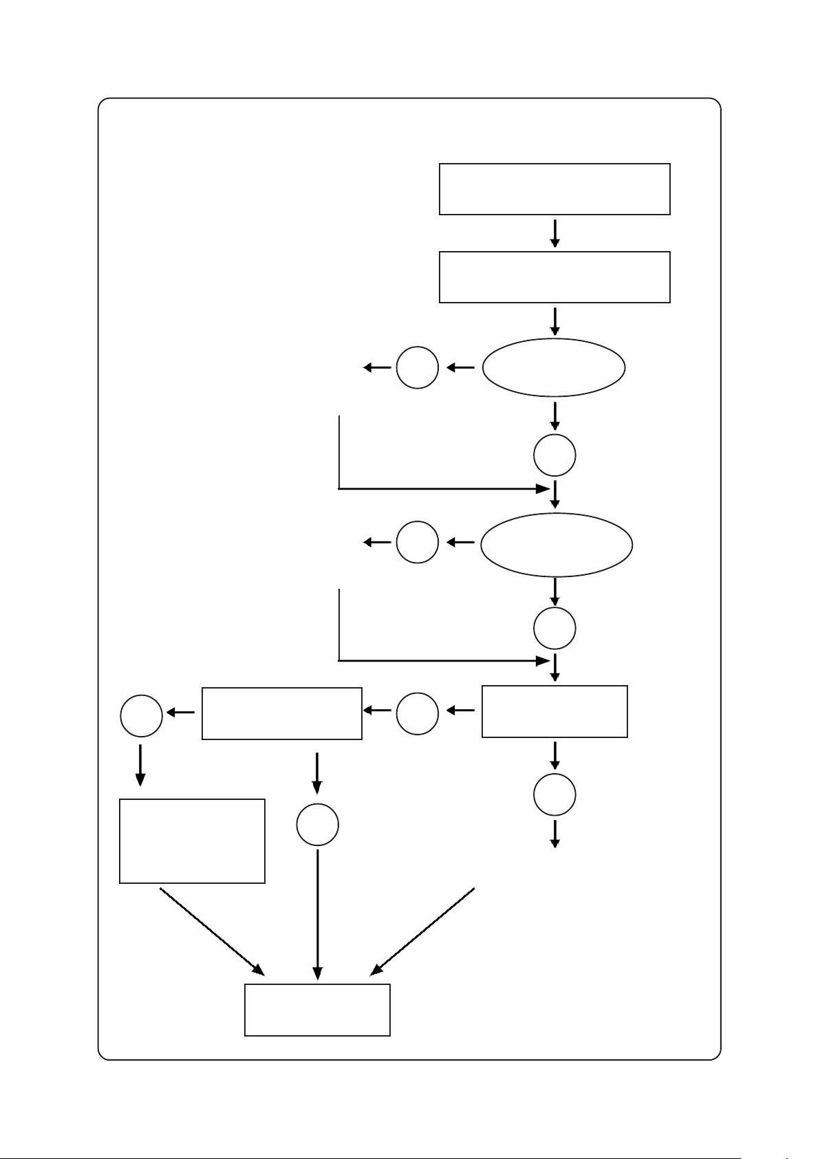
General view mode vacuum control
selection of the mode
mode vacuum control
connect and
configurate
coolant valve
yes
switching coolant
valve?
no
yes
pre-set switching off
at end process?
set pressure for
switching off or
automatic switch-
ing off ”AE”
connect and
configurate
venting valve
no
yes
yes
switching
venting
valve?
no
automatic mode?
no
manual settings:
process pressure and
speed if applicable
process control
Documents are only to be used and distributed completely and unchanged. It is strictly the users´ responsibility to check
carefully the validity of this document with respect to his product. manual-no.: 999100 / 06/05/2008
Page 21
page 21 of 49
Mode vacuum control
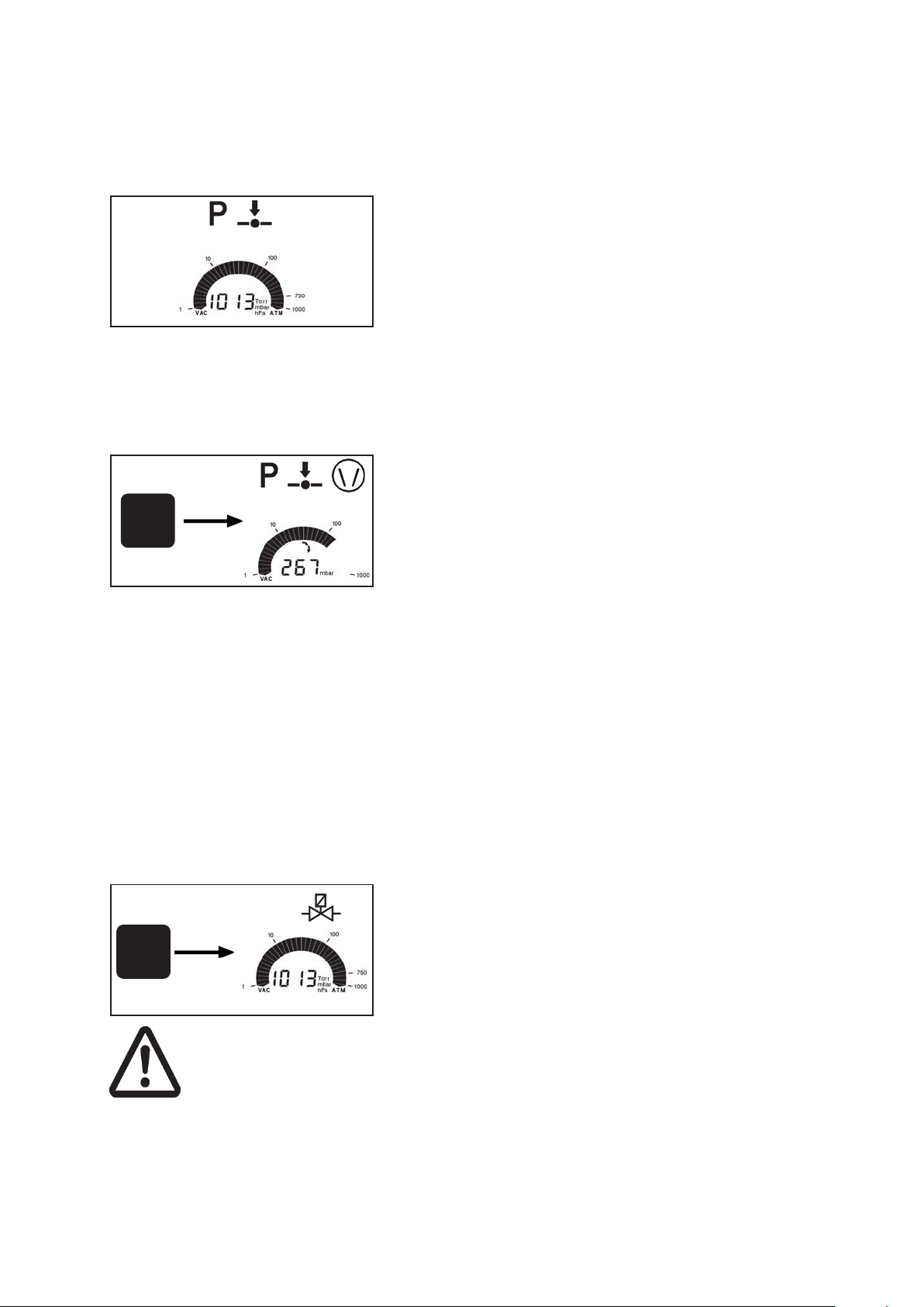
After switching on
The process control is not active, i. e. the controller is ready for
vacuum control, but control operation has not been started.
☞ The mode as from last operation is reactivated (after first
switching on “vacuum control” (factory-set) is displayed).
☞ The actual pressure is displayed.
☞ Values as from last operation are reactivated.
☞ Press key START/STOP to start process control.
☞ A coolant valve has to be preselected, see section ” Setting
the mode”.
Starting and stopping the process control
➨ Starting process control: Press key START/STOP.
☞ If a coolant valve is preselected: Coolant valve opens im-
START
STOP
mediately, the symbol is displayed.
➨ Stopping process control: Press key START/STOP.
☞ The pump is switched off.
☞ Attention: Adopt suitable measures if there is a possible pres-
sure increase after switching off the pump, e. g. due to low
boiling solvents.
☞ If a coolant valve is preselected: The coolant valve continu-
ous to run for additional 5 minutes to allow condensation of
vapours which remain in the system. Symbol “coolant” is
flashing.
Venting
(only possible if an external venting valve is connected and configurated)
Short venting, e. g. in case of boiling retardation or if sudden
foaming occurs:
➨ Press key VENT shortly (< 2 sec.).
VENT
Attention: If pressurized
inert gas is used install an
overpressure relief valve.
Ensure that high pressure
is compatible with the
mechanical stability of the
system!
Documents are only to be used and distributed completely and unchanged. It is strictly the users´ responsibility to check
carefully the validity of this document with respect to his product. manual-no.: 999100 / 06/05/2008
☞ Pumping is interrupted, the process control is stopped.
Venting the system:
➨ Press key VENT continuously (> 2 sec.) until symbol vent-
ing valve is flushing.
☞ Pumping is interrupted, the process control is stopped.
☞ Ventilation until pressure does not change any more, i. e.
until atmospheric pressure is attained.
☞ Key STOP interrupts venting at any time.
Page 22
page 22 of 49
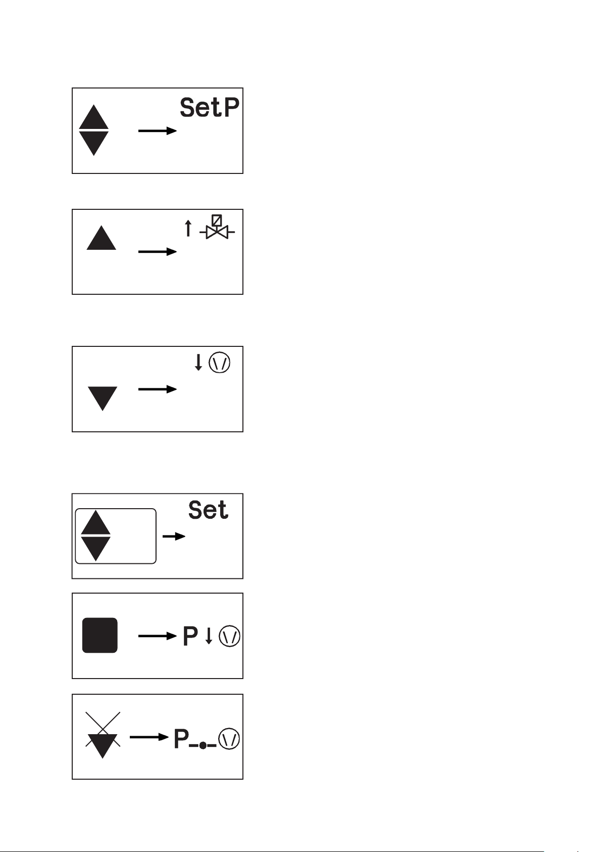
Setting of set point p (e. g. boiling point)
➨ Setting the set point by using the keys p▲ or p▼ (factory
set 100 mbar):
☞ To activate set mode: Press key shortly. “Set p“ appears.
☞ Short tips toggle p in steps of 1 mbar
p
267 mbar
☞ Continuous pressing activates ramp: Set-point changes with
increasing speed.
Adjusting of set point p during vacuum control
Adjusting the process pressure upwards
➨ Press key p▲.
☞ When the key is pressed shortly, the current pressure is
displayed for one second.
p
520mbar
p
67mbar
☞ With a second tip within one second or continuous pressing:
The venting valve is opened if connected or pressure in-
crease due to system parameters, the current pressure is
displayed.
☞ The achieved pressure is stored as new set point when the
key is released and adjusted automatically (only in auto-
matic mode).
Adjusting the process pressure by pumping down:
➨ Press key p▼.
☞ When the key is pressed shortly, the current pressure is
displayed for one second.
☞ With a second tip within one second or continuous pressing:
Pumping down with preset speed, the actual pressure is dis-
played and stored as new set point p when the key is re-
leased.
☞ The achieved pressure is stored as new set point and ad-
justed automatically.
Manual determination of the set point p (e. g. boiling point)
➨ Setting the value for the speed by using key Mode ▲ or ▼
(factory-set: ”HI” = maximum motor speed).
☞ To activate set mode: Press key shortly. The current preset
speed is displayed for one second.
☞ With a second tip within one second or continuous pressing:
45.0
START
STOP
p
☞ Set speed. The new set point is stored when the key is re-
leased.
To start process control:
➨ Start: Press key START and immediately key p▼. Keep key
p▼ pressed. Pumping down starts with preselected speed.
☞ Supervise process permanently. When sufficient evapora-
tion appears, release key p▼.
☞ The actual pressure is stored as new set point.
☞ Vacuum control starts.
☞ If the automatic mode is activated additionally (key MODE)
the set point is adjusted automatically in case of change of
boiling point.
Documents are only to be used and distributed completely and unchanged. It is strictly the users´ responsibility to check
carefully the validity of this document with respect to his product. manual-no.: 999100 / 06/05/2008
Page 23
Automatic mode
MODE
MODE
10.0
page 23 of 49
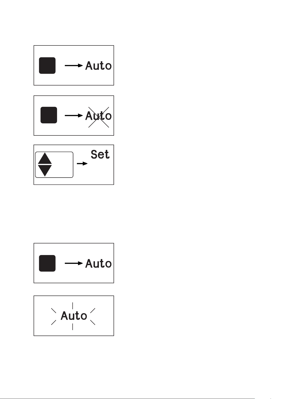
Additional switching on the automatic mode
➨ Press key MODE.
☞ “Auto” is displayed.
☞ After starting process control, the pressure is adapted to
the process automatically: The controller determines the pres-
sure and adapts if process parameters change.
☞ If automatic mode is switched on while vacuum control is
active, the process pressure is adapted.
Switching off the automatic mode
➨ Press key MODE.
☞ Switching off the automatic mode is possible at any time.
☞ “Auto” disappears.
☞ While vacuum control is active the actual pressure is stored
as new set point.
Setting the maximum speed:
Setting the value for the speed by using key Mode ▲ or ▼:
☞ To activate set mode: Press key shortly. The current speed
is displayed for one second.
☞ With a second tip within one second or continuous pressing:
☞ Set speed. The new set point is stored when the key is re-
leased.
☞ The reduced maximum speed restricts the evaporation rate
in case of low boiling solvents and a carry over of sub-
stances.
☞ The utilisation of a condenser or a cold trap at the inlet can
be optimized.
☞ If selecting ”HI” (recommended) for motor speed the maxi-
mum speed for automatic adaption of the motor speed is
restricted to a value corresponding to the system size.
To use the advantages of the automatic mode optimal, switch
on ”Auto” before starting the process.
☞ Switching on automatic mode: Press key MODE.
MODE
Documents are only to be used and distributed completely and unchanged. It is strictly the users´ responsibility to check
carefully the validity of this document with respect to his product. manual-no.: 999100 / 06/05/2008
☞ The controller determines the operating pressure.
☞ When activating the automatic mode if process control is
active (after pressing key START) the actual pressure is
stored as new boiling point and adjusted automatically.
If automatic switching off is preselected and the has controller determined that evaporation is completely finished:
☞ “Auto“ is flashing.
☞ The pump is switched off. If the controller measures a pres-
sure > 1060 mbar, the pressure is reduced to 1060 mbar to
avoid overpressure.
☞ The controller is still active, the control must be stopped by
pressing key STOP or by venting (the coolant valve will not
be closed until then).
Page 24
Automatic switching off
MODE
30mbar
page 24 of 49
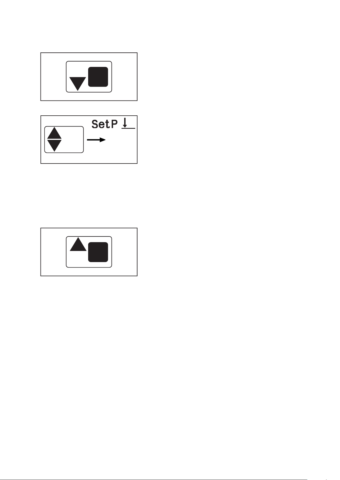
To chose a pressure value for automatic switching off is
only possible if automatic switching off is activated (in mode
vacuum control with automatic).
➨ Press key MODE simultaneous with ▼ (arrow down).
☞ When the key is pressed shortly, the current pressure for
automatic switching off is displayed for one second (”AE”, i.
e. automatic switching off is preselected at the factory). With
a second tip within one second or continuous pressing:
➨ Select pressure for automatic switching off by using keys ▲
or ▼ (pressure selectable in a range from 1 to 1060 mbar or
”AE”; ”AE”, i. e. automatic switching off is active if a pres-
sure value < 1mbar is selected).
☞ The pressure is stored as new pressure for automatic switch-
ing off when the key is released.
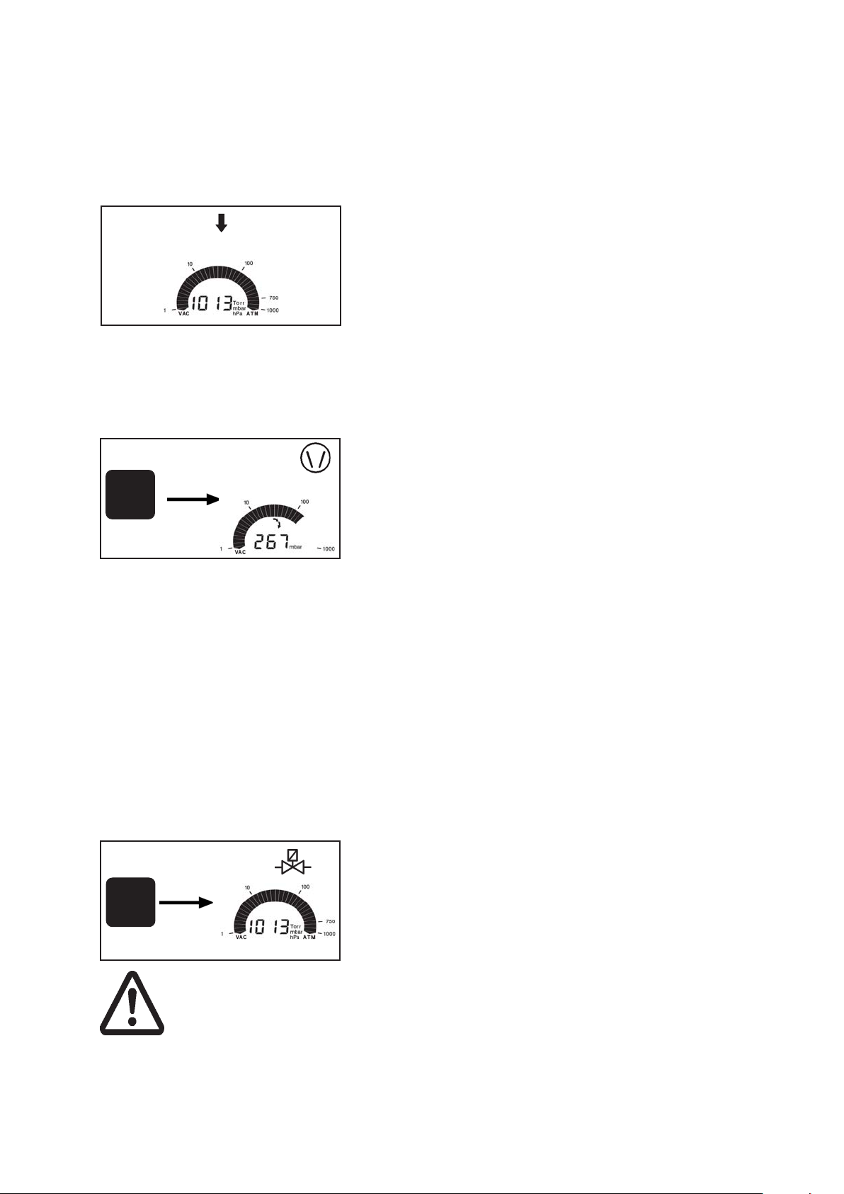
Changing to mode continuous pumping
➨ Press key MODE simultaneous with ▲ (arrow up).
☞ Switching to continuous pumping is only possible, if vacuum
control is not activated (after pressing key STOP).
MODE
☞ Adjust the pumping speed choosing an appropriate speed.
➨ Press key MODE again to switch to vacuum control.
☞ Switching to vacuum control is only possible, if pumping
down is activated (after pressing key START).
Documents are only to be used and distributed completely and unchanged. It is strictly the users´ responsibility to check
carefully the validity of this document with respect to his product. manual-no.: 999100 / 06/05/2008
Page 25
page 25 of 49
Mode continuous pumping
After switching on
The process control is not active, i. e. the controller is ready for
vacuum control, but control operation has not been started.
☞ The mode as from last operation is reactivated (after first
switching on “vacuum control” (factory-set) is displayed).
☞ The actual pressure is displayed.
☞ Values as from last operation are reactivated.
☞ Press key START/STOP to start process control.
☞ A coolant valve has to be preselected, see section ” Setting
the mode”.
Starting and stopping the process control
➨ Starting process control: Press key START/STOP.
☞ If a coolant valve is preselected: Coolant valve opens im-
START
STOP
mediately, the symbol is displayed.
➨ Stopping process control: Press key START/STOP.
☞ The pump is switched off.
☞ Attention: Adopt suitable measures if there is a possible pres-
sure increase after switching off the pump, e. g. due to low
boiling solvents.
☞ If a coolant valve is preselected: The coolant valve continu-
ous to run for additional 5 minutes to allow condensation of
vapours which remain in the system. Symbol “coolant” is
flashing.
Venting
(only possible if an external venting valve is connected and configurated)
Short venting, e.g. in case of radiation of boiling or sudden
foaming occurs:
➨ Press key VENT shortly (< 2 sec.).
VENT
Attention: If pressurized
inert gas is used install an
overpressure relief valve.
Ensure that high pressure
is compatible with the
mechanical stability of the
system!
Documents are only to be used and distributed completely and unchanged. It is strictly the users´ responsibility to check
carefully the validity of this document with respect to his product. manual-no.: 999100 / 06/05/2008
☞ Pumping is interrupted, the process control is stopped.
Venting the system:
➨ Press key VENT continuously (> 2 sec.) until symbol vent-
ing valve is flashing.
☞ Pumping is interrupted, the process control is stopped.
☞ Ventilation until pressure does not change any more, i. e.
until atmospheric pressure is attained.
☞ Key STOP interrupts venting at any time.
Page 26
Setting the pumping speed
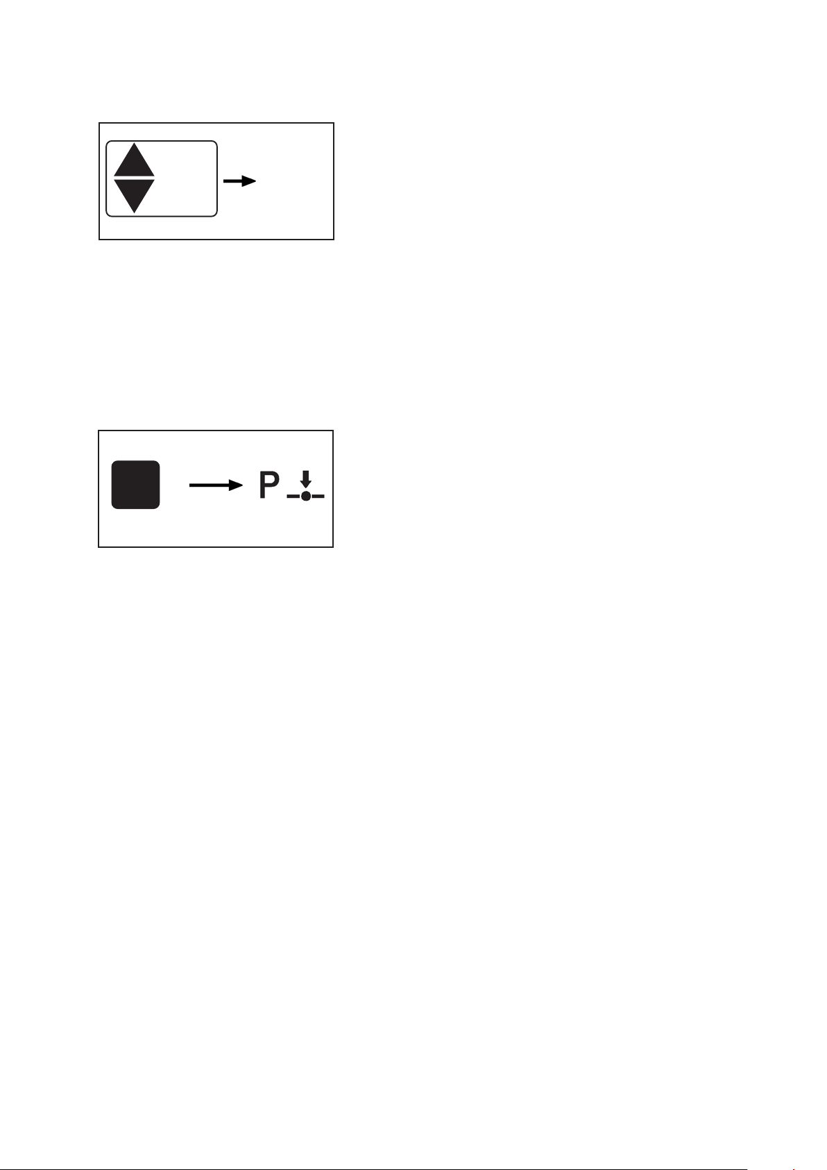
Setting of speed:
Setting the value for the speed by using key Mode ▲ or ▼:
☞ To activate set mode: Press key shortly. The current speed
45.0
☞ With a second tip within one second or continuous pressing:
☞ Set speed. The new set point is stored when the key is re-
☞ The maximum speed restricts the evaporation rate in case
☞ Setting the motor speed ”HI” (above 60 Hz) enables fast-
Changing to mode vacuum control
➨ Press key MODE.
☞ Switching to vacuum control is only possible, if pumping
MODE
☞ The actual pressure is stored as new set point, i.e. the con-
☞ Press key MODE again to activate automatic mode.
page 26 of 49
is displayed for one second.
leased.
of low boiling solvents and a carry over of substances.
est pumping down to the best ultimate vacuum.
down is activated (after pressing key START).
troller keeps the pressure constant.
Documents are only to be used and distributed completely and unchanged. It is strictly the users´ responsibility to check
carefully the validity of this document with respect to his product. manual-no.: 999100 / 06/05/2008
Page 27
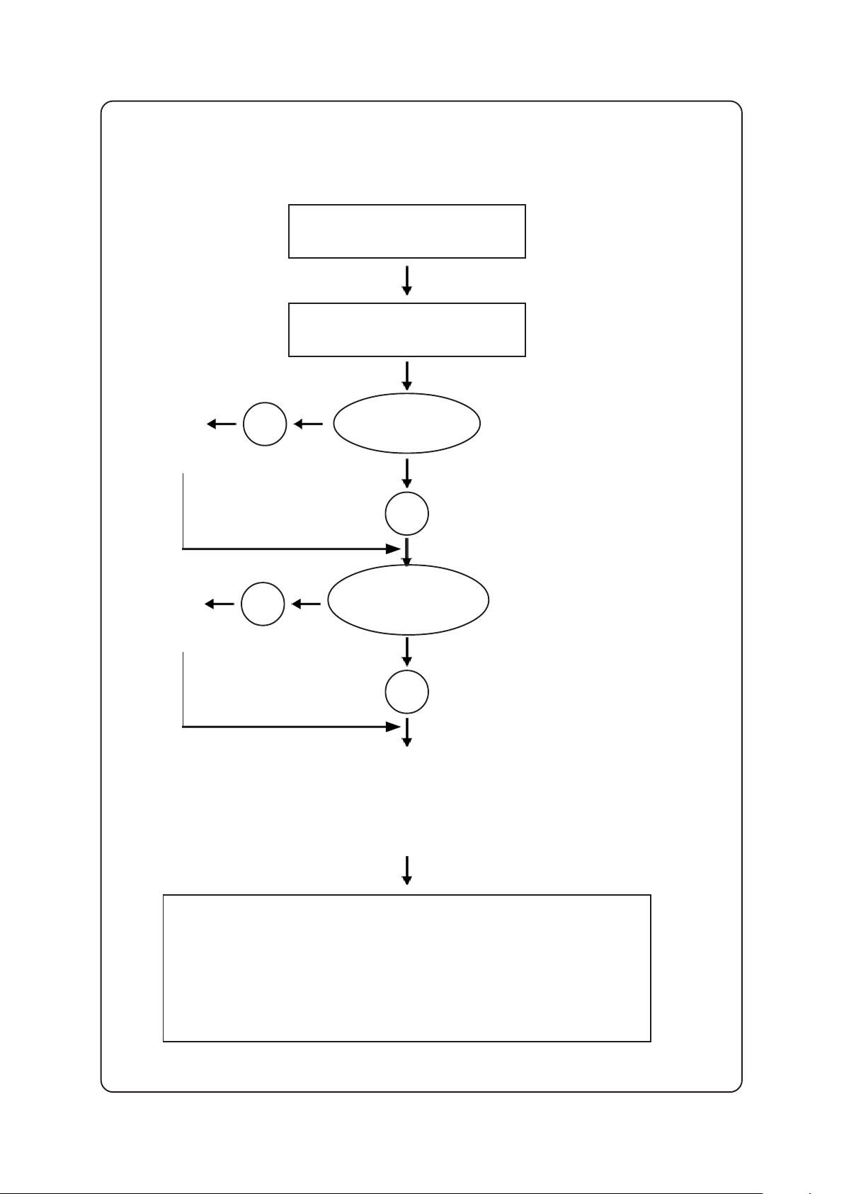
page 27 of 49
General view mode VACUU•LAN
setting the mode
mode VACUU•LAN
connect and
configurate
coolant
valve
connect and
configurate
venting valve
yes
yes
switching coolant
valve?
no
switching
venting
valve?
no
setting process parameters
➨ lower pressure value (condition for automatic shut down)
➨ upper pressure value (condition for restart)
➨ time for automatic shut down
start: pump down
☞☞
☞ The pump (and the coolant valve if applicable) is switched
☞☞
off if the pressure is below the lower pressure value
longer than the time for automatic shut down.
☞☞
☞ The pump starts automatically if the pressure is higher
☞☞
than the upper set point or great pressure increase.
Documents are only to be used and distributed completely and unchanged. It is strictly the users´ responsibility to check
carefully the validity of this document with respect to his product. manual-no.: 999100 / 06/05/2008
Page 28
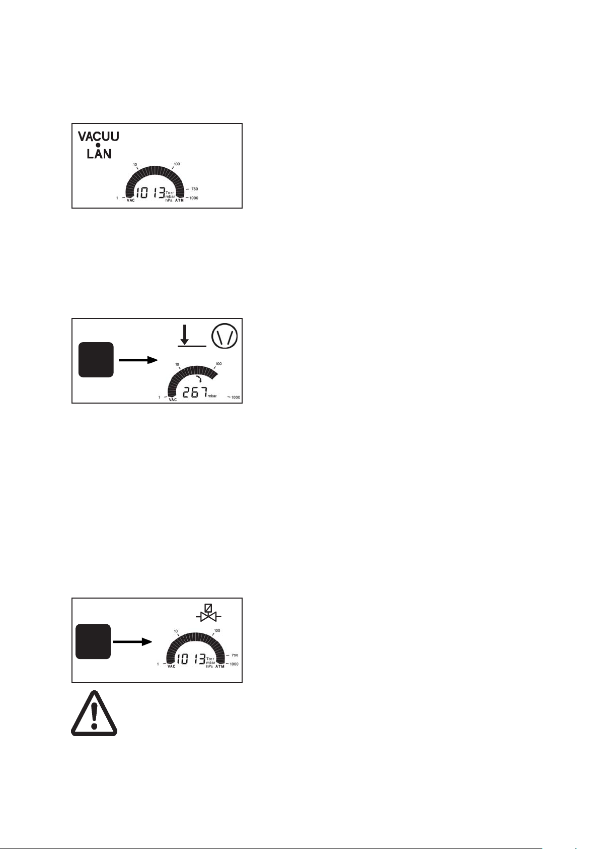
page 28 of 49
Mode VACUU•LAN
After switching on
The process control is not active, i. e. the controller is ready for
vacuum control, but control operation has not been started.
☞ The mode as from last operation is reactivated (after first
switching on “vacuum control” (factory-set) is displayed).
☞ The actual pressure is displayed.
☞ Values as from last operation are reactivated (factory-set:
time for automatic shut down 15 minutes, pressure value
(condition for switching off) 25 mbar, upper set point (condi-
tion for restart) 150 mbar).
☞ Press key START/STOP to start process control.
☞ A coolant valve has to be preselected, see section ” Setting
the mode”.
Starting and stopping the process control
➨ Starting process control: Press key START/STOP.
☞ The pump is switched on.
START
STOP
☞ If a coolant valve is preselected: Coolant valve opens im-
mediately, the symbol is displayed.
☞ If the pressure for switching off is achieved, the motor speed
gets reduced.
☞ The pump (and the coolant valve if applicable) is switched
off if the pressure is below the lower pressure value longer
than the time for automatic shut down.
☞ The pump starts automatically if the pressure is higher than
the upper pressure value and in case of sudden gas forma-
tion.
➨ Stopping: After pressing key START/STOP or venting the
process control stops.
☞ The pump is switched off.
☞ If a coolant valve is preselected: The coolant valve is
switched off.
Venting
(only possible if an external venting valve is connected and configurated)
Short venting, e. g. in case of radiation of boiling or sudden
foaming occurs:
➨ Press key VENT shortly (< 2 sec.).
VENT
Attention: If pressurized
inert gas is used install an
overpressure relief valve.
Ensure that high pressure
is compatible with the
mechanical stability of the
system!
Documents are only to be used and distributed completely and unchanged. It is strictly the users´ responsibility to check
carefully the validity of this document with respect to his product. manual-no.: 999100 / 06/05/2008
☞ Pumping is interrupted, the process control is stopped.
Venting the system:
➨ Press key VENT continuously (> 2 sec.) until symbol vent-
ing valve is flushing.
☞ Pumping is interrupted, the process control is stopped.
☞ Ventilation until pressure does not change any more, i. e.
until atmospheric pressure is attained.
☞ Key STOP interrupts venting at any time.
Page 29
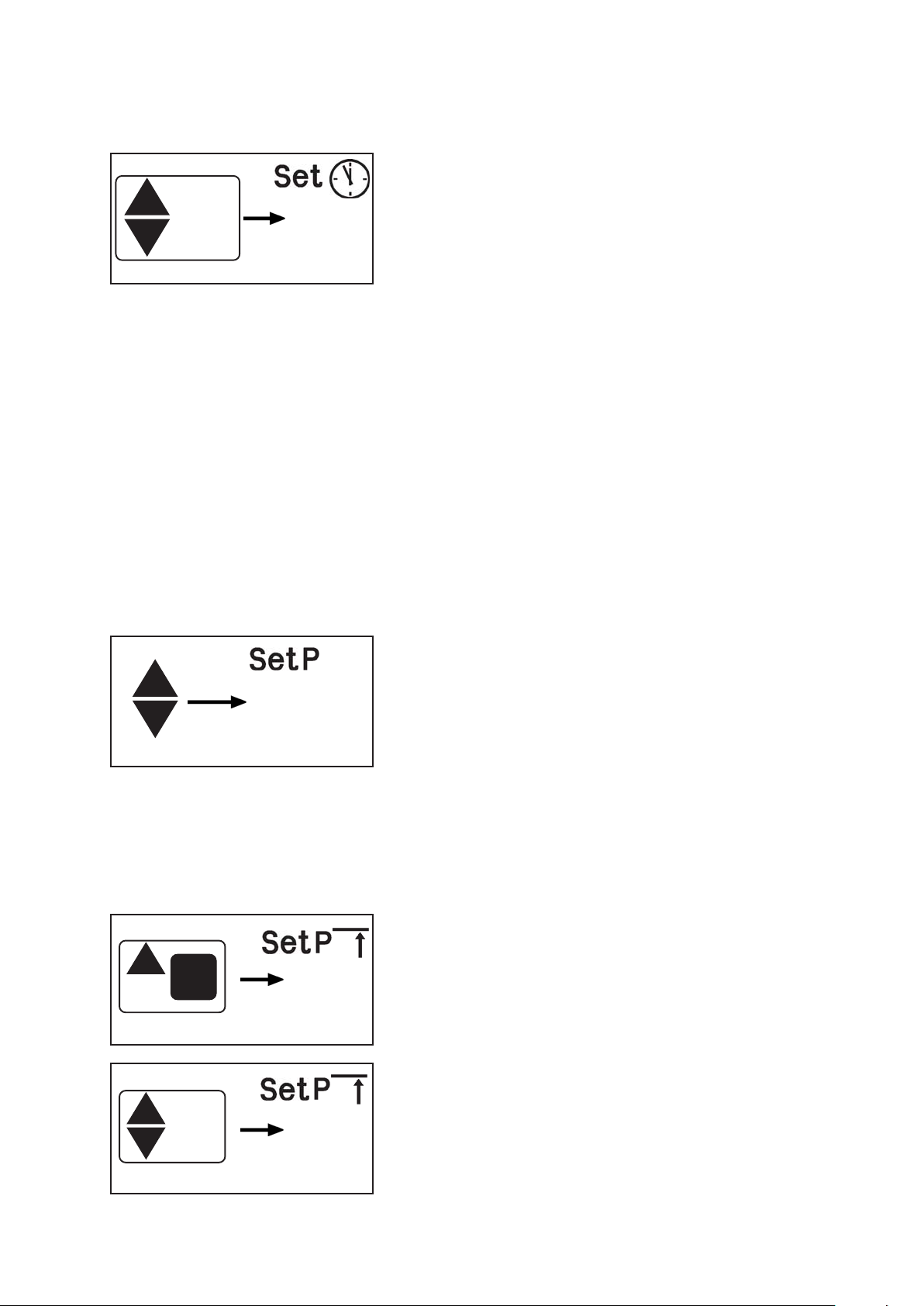
Setting the process parameter
015
page 29 of 49
Setting the time for automatic shut down:
➨ Press key Mode ▲ or ▼.
☞ Set and the clock symbol and the time for automatic shut
down are displayed for approx. 1 s.
☞ With a second tip within one second or continuous pressing:
➨ Press key Mode ▲ or ▼ to set value for time for shut down
(1 - 200 min).
☞ The value for the shut down time is stored as the new set
point when the key is released.
☞ If the actual pressure is below the lower set point, the time
for automatic shut down is running. Reset of the time for
automatic shut down if the actual pressure is higher than the
lower set point (with a hysteresis of 3 mbar).
The process control stops when the time for shut down has
passed. The vacuum pump and the coolant valve switch off.
☞ Pump starts again in case of great pressure increase.
☞ If the actual pressure is higher than the upper set point, the
pump starts again (corresponds to starting by pressing key
START).
☞ The process control can be manually stopped at any time
by pressing key STOP.
Setting the lower pressure value (condition for automatic
switching off):
➨ Press p▲ or p▼.
☞ Set p and the lower pressure value are displayed for approx.
p
MODE
67mbar
1s.
☞ With a second tip within one second or continuous pressing:
➨ Set the lower pressure value by pressing key p▲ or p▼.
☞ The lower pressure value is stored as the new set point when
the key is released.
Note: It is recommended to select a pressure value which is
approx. 10 mbar higher than the ultimate pressure value achievable in the system.
Setting the upper pressure value (condition for restart):
➨ While key MODE is pressed, press key Mode and ▲ .
☞ Set p, arrow up and the upper pressure value are displayed
for approx. one second.
67mbar
☞ With a second tip within one second or continuous pressing:
➨ Set the upper pressure value by pressing key Mode ▲ or ▼.
☞ The upper pressure value is stored as the new set point
when the key is released.
247mbar
Documents are only to be used and distributed completely and unchanged. It is strictly the users´ responsibility to check
carefully the validity of this document with respect to his product. manual-no.: 999100 / 06/05/2008
Page 30
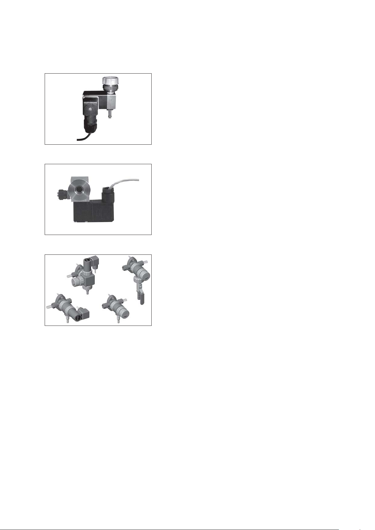
Accessories
Coolant minimization
Venting
page 30 of 49
Coolant valve 24 V= ................................................... 676013
- compact design, designed for a high number of operations
at short intervals
- solenoid systems with splash protection
- conductance optimized for applications with rotary evapora-
tor and exhaust waste vapour condenser
Venting valve VB M2 24 V= ....................................... 666817
Vacuum distribution
VCL 11
VCL 10
VCL 02
VCL 01
The VACUU•LAN® modules allow process orientated, flexible
and cost effective connections according to the requirements:
One vacuum pump for multiple work stations.
VACUU•LAN® manual flow control module
VCL 01 ........................................................................ 677106
VACUU•LAN® shut off-/ manual flow control
module VCL 02 ......................................................... 677107
VACUU•LAN® automatic control module
VCL 10 ........................................................................ 677108
VACUU•LAN® manual flow control/automatic
control module VCL 11 ............................................ 677109
On this page we offer only a small selection of VACUU•LAN® options. Please refer for further information.
Documents are only to be used and distributed completely and unchanged. It is strictly the users´ responsibility to check
carefully the validity of this document with respect to his product. manual-no.: 999100 / 06/05/2008
Page 31
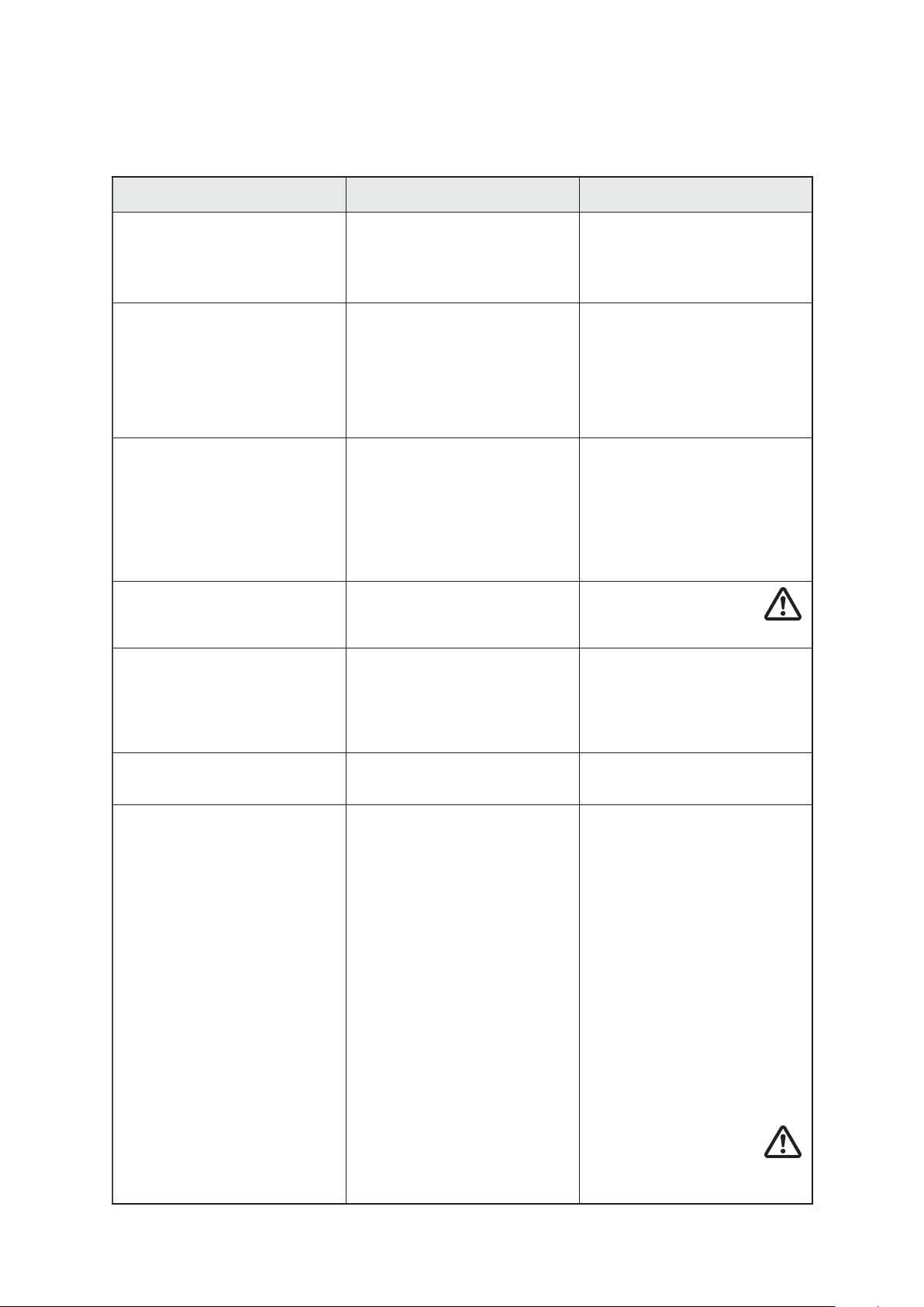
Troubleshooting
☞☞
☞ Read the instructions for use.
☞☞
tluaF esuacelbissoP ydemeR
page 31 of 49
.yalpsidoN
,sraeppasidyalpsiD
.detautcasemoceb
signidaererusserP
.tcerrocni
yalpsiderusserplatigiD
.gnihsalf
rotacidninoitcnuflaM
recudsnarterusserp
dnaelgnairtgninraw(
.)"rrE"
.noitcnuftuohtiw
.gnihsalferalobmys
Î
Î
Î
noitcetorpdaolrevolanretni
Î
Î
Î
Î
Î
Î
eraelgnairtgninrawdna
Î
Î
Î
syeklla,deyalpsidsi"CP"
Î
pmupdnaelgnairtgninraW
Î
Î
Î
Î
Î
?)evitcefed
?hgih
?)evitcefed
?recudsnart
?recudsnart
?detcennoc
?evitcefed
?enilepip
?pmupehtfo
?nideggulptonsniaM
ecived(esuacrehtO
si,daolrevolamrehT
ehttatiucrictrohS
?sevlavdetcennoc
ecived(esuacrehtO
ehttaerusserprevO
,recudsnarterusserp
!rabm0011>erusserp
tondaeheguaG
recudsnarterusserP
etomernisirellortnoC
?)ecafretniehtaiv
?scinortcelepmuptluaF
rewopdnaenillortnoC
pmupehtotylppus
?dedaolrevorotoM
ehttaerusserprevO
ruopavetsawtsuahxe
)
.gnidliubeht
)
)
ooterutarepmettneibma
)
)
)
?ffodetfirdsahtnemtsujdA
)
erusserpehtnierutsioM
)
erusserpehtnostisopeD
)
)
)
)
dellortnocylno(noitarepo
)
)
?detcennoctonscinortcele
)
)
teltuoehtniroresnednoc
)
?llamsootylppusrewoP
)
edacolbroevitcefedrotoM
.etauqeda
.rellortnoc
.ecived
.riaperrofyrotcaf
.sevlavecalpeR
.riaperrofyrotcaf
.yrassecen
etomerffohctiwS
.yrassecen
.scinortcele
hctiws,gulpsniamtresnI
niesufsniamkcehC.no
ehtotecivedehtnruteR
sinoitalitneverusekaM
ehtotecivedehtnruteR
.ecivedehttsujdaeR
gnipmupyb.g.e,yrD
esu,tsujdaer,recudsnart
fielttobgnihsawsag
.ecnanetniamnoitceseeS
yletaidemmieveileR
erusserp(erusserp
reffusyamrecudsnart
.gnitsrubfoksiR.)egamad
ehtotdaeheguagtcennoC
ehttarotcennocelamef
.daeheguagwenesU
ees,esacninoitarepo
."ecafretni"noitces
eruliaffoesuacyfitnedI
sutatseruliafehtfoteser(
ybelbissopylnosi
,rellortnocehtffognihctiws
.s06tiawtratsererofeb
firotubirtsidlacoltcatnoC
ehtfonoitallatsnikcehC
rewopdnaenillortnoc
pmupehtotylppus
loocotrotomehtwollA
foesuacyfitnedi,nwod
ehttesernehT.eruliaf
.ffognihctiwsybrellortnoc
ekam,enilepipteltuonepO
tsuahxeehttahterus
siresnednocruopavetsaw
kcehc,dekcolbton
feilerytefaserusserprevo
.ylppusrewopkcehC
.rotubirtsidlacoltcatnoC
Documents are only to be used and distributed completely and unchanged. It is strictly the users´ responsibility to check
carefully the validity of this document with respect to his product. manual-no.: 999100 / 06/05/2008
Page 32

page 32 of 49
tluaF esuacelbissoP ydemeR
tcaertonseodrellortnoC
)
.rotubirtsidlacoltcatnoC
oN.syekgnitareponehw
.no/ffohctiwsretfaegnahc
Î
.yletaidemmi
spotsrotratsotsliafpmuP
?etasnednocot
)
desopxeneebsahpmuP
htiwnurotpmupehtwollA
emosrofnepotroptelni
.deeps.xamtasetunim
eveihcatonseodpmuP
Î
lamronromuucavetamitlu
?rellortnoc
ehttasgnittestcerrocnI
.deepsgnipmup
)
edomnoitarepoesoohC
ahtiwgnipmupsuounitnoc
dnazH06foycneuqerf
.niagakcehc
Î
Î
ehtnikaelrodenoitisop
muucavroenilepip
?metsys
?enilworran,gnoL
)
yltcerroctongnirgnirtneC
ahtiwpmupkcehC
tayltcerideguagmuucav
kcehc,troptelnipmup
.senildnasnoitcennoc
)
regralhtiwenilesU
trohssahtgnel,retemaid
.elbissopsa
Î
?etasnednocot
)
desopxeneebsahpmuP
htiwnurotpmupehtwollA
emosrofnepotroptelni
deeps.xamtasetunim
.)"IH"(
Î
Î
Î
neebevahstisopeD
sevlavrosmgarhpaiD
?evitcefed
ehtnidetarenegruopav
)
?pmupehtedisnidemrof
.sdaeh
)
pmuptcepsnidnanaelC
smgarhpaidecalpeR
.sevlavro/dna
)
rosecnatsbusgnisagtuO
ssecorpkcehC
.sretemarap
?ssecorp
Î
?tohootpmuP
)
loocotpmupehtwollA
foesuacyfitnedi,nwod
.etanimilednagnitaehrevo
Î
citamotuaroferusserP
?deveihcaffognihctiws
)
roferusserpegnahC
fiffognihctiwscitamotua
.yrassecen
.ysionootpmuP
Î
hgihrocirehpsomtA
)
?troptelniehttaerusserp
.teltuo
pmupotesohtcennoC
Î
)
csidgnipmalcmgarhpaiD
.ecnanetniammrofreP
?esool
Î
)
denoitnemevobafoenoN
.rotubirtsidlacoltcatnoC
?sesuac
Documents are only to be used and distributed completely and unchanged. It is strictly the users´ responsibility to check
carefully the validity of this document with respect to his product. manual-no.: 999100 / 06/05/2008
.deziespmuP
)
.rotubirtsidlacoltcatnoC
Page 33

page 33 of 49
Readjustment
The vacuum gauge was adjusted using factory standards, which are traceable through
regular calibration in an accredited laboratory (German Calibration service) to the national standard. Depending on the process and/or accuracy requirements, check the
adjustment and readjust if necessary. For readjustment, the device has to be adjusted
both at atmospheric pressure as well as under vacuum.
The adjustment mode can be activated only if the process control is inactive. Press
key STOP if necessary.
Adjustment at atmospheric pressure
Ventilate the controller and/or the vacuum system. Make sure
that the vacuum connection at the controller is at atmospheric
pressure.
MODE
+
p
Note: To determine the actual atmospheric pressure, use an accurate barometer or get accurate reading
from the weather service, the next airport.......(take into account the difference in altitude between e. g.
airport and laboratory).
CAL
Adjustment under vacuum
MODE
+
p
Note: Adjustment under vacuum with an actual pressure higher than 0.5 mbar reduces the accuracy of the
measurement. If the pressure is significantly higher than 0.5 mbar, adjustment to a reference pressure is
recommended.
CAL
➨ Press key p▲ or p▼ simultaneously with key MODE, the
controller then switches to the adjustment mode.
☞ The warning triangle and CAL are displayed for approx. 2
seconds.
➨ While CAL is displayed, press key START/STOP.
➨ Use key p▲ or p▼ to adjust the reading to the actual at-
mospheric pressure.
➨ Press key STOP to confirm.
Evacuate the controller to a pressure < 0.5 mbar (e. g. by applying a good rotary vane pump).
➨ Press key p▲ or p▼ simultaneously with key MODE, the
controller then switches to the adjustment mode.
☞ The warning triangle and CAL are displayed for approx. 2
seconds.
➨ While CAL is displayed, press key START/STOP.
☞ The reading is automatically adjusted to ”zero”.
➨ Press key STOP to confirm.
Adjustment at a reference pressure
Instead of adjustment under vacuum to a pressure < 0.5 mbar,
adjustment to a reference pressure within the range of 0 ..... 20
mbar is possible.
MODE
+
p
CAL
0 .... 20 mbar
p
Note: The accuracy of the value of the reference pressure will directly affect the accuracy of the adjustment.
If the nominal ultimate vacuum of a diaphragm pump is used as reference vacuum, the accuracy of the
controller might be doubtful. The diaphragm pump may not achieve the specified value (due to condensate,
poor state, failure of valves or the diaphragm).
Documents are only to be used and distributed completely and unchanged. It is strictly the users´ responsibility to check
carefully the validity of this document with respect to his product. manual-no.: 999100 / 06/05/2008
➨ Press key p▲ or p▼ simultaneously with key MODE, the
controller then switches to the adjustment mode.
☞ The warning triangle and CAL are displayed for approx. 2
seconds.
➨ While CAL is displayed, press key START/STOP.
☞ The reading is automatically adjusted to ”zero”.
➨ Use keys p▲ or p▼ to adjust the display to the reference
pressure at the vacuum line within the range of 0 ..... 20
mbar.
➨ Press key STOP to confirm.
Page 34
page 34 of 49
How to determine the best distillation conditions
Determine the temperature of the available coolant.
☞ In most cases the coolant temperature is given (e. g. tap water, in house coolant circuit). For maximum
solvent recovery, carefully choose the boiling point of the product (by choosing the vacuum level) and
the bath temperature accordingly.
☞ Determine the lowest boiling point of the product (solvent).
☞ The temperature difference between boiling point of the product and the coolant should be more than
20°C, otherwise low vacuum level will lead to significant loss of solvent.
☞ Select a water bath temperature of 20-30°C above the boiling point of the product to provide sufficient
heat transfer.
Determine the temperature of the bath.
☞ If there is no limitation from the product side, a water bath temperature of 60-70°C is usually recom-
mended (efficient heating with minimum generation of water vapour from the bath).
Example: Vacuum selection for a boiling temperature of 40°C (e. g. ethanol):
☞ The cooling temperature assumed to be 15-20°C.
☞ Water bath temperature 40°C. Wait until temperature is reached.
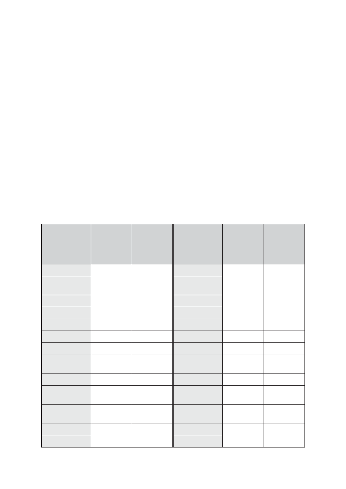
☞ Determine the vacuum level (for ethanol: 170 mbar) for a boiling point (use published data of solvents).
Reduce pressure until a sufficient level of evaporation is attained or use the mode ”AUTO” of the
controller (distillation fully automatically).
List of solvents
tnevloS gnilioB
enotecA65655 etatecalyhtE77042
elirtinotecA28032 -enelyhtE
enezneB08632 enaxeH96533
lonatuB-t28031 lonahteM46733
lonatuB-181152 enatneP630001>
mroforolhC26474 lonaporposI28731
enaxeholcyC18532 enidiryP51106
enahtemorolhciD040001 -orolhcarteT
rehtelyhteiD530001> enarufordyharteT66753
rofmuucaV
ta)C°(tniop
rabm3101
gniliob
)rabm(tniop
ta).sba(
T
C°04=
s
tnevloS gnilioB
rofmuucaV
ta)C°(tniop
rabm3101
gniliob
)rabm(tniop
ta).sba(
T
C°04=
s
38012
edirolhcid
77172
enahtem
lyporposiiD
86573 eneuloT11177
rehte
-lyhtemiD
35111 enelyhteorolhcirT78381
edimamrof
enaxoiD-4,1101701 enelyX83152
lonahtE87571 retaW00127
Documents are only to be used and distributed completely and unchanged. It is strictly the users´ responsibility to check
carefully the validity of this document with respect to his product. manual-no.: 999100 / 06/05/2008
Page 35
page 35 of 49
Interface parameters
The controller CVC 2000II is equipped with a serial interface at the rear side of the housing (RS 232C, ninepole Sub-D-plug).
☞ Respectively plug-into or remove the cable (cable RS 232C, nine-pole, Sub-D) from the interface only if
the equipment is switched off.
☞ The interface is not electrically isolated from the measuring circuit.
☞ For optimal electromagnetic compatibility assemble an interface filter (cat. no.: 638235).
The controller can be operated via serial interface. Measuring results, preselections and the status of the
controller can be read at any time. Controlling via interface is only possible, if the remote operation mode
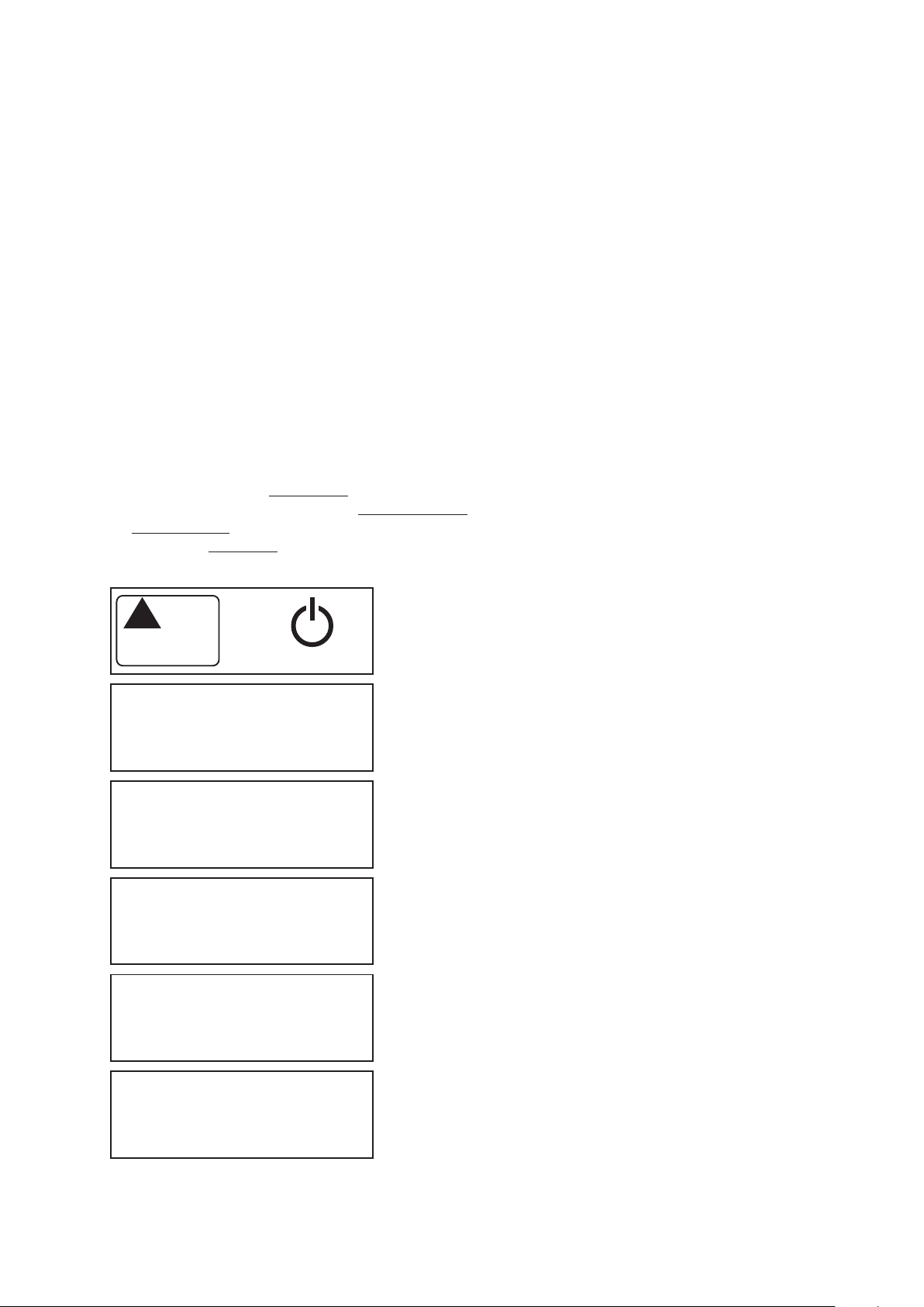
has been preselected at the controller. During remote operation (”PC” is displayed) the controller can
be operated only via interface, the keys at the controller have no function, the warning triangle is
displayed.
Setting of the interface
Setting of the interface parameters directly at the controller is described below. The factory set values are
underlined.
➨ 1200, 2400, 4800 or 9600 BAUD
➨ 7 data bits odd, 7 data bits even, 8 data bits none, 8 data bits odd, 8 data bits even
➨ no Handshake, XON/XOFF Handshake, CTS/RTS Handshake
➨ remote on, remote off
☞ Unchangeable: Startbit = 1, Stopbit = 1
Set
Set
Set
Set
+
b.96
d. 8
P.no
h.no
Press key Mode ▲ during switching-on.
☞ The controller switches to the mode to configurate the inter-
face.
(mains switch)
BAUD-Rate is displayed.
➨ Press key Mode ▲ or ▼ to select the BAUD rate and con-
firm with key STOP (”96”=9600, ”48”=4800, ”24”=2400,
”12”=1200).
Data bits are displayed.
➨ Press key Mode ▲ or ▼ to select the data bits and confirm
with key STOP.
Parity is displayed.
➨ Press key Mode ▲ or ▼ to select parity and confirm with
key STOP (”no” = no check of parity, ”O” = odd, ”E” = even).
Handshake is displayed.
➨ Press key Mode ▲ or ▼ to select handshake and confirm
with key STOP (”no” = no Handshake, ”HA” = RTS/CTS,
”SO” = XON/XOFF).
Remote is displayed.
Set
r.no
Documents are only to be used and distributed completely and unchanged. It is strictly the users´ responsibility to check
carefully the validity of this document with respect to his product. manual-no.: 999100 / 06/05/2008
➨ Press key Mode ▲ or ▼ to select parity and confirm with
key STOP (”no” = local operation, ”On” = remote operation).
☞ The controller switches to normal operation mode (process
control not active).
Page 36

page 36 of 49
Read commands
Function Command Response Description
actual pressure IN_PV_1 XXXX mbar or unit according to preselections
XXXX Torr or
XXXX hPa
actual frequency IN_PV_2 XX.X Hz
device set IN_CFG XXXXX
preselections
0: remote operation off
1: remote operation on
0: no automatic switch off
1: automatic switch off
0: no venting valve
1: venting valve
0: no coolant valve
1: coolant valve
0: VACUU•LAN
1: continuous pumping
2: vacuum control without automatic
3: vacuum control with automatic
malfunction IN_ERR XXXX
1: last command to interface incorrect
1: malfunction pressure transducer
1: overpressure
1: fault pump electronics
status of IN_STAT XXXX
process control 00: VACUU•LAN: inactive
01: pumping down, actual pressure
> selected pressure
02: pumping down, time for automatic
switching off is running
03: system is switched off
10: continuous pumping: inactive
11: active
20: vacuum control: inactive
21: actual pressure
> selected pressure
22: actual pressure =
selected pressure (+/- 1mbar)
23: actual pressure
< selected pressure
30: automatic: inactive
31: determining boiling point
32: adjusting boiling point
33: system is switched off
0: venting valve not driven (closed)
1: venting valve driven (open)
0: coolant valve not driven (closed)
1: coolant valve driven (open)
Documents are only to be used and distributed completely and unchanged. It is strictly the users´ responsibility to check
carefully the validity of this document with respect to his product. manual-no.: 999100 / 06/05/2008
Page 37

page 37 of 49
Write commands
Function Command Parameter Description
selected pressure OUT_SP_1 XXXX unit according to preselection
(0001 to 1060 mbar (hPa) or 0001 to 0795 Torr)
selected pressure OUT_SP_V XXXX unit according to preselection
with venting* (0001 to 1060 mbar (hPa) or 0001 to 0795 Torr)
selected frequency OUT_SP_2 XX.X Hz (01.0 to 60.0 in steps of 0.5 Hz or 99.9 for “HI”)
pressure for restart OUT_SP_3 XXXX unit according to preselection
(VACUU•LAN) (see OUT_SP_1)
time for automatic OUT_SP_4 XX:XX hours:minutes
switching off (VACUU•LAN)
automatic switching off OUT_SP_5 XXXX unit according to preselection
(vacuum control) (see OUT_SP_1) or ”0000” for automatic
switching off (“AE”)
operation mode OUT_MODE X 1: continuous pumping
2: vacuum control without automatic
3: vacuum control with automatic
driving venting OUT_VENT X 0: venting valve closed (not automatically)
valve 1: venting valve open (process control
stopped)
starting process control START
stopping process control STOP X 1: termination of process control
2: termination of process control and storage of
the actual pressure as new set point
Remote operation** REMOTE X 0: set controller to local operation
1: set controller to remote operation
* Pressure setting with venting is only possible in operation mode ”Vacuum control” if an venting valve is
connected and configurated and Vacuum control is started. The venting valve opens automatically if the
actual pressure is 10 mbar below the preset pressure. Automatic venting becomes inactive if Vacuum
control is stopped (STOP or VENT), setting a pressure value using the command OUT_SP_1 or if the
operation mode is changed. Activate the command OUT_SP_V again if necessary.
** If remote operation is selected or deselected, the user has to ensure that no dangerous status of the
system due to the change of the mode of operation can occur and to provide appropriate safety measures, especially if selecting remote operation interferes with a locally operated active process.
The single abbreviations of a command are separated by underscores (ASCII 5FH).
Command and parameter are separated by ignore characters (ASCII 20H).
The string is terminated with <CR><LF> (ASCII 0DH, ASCII 0AH).
Set the values with leading zeros if necessary.
Connector assignment
2: RxD 5: Mass
3: TxD 7: RTS
4: DTR 8: CTS
Documents are only to be used and distributed completely and unchanged. It is strictly the users´ responsibility to check
carefully the validity of this document with respect to his product. manual-no.: 999100 / 06/05/2008
Page 38
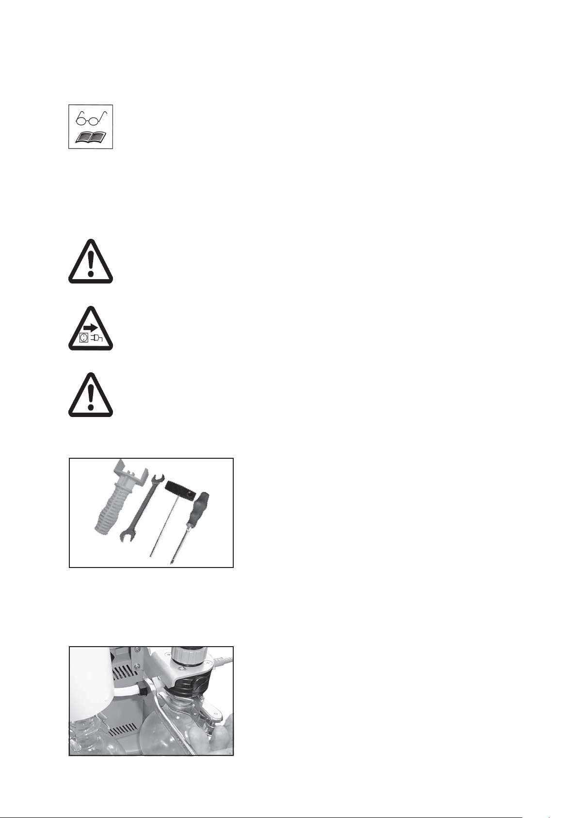
page 38 of 49
Replacing diaphragms and valves
All bearings are encapsulated and are filled with long-life lubricant. Under normal operating conditions, the pump is maintenance free. The valves and the diaphragms are
wear parts. If the rated ultimate vacuum is no longer achieved or in case of increased
noise level, the pump interior, the diaphragms and the valves must be cleaned and the
diaphragms and valves must be checked for cracks or other damage. Depending on
individual cases it may be efficient to check and clean the pump heads on a regular
basis. In case of normal wear the lifetime of the diaphragms and valves is > 10000
operating hours.
☞ Prevent internal condensation, transfer of liquids or dust. The diaphragm and valves
will be damaged, if liquids are pumped in significant amount.
If the pump is exposed to corrosive gases or vapour or in case of deposits, maintenance should be carried out frequently.
☞ Regular maintenance will improve the lifetime of the pump and also protect both
personnel and environment.
Before starting maintenance vent the system, isolate the pump and other components from the vacuum system and the electrical supply. Wait two minutes after iso-
lating the equipment from mains to allow the capacitors to discharge. Drain condensate
if applicable, avoid the release of pollutants. Allow sufficient cooling of the pump. En-
sure that the pump cannot be operated accidentally. Never operate the pump if
covers or other parts of the pump are disassembled. Never operate a defective or
damaged pump.
Ensure that the maintenance technician is familiar with the safety procedures which
relate to the products processed by the pumping system.
Attention: The pump might be contaminated with the process chemicals that have
been pumped during operation. Ensure that the pump is decontaminated before maintenance and take adequate precautions to protect people from the effects of dangerous substances if contamination has occurred.
☞ Wear appropriate safety-clothing when coming in contact with contaminated com-
ponents.
Set of seals MD 1C (4 diaphragms, 8 valves, diaphragm key) .......................................... cat. no. 696828
Tools:
- diaphragm key w/f 46
- open ended wrench w/f 15 / 17
- hex key size 4/5
- Phillips screw driver size 2
☞☞
☞ Please read section ”Replacing diaphragms and valves” completely before start-
☞☞
ing maintenance.
Partially the pictures show pumps in other versions. This doesn´t influence replacing diaphragms and
valves of the pump.
Cleaning and inspecting the pump heads:
Use open-ended wrench to remove union nut at the inlet of the
pump.
Remove hose from the fitting.
Do not remove the elbow fitting from the pump head.
☞ Through reassembly a leak may result.
Documents are only to be used and distributed completely and unchanged. It is strictly the users´ responsibility to check
carefully the validity of this document with respect to his product. manual-no.: 999100 / 06/05/2008
Page 39
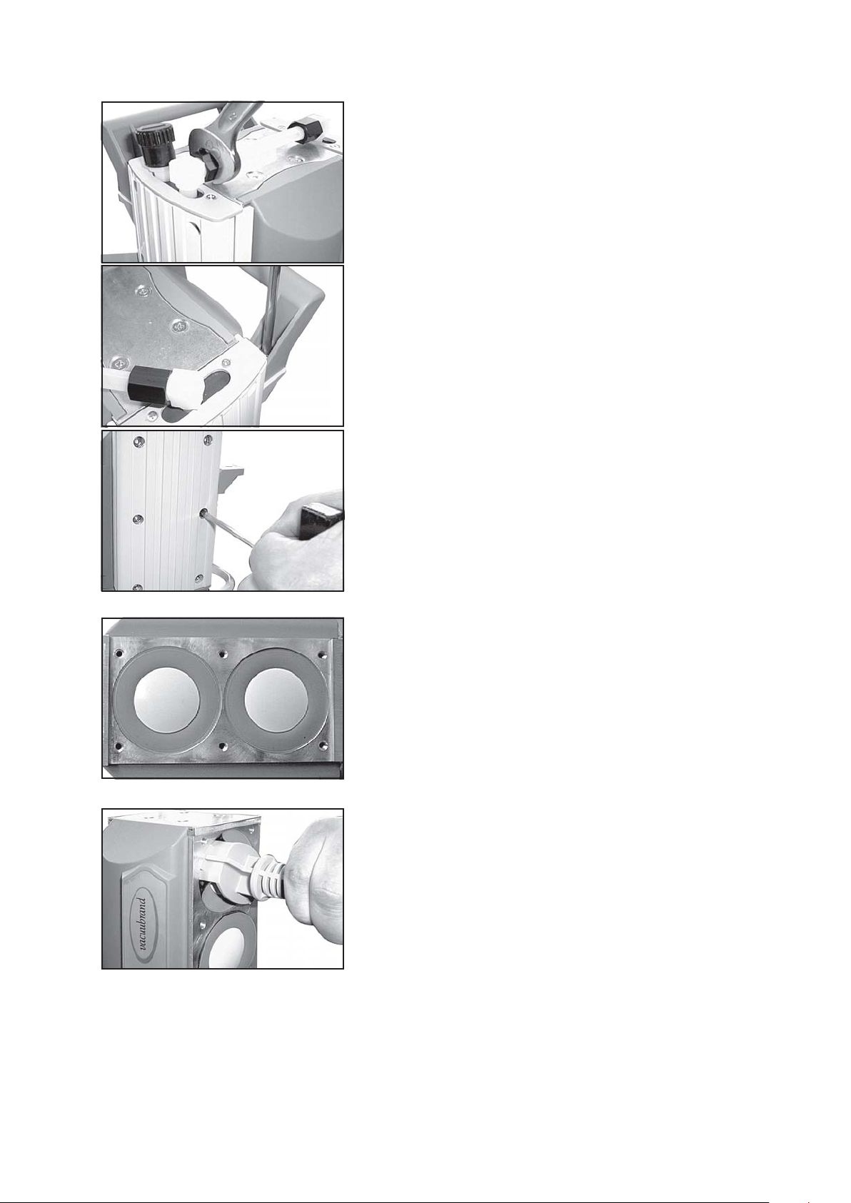
page 39 of 49
Use open-ended wrench to remove union nut at hose connection next to the gas ballast.
Use open ended wrench (w/f 15) to turn elbow fitting 1/4 of a
turn, reconnect hose. Do not remove the elbow fitting from the
pump head.
☞ Through reassembly a leak may result.
Use Phillips screw driver to unscrew the handle at one side of
the housing cover.
It is not necessary to disassemble the exhaust waste vapour
condenser.
Use hex key to remove six socket head screws from pump
head and remove upper housing (housing cover, housing cover
insert and head cover).
☞ Never remove parts by using a spiky or sharp-edged tool (e.
g. screw driver), we recommend to use a rubber mallet or
compressed air (to be blown carefully into port).
Remove head cover from housing cover and check valves. Note
position of valves and remove.
☞ Replace valves if necessary.
Use petroleum ether or industrial solvent to remove deposits.
Do not inhale.
Check diaphragm for damage and replace if necessary.
Replacing the diaphragm:
Lift diaphragm carefully.
☞ Apply pressure to the clamping disc beside the diaphragm
to bring connecting rod into upper turning point position if
necessary.
☞ Never use a spiky or sharp-edged tool to lift the diaphragm.
Use diaphragm key to grip under the diaphragm to the diaphragm
support disc.
Apply pressure to the diaphragm clamping disc to bring the diaphragm into lower turning point position. Press diaphragm key
against diaphragm clamping disc and remove diaphragm support disc with diaphragm.
☞ If the old diaphragm is difficult to separate from the support
disc, immerse assembly in naphtha or petroleum ether. Do
not inhale!
☞ Check for washers under clamping disc. Do not mix the wash-
ers from the different heads. Make sure that the original
number is reassembled at the individual pump head.
Documents are only to be used and distributed completely and unchanged. It is strictly the users´ responsibility to check
carefully the validity of this document with respect to his product. manual-no.: 999100 / 06/05/2008
Page 40
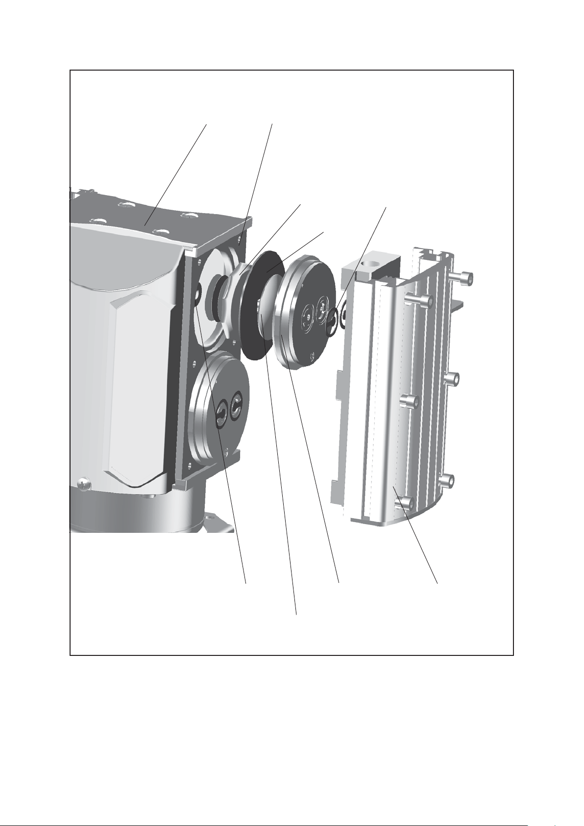
page 40 of 49
View of the disassembled pump head parts
bearing plate
housing
diaphragm
support disc
valve
diaphragm
rod
head cover
housing cover
diaphragm clamping disc
with connecting screw
Documents are only to be used and distributed completely and unchanged. It is strictly the users´ responsibility to check
carefully the validity of this document with respect to his product. manual-no.: 999100 / 06/05/2008
Page 41
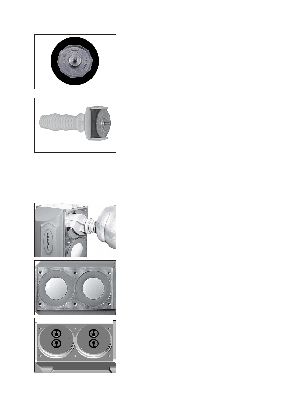
page 41 of 49
Position new diaphragm between diaphragm clamping disc with
square head screw and diaphragm support disc.
☞ Note: Position diaphragm with light-coloured PTFE side to
diaphragm clamping disc (to pump chamber).
Lift diaphragm at the side and position carefully together with
diaphragm clamping disc and diaphragm support disc in the
diaphragm key.
☞ Avoid damage of the diaphragm: Do not crack diaphragm in
a way that light lines occur on the upper side of the dia-
phragm.
Check for washers. Do not mix the washers from the different
heads. Make sure that the original number is reassembled at
the individual pump head.
☞ Smaller number of washers: The pump will not attain final
vacuum. More washers: Clamping disc will hit head cover;
noise or even blockage of the pump.
Assembling pump heads:
☞ Make sure that the square head screw of the diaphragm
clamping disc is correctly seated in the guide hole of the
diaphragm support disc.
Assemble diaphragm clamping disc, diaphragm and diaphragm
support disc to connecting rod.
☞ Position washers if available between diaphragm support disc
and rod.
Bring diaphragm into a position in which diaphragm is in contact
with housing and centred with respect to bore.
Position pumping unit on the side and support appropriately.
Assemble head covers and valves.
☞ Check for correct position (see fig. below).
Documents are only to be used and distributed completely and unchanged. It is strictly the users´ responsibility to check
carefully the validity of this document with respect to his product. manual-no.: 999100 / 06/05/2008
Page 42
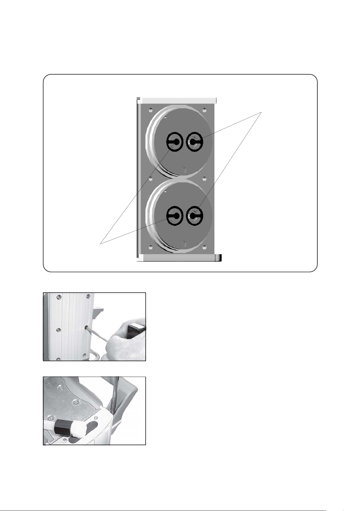
page 42 of 49
Comply with position and orientation of the head covers and the
valves definitely.
scheme of pump head with head covers and valves
”side with hose connection”
valves at the inlet
(kidney-shaped
opening beside
valve)
valves at the outlet
(round centred
opening under
valve)
”motor side”
Position housing cover.
☞ Move housing cover slightly to make sure that the head co-
vers are correctly positioned.
Screw in six socket head screws fixing housing cover crosswise first slightly, then tighten.
☞ Do not tighten until head cover is in contact with housing,
max. torque 6 Nm.
☞ Inspect the other pump heads (side of the exhaust waste
vapour condenser) the same way.
Assemble the handle.
Documents are only to be used and distributed completely and unchanged. It is strictly the users´ responsibility to check
carefully the validity of this document with respect to his product. manual-no.: 999100 / 06/05/2008
Page 43
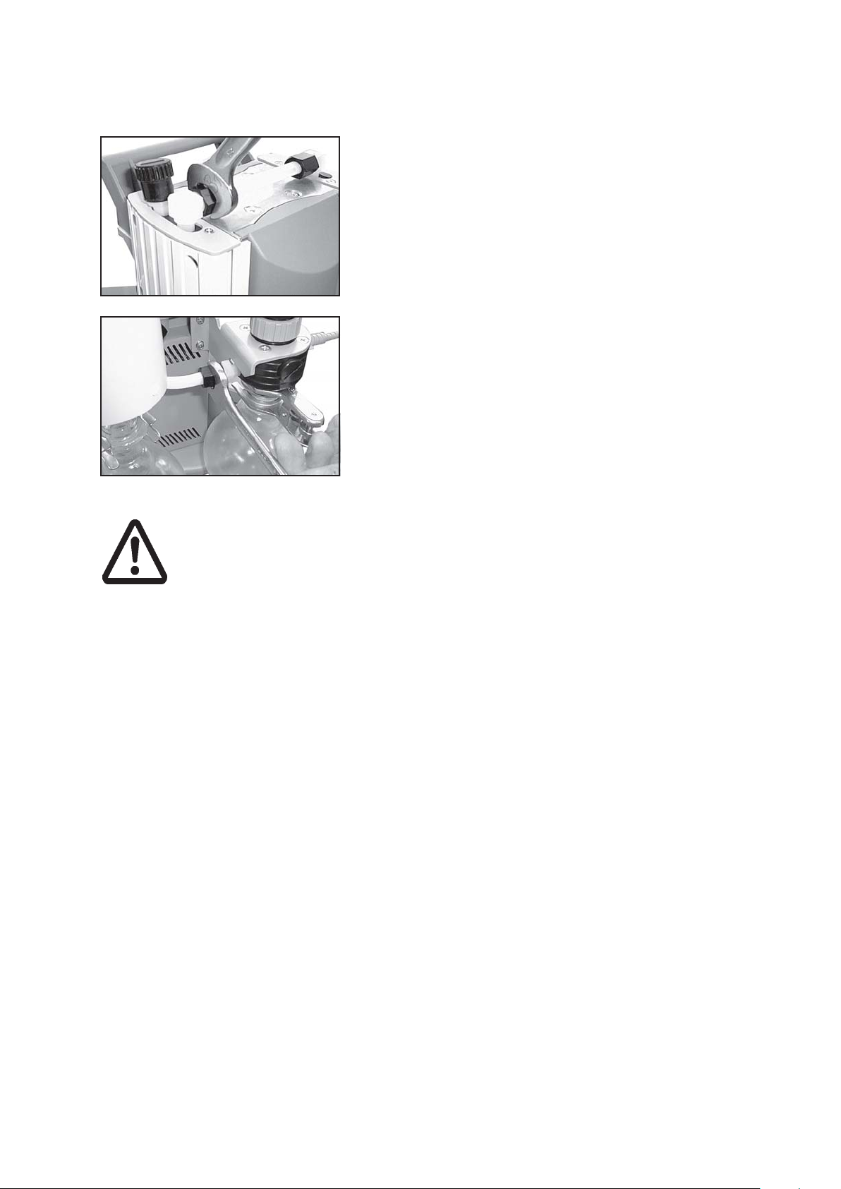
Assembling of fittings:
page 43 of 49
Use open ended wrench to reconnect hose to elbow fitting.
Tighten union nuts first by hand and then tighten one full turn
using open ended wrench.
Connect hose to fitting.
Tighten union nuts first by hand and then tighten one full turn
using open ended wrench.
If the pump does not achieve the ultimate pressure:
☞ In case the diaphragms and valves have been replaced, a run-in period of several
hours is required before the pump achieves its ultimate vacuum.
If all pump heads achieve a vacuum below 90 mbar but pump does not achieve the
ultimate total pressure:
Check hose connectors between pump heads and manifolds for leaks. If necessary
recheck pump chamber.
Documents are only to be used and distributed completely and unchanged. It is strictly the users´ responsibility to check
carefully the validity of this document with respect to his product. manual-no.: 999100 / 06/05/2008
Page 44
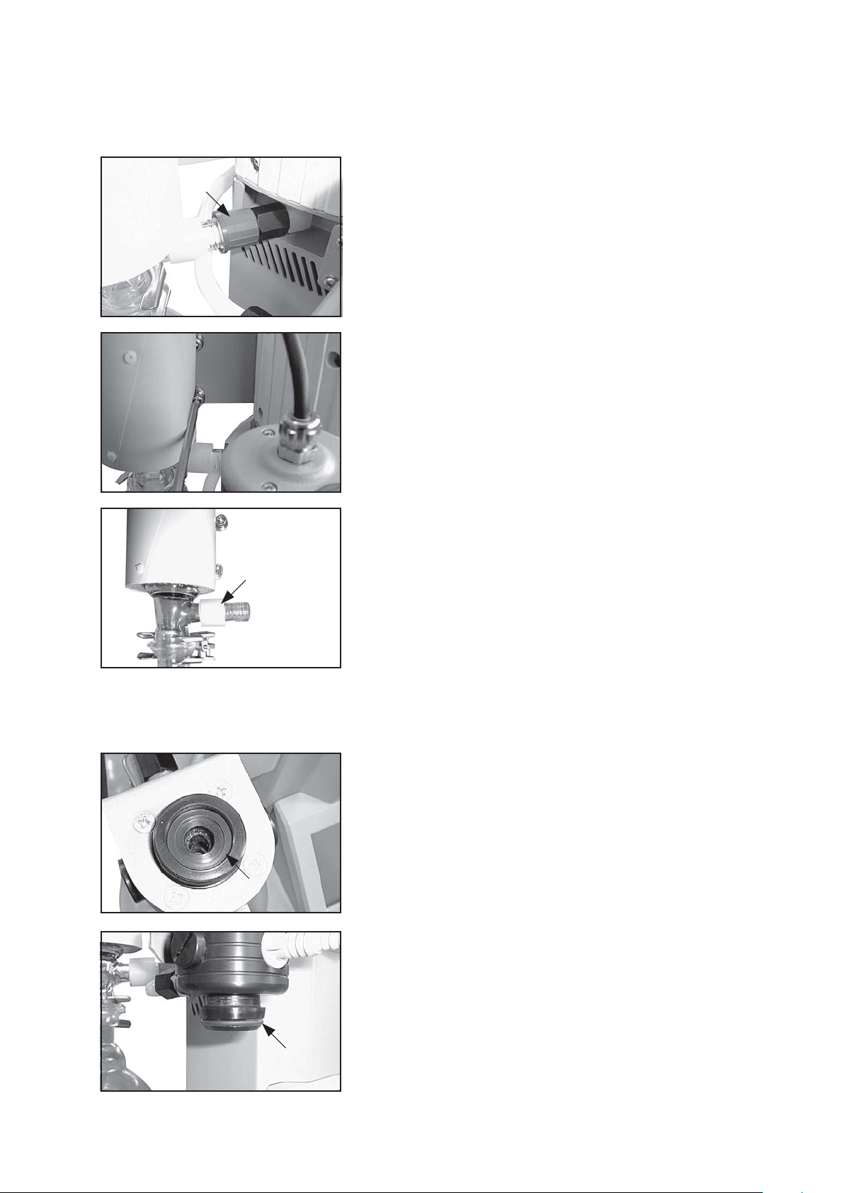
page 44 of 49
Cleaning and assembling components
Overpressure safety relief device ............................. 638821
(at the exhaust waste vapour condenser)
☞ Remove union nut at the condenser and remove hose from
the inlet of the condenser.
☞ Unscrew the exhaust waste vapour condenser from the
pumping unit.
☞ Pull off old overpressure safety relief device and install new
one. Check for correct position of the PTFE-foil under the
overpressure safety relief device.
☞ Assemble exhaust waste vapour condenser to the pumping
unit.
Seal ring 19 x 24.4 ..................................................... 637259
(FPM) at the pressure transducer
Round bottom flask 500 ml, coated .......................... 638497
O-ring 28 x 2,5 ......................................................... 3120553
(FPM) at the spherical ground joint of the round bottom flask at
the inlet
Documents are only to be used and distributed completely and unchanged. It is strictly the users´ responsibility to check
carefully the validity of this document with respect to his product. manual-no.: 999100 / 06/05/2008
Page 45

page 45 of 49
Cleaning the gauge head VSK 5
The gauge itself is maintenance-free.
If the vacuum system is contaminated (oil, particles, etc.), contamination of the pressure transducer will
influence the accuracy of measurement.
➨➨
➨ Fill the gauge head chamber with a solvent (e. g. benzene) and allow sufficient cleaning time. Observe
➨➨
all regulations concerning usage and disposal of solvents!
➨➨
➨ Drain the solvent and dispose of in accordance with regulations, repeat cleaning if necessary.
➨➨
➨➨
➨ Rinse the gauge head chamber several times with alcohol in order to remove all solvent residues.
➨➨
☞ Never use a spiky or sharp-edged tool to clean the pressure transducer.
➨➨
➨ Allow the pressure transducer to dry.
➨➨
➨➨
➨ Readjust the pressure transducer if necessary.
➨➨
Calibration in the factory
Control of measuring equipment
The VACUUBRAND DKD calibration laboratory is accredited by the Physikalisch-Technische Bundesanstalt
(PTB; German national institute for science and technology and the highest technical authority of the
Federal Republic of Germany for the field of meteorology and certain sectors of safety engineering) for the
measurable variable pressure in the pressure range from 10-3 mbar to 1000 mbar in accordance with
the general criteria for the operation of testing laboratories defined in the DIN EN ISO/IEC 17025:2000
series of standards.
Calibration in the VACUUBRAND calibration laboratory:
- To meet the requirements of the DIN ISO 9000ff and 10012 series of standards regarding the calibration
of inspection, measuring and test equipment at specified intervals.
- To document that the vacuum gauges calibrated are traceable to national standards of the PTB.
Documents are only to be used and distributed completely and unchanged. It is strictly the users´ responsibility to check
carefully the validity of this document with respect to his product. manual-no.: 999100 / 06/05/2008
Page 46
page 46 of 49
Notes on return to the factory
Repair - return - DKD calibration
Safety and health of our staff, laws and regulations regarding the handling of dangerous goods, occupational health and safety regulations and regulations regarding safe
disposal of waste require that for all pumps and other products the “Health and safety
clearance form“ must be send to our office duly completed and signed before any
equipment is dispatched to our premises.
Fax or post a completed copy of the health and safety clearance form to us in advance.
The declaration must arrive before the equipment. Enclose a second completed copy
with the product. If the equipment is contaminated you must notify the carrier.
No repair / DKD calibration is possible unless the correctly completed form is
returned. Inevitably, there will be a delay in processing the equipment if information is missing or if this procedure is not complied with.
If the product has come in contact with chemicals, radioactive substances or other
substances dangerous to health or environment, the product must be decontaminated
prior to sending it back to the factory.
☞ Return the product to us disassembled and cleaned and accompanied by a cer-
tificate verifying decontamination or
☞ Contact an industrial cleaning and decontamination service directly or
☞ Authorize us to send the product to an industrial cleaning facility at your expense.
To expedite repair and to reduce costs, please enclose a detailed description of the
problem and the product´s operating conditions with every product returned for repair.
We submit quotations only on request and always at the customer´s expense. If an
order is given, the costs incurred are offset from the costs for repair or from the purchase price, if the customer prefers to buy a new product instead of repairing the
defective one.
☞☞
☞ If you do not wish a repair on the basis of our quotation, the equipment might
☞☞
be returned to you disassembled and at your charge!
In many cases, the components must be cleaned in the factory prior to repair.
For cleaning we use an environmentally responsible water based process. Unfortunately the combined attack of elevated temperature, cleaning agent, ultrasonic treatment and mechanical stress (from pressurised water) may result in damage to the
paint. Please mark in the health and safety clearance form if you wish a repaint at
your expense just in case such a damage should occur.
We also replace parts due to optical aspects upon your request.
Before returning the equipment ensure that (if applicable):
☞ Oil has been drained and an adequate quantity of fresh oil has been filled in to
protect against corrosion.
☞ Equipment has been cleaned and/or decontaminated.
☞ All inlet and outlet ports have been sealed.
☞ Equipment has been properly packed, if necessary, please order an original pack-
aging (costs will be charged), marked as appropriate and the carrier has been notified.
☞ Ensure that the completed health and safety declaration is enclosed.
We hope for your understanding for these measures, which are beyond our control.
Scrapping and waste disposal:
Dispose of the equipment and any components removed from it safely in accordance
with all local and national safety and environmental requirements. Particular care must
be taken with components and waste oil which have been contaminated with dangerous substances from the process. Do not incinerate fluoroelastomer seals and “O“
rings.
☞ You may authorize us to dispose of the equipment at your expense.
Documents are only to be used and distributed completely and unchanged. It is strictly the users´ responsibility to check
carefully the validity of this document with respect to his product. manual-no.: 999100 / 06/05/2008
Page 47

page 47 of 49
Health and safety clearance form
Declaration concerning safety, potential hazards and safe disposal of waste, e. g. used oil.
Safety and health of our staff, laws and regulations regarding the handling of dangerous goods, occupational health and safety
regulations, safety at work laws and regulations regarding safe disposal of waste, e. g. waste oil, require that for all pumps and
other products this form must be send to our office duly completed and signed before any equipment is dispatched to our
premises. Products will not be accepted for any procedure and handling and repair / DKD calibration will not start
before we have received this declaration.
a) Fax or post a completed copy of this form to us in advance. The declaration must arrive before the equipment. Enclose
a second, completed copy with the product. If the product is contaminated you must notify the carrier (GGVE, GGVS,
RID, ADR).
b) Inevitably, the repair process will be delayed considerably, if this information is missing or this procedure is not complied with.
We hope for your understanding for these measures which are beyond our control and that you will assist us in expediting
the repair procedure.
c) Make sure that you know all about the substances which have been in contact with the equipment and that all
questions have been answered correctly and in detail.
1. Product (Model): ........................................
2. Serial No.: ..................................................
3. List of substances in contact with the
equipment or reaction products:
3.1 Chemical/substance name,
chemical symbol:
a) ...................................................................
b) ...................................................................
c) ...................................................................
d) ...................................................................
3.2 Important informations and precautions,
e. g. danger classification:
a) ...................................................................
b) ...................................................................
c) ...................................................................
d) ...................................................................
4. Declaration (please mark as applicable):
❑ 4.1 for non dangerous goods:
We assure for the returned product that
- neither toxic, corrosive, biologically active, explosive, radio-
active nor contamination dangerous in any way has
occurred.
- the product is free of dangerous substances.
- the oil or residues of pumped media have been drained.
❑ 4.2 for dangerous goods:
We assure for the returned product that
- all substances, toxic, corrosive, biologically active, explo-
sive, radioactive or dangerous in any way which have
pumped or been in contact with the product are listed in 3.1,
that the information is complete and that we have not
withheld any information.
- the product, in accordance with regulations, has been
❑ cleaned ❑ decontaminated ❑ sterilized.
5. Way of transport / carrier:
...........................................................................................
Day of dispatch to VACUUBRAND:
...........................................................................................
If the paint is damaged, we wish a repaint or
a replacement of parts due to optical
aspects at our expense (see ”Notes on return
to the factory”):
❑ yes ❑ no
We declare that the following measures where applicable - have been taken:
- The oil has been drained from the product.
Important: Dispose of according to national
regulations.
- The interior of the product has been cleaned.
- All inlet and outlet ports of the product have been
sealed.
- The product has been properly packed, if necessary,
please order an original packaging (costs will be
charged) and marked as appropriate.
- The carrier has been informed about the hazardous
nature of the goods (if applicable).
We assure VACUUBRAND that we accept liability for any
damage caused by providing incomplete or incorrect
information and that we shall indemnify VACUUBRAND from
any claims as regards damages from third parties.
We are aware that as expressed in § 823 BGB (Public
Law Code of Germany) we are directly liable for injuries or
damages suffered by third parties, particularly
VACUUBRAND employees occupied with handling/
repairing the product.
Signature: ...........................................................................
Name (print): ......................................................................
Job title (print): ...................................................................
Company´s seal: ...............................................................
Date: ...................................................................................
VACUUBRAND GMBH + CO KG
-Technology for Vacuum Systems-
© 2003 VACUUBRAND GMBH + CO KG Printed in Germany
Alfred-Zippe-Str. 4 - 97877 Wertheim
Tel.: +49 9342 808-0 - Fax: +49 9342 808-450
E-Mail: [email protected]
Web: www.vacuubrand.com
Documents are only to be used and distributed completely and unchanged. It is strictly the users´ responsibility to check
carefully the validity of this document with respect to his product. manual-no.: 999100 / 06/05/2008
Page 48
page 48 of 49
Konformitätserklärung
Declaration of conformity
Déclaration de conformité
Chemie-Pumpstand / Chemistry pumping unit / Groupe de pompage chimique
PC 2001VARIO (230V; 69 66 40, 69 66 41, 69 66 42)
Hiermit erklären wir, dass das oben bezeichnete Gerät in Konzeption und Bauart sowie in der von uns in
Verkehr gebrachten Ausführung den grundlegenden Anforderungen der zutreffenden, aufgeführten EURichtlinien entspricht. Bei einer mit uns nicht abgestimmten Änderung an dem Gerät verliert diese Erklärung ihre Gültigkeit.
We herewith declare that the product designated above is in compliance with the basic requirements of
the applicable EC-directives stated below with regard to design, type and model sold by us. This certificate
ceases to be valid if the product is modified without the agreement of the manufacturer.
Par la présente, nous déclarons que le dispositif désigné ci-dessus est conforme aux prescriptions de
base des directives EU applicables et indiqués en ci que concerne conception, dessin et modèle vendu par
nous-mêmes. Cette déclaration cesse d´être valable si des modifications sont apportées au dispositif
sans notre autorisation préalable.
Maschinenrichtlinie (mit Änderungen) / Machine directive (with supplements) / Directive Machines (avec
des suppléments)
2006/42/EG
Niederspannungsrichtlinie / Low-Voltage Directive / Directive Basse Tension
2006/95/EG
Richtlinie Elektromagnetische Verträglichkeit / Electromagnetic Compatibility Directive / Directive
Compatibilité Electromagnétique
2004/108/EG
Angewandte Harmonisierte Normen / Harmonized Standards applied / Normes Harmonisées utilisées
DIN EN 12100-2, DIN EN 61010-1, DIN EN 1012-2, DIN EN 61326-1
Managementsysteme / Management systems / Systèmes de Management
EN ISO 9001, EN ISO 14001 (1997-2006)
Wertheim, 05.05.2008
. . . . . . . . . . . . . . . . . . . . . . . . . . . .
Ort, Datum / place, date / lieu, date
. . . . . . . . . . . . . . . . . . . . . . . . . . . .
(Dr. F. Gitmans)
Geschäftsführer / Managing director / Gérant
ppa.
. . . . . . . . . . . . . . . . . . . . . . . . . . . . . . . . .
(Dr. J. Dirscherl)
Technischer Leiter / Technical Director / Directeur technique
VACUUBRAND GMBH + CO KG
-Vakuumtechnik im System-
-Technology for Vacuum Systems-
-Technologie pour système à vide-
Documents are only to be used and distributed completely and unchanged. It is strictly the users´ responsibility to check
carefully the validity of this document with respect to his product. manual-no.: 999100 / 06/05/2008
Alfred-Zippe-Str. 4 - 97877 Wertheim
Tel.: +49 9342 808-0 - Fax: +49 9342 808-450
E-Mail: [email protected]
Web: www.vacuubrand.com
Page 49

page 49 of 49
Disclaimer: Our technical literature is only intended to inform our customer. The validity of general empirical
values and results obtained under test conditions for specific applications depend on a number of factors
beyond our control. It is therefore strictly the users´ responsibility to very carefully check the validity of
application to their specific requirements. No claims arising from the information provided in this literature
will, consequently, be entertained.
VACUUBRAND GMBH + CO KG
-Technology for Vacuum Systems-
© 2008 VACUUBRAND GMBH + CO KG Printed in Germany
Documents are only to be used and distributed completely and unchanged. It is strictly the users´ responsibility to check
carefully the validity of this document with respect to his product. manual-no.: 999100 / 06/05/2008
Alfred-Zippe-Str. 4 - 97877 Wertheim
Tel.: +49 9342 808-0 - Fax: +49 9342 808-450
E-Mail: [email protected]
Web: www.vacuubrand.de
 Loading...