

Page 1
8CH DVR
Vehicle DVR System
Wi Fi / GPS / 3G (optional)
Wi Fi / GPS / 3 G (opt io nal)
This product contains accessories as below:
Storage devices such as hard drives, memory cards are not supplied,
please contact Transport Support - www.transportsupport.co.uk
Accessories
Product Appearance
Take and review some test video footage initially to make sure the images have been recorded
correctly. Please note that the manufacturer, its subsidiaries and aliates, and its
distributors are not liable for consequential damages arising from any malfunction
of this device or accessories, including memory devices that results in the failure of an image
to be recorded or to be recorded in a way that is unreadable.
Before using the product, please ensure that you read the safety precautions described
below. Always ensure that the product is used correctly.
Before using 3G products, please ensure that you read the safety notications
described below.
• Please keep device away from children.
• Use only recommended power sources.
• Do not attempt to disassemble, alter or apply heat to the product.
• Avoid dropping or subjecting the product to severe impacts.
• To avoid the risk of injury, do not touch the interior of the product if it has been dropped
or otherwise damaged.
• Stop using the product immediately if it emits smoke, a strange smell, or otherwise
behaves abnormally.
• Do not use organic solvents such as alcohol, benzene, or thinner to clean the product.
• Do not let the product come into contact with water (e.g. sea water) or other liquids.
• Do not allow liquids or foreign objects to enter the DVR.
• Do not place the DVR near or in direct ame.
• Do not handle the power cord with wet hands.
• Do not use the equipment in a manner that exceeds the rated capacity of the electrical
outlet or wiring accessories. Do not use if the power cord or plug are damaged, or not
fully plugged into the outlet.
• Do not allow direct or metal objects (such as pins or keys) to contact the terminals or
plug.
• Avoid using, placing or storing the product in the humid or dusty areas.
• Company and user shall not modify certied low power radio frequency device the
frequency, increase the power and change the characteristics and functions.
• Use low power radio frequency device shall not aect ight safety and interfere with
legal communications; if radio interference happenes the use of the device should be immediately
suspended.
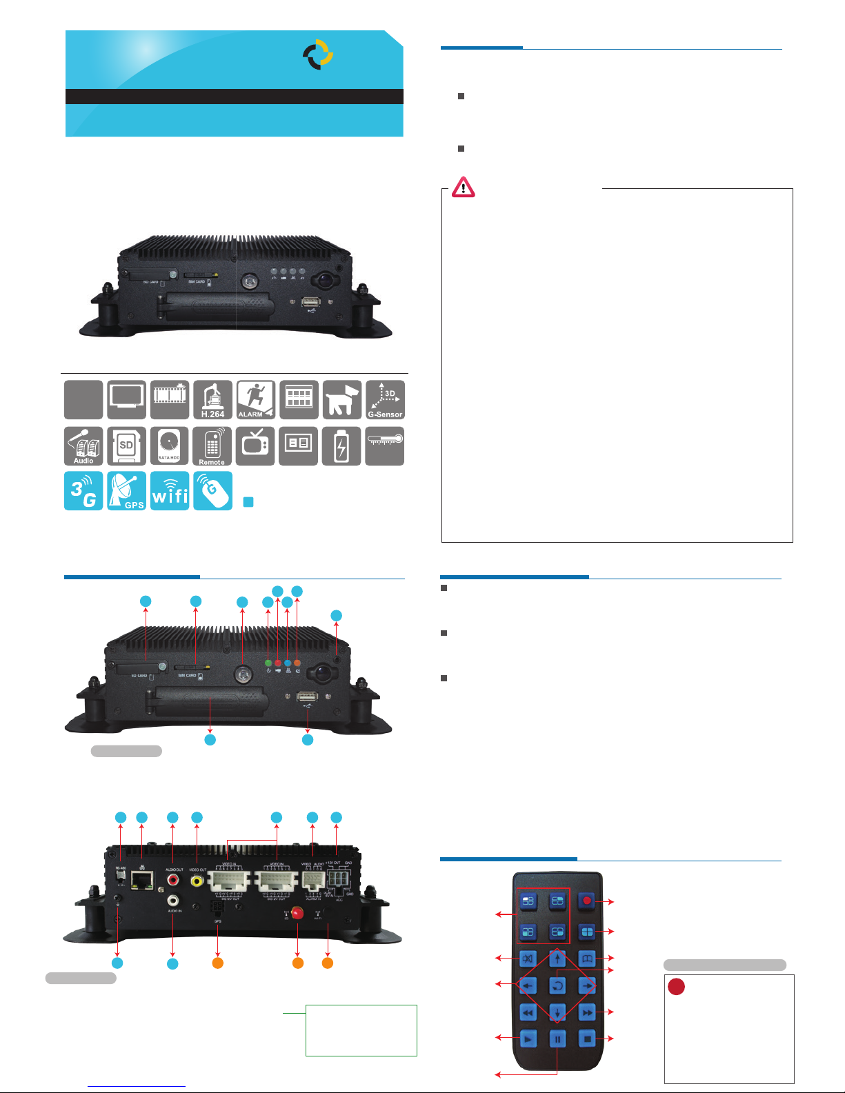
Light Indicators - Front Panel of the DVR
Power On / Power O
IR Remote controller
Standard
Optional
Safety Precautions
● Power Light (Green LED)
Light O: means no power/power o. Light On: means power supply normal and DVR is on.
● Recording Light (Red LED)
Light O:means not-recording. Light Flashing:means DVR is recording.
● Network Light (Blue LED)
Light O:means network disconnected. Light On:means network connected.
● GPS Light(Orange Light)
Light O: means GPS is not ready. Light On: means GPS is locked on position.
Power On
Put 2.5” HDD (upto 1TB) into HDD slot and close the HDD slot door and lock.
then turn on the power to the DVR, it will take approximately 30 seconds to start.
When the LED’s on the front panel start ashing, recording is in progress.
Power O
Turn o the power; please wait for 10 seconds until the super capacitor has
discharged and fully powered down. Then take the HDD out and playback the
recorded les in the PC Software.
optional
GUI
30 FPS
960H
960x480
-20~65°C
(vehicle inside)
DC 8~36V
TV OUT
8CH
Main Device / Power Cable 6P+5A / ALARM Cable / IR Extension
Cord /16P Female-MINI x2 / IR Remote Control/Network Cable /
Software Disc / RS-485 Cable(2 pin)
3G Module / WiFi Antenna / G-Mouse
1 2
3 456
7
8
9 10
11 12 13 14 15 16 17
19
20 21 2218
GPS / 3G / WiFi optonal
IMPORTANT! When the RED light is ashing quickly,itmeans a Forced recording is being
causedbymanualactivationorbyashockdetectedbytheG-Sensor.
Remark: While using playback function on the DVR, it cannot recordliveimages.
Remote control inspection
?
ˇ Check the batteries positive and
negative polarity.
ˇ Check the battery has charge.
ˇ Check the sensor of remote control
if be obscured.
ˇ Check if there are fluorescent
lamps are used nearby.
Remote Control Precautions
1CH Screen
Display
Force Recording Button
4CH Screen Display
Mute
Menu
Arrow
Conrm
Backward
Playback/
Play
Pause
Stop/Left
FRONT PANEL
1. SD Card Slot
2. Sim card slot
3. HD slot lock
4. Power light
8. Infrared Receiver
9. HD slot
10. USB Slot
5. Record light
6. Network light
7. GPS light
REAR PANEL
11. RS-485 Connection
12. Network Connection
13. Audio output
14. Video output
15. Hollow connection Video
recorder connection 1-4 CH
16. Hollow connection
1 set of video/ audio output
4 set of alarm input
17. Power Connection
18. GND
19. Audio input
20. G-Mouse connection
21. 3G antenna connection
22. WiFi antenna connection
1. DC12V Out
2/3. Signal & DC grounding
4. DC8~36V vehicle power (+)
5. ACC control
6. GNDP vehicle power (-)
TS
TRANSPORT SUPPORT
Page 2
System Interface and Operation
3G Setting *Optional
Playback on PC site
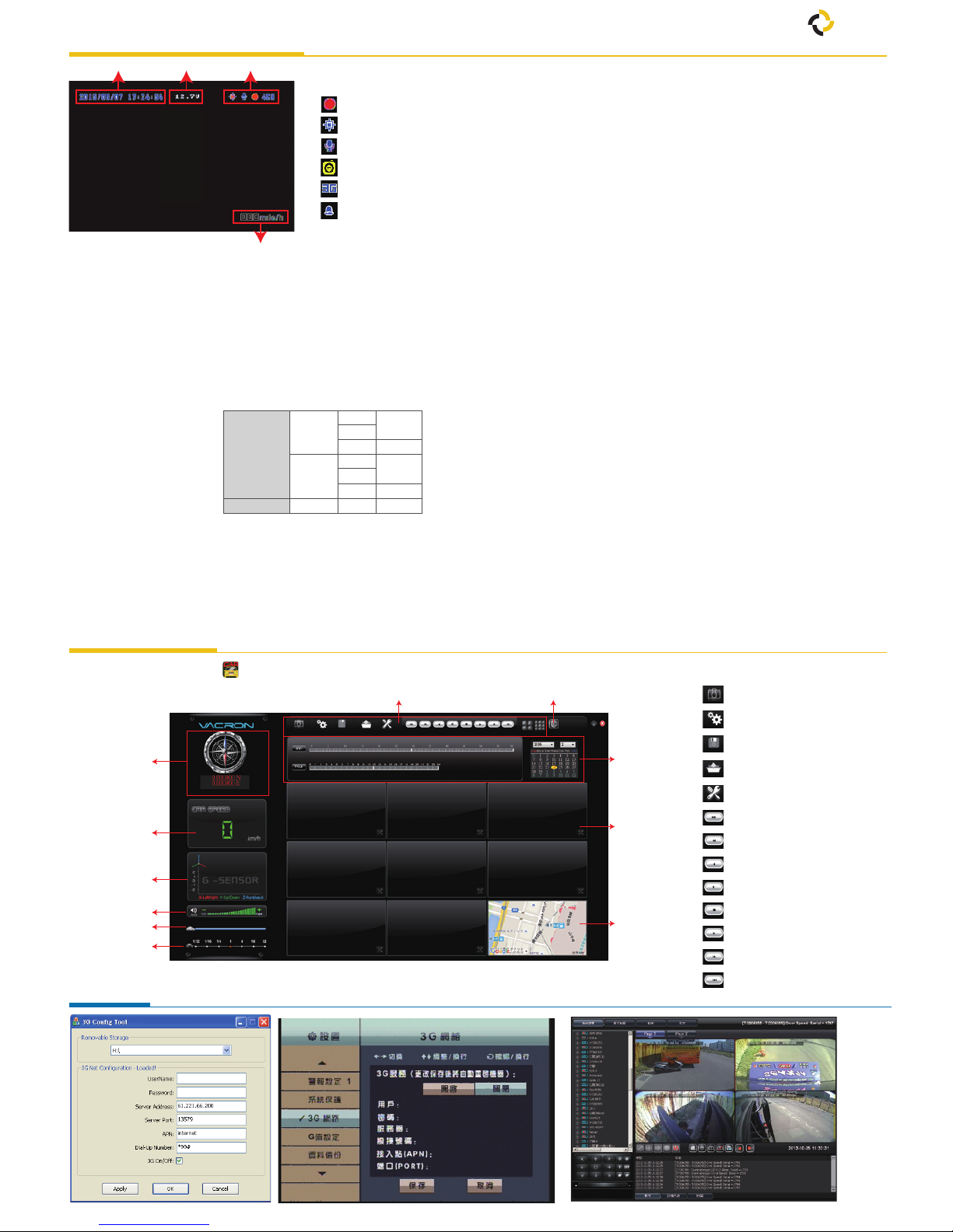
B. Display Description
C. OSD Menu Operation and Parameters Setup Description
• Recording Setting
5-20fps
30fps
5-20fps
25fps
High
960H
D1
CIF
960H
D1
CIF
Better
NTSC
PAL
Normal
Recording
Frame
Resolution
8ch Split Display (1~8ch)
• Press Ch1~Ch8 button or select on menu for single display.
• Press quad split screen button for 4Ch display
• Press quad split screen button repeatedly to show CH1~4 display
or CH5~8 display
• Press menu button to enter menu option.
• Press play button to enter playback mode.
: Snapshot
: Conguration
: Disk Backup
: Playback
: HDD format, language setting
: Previous File
: Previous Frame
: Video backwind play
: Pause
: Stop
: Play
: Next Frame
: Next le
Control Interface Description
3G Client Remote Monitoring3G Setting on DVR OSD G-Network Setting on pc
Function Icon
Speed
VersionDate/Time
A. Icon Description
• : Recording
• : GPS Connecting
• : Voice Recording On
• : Event Recording On
• : 3G Connection On
• : Alarm Trigged
• Video Setting
Select 1~4CH to adjust Bright, Contrast and Color.
• Time Setting
The time setting will be automatically calibrated by GPS signal.
If no GPS signal, time and date can be set manually.
Select to show speed and speed unit setting on live view display or Not.
• GPS Setting
• Plate Number Setting
Input range:A~Z and 0~9.
• Working Mode
1. Setup channel mode when system starts.
2. Select DVR run time after ACC O.
3. Sound recording ON/OFF.
• Alarm Setting
Setup the mode of operation when an after alarm is trigged.
• System Protection
1. Low voltage protection (trigged at ACC mode) .
2. HDD error warning.
• 3G Network (Optional)
3G function ON/OFF,show setting information at present (optional).
• G-Sensor Setting
Once the function is activated, if a collision happenes,
[Force Recording]mode will be automatically triggered, to prevent
overwriting of the recorded event.
• Data Backup
Allows selection of video les to backup/export.
• Restore Default
• Format HDD
• Firmware Update
Restore default settings - the DVR will be restarted and
restored to factory settings.
Full format of the HDD - All data on HDD will be deleted.
Save the rmware update program onto a USB device and use the USB
device to update rmware. When rmware update is in progress
DO NOT SWITCH OFF THE POWER TO THE DVR.
DVR will restart automatically after nishing update.
1. Execute the CarBox2.exe from CD-ROM, the display will be as shown below.
GPS
Coordinate
G-Sensor
Volume
Play BAR
Play speed
Speed
Google MapControl Interface
Google Map
Playback
date selection
1~8 CH
ìGPS Coordinate, Speed and Google Map (select models with 3G modules)
TS
TRANSPORT SUPPORT
 Loading...