

Page 1
Specification
Features
H11ANK7001
16ch H.264
Network Video Recorder
Quick User Guide
1
2
3
4
5
6
7
8
9
10
11
12
Motion
Alarm
VGA OUT HD OUT
1920x10801920x1080
Full HD
1080P
16 Channel
System
Storage Device/
Interface
User Interface
Video And Other
I/O Interface
CPU: TI SoC
Operating system:Linux
Build in SATA interface x 4, compatible SATA/SATAII HDD( Max. 3TB)
Support E-SATA interface and External E-SATA RAID function
HDD Caddy x1
DVD burner x1(Optional)
(DVG RW / DVD ±R;DVD burner occupied one interface of SAT A)
35 operating buttons on Front panel / shuttle play controller
NVR IR remote control x1
RS-232 x1 –support SMS sending device, SMS generate automatically when Alarm activated
3 Video outputs: HD output x2 and VGA x1 ;
The alternatives are HD1 and VGA;HD2 is reserved.
USB 2.0 x2 – connect to an external USB devices (mouse or USB flash)
Alarm OUT x4 / Alarm IN x16
Headphones (speakers) sound output x1 (left and right)
Microphone audio input jack x1 (left and right)
Ethernet x2 – 10/100/1000 (IEEE 802.3 Type 10Base-T /
IEEE 802.3u Type 100Base-TX / IEEE 802.3ab Type 1000Base-T);Auto-MDIX.
IPv4、ARP、TCP、UDP、ICMP、DHCP、NTP、DDNS、SMTP、FTP、
HTTP、RTP、RTSP、RTCP
H.264 compression format
E-Map
Real-time Live View capable 16CH VGA @30fps or 4CH 1080P @23fps
4-CH 1080P @23fps Synchronous Playback
Recording Query: Time search, Event search (IP CAM displacement,
Alarm I / O triggered alarm notification)
Playback speed/ slow forward / fast forward in 5 different
speed, Play Frame by Frame mode (forward or backward)
Pentaplex operation: Live/ Record/ Playback
Support e-mail / SMS / Mobile App message notifications
Event Notification : Alarm I / O trigger, Motion detection, Video loss, HDD error
Constant recording
Schedule recording
Alarm triggered recording (include motion detection recording): Complete event
video reserved 10 seconds before and 60 minutes after event taken place.
Schedule alarm triggered recording
(include motion detection recording):
Complete
event video reserved 10 seconds before and 60 minutes after event taken place.
Manual recording
Only recording without live (depending on user authority)
Video output format: AVI
The dump media directly burn to CD / DVD (optional) USB mobile storage device or remote NAS
Remote Client software; live, playback set up by PC (remote side)
Authorization: Maximum 10 group accounts, Hierarchical authority
Support 3 users log on by Client-side software or browser.
Systems operation records, record login time, IP and selected video.
Browser: MS IE7-IE9 / Fire Fox / Safari / Chrome
Support megapixel IP Camera video
Support CCTV camera video via Video Server.
DC12V / 8.33A ( accessory 110V-240V 2.5A / DC12V 8.33A ADAPTER x 1)
0-45
℃
Network Protocol
Video Format
Live / Playback
Event Notification
Recording Mode
Backup Management
System Management
Support Equipment
Power
Operating Temperature
Record
LOG
PLAY BACK
AUDIO: Record Audio
PREV: Prev. Page
LIVE: Live View
ID:NVR ID
NEXT: Next Page
SEQ: Sequential Mode
PTZ Controller
Enter / Arrows Keys
Display Mode
Single Channel Mode
★Product specifications are subject to change without notice; please contact us for the latest information.
CAUTION
For your safety, please read the manual
and follow the instructions carefully
before you install the DVR.
Do not expose the DVR under the sunlight, heat or wet
environment while installation. As it could decrease the
performance of DVR and damage the machine.
Do not touch the power plug or case with wet hands
as this could result electric shock.
Do not forcedly bend or put heavy object
on power cable as this could result in injury to
personal or equipment.
Do not operate with damaged power cord or loose
electrical outlet as this could result in electric shock or accident.
Please use individual power instead of share electrical
outlets with other electrical equipment as this could
result in damage or accident.
Do not attempt to service this DVR by yourself as it may
expose you to dangerous voltage or other hazards.
Please refer all service to the qualified servicing distributor.
Please do not remove the machine housing during operation.
It may cause electric shock or accidental injury.
Do not place the machine on an uneven surface
or it would decrease the DVR efficiency or malfunction.
Avoid any shock or bumping of the DVR while recording.
Improper handling could damage the system.
CAUTION
‧Please install the SATA HDD and connect all of SATA
power lead & data cable before switch on the machine.
‧Please check the voltage is fit for the NVR.
‧Please check the connection with other device is right or not.
‧Please insert the power line.
‧The power light is red after the NVR is power on.
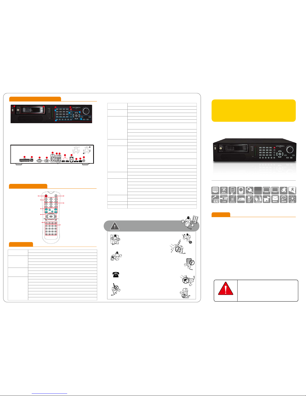
A) USB slot B) Lockable removable hard drive tray. C) Power switch
D) Operating on front panel is identical to operating on remote controller.
Please refer to section of remote controller for instructions.
1) Single channel buttons 2) Display mode: 4, 9, 16 channel viewing
3) Arrow keys / Enter
4) Playback keys: fast forward/rewind/play/pause/stop keys, and jog shuttle
5) Quick buttons: Record/Live/Play/Sequence/Next/Screen.
1) Alarm Input
2) Alarm Output
3) RS-232
4) XGA Output
5) Video Output
6) Audio Input
7) Audio Output
8) HD Output x 2 (For single display, please use HD OUT 1)
9) LAN x2 port
10) E-SATA Output
11) USB 2.0
12) DC12V
Front Panel & Installation
Remote Controller
B
C
D
1
2
3
4
5
A
2013 AUG V1.0
Network video recording system
•TI SoC CPU special design for NVR with the best image process efficiency.
•Support 4 units of SATA/SATA II device up to 12TB HDD recording capacity.
•Advanced H.264 compress technology provides the best HDD space usage.
•Embedded Linux system, to eliminate the threat from virus and hacking.
•Support 16CHs of IP camera (1080P) video and also support analogue
camera video with optional Video server.
•HD output and E-SATA.
•Support IP CAM position layout and editable user definition.
•Variety of backup management can directly burn to CD / DVDR-RW (optional),
USB storage device or NAS.
•Support 3 users log on by Client-side software or browser.
Page 2
DISPLAY CAMERA RECORD EVENT
AUDIO STORAGE BACKUP SYSTEM
SETUP
Operation Setup
Advanced Features
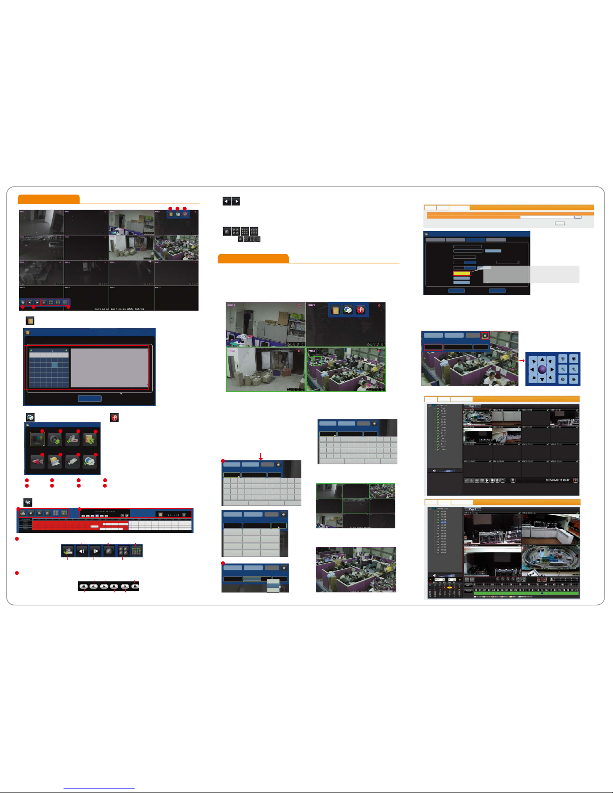
A) Log
A B C
D
B) Setup
C) Manual Record
(One Step Quick Recording)
1. Right click then click on [Emergency] at
quick launch bar to record video streaming
sent from all IP cameras.
2. Click it again to stop recording.
3. After emergency recording, all manual
recording channels will be blocked with blue
squares.
4.The data is indicated in black color on time
bar in playback.
E F
D) Playback
E) Previous and Next and Previous Page
1. Click to go to previous / next four channel viewing.
2. Click the yellow arrows on center point of left and right side of screen to go to previous/next four
channel viewing.
F) Display Mode
1. Click for 1, 4, 9, or 16 channel viewing
21
3
4
5
6
7 8
Operations of Playback
1
1
2
1. Quick Adjustment Viewing Channel Layout.
1) The viewing channels are displayed in the order of IP address (e.g. xxx.xxx.xxx.001 is displayed
before xxx.xxx.xxx.002).
2) Two viewing channels may be swapped viewing squares.
3) Click, hold, (the edge of the viewing channel turns green), drag and drop the channel to the
desired position.
2. Quick Camera Info Display and
Modification
3. Quick Search for IP Address and
Name Change
4. Quick Selection of Viewing Channels
5. Zoom-In on Single Channel Display
6. Firmware Upgrade
8. Remote Monitoring and Playback
7. PTZ
live viewing
Pre page
Next page 4 CH
Arbitrary choice 4 CH
Single CH
2
Search
Play Forward (max. 32X)Reverse Playback by Frame
Forward Playback by FrameStopRevere (max. 32X)
1) Click the viewing channel for on-screen
keyboard.
2) Right click on the cell to change parameter
of the camera including camera name, IP
address, and port. It also allows you to copy,
paste, and delete.
1) Click top-left corner of a camera to bring up parameter ofcamera info.
2) Click PTZ icon on top-right corner for on-screen directional control panel.
3) On-screen PTZ directional control panel stays on screen during live viewing.
2
1
5
6
3
4
7 8
LOG
September 2013
S M T W T F S
25 26 27 28 29 30 31
1 2 3 4 5 6 7
8 9 10 11 12 13 14
15 16 17 18 19 20 21
22 23 24 25 26 27 28
29 30 1 2 3 4 5
EXIT
18:47:47-Motion Recording Stop for IPNC7
18:47:55-Motion Recording Stop for IPNC11
18:48:17-Motion Recording Stop for IPNC5
18:48:32-Motion Recording Stop for IPNC3
18:48:53-Motion Recording Stop for IPNC7
18:49:23-Motion Recording Stop for IPNC5
18:49:59-Motion Recording Stop for IPNC7
18:50:03-Motion Recording Stop for IPNC8
18:50:08-Motion Recording Stop for IPNC3
18:50:48-Motion Recording Stop for IPNC5
18:51:06-Motion Recording Stop for IPNC7
18:51:21-Motion Recording Stop for IPNC8
18:51:39-System reboot
DISPLAY CAMERA RECORD EVENT
AUDIO STORAGE BACKUP SYSTEM
LiveView
PlayBack Firmware Upgrade
LiveView
PlayBack Firmware Upgrade
CONNECT DISPLAY APPLY
NAME IP PORT
IPNC8 192.168.1.29 80
Shift Caps Backspace
IPNC3 192.168.1.23 80
12 345 67 89 0qwe r t yu i o p
=
as df gh j kl ;
‘
zx cvb nm, . [ ]
CONNECT DISPLAY APPLY
NAME IP PORT
Shift Caps Backspace
IPNC3 192.168.1.23 80
12 345 67 89 0qwe r t yu i o p
=
as df gh j kl ;
‘
zx cvb nm, . [ ]
CONNECT DISPLAY APPLY
NAME IP PORT
CONNECT DISPLAY APPLY
NAME IP PORT
IPNC3 192.168.1.23 80
123
456
7.89
0
Backspace
IPNC3 192.168.1.23 8C
COPY
PASTE
DELETE
192.168.1.23
CONNECT DISPLAY APPLY
NAME IP PORT
1
2
LiveView PlayBack
Firmware Upgrade
Please select upgrade file
Upgrade Server
upgrade
瀏覽
INFORMATION NETWORK SETUP PASSWORD
SYSTEM
CURRENT DATE / TIME:
CONFIG DATE / TIME:
LANGUAGE:
SYNC IPCAM PARA:
IPCAM FLOOR PLAN:
FIRMWARE UPDATE:
CONFIG INITIALIZE:
SYSTEM REBOOT:
APPLY TIME
LOAD IMAGE
SYNC PARA TIME:
SAVE EXIT
ENGLISH
2013.09.05. PM 06:47:51
2013.09.05. PM 06:47:52
ENABLE DISABLE
ENABLE DISABLE
05 MIN
USB UPDATE
CONFIG INIT
REBOOT
MAGE
If new firmware is saved on a USB flash memory,
click [USB UPDATE] to begin firmware upgrade.
 Loading...