

VAC V200 Series, V200FF, V200EX, V200 Installation, Operation And Maintenance Manual
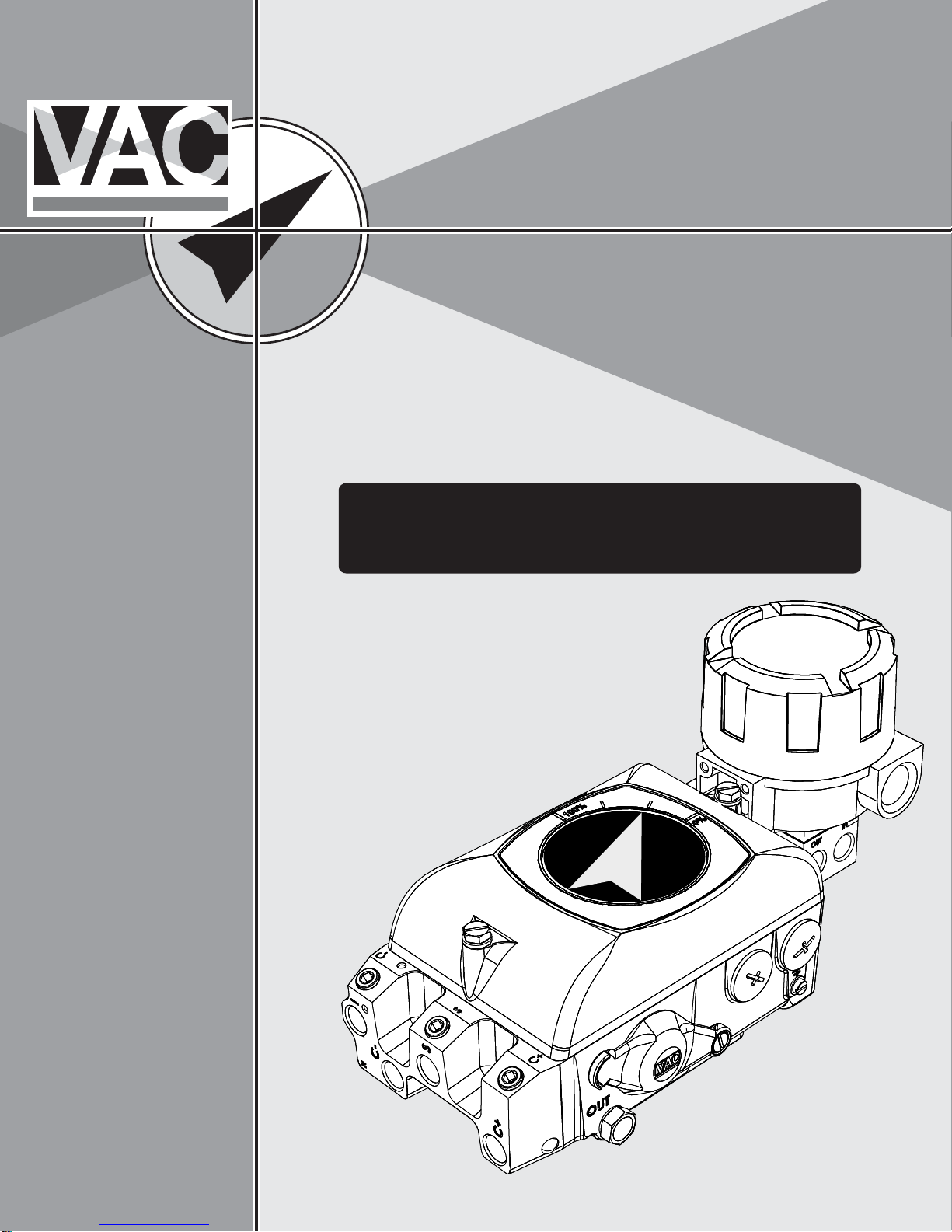
V200 POSITIONER
www.vacaccessories.com/v200
Valve Accessories & Controls
V200 EXTERNAL OPTION
Installation,
Operation and
Maintenance
Instruction
1 V200 External options IOM r2


V200 POSITIONER
www.vacaccessories.com/v200
CONTENTS
1 INTRODUCTION ................................................................................. 4
1.1 Air quality recommendations.................................................. 4
1.2 Safety Instructions ................................................................ 4
2 INST ALLA TION .................................................................................. 5
2.1 Installing external IP converter on V200P .............................. 5
2.2 Installing external IP converter on V200E .............................. 6
2.3 Main supply filter for IP con verter .......................................... 7
3 SP ARE PARTS.................................................................................. 8
3.1 Exploded drawing external options ......................................... 8
3.2 Spare parts list external options ............................................ 9
4 SPECIFICATIONS ............................................................................. 10
4.1 Specifications external options .............................................. 10
5 DIMENSIONS .................................................................................... 11
7.1 V200 E 0-10V ........................................................................ 11
7.2 V200 EX and V200 EX-GA .................................................... 12
7.3 V200 FF................................................................................. 13
3 V200 External options IOM r2
V200 POSITIONER
www.vacaccessories.com/v200
1 INTRODUCTION
1.1 Air quality recommendations
Poor air quality is one of the main causes of
premature functional problems with pneumatic
and electropneumatic equipment. The pilot
valve and IP converter are precision instruments, and are therefore the most sensitive
parts of the positioner.
a) W ater in the supply air is a natural occurrence. This happens when air is compressed.
The compression heats the air and the natural
degree of water in the air can remain as moisture. When the air cools in pipes etc.
the moisture condenses and becomes liquid
water . Large quantities can build and sometimes flood small water separators. This excess water will eventually reach the control
valve and positioner. This can cause corrosion
damage to the IP conv erter, causing the
unit to malfunction.
We strongly recommend the use of water
separators with adequate capacity. Coalesing
filters from a reputable manufacturer is an
inexpensive way to help prevent unit malfunctions or failures, and add life to the product.
These filters remove particles and moisture
from air lines.
b) Oil in the supply air usually is from the main
compressor. Oil can clog the small nozzles and
disturb the flapper in the IP converter. It can
also cause the spool to “drag” within the pilot
valv e . The result is poor control or in the worst
case, failure.
To ensure normal operational safety with VAC
positioner products, we recommend that a
water separator and a <80 micrometer filter are
mounted as close to the product as possible.
If large amounts of oil are present an oil separator should be installed as well.
To further increase operational safety, w e
recommend that the working air is clean, dry
and free of moisture, water , oil, particles and
other contaminants, in accordance with the ISA
Standard ISA S7.3-81.
1.2 Safety Instructions
CA UTION: Beware of moving parts
when positioner is operated!
CA UTION: Be ware of parts with
live voltage!
A voltage, which is normally not
dangerous, is supplied to the
positioner.
Avoid touching live parts and bare
wires as well as short circuiting live
parts and the housing.
CA UTION: Do not dismantle a
pressurized positioner!
Dismantling a pressurized positioner
will result in uncontrolled pressure
release. Always isolate the relevant
part of the pipeline. Release the pressure from the positioner and the piping. Failure to do this may result in
damage or personal injury.
c) Particles in the air usually occur because of
corrosion. Dirt and particles can block the
small nozzles of the IP converter.
They can also cause the pilot valve to malfunction. The unit may completely fail.
V200 External options IOM r24
CAUTION: Do not exceed the
positioner performance limitations!
Exceeding the limitations marked on
the positioner may cause damage to
the positioner , actuator and v alv e.
Damage or personal injury may result.
V200 POSITIONER
www.vacaccessories.com/v200
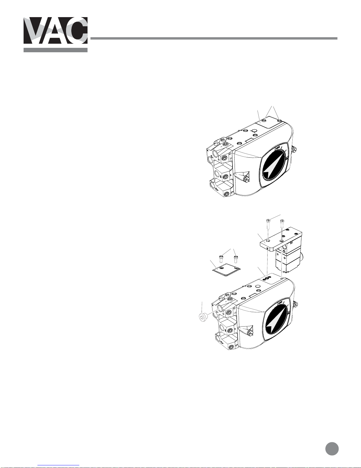
2 INSTALLATION
2.1 Installing external IP converter on V200P
NOTE! This instruction is for use when
converting from V200P to V200EX, V200FF or
other external IP converter .
When converting from V200E please follow the
instruction in section 2.2.
1. Loosen the two screws(1) and remove the
plate(2).
2. Make sure there are three O-rings(3) in the
positioner housing.
1
2
3. Install the IP converter(4) and tighten the
screws(5).
4. Install the 1/4” plug(6) in the port marked I.
5
4
1
2
3
6
5 V200 External options IOM r2
 Loading...