

VAC V100 Troubleshooting Manual
Trouble Shooting Guide for V100 Positioner
1) 1.V100 not responding to input signal
a) The tubing to the actuator may be
incorrect
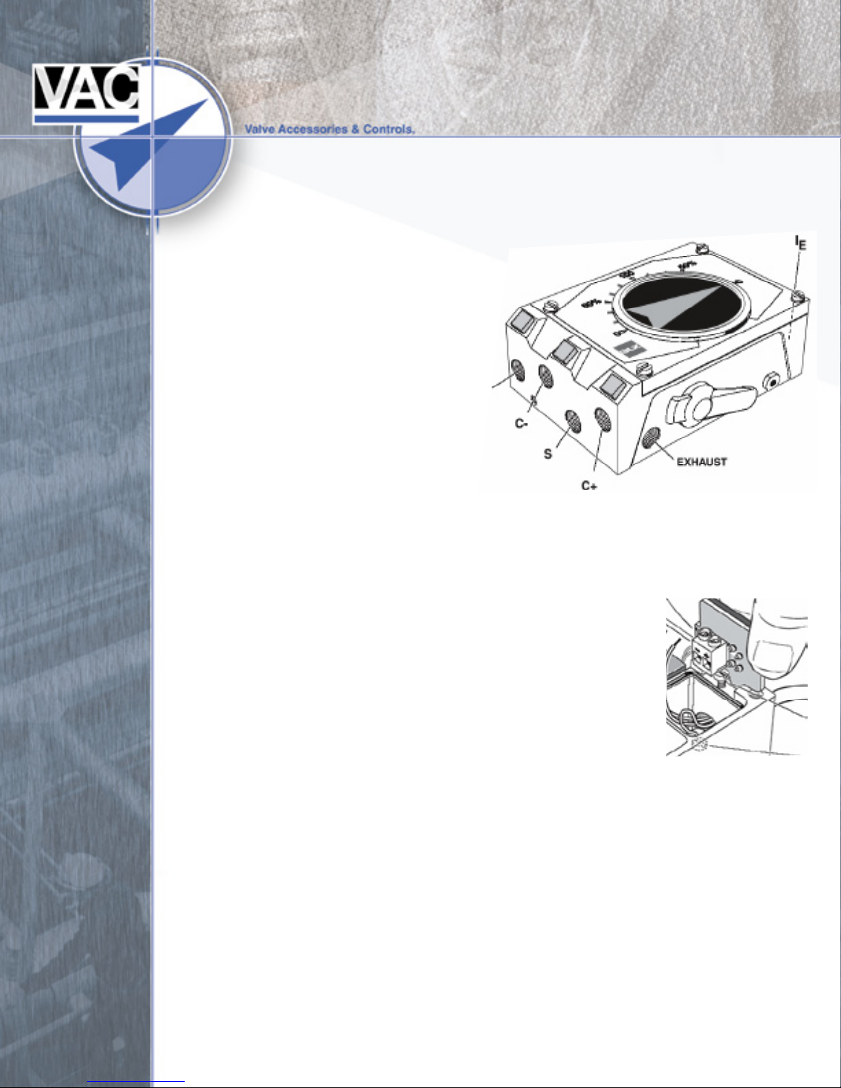
i) Plant Air Supply should be ported to
the Sport on the side of the
positioner. Supply must be
greater than 30 PSI.
ii) The pneumatic control signal
(3 to 15 psi) should be ported to
the Ip port on the side of the
positioner.
If the positioner is a V100E, using
an I/P on the positioner, the Ip
port should be plugged tightly!! Double check once plug is in place to make sure
there is no air leakage from Ip plug.
iii) The driving port of this positioner is the C+ port. In other words, on an
increasing control signal the supply is directed through the positioner to the
C+ port. This is very important – not only for single acting
or spring assist valve packages, but also to insure proper
air to open (or close) operation (rotation).
b) I/P wiring
i) Make sure the unit is properly wired.
(1) The positive terminal (+) MUST have a positive
voltage to it.
(2) The negative terminal (-) MUST have a negative voltage to it.
c) I/P operation
i) If the I/P has been in use the potential for contaminated air
supply exist – check the I/P by either of the following steps.
(1) Install a gauge on the I/P gauge port (1/8 inch NPT) to make
sure that the I/P is generating a 3 to 15 psi pneumatic output in correlation to
the 4 to 20 mA input signal.
(2) Using an ohm meter check to make sure that there is resistance still in the
loop. A good unit will put out 240 Ω or more.
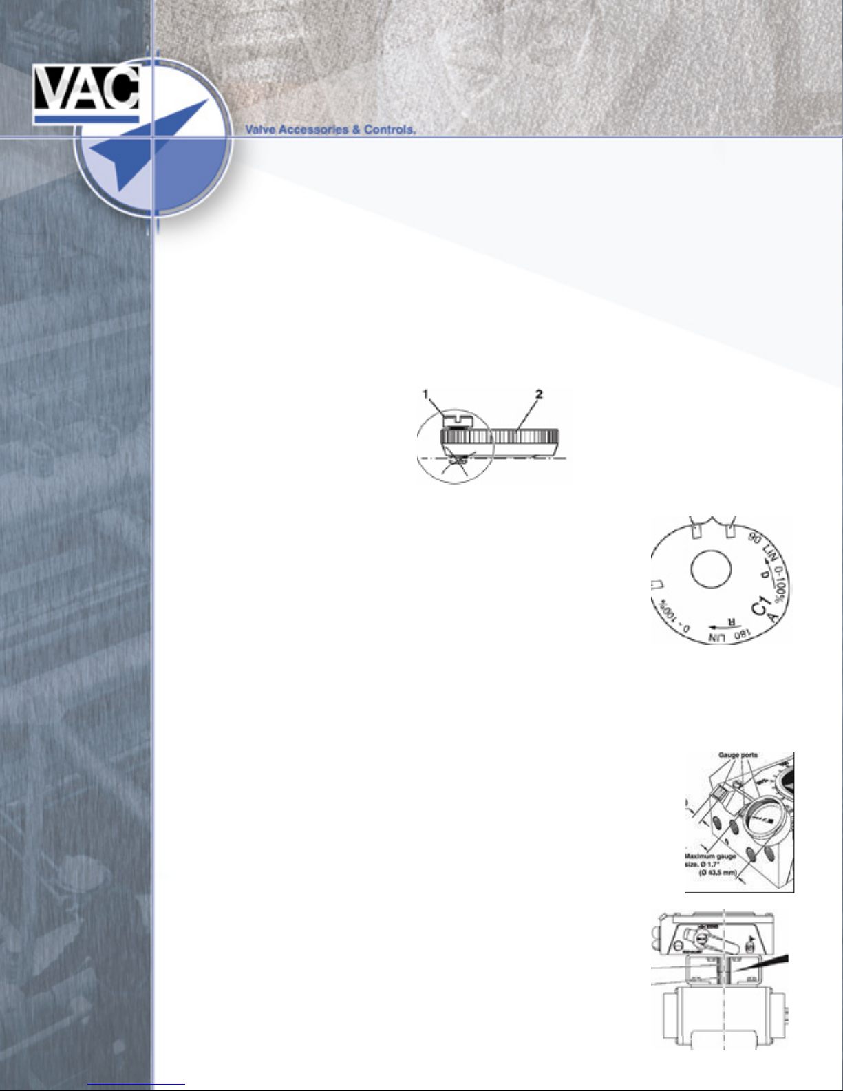
d) Cam
i) If cam nut and locking screw are not correctly inserted the positioner will not work
correctly, generally resulting in the cam slipping and a small input change will
equal a full stroking of the actuator. Make sure that the locking screw is all the
way out before you tighten the cam nut; then secure the locking screw
(the cam nut is the first lock – the screw is the second lock). The cam pictured
below is INCORRECT, and will result in cam slipping and full stroking of the
actuator on small input changes.
ii) Make sure that the Positioner action (direct acting or reverse
acting) corresponds with the cam. A “D” or an “R” can be
found on the cam to indicate direction of cam rotation.
(1) An easy way to check this is to remove the cover of the
positioner and watch the rotation to ensure that cam
placement is correct.
e) Spool Valve
i) Dirty air can cause particulates to cause “sticking” and prevent the positioner
from working correctly. (see below hunting)
(1) Remove the spool valve and blow out with air. If air is not available wipe down with cloth.
Once cleaned the spool piece should slide very easily in its housing. Place spool valve back into
positioner making sure that the slotted top of the spool piece is connected
correctly on the balance arm.
f) Gauge Plugs
i) All gauge plugs or gauges must be secure (no air leaks!!). If the
plugs or gauges are not properly tightened air can leak causing the
positioner not to respond to input signal. Note: gauges are very
useful when trouble shooting a positioner. This helps “inspect” the
air flow through the positioner as well as the I/P output. Three 0-160
psi gauges are used for the supply (S port) and two output ports
(C+ and C-). A 0-30 psi gauge is used for the I/P output.
g) Mounting
i) Rotary
 Loading...