

Page 1
Con guration-, Parameteri zation Ins truc tion C OI/T ZIDC /TZI DC-2 00 -EN
TZIDC, TZIDC-200
Digital Positioner
Software revision 5.0
VALVE ACCESSORIES & CONTROLS
Page 2

2 COI/TZIDC/TZIDC-200- EN | TZIDC, TZIDC- 200
Short product description
Digital positioner for the positioning of pneumatically controlled
actuators.
Device rmware version: 05.00.00
Further information
A
dditional documentation on TZIDC, TZIDC-200 is available to
download free of charge at www.abb.com/positioners.
A
lternatively simply scan this code:
Manufacturer
A
BB Automation Products GmbH
Process Automation
Schillerstr. 72
32425 Minden
Germany
Tel: +49 571 830-0
Fax: +49 571 830-1806
Customer service center
Change from one to two columns
Page 3

TZIDC, TZIDC- 200 | COI/TZIDC/TZIDC-200-EN 3
Contents
1 Safety ............................................................................... 5
1.1 General information and instructions .................... 5
1.2 Warnings ............................................................. 5
1.3 Intended use ........................................................ 5
1.4 Improper use ....................................................... 5
1.5 Warranty provisions ............................................. 5
2 Operatio n ......................................................................... 6
2.1 Safety instru ctions ............................................... 6
2.2 Parameterization of the device ............................. 6
2.2.1 Menu navigation .................................................. 6
2.3 Menu levels .......................................................... 7
2.4 Operating modes ................................................. 7
2.4.1 Operating mode 1.0: Control with adaptation ....... 7
2.4.2 Operating mode 1.1: Control without adaptation .. 7
2.4.3 Operating mode 1.2: Manual adjustment in the
stroke ra nge ........................................................ 8
2.4.4 Operating mode 1.3: Manual adjustment in the
sensor range ........................................................ 8
2.5 Inhibiting operation .............................................. 8
3 Congurat ion ................................................................... 9
3.1 General information .............................................. 9
3.2 Example .............................................................. 9
3.3 HART parameter description .............................. 10
3.4 HART parameter over view (graphic) ................... 12
3.5 Parametergroup 1: Standard ............................. 12
3.5.1 ACTUATOR – Actu ator type ............................... 12
3.5.2 AUTO_ADJ – automatic adjustment ................... 12
3.5.3 ADJ_MODE – Automatic adjustment mode ........ 13
3.5.4 TEST – Te st ....................................................... 14
3.5.5 FIND_DEV – Find device .................................... 14
3.5.6 EXIT – Return to op erating level ......................... 14
3.6 Parameter group 2: Setpoint .............................. 15
3.6.1 MIN_RGE – Setpoint range min. ........................ 15
3.6.2 MAX_RGE – Setpoint range max........................ 15
3.6.3 CHARACT – Character istic curve ....................... 15
3.6.4 ACTION – Direction of action (setpoint signal) ..... 15
3.6.5 SHUT_CLS – Shut-o value 0% ......................... 16
3.6.6 SHUT-OPN – Shut -o value 100%..................... 16
3.6.7 RAMP UP – Setpoint ramp (up) .......................... 16
3.6.8 RAMP DN – Setpoint ramp (down) ..................... 16
3.6.9 EXIT – Return to op erating level ......................... 17
3.7 Parameter group 3: Operating range .................. 17
3.7.1 MIN_RGE – Operatin g range min. ...................... 17
3.7.2 MAX_RGE – Operatin g range ma x. .................... 17
3.7.3 ZERO_POS – Zero position ................................ 18
3.7.4 EXIT – Return to op erating level ......................... 18
3.8 Parameter group 4: Messa ges ........................... 18
3.8.1 TIME_OUT – Dead band time limit ...................... 18
3.8.2 POS_SW1 – Switchin g point SW1 ..................... 18
3.8.3 POS_SW2 – Switchin g point SW2 ..................... 19
3.8.4 SW1_ACTV – Active direction SW1 .................... 19
3.8.5 SW2_ACTV – Active direction SW2 .................... 19
3.8.6 EXIT – Return to op erating level.......................... 19
3.9 Parameter group 5: Alarms ................................ 20
3.9.1 LEAKAGE – Leakage at actuator ........................ 20
3.9.2 SP_RGE – Setpoint monitoring .......................... 20
3.9.3 SENS_RGE – Operatin g range exceeded ........... 20
3.9.4 CTRLER – Contro ller inactive ............................. 20
3.9.5 TIME_OUT – Dead band time limit ...................... 20
3.9.6 STRK_CTR – Moveme nt counter ....................... 20
3.9.7 TRAVEL – Travel counter ................................... 21
3.9.8 EXIT – Return to op erating level.......................... 21
3.10 Parameter group 6: Ma nual adjustment ............. 21
3.10.1 MIN_VR – Operatin g range mi n. ......................... 21
3.10.2 MAX_VR – Operatin g range ma x. ....................... 22
3.10.3 ACTUATOR – Actu ator type ............................... 22
3.10.4 SPRNG_Y2 – Spring action (Y2) ......................... 22
3.10.5 DANG_DN – Dead Angle Close .......................... 23
3.10.6 DANG_UP – Dead Angle Open .......................... 23
3.10.7 BOLT_POS – Actua tor position .......................... 23
3.10.8 EXIT – Return to op erating level.......................... 23
3.11 Parameter group 7: Co ntrol parameters ............. 24
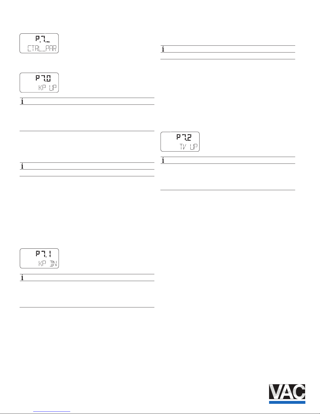
3.11.1 KP UP – KP va lue (up) ....................................... 24
3.11.2 KP DN – KP value (down) ................................... 24
3.11.3 TV UP – TV va lue (up) ........................................ 24
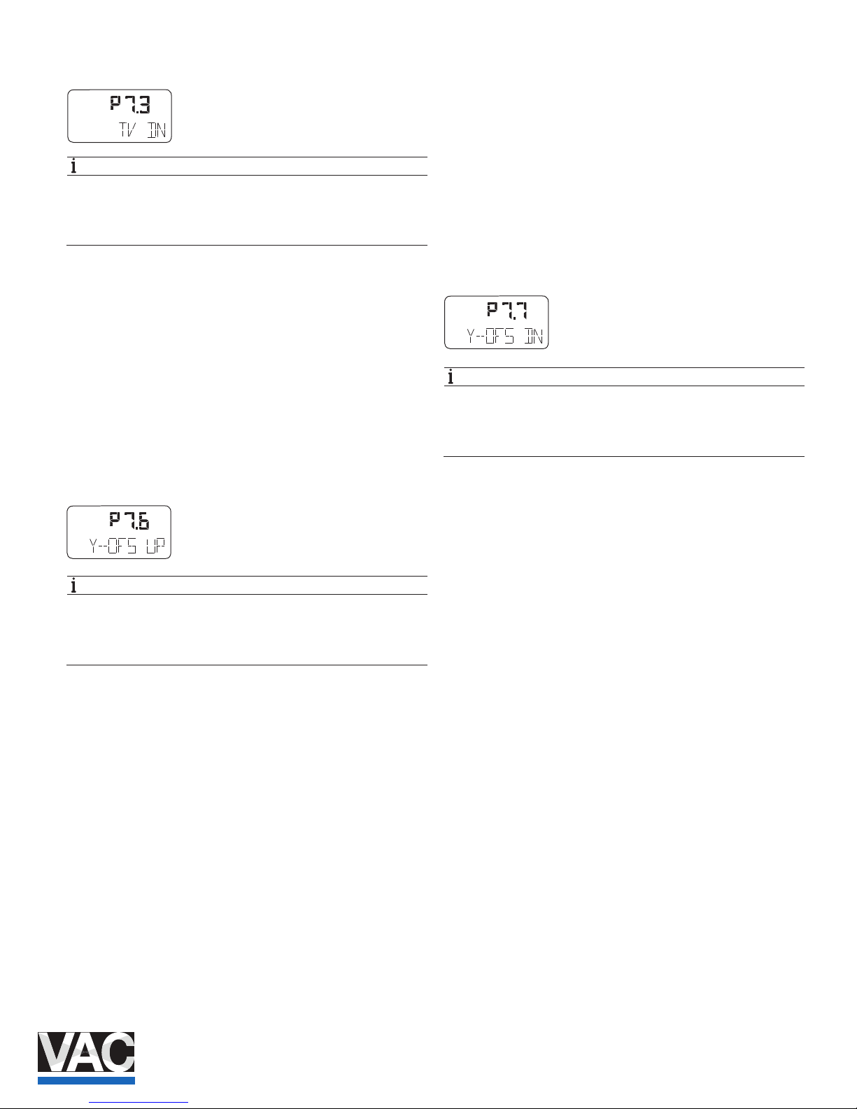
3.11.4 TV DN – TV va lue (down) ................................... 25
3.11.5 Y-OFS UP – Y oset (up) .................................... 25
3.11.6 Y-OFS DN – Os et (down) ................................. 25
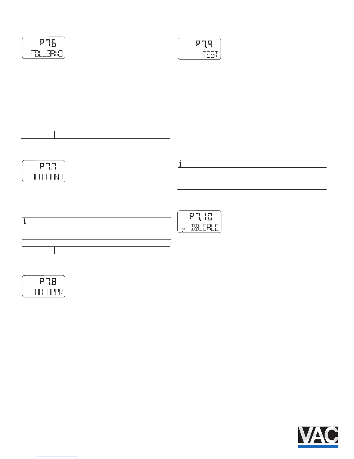
3.11.7 TOL_BAND – Toler ance band ............................ 26
3.11.8 DEADBAND – Dead band .................................. 26
3.11.9 DB_APPR – Dead ba nd approach ..................... 26
3.11.10 DB_CALC – Dead-band determination ............... 26
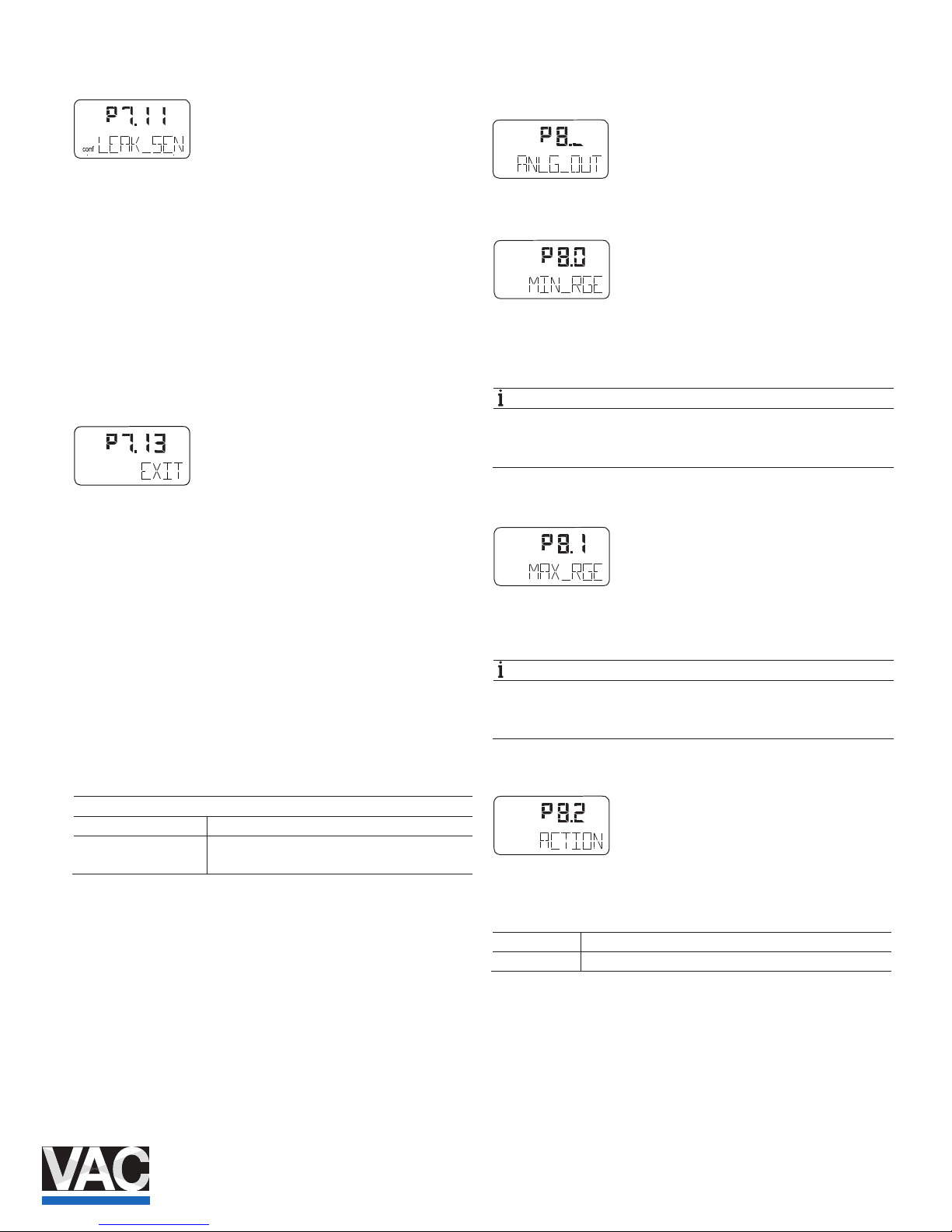
3.11.11 LEAK_SEN – Leakage sensitivity ........................ 27
3.11.12 EXIT – Return to op erating level.......................... 27
3.12 Parameter group 8: Analog output ..................... 27
3.12.1 MIN_RGE – Current range min. .......................... 27
3.12.2 MAX_RGE – Current range max. ........................ 27
3.12.3 ACTION – Characteris tic curve action ................ 27
3.12.4 ALARM – Alarm ................................................. 28
3.12.5 RB_CHAR – Count back characteristic curve ..... 28
3.12.6 TEST – Te st ....................................................... 28
3.12.7 ALR_ENAB – Alarm vi a analog ou tput ................ 28
3.12.8 CLIPPING – Extending the signal output range ... 28
3.12.9 EXIT – Return to op erating level.......................... 28
Page 4

4 COI/TZIDC/TZIDC-200- EN | TZIDC, TZIDC- 200
3.13 Parameter group 9: digital output ....................... 29
3.13.1 ALRM_LOG – Alarm ou tput logic ....................... 29
3.13.2 SW1_LOG – Logic ............................................. 29
3.13.3 SW2_LOG – Logic ............................................. 29
3.13.4 EXIT – Return to op erating level ......................... 29
3.14 Parameter group 10: digital input ....................... 30
3.14.1 FUNCTION – Digital input function selection ....... 30
3.14.2 EXIT – Return to op erating level ......................... 30
3.15 Parameter group 11: Safe positi on ..................... 31
3.15.1 FAIL_POS – Safe position .................................. 31
3.15.2 FACT_SET – Fac tory setting .............................. 31
3.15.3 IP-TYP – Type of the I/P module ........................ 32
3.15.4 IP_COMP – IP Co mpensation ............................ 32
3.15.5 HART_REV – HART versio n ............................... 32
3.15.6 EXIT – Return to op erating level ......................... 32
4 Diagnosis / erro r message s .......................................... 33
4.1 Error codes ........................................................ 33
4.2 Alarm co des ...................................................... 35
4.3 Message co des ................................................. 36
4.4 Error hand ling .................................................... 37
4.4.1 Positioner vibrates ............................................. 37
4.4.2 Positioner without function ................................. 38
Page 5

TZIDC, TZIDC- 200 | COI/TZIDC/TZIDC-200-EN 5
1 Safety
Change from one to two columns
1.1 General information and instructions
These instructions are an impo rtant part of the product and
must be retained for future reference.
Installation, commissioning, and maintenance of the product
may only be performed by trained specialist personnel who
have been authorized by the plant operator accordingly. The
specialist personnel must have read and understood the
manual and must comply with its instructions.
For additional information or if specic problems occur that are
not discussed in these instruct ions, contact the manufacturer.
The content of these instructions is neither part of nor an
amendment to any previous or ex
isting agreement, promise or
legal relationship.
Modications and repairs to the product may only be
performed if expressly permitted by these instructions.
Information and symbols on the product must be observed.
These may not be removed and must be fully legible at all
times.
The operating company must stri ctly observe the applicable
national regulations relating to the installation, function testing,
repair and maintenance of electrical products.
1.2 Warnings
The warnings in these instructio ns are structured as follows:
DANGER
The signal word "DANGER" indicates an imminent danger.
Failure to observe this informat ion will result in death or
severe injury.
WARNING
The signal word "WARNING" in dicates an imminent danger.
Failure to observe this informat ion may result in death or
severe injury.
CAUTION
The signal word "CAUTION" in dicates an imminent danger.
Failure to observe this informat ion may result in minor or
moderate injury.
NOTE
The signal word "NOTE" in dicates useful or important
information about the product.
The signal word "NOTE" is n ot a signal word indicating a
danger to personnel. The signal word "NOTE" can also refer
to material damage.
1.3 Intended use
Positioning of pneumatically controlled actuators; designed for
mounting on linear and part-turn actuators.
The device is designed for use exclusively within the stated
values on the name plate and in the data sheet.
— The maximum operating temperature must not be
exceeded.
— The permissible ambient temperature must not be
exceeded.
— The housing protection ty pe must be observed.
1.4 Improper use
The following are considered to be instances of improper use
of the device:
— For use as a climbing aid, e.g. for mounting purposes
— For use as a support for extern al loads, e.g. as a support
for piping, etc.
— Material application, e.g. by painting over the name plate
or welding/soldering on parts.
— Material removal, e.g. by spot drilling the housing.
1.5 Warranty provisions
Usin
g the device in a manner that does not fall within the
scope of its intended use, disregarding this manual, using
underqualied personnel, or making unauthorized alterations
releases the manufacturer from liability for any resulting
damage. This renders the manufacturer's warranty null and
void.
Page 6
6 COI/TZIDC/TZIDC-200- EN | TZIDC, TZIDC- 200
2 Operation
2.1 Safety instructions
CAUTION
Risk of injury due to incorrect parameter values!
Incorrect parameter values can cause the valve to move
unexpectedly. This can lead to process failures and result in
injuries.
— Before recommissioning a positioner that was previously
in use at another location, always reset the device to its
factory settings.
— Never start Auto Adjust before restoring the factory
settings.
If there is a chance that safe op eration is no lo nger possible,
take the device out of operation and secure it against
unintended startup.
2.2 Parameterization of the device
The LCD display features operat ing buttons which enable the
device to be operated with the housing cover open.
2.2.1 Menu navigation
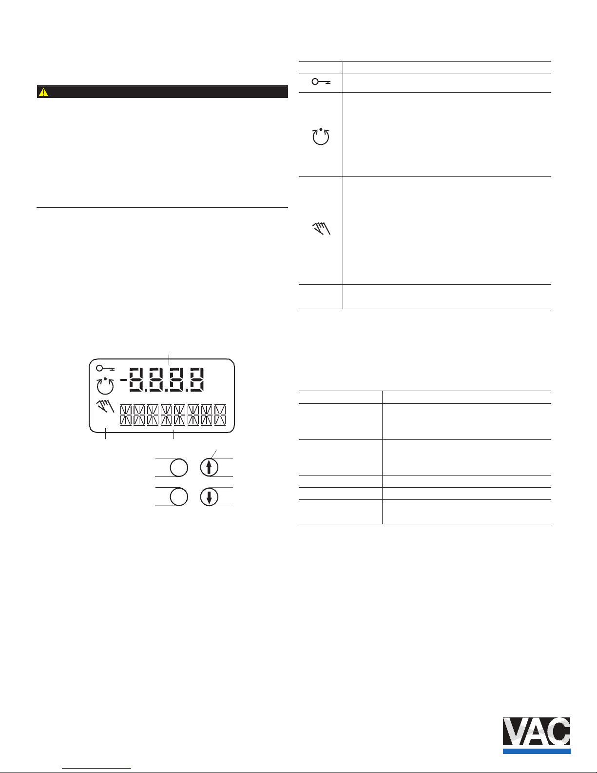
Fig. 1: LCD display with operating buttons
1 Value display with unit 2 Symbol display
3 Designator display 4 Operating buttons for menu navigation
Value display with unit
This 7-segment display with four digits indicates parameter
values or parameter reference numbers. For values, the
physical unit (°C, %, mA) is also displayed.
Designator display
This 14-segment display with eigh
t digits indicates the
designators of the parameters with their status, of the
parameter groups, and of the operating modes.
Description of symbols
Symbol Description
Operation or access is restricted.
Control loop is active.
The symbol is displayed when the positioner is in operating
mode 1.0 CTRL_ADP (adaptive control) or 1.1 CTRL_FIX
(xed control) at operating level. On the conguration level
there are test functions for which the controller will be active
as well. The control loop symbol will also be displayed when
these functions are active.
Manual adjustment.
The symbol is displayed when the positioner is in operating
mode 1.2 MANUAL (manual adjustment within the stroke
range) or 1.3 MAN_SENS (manual adjustment within the
measuring range) at operating level. At conguration level,
manual adjustment is active when setting the valve range
limits (parameter group 6 MIN_VR (min. of valve range) and
6 MAX_VR (max. of valve range)). The symbol will also be
displayed when these parameters are being set.
The conguration icon indicates that the positioner is at the
conguration level. The control operation is inactive.
The four operating buttons ENTER , MODE , and are
pressed individually or in cer tain combinations according to
the function desired.
Operating button functions
Control button
Meaning
ENTER — Acknowledge message
— Start an action
— Save in the non-volatile memory
MODE — Choose operating mode (operating level)
— Select parameter group or parameter
(conguration level)
nottub noitcerid PU
nottub noitcerid NWOD
Press and hold all four
buttons for 5 s
Reset
M10980
conf
mA
%
C
o
E
M
4
1
2
3
conf
Page 7
TZIDC, TZIDC- 200 | COI/TZIDC/TZIDC-200-EN 7
2.3 Menu levels
The positioner has two operating levels:
Operating level
On the operating level the positioner operates in
one of four possible operating modes (two for
automatic control and tw o for manual mode).
Parameters cannot be changed or saved on this
level.
Conguration level
On this level most of the parameters of the
positioner can be changed locally. The PC is
required to change the limit values for the
movement counter, the travel counter, and the
user-dened characteristic curve.
On the conguration level the active operating
mode is deactivated. The I/P module is in neutral
position. The control operation is inactive.
NOTE
Property damage
During external conguration via a PC, the positioner no
longer responds to the setpoi nt current. This may lead to
process failures. Prior to extern al conguration, always move
the actuator to the safety position and activate manual
adjustment.
2.4 Operating modes
2.4.1 Operating mode 1.0: Control with adaptation
Controlling operation with automatic adaptation of the
control parameters
When the P1.0CTRL_ADP positioner is operated in "Adaptive
Mode", the control parameters are automatically optimized to
the operating conditions in small increments. This is especially
helpful if valves and ttings could not be operated with
reference conditions while the Auto Adjust function was in
progress.
Since self-optimization in "A daptive Mode" is subject to
several factors during operatio n and mismatches could result
over a longer period, we recommend that this operating mode
only be activated over severa l hours and be followed by the
mode P1.1 CTRL_FIX .
The valve position is indicated as a percentage of the
operating range (from 0 ... 100%).
2.4.2 Operating mode 1.1: Control without adaptation
Controlling operation with xed parameters
This is the normal recommended operating mode.
In contrast to the operating mode P1.0 CTRL_ADP , the
control parameters are not automatically adjusted.
The valve position is indicated as a percentage of the
operating range (from 0 ... 100%).
In both control modes 1.0 and 1.1 , several values can be
displayed besides the current actuator position:
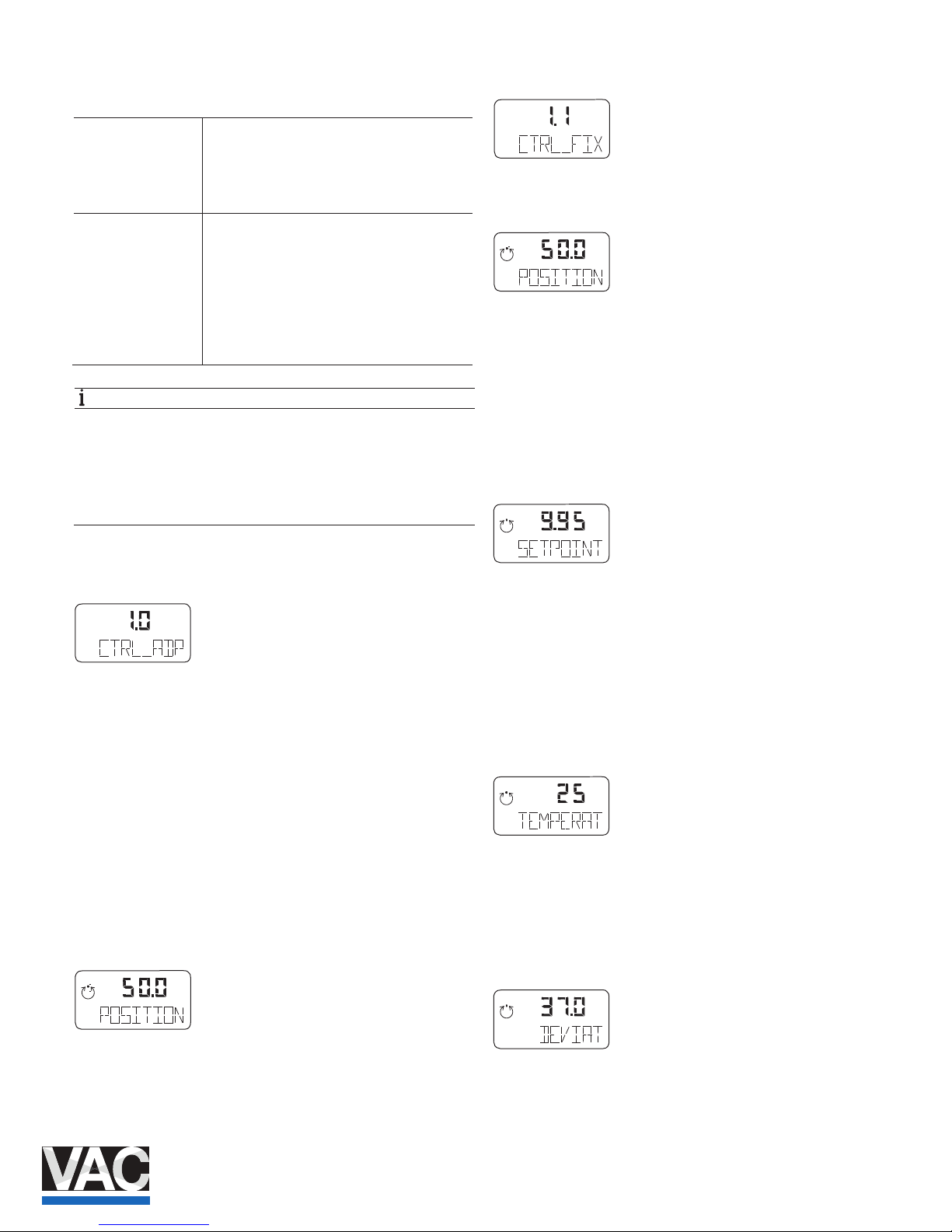
Setpoint display
1. Press and hold the button.
The setpoint is displayed.
2. Briey press ENTER .
The setpoint display is toggled between the setpoint current at
the input terminals i
n mA and the setpoint as a percentage of
the stroke range.
Temperature display
1. Press and hold the button.
The temperature inside the case is displayed.
2. Briey press ENTER .
3. The temperature display is toggled between °C and °F.
Display of control deviation
1. Press and hold the and button.
The control deviation is displayed as a percentage (%) of the
stroke range.
conf
mA
%
C
°
conf
mA
%
C
°
conf
mA
%
C
°
conf
mA
%
C
°
conf
mA
%
C
°
conf
mA
%
C
°
conf
mA
%
C
°
Page 8

8 COI/TZIDC/TZIDC-200- EN | TZIDC, TZIDC- 200
2.4.3 Operating mode 1.2: Manual adjustment in the
stroke range
The valve is adjusted manually using the direction buttons
and within the stroke range.
1. Press and hold the button for the desired direction.
2. To activate the high speed mode in the manual mode,
press the second arrow button.
CAUTION
If air escapes due to a leakag e, the position will not be
readjusted.
Congured stroke limit positions and stroke times are not
eective in manual mode.
In this operating mode the valv e position is indicated as a
percentage (%) of the stroke range.
2.4.4 Operating mode 1.3: Manual adjustment in the
sensor range
See operating mode 1.2
Unlike step 1.2, this operating mode is used to determine
whether the available detection ra nge of the position sensor is
used correctly after mounting the positioner to the actuator. In
this mode, the valve position is indicated in angular degrees
with respect to the sensor range (i.e.,0 ... 140 °).
2.5 Inhibiting operation
Positioner operation can be inhibited completely or partially via
the digital input and the FUNCTION parameter in parameter
gro
up 10 ( DIG_IN (digital input)).
This allows the user to prevent or restrict operating actions of
unauthorized personnel as desired. When operation is
disabled in this way, the key symb ol is indicated in the display.
The following levels of conf iguration locks are possible:
Inhibiting the local conguration
Local operation on the operating level and remote operation
and conguration via a PC are still possible.
Inhibiting all local operating functions
No local operating actions can be executed. Both the
operating level and the conguration level are locked. Remote
operation and setting of parameters via a PC is still possible.
Inhibiting local operation and remote conguration
It is not possible to operate or congure the positioner locally
or congure it using a PC.
NOTE
This inhibit function can only be deactivated when a voltage
of 12 ... 24 V is applied at the digital input of the positioner
(see Function selection in parameter group 10 on page 30).
conf
mA
%
C
°
conf
mA
%
C
°
conf
mA
%
C
°
conf
mA
%
C
°
Page 9
TZIDC, TZIDC- 200 | COI/TZIDC/TZIDC-200-EN 9
3 Conguration
3.1 General information
Most parameters for the position er can be set locally, meaning
that conguration only needs to be performed via the local
communication interface (LCI) or FSK modem and PC in
exceptional cases.
You may also deny or restrict local modication and saving of
parameters by completely or partially blocking access to the
conguration level (see Chapter "Inhibiting operation" on page
8 and the description of the Function parameter on page 30).
To simplify the process, the di erent parameters are grouped
as follows:
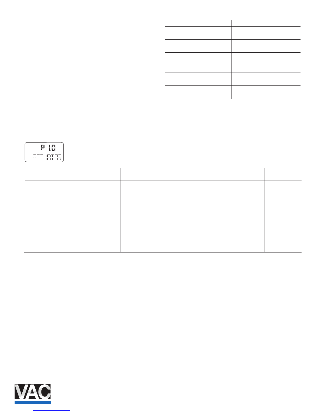
ID Designator Name
P1._ STANDARD Standard
P2._ SETPOINT Setpoint
P3._ ACTUATOR Actuator
P4._ MESSAGES Events
P5._ ALARMS Alarms
P6._ MAN_ADJ Manual adjustment
P7._ CTRL_PAR Control parameters
P8._ ANLG_OUT Analog output
P9._ DIG_OUT Digital output
P10._ DIG_IN Digital input
P11._ FS / IP Factory setting, I/P type
The following sections provide an overview (in tabular and
graphical format) of the overa ll structure of the parameter
groups and parameters.
Change from two to one column
3.2 Example
Parameter (1st line in
display)
Indicator (2nd line in
display)
Function Possible parameter settings Unit Factory Setting
P1._ STANDARD
P1.0 ACTUATOR Actuator type LINEAR, ROTARY - LINEAR
P1.1 AUTO_ADJ Autoadjust Command / Function is being
run
- -
P1.2 ADJ_MODE Automatic adjustment mode FULL, STROKE, CTRL, PAR,
ZERO_POS, LOCKED
- FULL
P1.3 TEST gnieb si noitcnuF / dnammoC tseT
run
- INACTIV
P1.4 EXIT Return to operating level Command / Function is being
run
- NV_SAVE
P2._ SETPOINT
conf
Page 10

10 COI/TZIDC/TZIDC-200- EN | TZI DC, TZIDC-200
3.3 HART parameter description
Parame
ter
Display Function Possible parameter setting Unit Factory setting
P1._ STANDARD
P1.0 ACTUATOR RAENIL --- YRATOR ,RAENIL epyt rotautcA epyt rotautcA
P1.1 AUTO_ADJ --- --- noitcnuF tsujdaotuA tsujda otuA
P1.2 ADJ_MODE Auto adjust mode Automatic adjustment mode FULL,STROKE,CTRL_PAR, ZERO_POS,
LOCKED
FULL
P1.3 TEST EVITCANI --- noitcnuF tseT tseT
P1.4 FIND_DEV Find device Find device DISABLE, ONE TIME, CONTINOUS --- DISABLE
P1.5 EXIT EVAS_VN --- noitcnuF level gnitarepo ot nruteR nruteR
P2._ SETPOINT
P2.0 MIN_RGE 0.4 Am 4.81 … 0.4 egnar tnioptes .niM egnar tnioptes niM
P2.1 MAX_RGE 0.02 Am 6.5 … 0.02 egnar tnioptes .xaM egnar tnioptes xaM
P2.2 CHARACT Charact. curve Characteristic curve LINEAR, 1:25, 1:50, 25:1, 50:1, USERD --- LINEAR
P2.3 ACTION Valve action Eective directio TCERID --- ESREVER ,TCERID n
P2.4 SHUT_CLS 0.1 % 0.54 … 1.0 ,FFO % 0 eulav ffo-tuhS %0 eulav ffo-tuhS
P2.5 SHUT_OPN Shut o value 100% Shut-o FFO % FFO ,0.001 … 0.55 % 001 eulav
P2.6 RAMP UP Set point ramp, up Setpoint ra FFO --- 002 … 0 ,FFO )pu( pm
P2.7 RAMP DN FFO --- 002 … 0 ,FFO )nwod( pmar tniopteS nwod ,pmar tniop teS
P2.8 EXIT EVAS_VN --- noitcnuF level gnitarepo ot nruteR nruteR
P3._ ACTUATOR
P3.0 MIN_RGE 0.0 % 0.09 … 0.0 .nim ,egnar gnitarepO egnar ekorts fo .niM
P3.1 MAX_RGE 001 % 0.01 … 0.001 .xam ,egnar gnitarepO egnar ekorts fo .xaM
P3.2 ZERO_POS Zero position Zero position CLOC KWISE, CTCLOCKWISE --- CTCLOCKWISE
P3.3 EXIT EVAS_VN --- noitcnuF level gnitarepo ot nruteR nruteR
P4._ MESSAGES
P4.0 TIME_OUT Control time out Dead FFO --- 002 … ,FFO timil emit dnab
P4.1 POS_SW1 Position switch 1 0.0 % 0.001 … 0.0 1WS tniop gnihctiwS
P4.2 POS_SW2 Position switch 2 0.001 % 0.001 … 0.0 2WS tniop gnihctiwS
P4.3 SW1_ACTV LEB_LLAF --- DEECXE ,LEB_LLAF 1WS noitcerid evitcA elbane 1 tniophctiwS
P4.4 SW2_ACTV DEECXE --- DEECXE ,LEB_LLAF 2WS noitcerid evitcA elbane 2 tniophctiwS
P4.5 EXIT EVAS_VN --- noitcnuF level gnitarepo ot nruteR nruteR
P5._ ALARMS
P5.0 LEAKAGE EVITCANI --- EVITCANI ,EVITCA rotautca ot egakaeL noitceted egakaeL
P5.1 SP_RGE EVITCANI --- EVITCANI ,EVITCA egnar tnioptes eht edistuO rotinom gnr tniopteS
P5.2 SENS_RGE EVITCANI --- EVITCANI ,EVITCA dedeecxe egnar gnitarepO rotinom egnar .sneS
P5.3 CTRLER Controller monitor Controller inactive ACTIVE, INACTI EVITCANI --- EV
P5.4 TIME_OUT EVITCANI --- EVITCANI ,EVITCA timil emit dnab daeD tuo emit lortnoC
P5.5 STRK_CTR Stroke counter Movement counter ACTIVE, INACTIVE EVITCANI ---
P5.6 TRAVEL EVITCANI --- EVITCANI ,EVITCA retnuoc levarT retnuoc levarT
P5.7 EXIT EVAS_VN --- noitcnuF level gnitarepo ot nruteR nruteR
P6._ MAN_ADJ
P6.0 MIN_VR 0 % 0.001 … 0.0 .nim ,egnar gnitarepO egnar evlav .niM
P6.1 MAX_VR 001 % 0.001 … 0.0 .xam ,egnar gnitarepO egnar evlav .xaM
P6.2 ACTUATOR RAENIL --- YRATOR ,RAENIL epyt rotautcA epyt rotautcA
P6.3 SPRNG_Y2 Spring action (Y2) Spring action (Y2) CL OCKWISE, CTCLOCKWISE --- CTCLOCKWISE
P6.4 DANG_DN 0.0 % 0.54 … 0.0 % 0 elgna daeD esolc elgna daeD
P6.5 DANG_UP 0.001 % 0.001 … 0.55 % 001 elgna daeD nepo elgna daeD
P6.6 BOLT_POS REVEL --- METS ,REVEL noitisop rotautcA noitisop tloB
P6.7 EXIT EVAS_VN --- noitcnuF level gnitarepo ot nruteR nruteR
Page 11
TZIDC, TZIDC- 200 | COI/TZIDC/TZIDC-200-EN 11
Parame
ter
Display Function Possible parameter setting Unit Factory setting
P7._ CTRL_PAR
P7.0 KP UP 0.5 --- 0.021 … 1.0 )pu( eulav PK pu ,eulav PK
P7.1 KP DN 0.5 --- 0.021 … 1.0 )nwod( eulav PK nwod ,eulav PK
P7.2 TV UP TV value, up TV value 002 --- 054 ... 01 )pu(
P7.3 TV DN 002 --- 054 ... 01 )nwod( eulav VT nwod ,eulav VT
P7.4 Y-OFS UP 0.84 % 0.001 … 0.0 )pu( tesffo Y pu ,tesffo Y
P7.5 Y-OFS DN 0.84 % 0.001 … 0.0 )nwod( tesffo Y nwod ,tesffo Y
P7.6 TOL_BAND 5.1 % 0.01 … 3.0 )enoz( dnab ecnareloT )enoz( dnab ecnareloT
P7.7 DEADBAND 01.0 % 00.01 … 01.0 dnab daeD dnabdaeD
P7.8 DB_APPR Deadband Approach Dead-band ap TSAF ,MUIDEM ,WOLS hcaorp
P7.9 TEST EVITCANI --- noitcnuF tseT tseT
P7.10 DB_CALC NO --- FFO ,NO noitanimreted dnab-daeD .taluclac dnabdaeD
P7.11 LEAK_SEN Leakage sensivity Leakag 03 S 0027 … 1 ytivitisnes e
P7.12 CLOSE_UP Pos. time out Po 0.03 % 0.001 … 0.0 gnirotinom noitis
P7.13 EXIT EVAS_VN --- noitcnuF level gnitarepo ot nruteR nruteR
P8._ ANLG_OUT
P8.0 MIN_RGE 0.4 Am 4.81 … 0.4 egnar tnerruc .niM egnar .niM
P8.1 MAX_RGE 0.02 Am 7.5 … 0.02 egnar tnerruc .xaM egnar .xaM
P8.2 ACTION Action Direction of action of
characteristic curve
TCERID --- ESREVER ,TCERID
P8.3 ALARM Alarm current Alarm message HI RUC_HGIH --- RUC_WOL ,RUC_HG
P8.4 RB_CHAR TCERID CLACER ,TCERID sretcarahc detrevnoC .retcarahc kcabdaeR
P8.5 TEST ENON --- noitcnuF tseT tseT
P8.6 ALR_ENAB NO --- FFO ,NO tuptuo golana aiv mralA delbane noitcnuf mralA
P8.7 CLIPPING Current signal
Signal clipping range
Extension of signal output to
3.8 … 20.5 mA
4.0 … 20.0; 3.8 … 20.5 mA mA 4.0 … 20.5
P8.8 EXIT --- --- noitcnuF level gnitarepo ot nruteR nruteR
P9._ DIG_OUT
P9.0 ALRM_LOG Alarm logic Alarm output logic ACTIVE_HI, ACTIVE_LO --- ACTIVE_HI
P9.1 SW1_LOG Switchpoint 1 logic Logic SW1 ACTIVE_HI, ACTIVE_LO --- ACTIVE_HI
P9.2 SW2_LOG Switchpoint 2 logic Logic SW2 ACTIVE_HI, ACTIVE_LO --- ACTIVE_HI
P9.3 TEST ENON --- noitcnuF tseT tseT
P9.4 EXIT EVAS_VN --- noitcnuF level gnitarepo ot nruteR nruteR
P10._ DIG_IN
P10.0 FUNCTION Function select Function selection NONE, POS_0 %, POS_100 %, POS_HOLD --- NONE
P10.1 EXIT --- --- noitcnuF level gnitarepo ot nruteR nruteR
P11._ FS / IP
P11.0 FAIL_POS EVITCANI --- EVITCANI ,EVITCA noitisop efaS noitisop evaS
P11.1 FACT_SET TRATS --- noitcnuF gnitteS yrotcaF gnittes yrotcaF
P11.2 IP-TYP I/P module type Type of l/P mo dule NO_F_POS,F_SAFE_1,F_SAFE_2,
F_FREEZE1, F_FREEZE2
--- [CUSTOM]
P11.3
1)
IP_COMP NO --- FFO ,NO noitasnepmoc PI noitasnepmoc PI
P11.4 HART_REV 5 --- 7 ;5 noisiveR TRAH noisiver TRAH
P11.5 EXIT EVAS_VN --- noitcnuF level gnitarepo ot nruteR nruteR
1) Activation only by A BB Service
Page 12

12 COI/TZIDC/TZIDC-200- EN | TZI DC, TZIDC-200
3.4 HART parameter overview (graphic)
Fig. 2
Change from one to two columns
3.5 Parametergroup 1: Standard
3.5.1 ACTUATOR – Actuator type
With this parameter you can congure the positioner for
operation on a linear actuator (sensor range ±30°) or on a
part-turn actuator (sensor ra nge ±45°). No mechanical
modications to the positioner are required.
NOTE
After changing the actuator type , it is recommended that you
run automatic adjustment to prevent linearity errors.
Selection
LINEAR Linear actuator
ROTARY Part-turn actuator
3.5.2 AUTO_ADJ – automatic adjustment
The following values are determined during Auto Adjust:
— Direction of action of the actuator
— Direction of action of the reset spring
— Actuator travel of the multi-turn actuator / nal control
element
— Stroke time for both directions
— Control parameters
— Oset for the I/P module
NOTE
The mode and scope of the automatic adjustment function
can be selected using parameter
A
DJ_MODE .
M10487
I.3
conf
mA
%
C
°
conf conf con f conf conf conf conf con f conf
ENTER
MODE
ENTER
(3 ... 0)
(3 ... 0)
conf
I.0
CTRL_ADP
CTRL_FIX
I.2
MANUAL
MAN_SENS
I.I
ENTER
Parameter “EXIT”
(NV_SAVE)
P1.0
P1.1
P1.2
P1.3
P1.4
P1.5
P4.0
P4.1
P4.2
P4.3
P4.4
P4.5
P2.0
P2.1
P2.2
P2.3
P2.4
P2.5
P2.6
P2.7
P2.8
P3.0
P3.1
P3.2
P3.3
P5.0
P5.1
P5.2
P5.3
P5.4
P5.5
P5.6
P5.7
P6.0
P6.1
P6.2
P6.3
P6.4
P6.5
P6.6
P6.7
P7.0
P7.1
P7.2
P7.3
P7.4
P7.5
P7.6
P7.7
P7.8
P7.9
P7.10
P7.11
P7.12
P8.0
P8.1
P8.2
P8.3
P8.4
P8.5
P8.6
P8.7
P8.8
P9.0
P9.1
P9.2
P9.3
P9.4
P10.0
P10.1
P11.0
P11.1
P11.2
P11.3
P11.4
P11.5
conf
conf
conf
P1._
STANDARD
P2._
SETPOINT
P3._
ACTUATOR
P4._
MES
P5._
ALARMS
P6._
MAN_ADJ
P7._
CTRL_PAR
P8._
ANLG_OUT
P9._
DIG_OUT
P10._
DIG_IN
P11._
FS/IP
MODE
MODE
Configuration level
Operating level
P7.13
conf
conf
conf
mA
%
C
°
Page 13
TZIDC, TZIDC- 200 | COI/TZIDC/TZIDC-200-EN 13
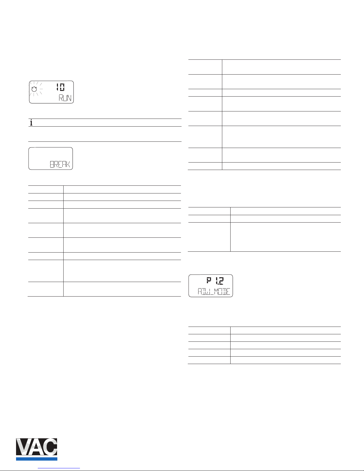
To start the automatic adjustment, press and hold ENTER
until the countdown from 3 to 0 is nished. During the
countdown, the automatic adjust ment mode selected using
parameter ADJ_MODE is shown on the display. While
Autoadjust is running, the control loop symbol ashes in the
display, and the current state of Autoadjust is indicated with
the messages listed below.
(No acknowledgment)
NOTE
All messages except "RUN" mu st be acknowledged with
ENTER .
(Acknowledgment required)
RUN
Autoadjust is running.
CALC_ERR Error during plau sibility check.
COMPLETE
Autoadjust completed successfully.
BREAK
Autoadjust has been stopped by the operator. This can
be done locally by pressing ENTE R .
OUTOFRNG
Sensor range of the positioner has been exceeded;
Autoadjust was stopped.
NO_SCALE
End positions have not yet been determined; therefore,
partial Autoadjust cannot be run
RNG_ERR
Less than 10% of the sensor range is used.
TIMEOUT
Timeout. The control parameters could not be
determined within 200 second s. Automatic adjustment
was stopped.
SPR_ERR
The actual spring action does not match the congured
spring action
Once Autoadjust has nished running without encountering
any errors, the device displays the message "RUN" in the
bottom line and a code number in the top line, indicating the
step that is currently being executed:
10 Air is completely evacuated from actuator (OUT1). The
fully evacuated position is saved.
20 Air is completely ventilated from actuator (OUT1). The
fully ventilated position is saved.
30 Determining stroke time is prepared.
31 Actuator travels from 0% to 100%, stroke time is
measured and saved.
32 Actuator travels from 100% to 0%, stroke time is
measured and saved.
40 - 49 Tolerance band is determined and saved (minimum
value). PD parameters for fast control < tolerance band
is determined and saved.
50 - 59 PID parameters for fast control < tolerance band is
determined and saved.
200 Automatic adjustment is complete.
If a partial run of automatic adjustment has been selected (see
parameter DANG_DN on page 23), the following code
numbers are shown:
Stops only Steps 10 … 32 and step 200
Parameters only Steps 40 … 120 and step 200
Zero only:
10 Air is completely evacuated from actuator (OUT1).
The fully evacuated position is saved.
200 Automatic adjustment is complete.
3.5.3 ADJ_MODE – Automatic adjustment mode
Use this parameter to dene the mode or scope of the Auto
Adjust function.
FULL Complete Autoadjust
STROKE Stops only
CTRL_PAR Control parameters only
ZERO_POS Zero position only (con gured stops required)
LOCKED No Autoadjust
conf
mA
%
C
°
con f
conf
mA
%
C
°
Page 14
14 COI/TZIDC/TZIDC-200- EN | TZI DC, TZIDC-200
3.5.4 TEST – Test
The test is used to activate th e positioner, and you can check
the eects of the changes to this parameter group, e.g., by
introducing setpoint changes or setpoint ramps using a
current source.
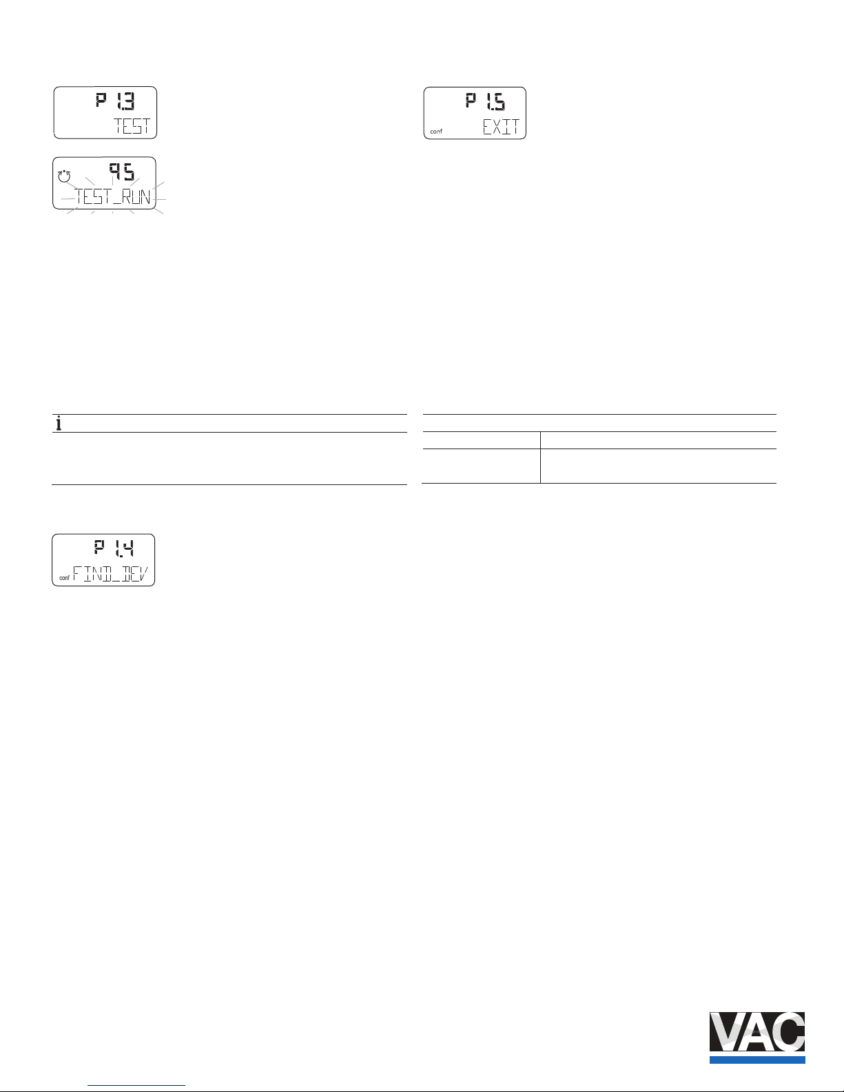
Normally, INACTIVE is shown in the display. To start the test,
press and hold ENTER until the countdown from 3 to 0 is
nished. The test is activated . The display shows the control
loop symbol and a ashing message. The test is automatically
stopped after two minutes and can also be stopped by
pressing any button.
NOTE
It is not possible to start the te st when the safe position is
active (see the FAIL_POS parameter on page 31.) Instead,
the message FAIL_POS is displayed.
3.5.5 FIND_DEV – Find device
This function is only possible with HART 7 and enables
identication of the aected device in the system.
Following activation, the device sends a signal on request
under HART 7. The following signals are available:
— Disable
— One time
— Continuous
3.5.6 EXIT – Return to operating level
With this parameter you can leave the conguration level. The
positioner returns to the operating level. Here you can either
save data in the non-volatile me mory or discard all previously
made changes (also the changes in other parameter groups).
To leave the conguration level (with or without saving), press
and hold ENTER until the countdown from 3 to 0 is nished.
The active s
aving process is indicated by the message
NV_SAVE . After saving a plausibility check is executed.
If an error occurs during the check or while saving, the data
cannot be saved and an error message is displayed instead
(see Chapter "Error codes" on page 33).
Selection
NV_SAVE Saves settings in the non-volatile memory.
CANCEL Discards all changes made since the last
permanent save operation.
conf
%
conf
mA
%
C
°
Page 15
TZIDC, TZIDC- 200 | COI/TZIDC/TZIDC-200-EN 15
3.6 Parameter group 2: Setpoint
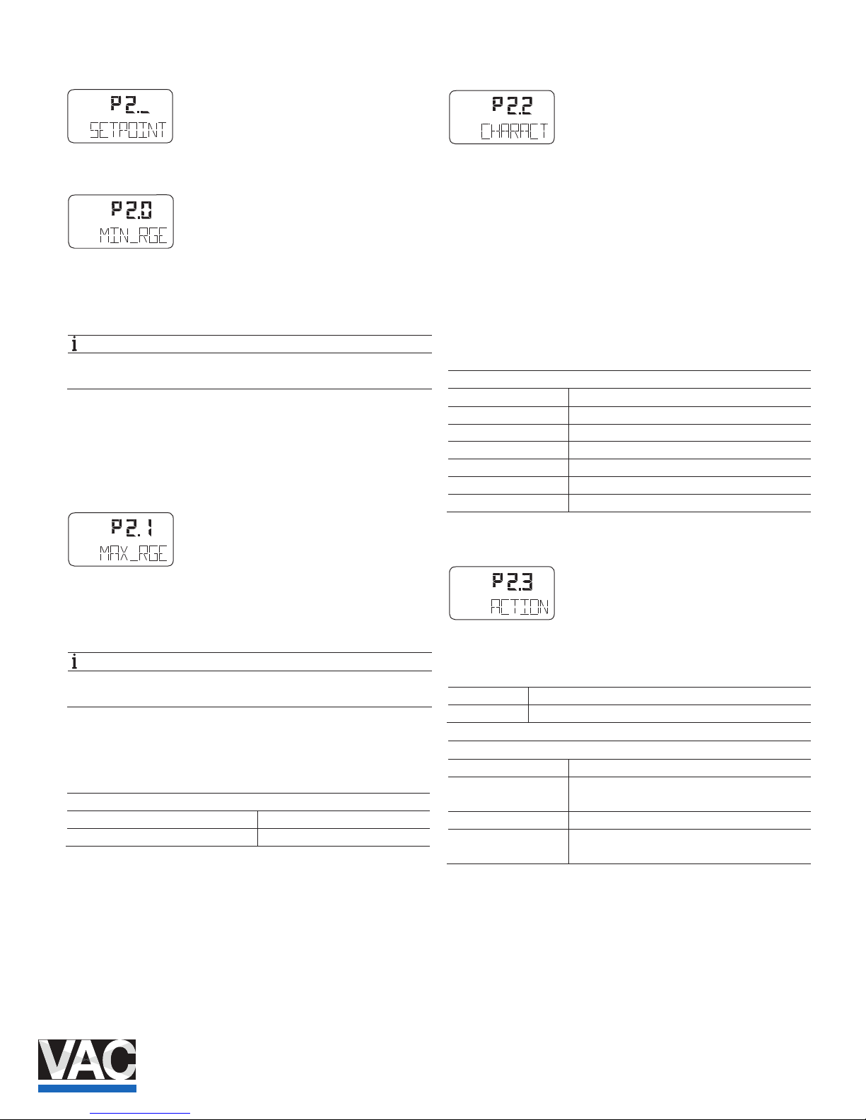
3.6.1 MIN_RGE – Setpoint range min.
The setpoint range is the input current range as a percentage
of the working range for the valves and ttings (from
0 ... 100 %).
NOTE
The congured setpoint range must not be smaller than
20 % (3.2 mA).
Use the MIN_RGE parameter to determine the lower limit of
the setpoint range. You can ente r a value within the admissible
value range of 4 ... 18.4 mA, with one decimal.
3.6.2 MAX_RGE – Setpoint range max.
The setpoint range is the input current range as a percentage
of the working range for the valves and ttings (from
0 ... 100 %).
NOTE
The congured setpoint range must not be smaller than
20 % (3.2 mA).
Use the MAX_RGE parameter to determine the upper limit of
the setpoint range. You can ente r a value within the admissible
value range of 5.6 ... 20 mA, with one decimal.
Setting examples
Setpoint Range Min. = 8.3 mA, Max. = 15.6 mA
Split range conguration between Min. = 12.0 mA, Max. = 20.0 mA
3.6.3 CHARACT – Characteristic curve
Use this parameter to select a function that adjusts the
behavior of the positioner to the analog input signal according
to a predened course.
This linearizes the characteristi c curves for the valves and
ttings and improves the behavior of the overall control loop.
In addition to ve predened characteristic curves, you can
also select a user-congurable characteristic curve, which can
only be generated and saved in the device via a PC with the
appropriate conguration program (and not locally).
Selection
LINEAR Linear
EP 1/25 equal percentage 1:25
EP 1/50 equal percentage 1:50
EP 25/1 equal percentage 25:1
EP 50/1 equal percentage 50:1
USERDEF congurable by user
USERDEF LINEAR
3.6.4 ACTION – Direction of action (setpoint signal)
The direction of action describes the relationship between the
analog setpoint and pneumatic output OUT1 .
Increasing Setpoint 0 ... 100 % Output 0 ... 100 %
Decreasing Setpoint 0 ... 100 % Output 100 ... 0 %
Selection
DIRECT Increasing
Control signal 4 ... 20 mA, and
setpoint 0 ... 100 % = position 0 ... 100 %
REVERSE Decreasing
Control signal 20 ... 4 mA, and
setpoint 100 ... 0 % = position 0 ... 100 %
conf
conf
conf
mA
%
C
°
conf
mA
%
C
°
conf
mA
%
C
°
Page 16
16 COI/TZIDC/TZIDC-200- EN | TZI DC, TZIDC-200
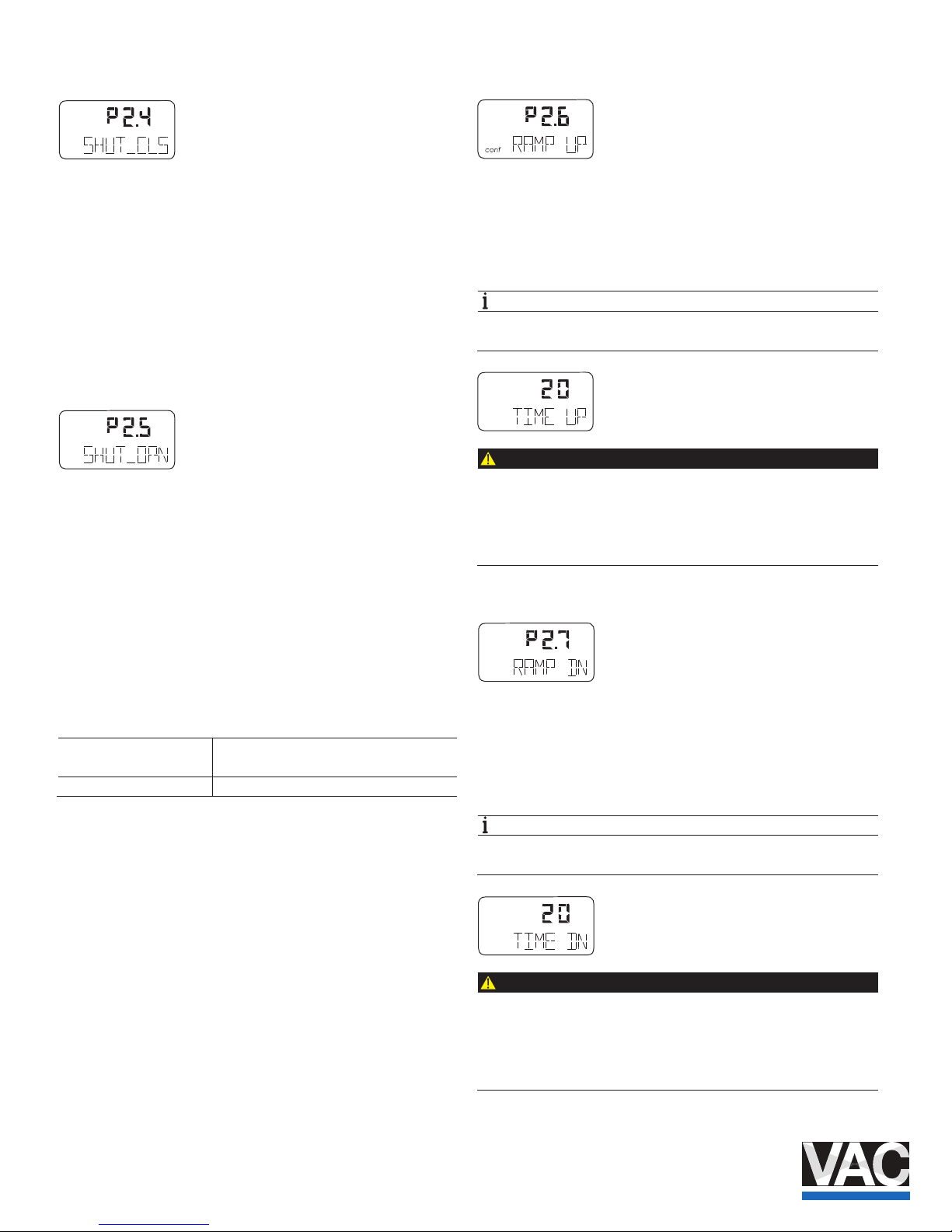
3.6.5 SHUT_CLS – Shut-o value 0%
The shut-o value SHUT_CLS is a percentage of the
operating range (with one deci mal place) from which the 0 %
position is approached. Once th e specied position limit value
is reached, the actuator move s into the 0% end position.
As a result, the valve is move d in control mode into the
mechanical 0% end position through full evacuation or
ventilation.
In the 0 % end position, it continues to be adjusted to the
position setpoint.
3.6.6 SHUT-OPN – Shut-o value 100%
The shut-o value SHUT_OPN is a percentage of the
operating range (with one de cimal place) from which the
100 % position is approached .
Once the specied position
limit value is reached, the actuator moves into the 100%
mechanical end position.
In the 100 % end position, it continues to be adjusted to the
position setpoint.
When entering a value, the valv e is moved in control mode into
the mechanical 100% end positi on through full evacuation or
ventilation.
Settings for Autoadjust:
Rotary actuators = 99 When the limit value is reached, the
actuator is fully ventilated.
Linear actuators = 100 Controlling continues in the 100% position.
3.6.7 RAMP UP – Setpoint ramp (up)
Here the stroke time for the actuator can be increased. A
setpoint change is not directly transferred to the positioner;
instead, the speed is reduced accordingly. The set value
should always be greater than the shortest stroke time
determined during auto adjust.
NOTE
To display the stroke time (stroke time up), press and hold
the ENTER button.
CAUTION
The setpoint ramp is deactivated in the case of any functions
which involve approaching th e safe position. This even
applies in the case of errors.
The actuator will therefore move without delay.
— Do not reach into the adjustment mechanism.
3.6.8 RAMP DN – Setpoint ramp (down)
Here the stroke time for the actuator can be increased. A
setpoint change is not directly transferred to the positioner;
instead, the speed is reduced accordingly. The set value
should always be greater than the shortest stroke time
determined during auto adjust.
NOTE
To display the stroke time (stroke time up), press and hold
the ENTER button.
CAUTION
The setpoint ramp is deactivated in the case of any functions
which involve approaching th e safe position. This even
applies in the case of errors.
The actuator will therefore move without delay.
— Do not reach into the adjustment mechanism.
conf
conf
conf
mA
%
C
conf
mA
%
C
co nf
mA
%
C
Page 17
TZIDC, TZIDC- 200 | COI/TZIDC/TZIDC-200-EN 17
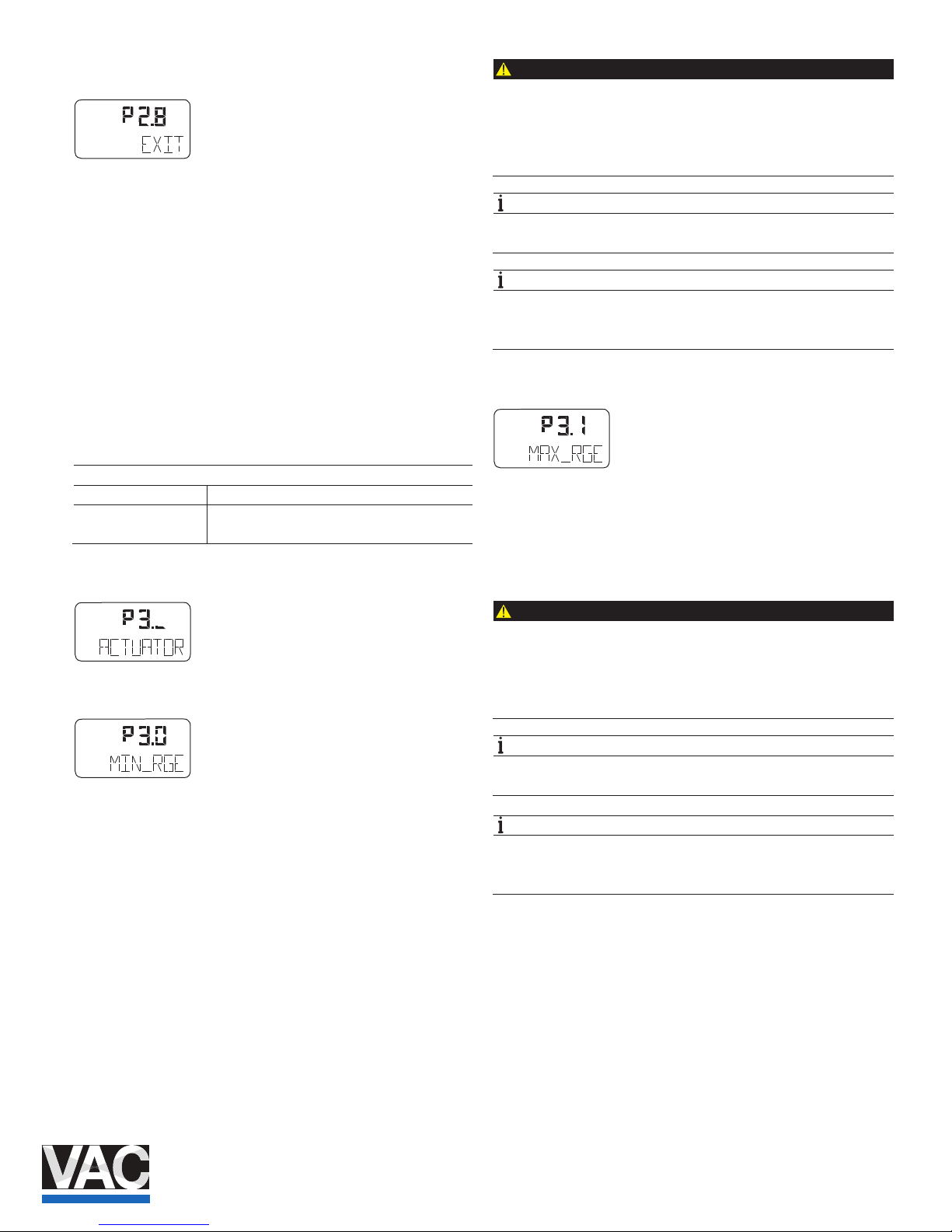
3.6.9 EXIT – Return to operating level
With this parameter you can leave the conguration level. The
positioner returns to the operating level. Here you can either
save data in the non-volatile me mory or discard all previously
made changes (also the changes in other parameter groups).
To leave the conguration level (with or without saving), press
and hold ENTER until the countdown from 3 to 0 is nished.
The active saving process is indicated by the message
NV_SAVE . After saving a plausibility check is executed.
If an error occurs during the check or while saving, the data
cannot be saved and an error messa
ge is displayed instead
(see Chapter "Error codes" on page 33).
Selection
NV_SAVE Saves settings in the non-volatile memory.
CANCEL Discards all changes made since the last
permanent save operation.
3.7 Parameter group 3: Operating range
3.7.1 MIN_RGE – Operating range min.
The working range can be congured to be smaller than the
maximum mechanical working range.
The setpoint range always refer s to the congured working
range. Use this parameter to specify the lower limit of the
operating range.
CAUTION
This function is only active in control mode.
In the event of a power supply fa ilure (electric or pneumatic),
and in manual mode, the mechanical end positions are
approached.
— Do not reach into the adjustment mechanism.
NOTE
The operating range must be greater than 10% of the sensor
range.
NOTE
The display of the positioner in operating modes 1.0 through
1.2 always refers to the co ngured working range and
indicates the position in %.
3.7.2 MAX_RGE – Operating range max.
The working range can be congured to be smaller than the
maximum mechanical working range.
The setpoint range always refer s to the congured working
range. Use this parameter to specify the upper limit of the
working range.
CAUTION
This function is only active in control mode.
In the event of a power supply fa ilure (electric or pneumatic),
and in manual mode, the mechanical end positions are
approached.
— Do not reach into the adjustment mechanism.
NOTE
The operating range must be greater than 10% of the sensor
range.
NOTE
The display of the positioner in operating modes 1.0 through
1.2 always refers to the co ngured working range and
indicates the position in %.
conf
mA
%
C
°
conf
conf
mA
%
C
°
conf
Page 18
18 COI/TZIDC/TZIDC-200- EN | TZI DC, TZIDC-200
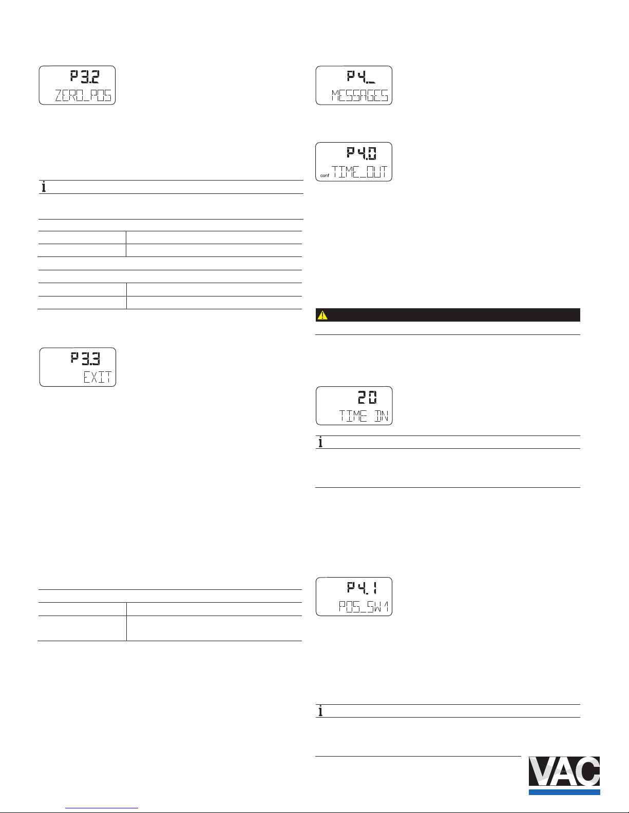
3.7.3 ZERO_POS – Zero position
With this parameter you can assign the zero position of the
display to the zero position of the valves and ttings. It also
allows you to select the direction of rotation of the sensor
shaft (looking at the open housing).
NOTE
Normally, the zero position is determined automatically and
saved during standard Autoadjust.
Linear actuators “counterclockwise ”
Rotary actuators “clockwise”
Selection
CLOCKW Limit stop reached turning clockwise
CTCLOCKW Limit stop reached turning counterclockwise
3.7.4 EXIT – Return to operating level
With this parameter you can leave the conguration level. The
positioner returns to the operating level. Here you can either
save data in the non-volatile me mory or discard all previously
made changes (also the changes in other parameter groups).
To leave the conguration level (with or without saving), press
and hold ENTER until the countdown from 3 to 0 is nished.
The active saving process is indicated by the message
NV_SAVE . After saving a plausibility check is executed.
If an error occurs during the check or while saving, the data
cannot be saved and an error message is displayed instead
(see Chapter "Error codes" on page 33).
Selection
NV_SAVE Saves settings in the non-volatile memory.
CANCEL Discards all changes made since the last
permanent save operation.
3.8 Parameter group 4: Messages
3.8.1 TIME_OUT – Dead band time limit
With this parameter you enter the monitoring time until
reaching the setpoint.
When the tolerance band is exceed ed, the monitoring time is
started. If the tolerance band within the predened time is
again not reached by the new po sition setpoint, an alarm is
triggered.
(Parameter TIME_OUT in parameter group 5 must be
activated.)
CAUTION
With active shutdown function there is no alarm message.
Once the setpoint has been reached, the alarm is
automatically reset.
NOTE
The stroke time to be monitored should be 1.5 to 2x greater
than the shortest stroke time selected during automatic
adjustment.
Press and hold the ENTER button to display the stroke time.
Press ENTER again to toggle between UP stroke time and
DOWN stroke time.
3.8.2 POS_SW1 – Switching point SW1
With this parameter you can dene the switching point SW1 as
a percentage of the operating range.
If the position is above or below SW1, the corresponding
signal output on the plug-in module is activated (see also
parameter group DIG_OUT on page 29).
NOTE
Changing the operating range also changes the positions of
the switching points with respect to the position of the valves
and ttings.
conf
mA
%
C
°
conf
mA
%
C
°
conf
co nf
mA
%
C
conf
mA
%
C
°
Page 19
TZIDC, TZIDC- 200 | COI/TZIDC/TZIDC-200-EN 19
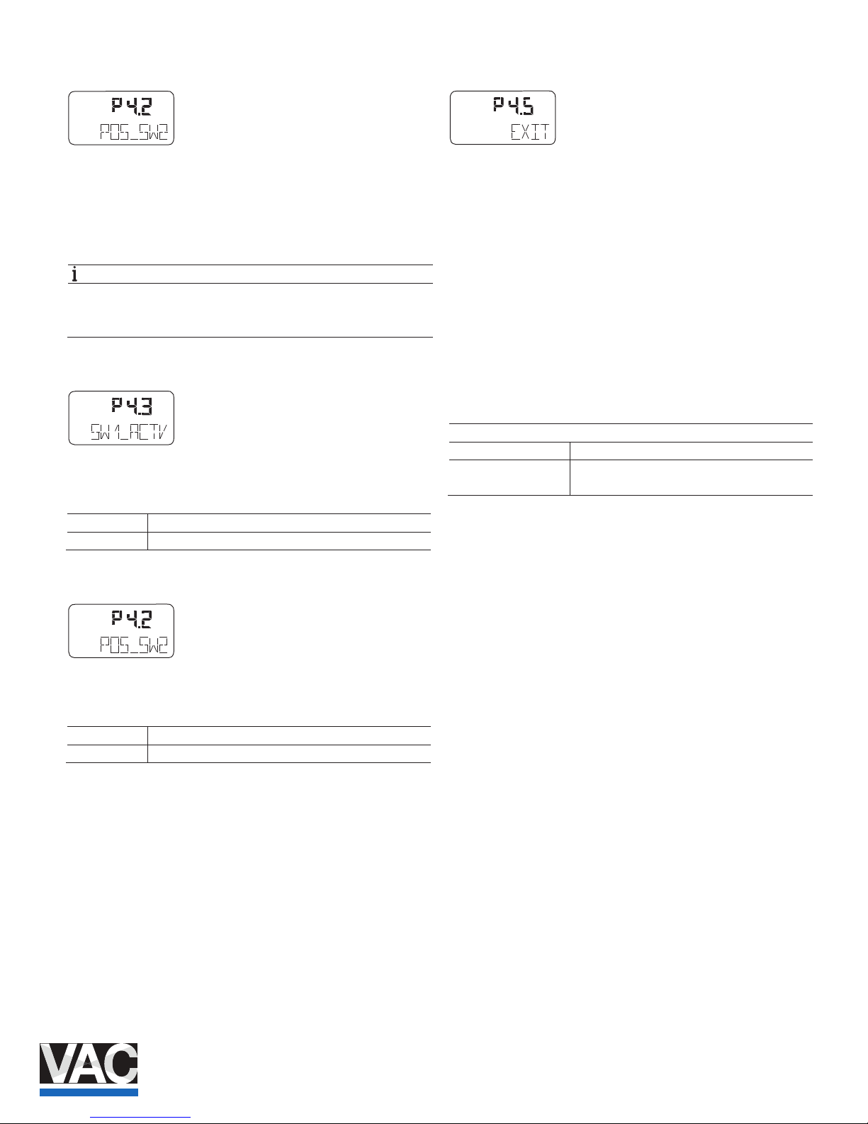
3.8.3 POS_SW2 – Switching point SW2
With this parameter you can dene the switching point SW2 as
a percentage of the operating range.
If the position is above or below SW2, the corresponding
signal output on the plug-in module is activated (see also
parameter group DIG_OUT on page 29).
NOTE
Changing the operating range also changes the positions of
the switching points with respect to the position of the valves
and ttings.
3.8.4 SW1_ACTV – Active direction SW1
With this parameter you dene whether a message is to be
triggered for exceeding or fallin g below switching point SW1.
EXCEED Message when exceeding switching point SW1.
FALL_BEL Message when falling below switching point SW1.
3.8.5 SW2_ACTV – Active direction SW2
With this parameter you dene whether a message is to be
triggered for exceeding or fallin g below switching point SW2.
EXCEED Message when exceeding switching point SW2.
FALL_BEL Message when falling below switching point SW2.
3.8.6 EXIT – Return to operating level
With this parameter you can leave the conguration level. The
positioner returns to the operating level. Here you can either
save data in the non-volatile me mory or discard all previously
made changes (also the changes in other parameter groups).
To leave the conguration level (with or without saving), press
and hold ENTER until the countdown from 3 to 0 is nished.
The active saving process is indicated by the message
NV_SAVE . After saving a plausibility check is executed.
If an error occurs during the check or while saving, the data
cannot be saved and an error message is displayed instead
(see Chapter "Error codes" on page 3
3).
Selection
NV_SAVE Saves settings in the non-volatile memory.
CANCEL Discards all changes made since the last
permanent save operation.
conf
mA
%
C
°
conf
mA
%
C
°
conf
mA
%
C
°
conf
mA
%
C
°
Page 20
20 COI/TZIDC/TZIDC-200- EN | TZI DC, TZIDC-200
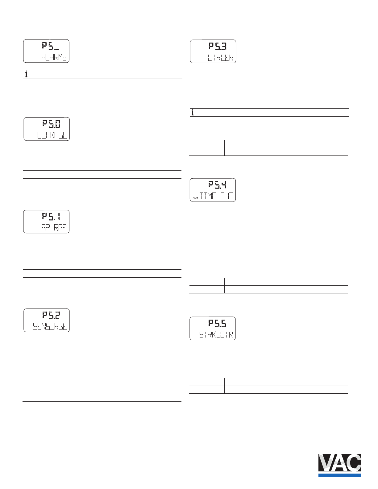
3.9 Parameter group 5: Alarms
NOTE
Active alarms are signaled at the digital output and using the
"Analog feedback" option.
3.9.1 LEAKAGE – Leakage at actuator
If the monitoring function detects leakage at the actuator, a
message is issued via alarm output on the mainboard.
ACTIVE Monitoring active.
INACTIVE Monitoring inactive.
3.9.2 SP_RGE – Setpoint monitoring
With this parameter, you can determine that a corresponding
alarm is signaled via the digita l output when falling below or
exceeding the setpoint range (< 3.8 mA or above 20.5 mA).
ACTIVE Setpoint monitoring active.
INACTIVE Setpoint monitoring inactive.
3.9.3 SENS_RGE – Operating range exceeded
With this parameter you can determine that an alarm is
signaled via the digital output when the congured operating
range is exceeded by 4%. (Pos ition < -4 % or > 104 %).
This may indicate improperly ad justed mounting or mechanical
wear in a limit stop.
ACTIVE Alarm active.
INACTIVE Alarm not active.
3.9.4 CTRLER – Controller inactive
You can use this parameter to speci fy signaling of an alarm via
a digital output if the positioner is not active, i.e., if the control
mode is interrupted by another operating mode or by
conguration.
NOTE
For details of which statuses lead to a message, see see
Chapter "Alarm codes" on page 35.
ACTIVE Alarm active.
INACTIVE Alarm not active.
3.9.5 TIME_OUT – Dead band time limit
Use this parameter to activate the "Dead band time limit"
function.
The alarm is issued via digital ou tput when the setpoint within
the specied monitoring time is not reached in control mode.
(The monitoring time is entered with parameter group 4,
„TIME_OUT“ .) The function is only active in control modes
ACTUATOR and AUTO_ADJ .
ACTIVE Dead band time limit is activated.
INACTIVE Alarm not active.
3.9.6 STRK_CTR – Movement counter
With this parameter you can determine that an alarm is
signaled when the movement counter exceeds the specied
limit value. The limit value is edited remotely via PC.
ACTIVE Alarm for exceeding travel counter limit value
INACTIVE No Alarm
conf
mA
%
C
°
conf
mA
%
C
°
conf
mA
%
C
°
conf
mA
%
C
°
conf
mA
%
C
°
conf
mA
%
C
°
Page 21
TZIDC, TZIDC- 200 | COI/TZIDC/TZIDC-200-EN 21
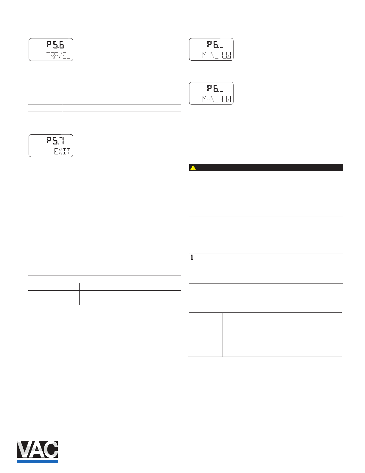
3.9.7 TRAVEL – Travel counter
With this parameter you can determine that an alarm is
signaled when the travel counter exceeds the specied limit
value. The limit value is edited remotely via PC.
ACTIVE Alarm for exceeding movement counter limit value
INACTIVE No Alarm
3.9.8 EXIT – Return to operating level
With this parameter you can leave the conguration level. The
positioner returns to the operating level. Here you can either
save data in the non-volatile me mory or discard all previously
made changes (also the changes in other parameter groups).
To leave the conguration level (with or without saving), press
and hold ENTER until the countdown from 3 to 0 is nished.
The active saving process is indicated by the message
NV_SAVE . After saving a plausibility check is executed.
If an error occurs during the check or while saving, the data
cannot be saved and an error message is displayed instead
(see Chapter "Error codes" on page 33).
Selection
NV_SAVE Saves settings in the non-volatile memory.
CANCEL Discards all changes made since the last
permanent save operation.
3.10 Parameter group 6: Manual adjustment
3.10.1 MIN_VR – Operating range min.
Normally, the operating range is determined automatically
during Autoadjust. A partial run of automatic adjustment that is
limited to the controller parameters ( CTRL_PAR , see
parameter DANG_DN on page 23) or valves and ttings
without end stops, however, requires manual adjustment of
the operating range.
CAUTION
Risk of injury!
After manual adjustment of the end positions, it is essential
to limit the operating range to > 0.1 and < 99.9 under
MIN_RGE and MAX_RGE . Otherwise, the valves and ttings
may be driven at full speed to an end position.
— Do not reach into the adjustment mechanism.
The range between high and low limit value must be at least
10% of the full range. Otherwise, the message VR< 10 % is
displayed.
NOTE
Use as large are range as possible. This parameter is not
active when the safe position is active. The display then
shows the message FAIL_POS .
Use MIN_VR to determine the lower limit of the operating
range.
or Press in order to travel to the desired position.
ENTER Press and hold until the countdown has completed
(MIN_SET). The position is saved as the minimum limit
value.
ENTER Press briey. The set limit value is displayed for 2
seconds (MIN_SAVE). .
conf
mA
%
C
°
conf
mA
%
C
°
conf
conf
Page 22
22 COI/TZIDC/TZIDC-200- EN | TZI DC, TZIDC-200
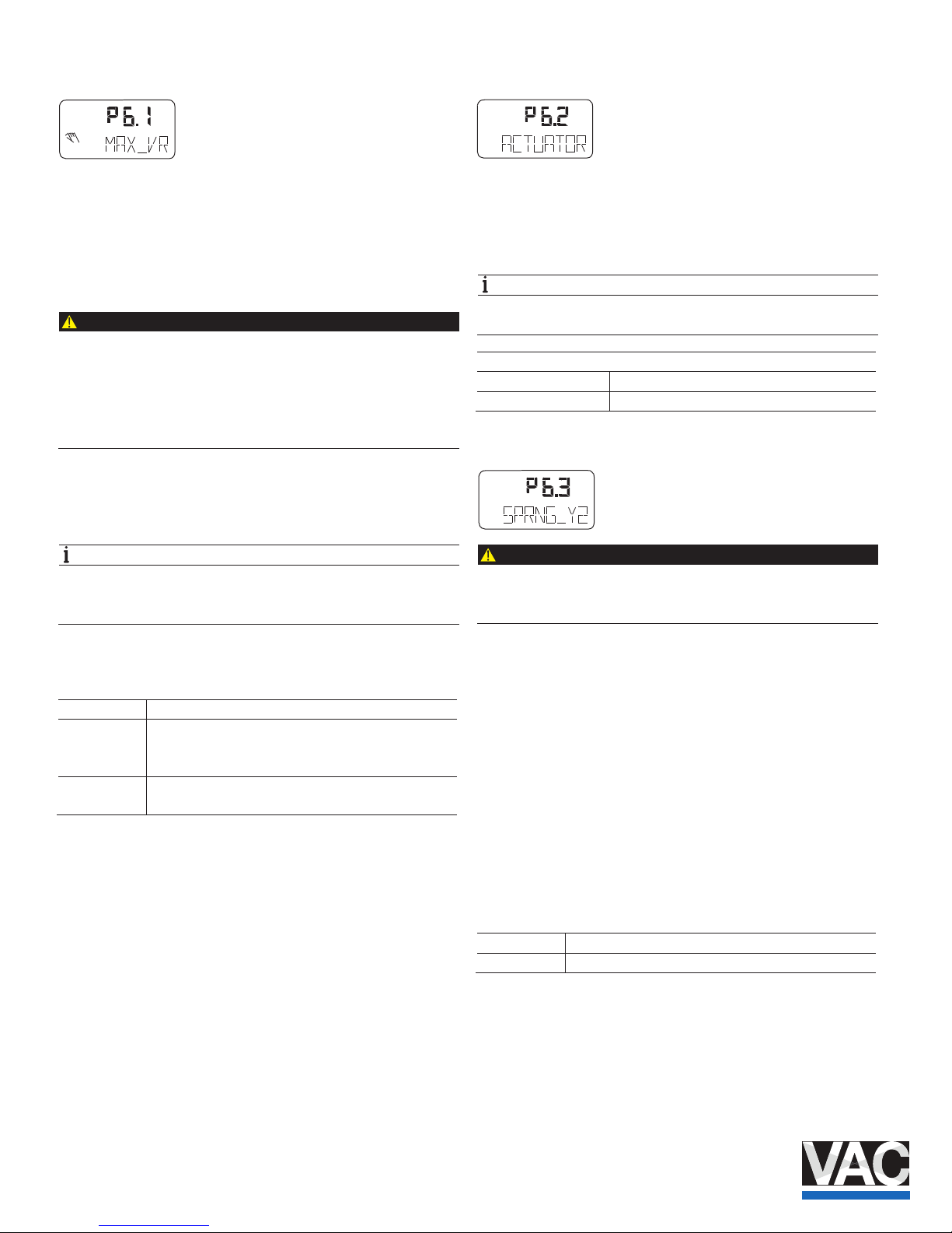
3.10.2 MAX_VR – Operating range max.
Normally, the operating range is determined automatically
during Autoadjust. A partial run of automatic adjustment that is
limited to the controller data (STANDARD , see parameter
ADJ_MODE on page 12) or valves and ttings without end
stops, however, requires manua l adjustment of the operating
range.
CAUTION
Risk of injury!
After manual adjustment of the end positions, it is essential
to limit the operating range to > 0.1 and < 99.9 under
MIN_RGE and MAX_RGE . Otherwise, the valves and ttings
may be driven at full speed to an end position.
— Do not reach into the adjustment mechanism.
The range between high and low limit value must be at least
10% of the full range. Otherwise, the message VR< 10 % is
displayed.
NOTE
Use as large are range as possible. This parameter is not
active when the safe position is active. The display then
shows the message FAIL_POS .
Use MAX_VR to determine the upper limit of the operating
range.
or Press in order to travel to the desired position.
ENTER Press and hold until the countdown has completed
(MIN_SET). The position is saved as the minimum limit
value.
ENTER Press briey. The set limit value is displayed for 2
seconds (MIN_SAVE). .
3.10.3 ACTUATOR – Actuator type
With this parameter you can congure the positioner for
operation on a linear actuator (sensor range ±30°) or on a
part-turn actuator (sensor ra nge ±45°). No mechanical
modications to the positioner are required.
NOTE
After changing the actuator type , it is recommended that you
run Auto Adjust to pr event linearity errors.
Selection
LINEAR Linear actuator
ROTARY Part-turn actuator
3.10.4 SPRNG_Y2 – Spring action (Y2)
CAUTION
Risk of injury!
Incorrect entries may result in the actuator traveling
to a mechanical stop at full speed.
Use this parameter to specify the end position to which the
reset spring of the pneumatic actuator drives the valves and
ttings in the event that the power supply fails.
The corresponding end stop is determined during Autoadjust.
If, however, only the controller data are determined
(STANDARD , see parameter ADJ_MODE ), the spring action
must be entered manually.
Select the direction of rotation of the sensor shaft (looking at
the open housing) for when the safe position is approached as
a result of the spring force (actuator exhausts via OUT1 ). For
double-acting actuators, the spri ng action has the same eect
as ventilating the pneumatic output OUT2 .
CLOCKW Stop reached turning clockwise
CTCLOCKW Stop reached turning counterclockwise
conf
mA
%
C
°
conf
conf
mA
%
C
°
Page 23
TZIDC, TZIDC- 200 | COI/TZIDC/TZIDC-200-EN 23
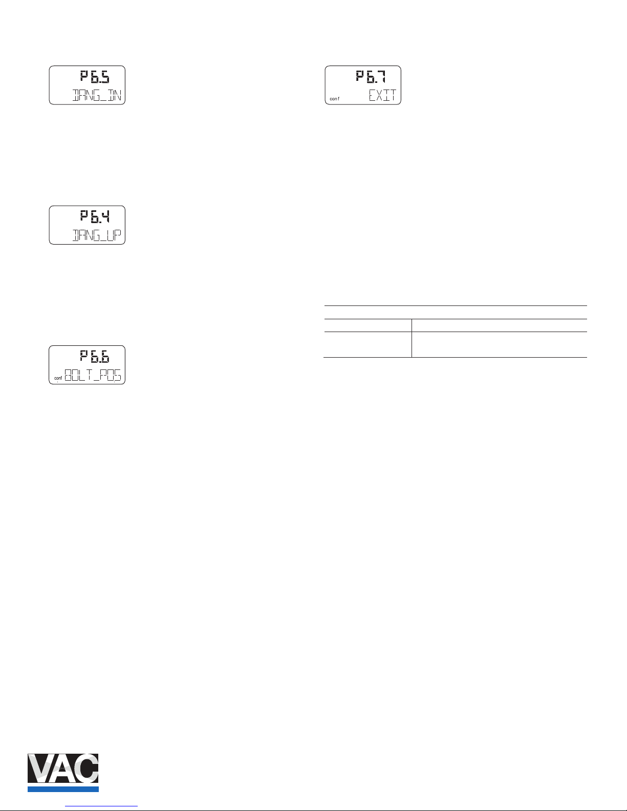
3.10.5 DANG_DN – Dead Angle Close
Use this parameter to cut o the unusable range of the valve
ow characteristic curve from th e point of view of control.
The Dead Angle Close is a percentage of the operating range
to which the valve is moved if the input signal is 4.16 mA.
3.10.6 DANG_UP – Dead Angle Open
Use this parameter to cut o the unusable range of the valve
ow characteristic curve from th e point of view of control.
The Dead Angle Open is a percentage of the operating range
to which the valve is moved if the input signal
is 19.84 mA.
3.10.7 BOLT_POS – Actuator position
The installation type of the actuator bolt for the potentiometer
has a decisive inuence on the linearization of the
potentiometer signal.
Using the function BOLT_POS, this installation type is taken
into account in the algorithm. The following options can be
selected:
— STEM (actuator bolt on the valve spindle)
— LEVER (actuator bolt on the potentiometer lever)
For detailed information about the position of the actuator
bolt, see the operat ing instructions.
3.10.8 EXIT – Return to operating level
With this parameter you can leave the conguration level. The
positioner returns to the operating level. Here you c
an either
save data in the non-volatile me mory or discard all previously
made changes (also the changes in other parameter groups).
To leave the conguration level (with or without saving), press
and hold ENTER until the countdown from 3 to 0 is nished.
The active saving process is indicated by the message
NV_SAVE . After saving a plausibility check is executed.
If an error occurs during the check or while saving, the data
cannot be saved and an error message is displayed instead
(see Chapter "Error codes" on page 33).
Selection
NV_SAVE Saves settings in the non-volatile memory.
CANCEL Discards all changes made since the last
permanent save operation.
con f
mA
%
C
°
con f
mA
%
C
°
Page 24
24 COI/TZIDC/TZIDC-200- EN | TZI DC, TZIDC-200
3.11 Parameter group 7: Control parameters
3.11.1 KP UP – KP value (up)
NOTE
In the case of most actuators, all control parameters can be
optimized by using Auto Adjust. Changes should only be
made when auto adjust cannot be executed or control
stability cannot be achieved.
The KP value is the gain of th e controller. Th e control speed
and stability are inuenced by th e KP value. With higher KP
values, the control speed increases.
NOTE
The control precision is n ot aected by the KP value.
To compensate for existing di ssymmetries in the controlled
system, the KP value should be set separately for both
positioning directions (up / down).
For most actuators, a satisfactory control response is
achieved with a KP value in the 2.0 ... 10.0 range.
Use the parameter KP UP to adjust the KP value for the
upward positioning direction (towards 100 %).
3.11.2 KP DN – KP value (down)
NOTE
In the case of most actuators, all control parameters can be
optimized by using Auto Adjust. Changes should only be
made when auto adjust cannot be executed or control
stability cannot be achieved.
The KP value is the gain of th e controller. Th e control speed
and stability are inuenced by th e KP value. With higher KP
values, the control speed increases.
NOTE
The control precision is n ot aected by the KP value.
To compensate for existing as ymmetries in the controlled
system, the KP value should be set separately for both
positioning directions (up / down).
For most actuators, satisfactor y control behavior is achieved
with a KP value between 2.0 ... 10.0.
Use the KP DN parameter to adjust the KP value for the
downward positioning direction (towards 0 %).
3.11.3 TV UP – TV value (up)
NOTE
In the case of most actuators, all control parameters can be
optimized by using Auto Adjust. Changes should only be
made when auto adjust cannot be executed or control
stability cannot be achieved.
The TV value is the derivative time of the controller.
The control speed and stability are aected by the TV value in
such a way that it counteracts the KP value dynamically. The
control speed decreases as the TV value increases.
To compensate for existing di ssymmetries in the controlled
system, the TV value should be congured separately for both
positioning directions (up / down).
Use the TV UP parameter to adjust the TV value for the
upward positioning direction (towards 100 %).
conf
conf
mA
%
C
°
conf
mA
%
C
°
conf
mA
%
C
°
Page 25
TZIDC, TZIDC- 200 | COI/TZIDC/TZIDC-200-EN 25
3.11.4 TV DN – TV value (down)
NOTE
In the case of most actuators, all control parameters can be
optimized by using Auto Adjust. Changes should only be
made when auto adjust cannot be executed or control
stability cannot be achieved.
The TV value is the derivative time of the controller.
Control speed and stability are aected by the TV value in
terms of how this dynamically counteracts the KP value. The
control speed decreases as the TV value increases.
To compensate for existing as ymmetries in the controlled
system, the TV value should be congured separately for both
positioning directions (up / down).
Use the TV DN parameter to adjust the TV value for the
downward positioning direction (towards 0 %).
3.11.5 Y-OFS UP – Y oset (up)
NOTE
In the case of most actuators, all control parameters can be
optimized by using Auto Adjust. Changes should only be
made when auto adjust cannot be executed or control
stability cannot be achieved.
The "oset for the setpoint signal" linearizes the behavior of
the I/P module used and enable s rapid compensation even in
the case of small control deviatio ns. The value is limited at the
lower end by a minimum value (neutral zone).
The oset signicantly aects the control speed for control
deviations of less than 5 %.
In manual modes MANUAL and MAN_SENS , the oset values
are issued to the I/P module fo r ne adjustment. With larger,
slower actuators, Autoadjust may determine oset values
higher than 80 %. In these ca ses there will be no noticeable
dierence between ne and coarse adjustment while in manual
mode.
To compensate for existing as ymmetries in the controlled
system, the oset should be co ngured separately for both
positioning directions (up / down).
For most actuators, satisfactor y control behavior is achieved
with oset values between 40 ... 80 %. If, in the event of
setpoint changes, the contro l behavior demonstrates an
overshoot of less than 2 %, both oset values should be
decreased.
Both oset values should be increased when the actuator
stops outside the tolerance band.
Use the parameter Y-OFS UP to adjust the Y oset for the
upward positioning direction (towards 100 %).
3.11.6 Y-OFS DN – Oset (down)
NOTE
In the case of most actuators, all control parameters can be
optimized by using Auto Adjust. Changes should only be
made when auto adjust cannot be executed or control
stability cannot be achieved.
The "oset for the setpoint signal" linearizes the behavior of
the I/P module used and enable s rapid compensation even in
the case of small control deviatio ns. The value is limited at the
lower end by a minimum value (neutral zone).
The oset signicantly aects the control speed for control
deviations of less than 5 %.
In manual modes MANUAL and MAN_SENS , the oset values
are issued to the I/P module fo r ne adjustment. For larger,
slower actuators Autoadjust may determine values higher than
80 %. In these cases there w ill be no noticeable dierence
between ne and coarse adjustment while in manual mode.
To compensate for existing as ymmetries in the controlled
system, the oset should be co ngured separately for both
pos
itioning directions (up / down).
For most actuators, a satisfactory control response is
achieved with oset values in the 40 ... 80 % range. If, in the
event of setpoint changes, the control behavior demonstrates
an overshoot of less than 2 %, both oset values should be
decreased.
Both oset values should be increased when the actuator
stops outside the tolerance band.
Use the parameter Y-OFS DN to adjust the Y oset for the
downward positioning direction (towards 0 %).
conf
mA
%
C
°
conf
mA
%
C
°
conf
mA
%
C
°
Page 26
26 COI/TZIDC/TZIDC-200- EN | TZI DC, TZIDC-200
3.11.7 TOL_BAND – Tolerance band
The "tolerance band" TOL_BAND denes a ± range around
the position setpoint. When the position of the valves and
ttings reaches this range, the parameter set of the positioner
is toggled to a dierent algorithm that is used to continue with
a slow controlling actio n until the dead band DEADBAND is
reached.
The system is only considered balanced once the sensitivity
range is reached (see parameter ADJ_MODE on page 12.)
Input value in steps of 0.1 %
3.11.8 DEADBAND – Dead band
The "dead band" DEADBAND denes a ± range around the
position setpoint. Once the valv es and ttings reach this
range, the positioner maintains this position.
NOTE
The dead band must always be 0.2% less than the tolerance
band.
Input value in steps of 0.01 %
3.11.9 DB_APPR – Dead band approach
The DB_APPR parameter species the speed at which the
dead band is approached.
In rare cases, overshooting can occur when the valve position
is being compensated. This can be prevented by reducing the
speed of the dead -band approach.
TEST – Test
The test is used to activate the controller, and you can check
the eects of the changes to this parameter group, e.g., by
introducing setpoint changes or setpoint ramps using a
current source.
Normally, INACTIVE is shown in the display. To start the test,
press and hold ENTER until the countdown from 3 to 0 is
nished. The test is activated . The display shows the control
loop symbol and a ashing message.
The test is automatically sto pped after
two minutes and can
also be stopped by pressing any button.
NOTE
It is not possible to activate the test when the safe position is
active (see parameter FAIL_POS on page 31). Instead, the
message FAIL_POS is displayed.
3.11.10 DB_CALC – Dead-band determination
In standard automatic adjustme nt, the algorithm determines
the dead band as well as th e end positions and control
parameters. In some applications, you may need to perform a
new automatic adjustment after in stallation in the system, but
to leave the dead band at a preset value.
DB_CALC oers the following setting options:
— ON (automatic adjustment with dead band determination)
— OFF (automatic adjustment without dead band
determination)
conf
mA
%
C
°
conf
mA
%
C
°
conf
mA
%
C
°
conf
mA
%
C
°
Page 27
TZIDC, TZIDC- 200 | COI/TZIDC/TZIDC-200-EN 27
3.11.11 LEAK_SEN – Leakage sensitivity
Determination of a possible leakage between the output
positioner and the pneumatic actuator. If the valve position
moves out of the dead zone (dead band) in the same direction
seven times in succession within a dened time range, there is
a high probability of a leakage in the connecting lines between
the positioner and the pneumatic actuator. LEAK_SEN
enables you to dene the time range within which the valve
may leave the dead band a maximum of seven times in
succession before an alarm is generated. You can choose a
time range of between 1 and 7200 seconds.
3.11.12 EXIT – Return to operating level
With this parameter you can leave the conguration level. The
positioner returns to t
he operating level. Here you can either
save data in the non-volatile me mory or discard all previously
made changes (also the changes in other parameter groups).
To leave the conguration level (with or without saving), press
and hold ENTER until the countdown from 3 to 0 is nished.
The active saving process is indicated by the message
NV_SAVE . After saving a plausibility check is executed.
If an error occurs during the check or while saving, the data
cannot be saved and an error message is displayed instead
(see Chapter "Error codes" on page 33).
Selection
NV_SAVE Saves settings in the non-volatile memory.
CANCEL Discards all changes made since the last
permanent save operation.
3.12 Parameter group 8: Analog output
(on the plug-in module for analog feedback)
3.12.1 MIN_RGE – Current range min.
Use this parameter to specify the lower current range limit for
the analog feedback. The current range corresponds to the
congured stroke range.
NOTE
The current range limits can be freely congured between
4 … 18.5 mA. However, the current range must not be
smaller than 10 % (1.6 mA).
3.12.2 MAX_RGE – Current range max.
Use this parameter to specify the upper current range limit for
the analog feedback.
NOTE
The current range limits can be freely congured between
4 … 20 mA. However, the current range must not be smaller
than 10 % (1.6 mA).
3.12.3 ACTION – Characteristic curve action
Use this parameter to specify th e characteristic curve for the
analog feedback.
Increasing Position 0 ... 100 % = Signal 4 ... 20 mA
Decreasing Position 0 ... 100 % = Signal 20 ... 4 mA
conf
mA
C
conf
conf
conf
mA
%
C
°
conf
mA
%
C
°
Page 28
28 COI/TZIDC/TZIDC-200- EN | TZI DC, TZIDC-200
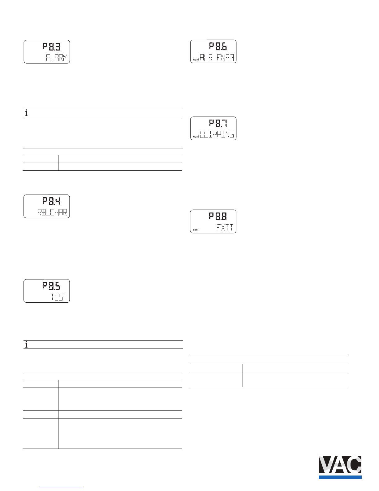
3.12.4 ALARM – Alarm
When an alarm / message is generated in the positioner, it is
signaled via the digital and an alog outputs. You can use the
ALARM parameter to select a higher or lower alarm current for
analog feedback.
NOTE
Without electrical power or during initialization the output
signal is > 20.5 mA. A special version (hardware change) is
also available, with which a value of < 3.8 mA is also
possible.
HIGH_CUR Alarm current I > 20.5 mA
LOW_CUR Alarm current I < 3.8 mA
3.12.5 RB_CHAR – Count back characteristic curve
You can use this parameter to determine whether the position
indicator and the analog po sition feedback follow the
characteristic curve set in parameter CHARACT Characteristic curve.
3.12.6 TEST – Test
Test is for simulation of the analog output. The test allows you
to simulate eects during commi ssioning without aecting the
normal process.
NOTE
The test is automatically stopped after two minutes.
While the test is running, th e corresponding message (see
below) ashes in the display.
NONE No function
FAILED Simulation of position feedback failure (CPU).
I > 20.5 mA (standard) or I < 3.8 mA (special version,
changed hardware)
ALRM_CUR Simulation of an alarm curr ent < 3.8 mA or I > 20.5 mA
CURRENT Output of the current setpoint as current value via
analog output. All congurations and settings of the
analog input and / or output must be taken into
consideration.
3.12.7 ALR_ENAB – Alarm via analog output
Enables the alarm signal to be switched on / o using the
optional analog output module.
Selection option: ON / OFF .
3.12.8 CLIPPING – Extending the signal output range
Enables extension of the permissible signal output range to
3.8 … 20.5 mA.
Selection option:
— 4.0 … 20.0 mA
— 3.8 … 20.5 mA
3.12.9 EXIT – Return to operating level
With this parameter you can leave the conguration level. The
positioner returns to the operating level. Here you can either
save data in the non-volatile me mory or discard all previously
made changes (also the changes in other parameter grou
ps).
To leave the conguration level (with or without saving), press
and hold ENTER until the countdown from 3 to 0 is nished.
The active saving process is indicated by the message
NV_SAVE . After saving a plausibility check is executed.
If an error occurs during the check or while saving, the data
cannot be saved and an error message is displayed instead
(see Chapter "Error codes" on page 33).
Selection
NV_SAVE Saves settings in the non-volatile memory.
CANCEL Discards all changes made since the last
permanent save operation.
conf
conf
mA
%
C
°
conf
mA
%
C
°
Page 29
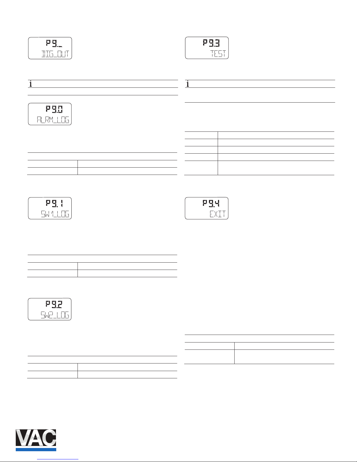
TZIDC, TZIDC- 200 | COI/TZIDC/TZIDC-200-EN 29
3.13 Parameter group 9: digital output
3.13.1 ALRM_LOG – Alarm output logic
NOTE
SW1 and SW2 are on the plug-i n module for digital feedback
With this parameter you can determine the logic level of the
alarm output.
Selection
ACTIV_HI active = output current I > 2 mA
ACTIV_LO active = output current I < 1 mA
3.13.2 SW1_LOG – Logic
You can use this parameter to dene the active state for
switch output SW1 (on the plug-in module for digital
feedback).
Selection
ACTIV_HI active = output current I > 2 mA
ACTIV_LO active = output current I < 1 mA
3.13.3 SW2_LOG – Logic
You can use this parameter to dene the active state for
switch output SW2 (on the plug-in module for digital
feedback).
Selection
ACTIV_HI active = output current I > 2 mA
ACTIV_LO active = output current I < 1 mA
TEST – Test
Test is for simulation for the digital output.
NOTE
The test is automatically sto pped after two minutes and can
be aborted by pressing any button.
While the test is running, th e corresponding message (see
below) ashes in the display.
NONE No function
ALRM_ON Alarm is simulated (DO active)
SW1_ON Reaching switching point 1 is simulated (SW1 active)
SW2_ON Reaching switching point 2 is simulated (SW2 active)
ALL_ON Alarm and switching points are simulated (all DOs
active)
3.13.4 EXIT – Return to operating level
With this parameter you can leave the conguration level. The
positioner returns to the operating level. Here you can either
save data in the non-volatile me mory or discard all previously
made changes (also the changes in other parameter groups).
To leave the conguration level (with or without saving), press
and hold ENTER until the countdown from 3 to 0 is nished.
The active saving process is indicated by the message
NV_SAVE . After saving a plausibility check is executed.
If an error occurs during the check or while saving, the data
cannot be saved and an error message is displayed instead
(see Chapter "Error codes" on page
33).
Selection
NV_SAVE Saves settings in the non-volatile memory.
CANCEL Discards all changes made since the last
permanent save operation.
conf
mA
%
C
°
conf
mA
%
C
°
conf
mA
%
C
°
conf
mA
%
C
°
conf
mA
%
C
°
conf
mA
%
C
°
Page 30
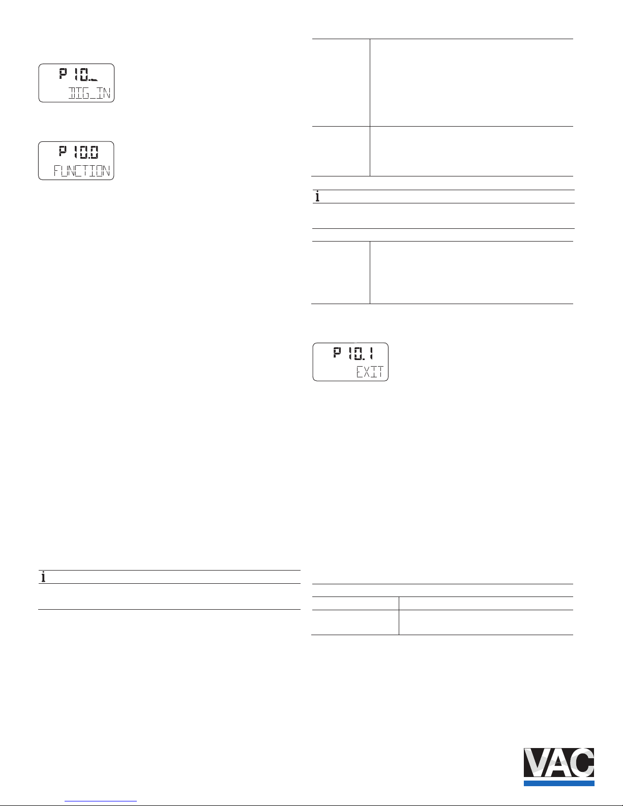
30 COI/TZIDC/TZIDC-200- EN | TZI DC, TZIDC-200
3.14 Parameter group 10: digital input
3.14.1 FUNCTION – Digital input function selection
For the digital input, one of the following protective functions
can be selected via local operation.
— No function (default)
— Move to 0 % position
— Move to 100 % position
— Hold previous position
— Disable local conguration.
— Disable local cong uration and operation
— Disable all access (local or via PC)
The selected function is activat ed when the 24 V signal is no
longer connected to the digital output (< 10 V DC).
The safety functions POS_0 % , POS_100 % and POS_HOLD
are executed on the operating le vel in both control ope
rating
modes P1.0 or P1.1 . BIN_CTRL is shown in the display.
If a corresponding function is active, a corresponding value is
dened internally for the positioner. The actuator is then driven
into the end position or position specied under consideration
of the set point ramp, congured operating range, selected
behavior etc.
After selecting an operation lock CNF_LOCK , OP_LOCK or
ALL_LOCK , the key icon is displayed, indicating that the
operation lock will be activ ated at the next save.
After saving and without 24V at the digital input, the key is
permanently displayed.
NOTE
The operation lock CNF_LOCK , OP_LOCK or ALL_LOCK is
displayed only if the voltage is connected to the digital input.
CNF_LOCK Local access to the conguration level is inhibited.
However, local operation on the operating level is
possible. The positioner can be congured externally
(via LCI / modem and PC).
When the operator tries to activate the conguration
level, the text CNF_LOCK is displayed for approx. 5
seconds.
OP_LOCK Local operation and conguration is completely
inhibited. With every attempt to perform local operating
actions, the message OP_LOCK is shown for approx. 5
seconds.
NOTE
The positioner can be congured externally (via LCI / modem
and PC).
ALL_LOCK Local operation (operating level and conguration level)
and external conguration via LCI / modem and PC are
inhibited. With every attempt to perform local operating
actions, the message ALL_LOCK is shown for approx.
5 seconds.
3.14.2 EXIT – Return to operating level
With this parameter you can leave the conguration level. The
positioner returns to the operating level. Here you can either
save data in the non-volatile me mory or discard all previously
made changes (also the changes in other parameter groups).
To leave the conguration level (with or without saving), press
and hold ENTER until the countdown from 3 to 0 is nished.
The active saving process is indicated by the message
NV_SAVE . After saving a plausibility check is executed.
If an error occurs during the check or while saving, the data
cannot be saved and an error message is displayed instead
(see Chapter "Error codes" on page
33).
Selection
NV_SAVE Saves settings in the non-volatile memory.
CANCEL Discards all changes made since the last
permanent save operation.
conf
mA
%
C
°
conf
mA
%
C
°
conf
mA
%
C
°
Page 31
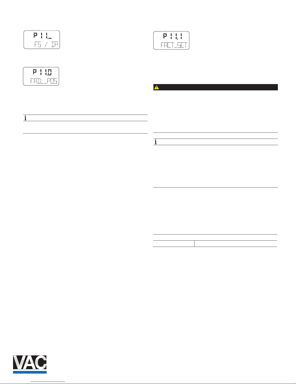
TZIDC, TZIDC- 200 | COI/TZIDC/TZIDC-200-EN 31
3.15 Parameter group 11: Safe position
3.15.1 FAIL_POS – Safe position
This parameter must be used to activate the safe position prior
to loading the factory settings (parameter FACT_SET ) or
changing the I/P module type (parameter I IP-TYP ).
NOTE
After setting parameters FACT_SET and IP-TYP as required,
the safe position must be deactivated again manually.
The safe position that is activa ted (i.e., whether the actuator is
ventilated or blocked) depends on the I/P module installed.
Activating / deactivati ng the safe position:
Press and hold ENTER until the displayed countdown from 3
to 0 is nished. Then release ENTER .
The safe position is activated or deactivated, respectively.
3.15.2 FACT_SET – Factory setting
You can use this parameter to reset the positioner to the
factory setting. This is necessary, e.g., if an already congured
positioner has to be installe d on a dierent actuator and
subsequently recongured.
CAUTION
Risk of injury!
For safety reasons, after loading the factory settings you
must check whether the I/P module type that is set matches
the actual I/P module type present in the device.
Otherwise dangerous situations may occur when operating in
control mode. It may happen that the actuator is driven at full
speed to the end position.
NOTE
You can only load the factory sett ings when the actuator is in
the safe position (parameter FAIL_POS ). Otherwise, this
action is inhibited and the message NO_F_POS is indicated
in the display.
If you save the settings in the non-volatile memory after
loading the factory settings, operating mode 1.3 is
automatically activated on the operating level.
Load factory settings:
Press and hold ENTER until the displayed countdown from 3
to 0 is nished.
The positioner is reset to th e factory settings. The message
COMPLETE is displayed.
Press ENTER to acknowledge the message.
Selection
FS_LOAD Loads the factory settings
con f
mA
%
C
°
conf
mA
%
C
°
conf
mA
%
C
°
Page 32
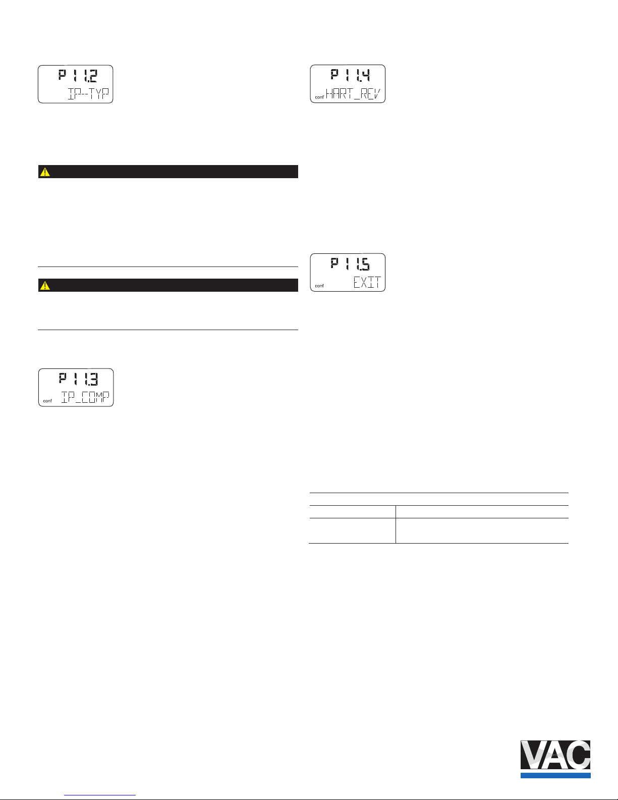
32 COI/TZIDC/TZIDC-200- EN | TZI DC, TZIDC-200
3.15.3 IP-TYP – Type of the I/P module
Use this parameter to adapt the positioner software to the
installed I/P module. This is requ ired when installing a dierent
I/P module type.
CAUTION
Risk of injury!
For safety reasons, after loading the factory settings you
must check whether the I/P module type that is set matches
the actual I/P module type pres ent in the device. Otherwise
dangerous situations may occu r when operating in control
mode. It may happen that the act uator is driven at full speed
to the end position.
CAUTION
For safety reasons, after rest oring the positioner to the
factory settings you must check whether this parameter has
been correctly set.
3.15.4 IP_COMP – IP Compensation
This function is reserved for use by ABB Service only.
3.15.5 HART_REV – HART version
As of rmware version 5, the positioner oers communication
via both standard HART 5 and HART 7. To select, use the
arrow keys or .
Squawk command:
A standardized HART-7 comma nd causes the bottom menu
line in the HMI of the addressed device to ash. This visual aid
makes it easier to identify the addressed device in the system.
3.15.6 EXIT – Return to operating level
With this parameter you can leave the conguration level. The
positioner returns to the operating level. Here you can either
save data in the non-volatile me mory or discard all previously
made changes (also the changes
in other parameter groups).
To leave the conguration level (with or without saving), press
and hold ENTER until the countdown from 3 to 0 is nished.
The active saving process is indicated by the message
NV_SAVE . After saving a plausibility check is executed.
If an error occurs during the check or while saving, the data
cannot be saved and an error message is displayed instead
(see Chapter "Error codes" on page 33).
Selection
NV_SAVE Saves settings in the non-volatile memory.
CANCEL Discards all changes made since the last
permanent save operation.
Change from two to one column
conf
Page 33
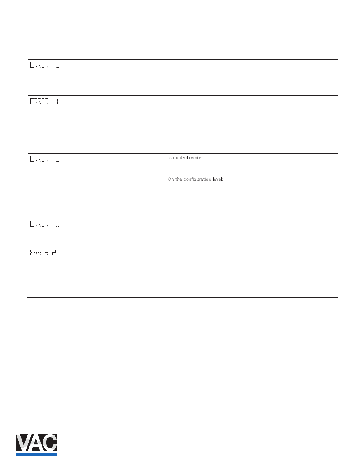
TZIDC, TZIDC- 200 | COI/TZIDC/TZIDC-200-EN 33
4 Diagnosis / error messages
4.1 Error codes
Error code Possible cause Impact Troubleshooting the Instrument
The supply voltage was interrupted for
at least 20 ms.
(This error is displayed after resetting the
device to indicate the reason for the
reset.)
.gniriw eht dna ecruos rewop eht kcehC -
The supply voltage has fallen below the
minimum voltage.
The actuator is moved to the safe
position. After approx. 5 seconds, the
positioner is automatically reset and
starts up again with the message
ERROR 10 . If a local communication
interface (LCI) is plugged in, the device
will enter the operating mode LCI
supply.
Check the power source and the wiring.
The position is outside the measuring
range. Possible reason is a malfunction
in the position sensor.
In control mo de:
The actuator is moved to the safe
position.
O
n the configura tion level:
The output is set to neutral until a button
is pressed. After approx. 5 seconds the
positioner is automatically reset in
control mode and on the conguration
level.
Check the mounting.
Invalid input current.
This display indicates when the setpoint
signal is overridden. The actuator is
moved to the safe position.
.gniriw eht dna ecruos rewop eht kcehC -
No access possible to the data in the
EEPROM.
The actuator is moved to the safe
position. After approx. 5 seconds, the
positioner is automatically reset.
Attempts are made to restore the data.
This compensates for intermittent errors
in the communication environment with
the EEPROM.
If there is still no access to the EEPROM
data after resetting the device, load the
factory settings. If the error still persists,
the device must be returned for repair to
the manufacturer.
Page 34
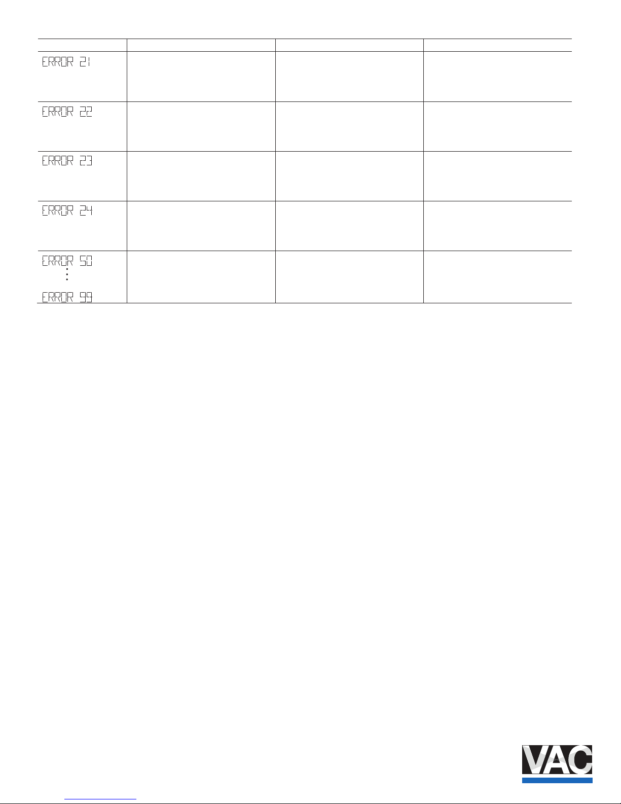
34 COI/TZIDC/TZIDC-200- EN | TZI DC, TZIDC-200
Error code Possible cause Impact Troubleshooting the Instrument
Error while processing the measured
values, pointing to an error in the
working data (RAM).
The actuator is moved to the safe
position. After approx. 5 seconds, the
positioner is automatically reset and the
RAM is reinitialized.
If the error persists even after the
positioner has been reset, the device will
need to be returned to the manufacturer
for repair.
Error during the table processing,
pointing to an error in the working data
(RAM).
The actuator is moved to the safe
position. After approx. 5 seconds, the
positioner is automatically reset and the
RAM is reinitialized.
If the error persists even after the
positioner has been reset, the device will
need to be returned to the manufacturer
for repair.
Error when verifying the checksum of
the conguration data (RAM).
The actuator is moved to the safe
position. After approx. 5 seconds, the
positioner is automatically reset and the
RAM is reinitialized.
If the error persists even after the
positioner has been reset, the device will
need to be returned to the manufacturer
for repair.
Error in the processor function registers
(RAM).
The actuator is moved to the safe
position. After approx. 5 seconds, the
positioner is automatically reset and the
RAM is reinitialized.
If the error persists even after the
positioner has been reset, the device will
need to be returned to the manufacturer
for repair.
efas eht ot devom si rotautca ehT .rorre lanretnI
position. After approx. 5 seconds, the
positioner is automatically reset.
If the error can be reproduced and
occurs in the same position after
resetting, the device must be returned
for repair to the manufacturer.
Page 35
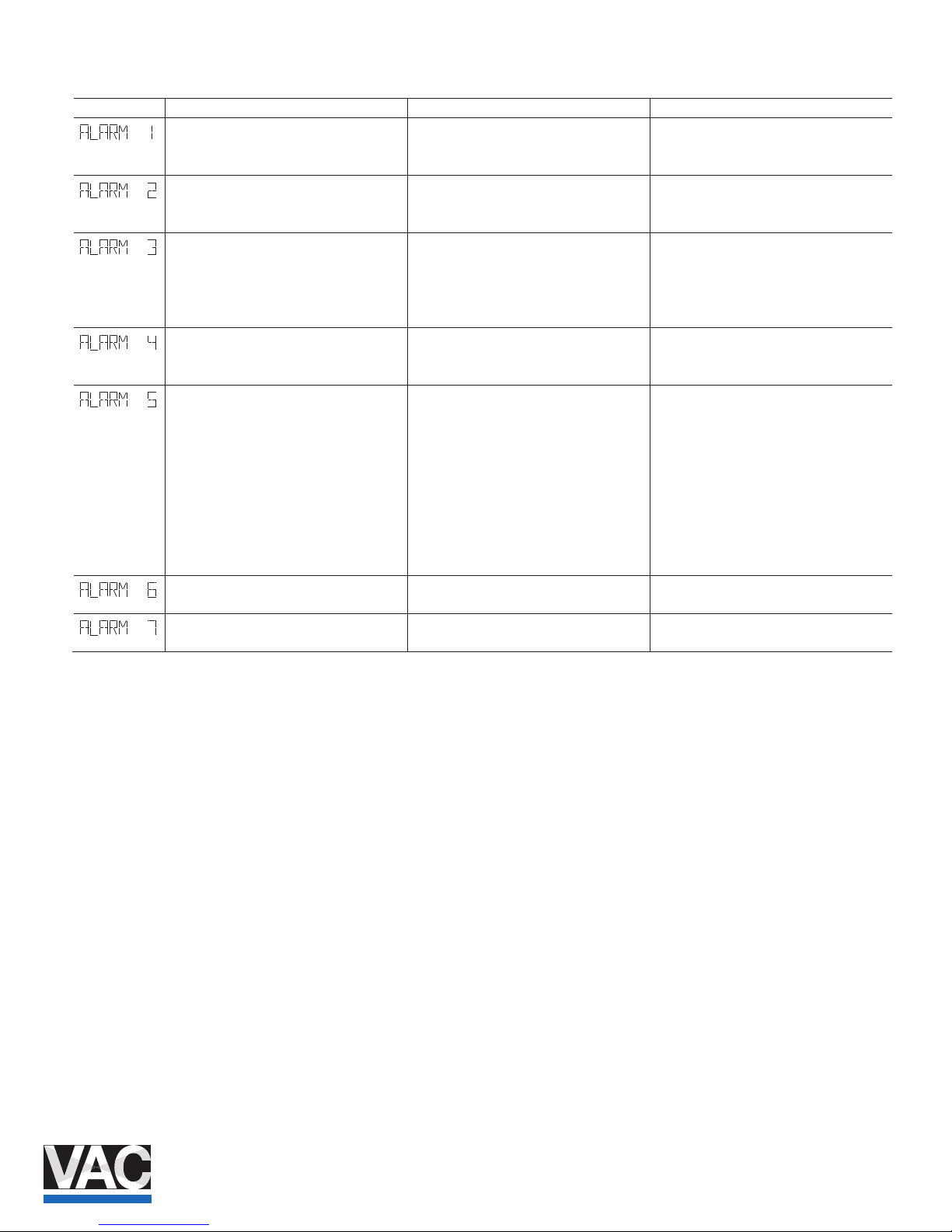
TZIDC, TZIDC- 200 | COI/TZIDC/TZIDC-200-EN 35
4.2 Alarm codes
Alarm code Possible cause Impact Troubleshooting the Instrument
Leakage between positioner and actuato r De pending on how well the leakage can be
compensated, small control actions are
required at regular intervals.
Check the piping.
The setpoint current is outside the
permissible range, i.e. it is < 3.8 mA or
> 20.5 mA.
.ecruos rewop eht kcehC -
Alarm of the zero monitor. The zero
position has shifted by more than 4%.
-
In control mode, a position outside the
valve range can only be reached by driving
to the limit stops, as the setpoint is limited
to 0 ... 100%.
Correct the mounting.
Controlling is inactive, because the device
does not operate in control mode or the
binary input is active.
The controller does not follow the setpoint. Switch to control mode or switch o the
binary input.
Positioning timed out. The settling time
needed exceeds the congured stroke
time.
None, or adaptive control is performed (in
adaptive mode).
Ensure that
— the actuator is not blocked.
— the supply air pressure is adequate.
— the given time limit is higher than 1.5
times the longest stroke time of the
actuator.
If adaption cannot run uninterruptedly for
an actuator, adaption should be switched
on until the alarm does not occur anymore
during controlling actions.
The dened limit value for the stroke
counter has been exceeded.
a aiv elbissop ylno( retnuoc eht teseR -
connected PC with suitable software).
The specied limit value for the travel
counter has been exceeded.
a aiv elbissop ylno( retnuoc eht teseR -
connected PC with suitable software).
Page 36
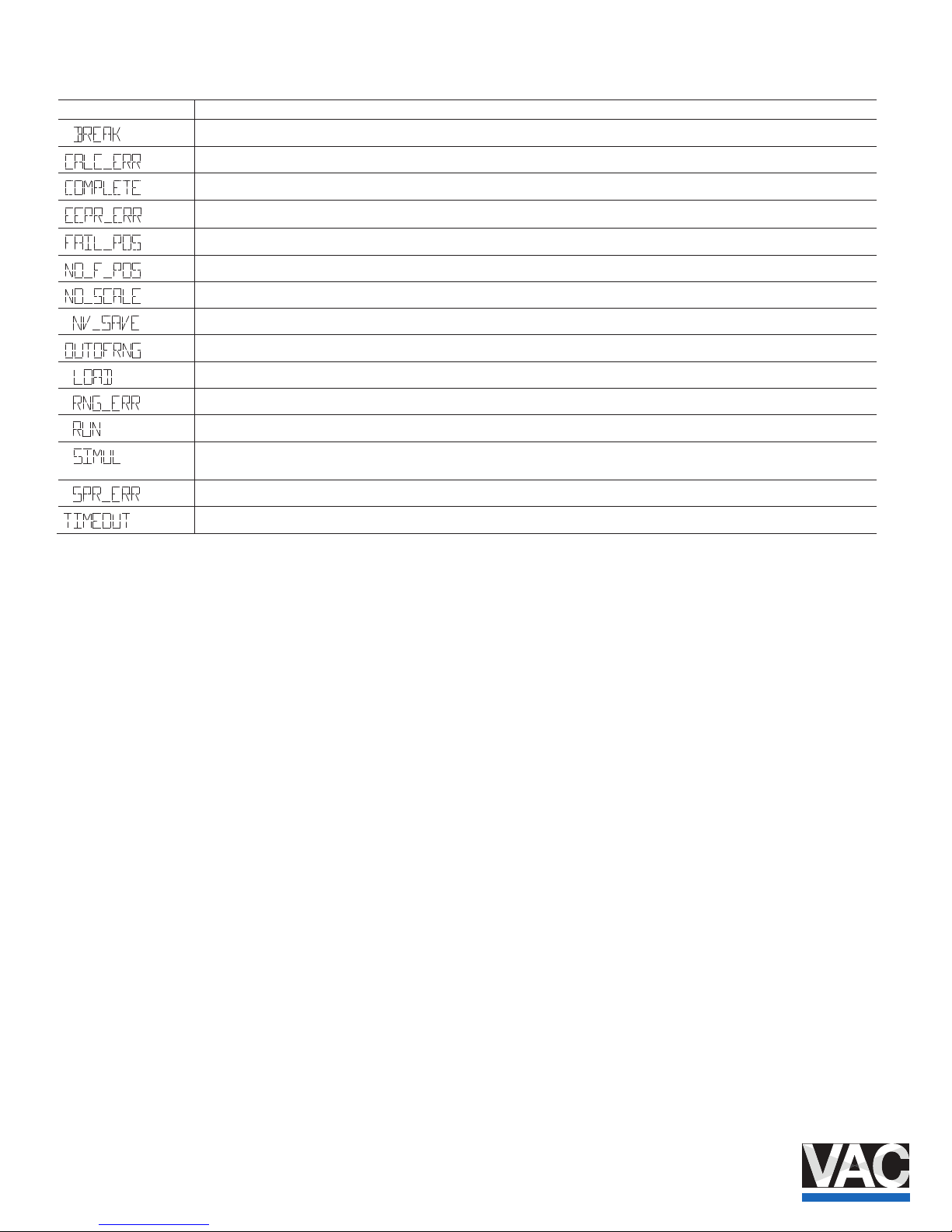
36 COI/TZIDC/TZIDC-200- EN | TZI DC, TZIDC-200
4.3 Message codes
Message codes Message description
Action stopped by operator.
Error during plausibility check.
Action completed, acknowledgment required.
Memory error, data could not be saved.
Safe position is active, action cannot be executed.
Safe position required, but not active.
Valve range limits have not yet been determined; therefore, partial Autoadjust cannot be run.
Data is saved in the non-volatile memory.
Measuring range is exceeded, Auto Adjust was automatically stopped.
Data (factory settings) are being loaded.
Less than 10 % of the measuring range is used.
Action running.
Simulation has been started externally from a PC via HART‚ Protocol; switching outputs, alarm output and analog position
feedback are no longer inuenced by the process.
Actual spring action is dierent from the adjusted one.
Time-out; parameter could not be de termined within two minutes; Autoadjust was automatically stopped.
Page 37
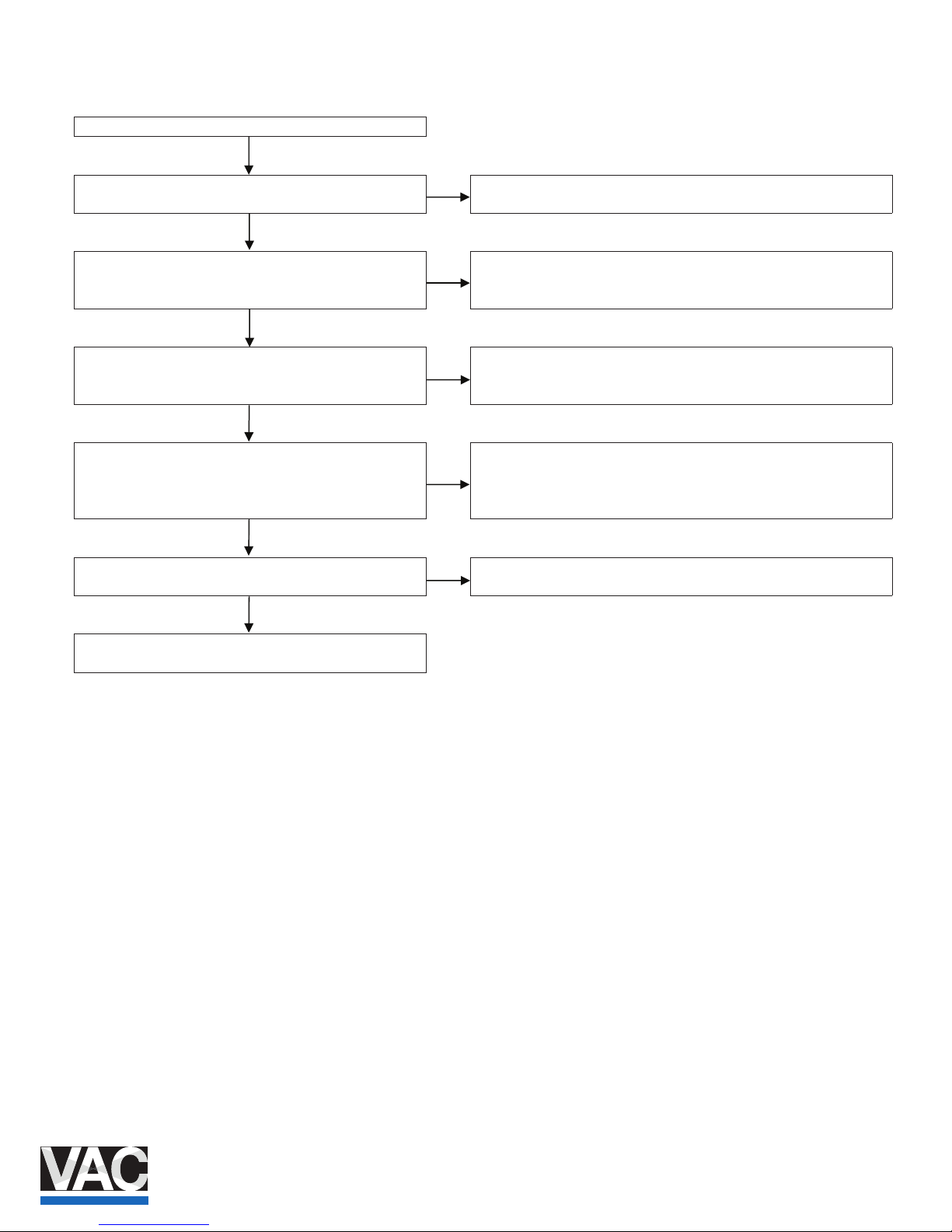
TZIDC, TZIDC- 200 | COI/TZIDC/TZIDC-200-EN 37
4.4 Error handling
4.4.1 Positioner vibrates
The positioner vibrates (oscillates) in control modes 1.0 and 1.1 .
Press the button. Is the current value stable?
No
Check power source or PLS.
Y
es
Switch the positioner to operating mode 1.2 (manual) and set it
to a position of approx. 50 % us ing the local push buttons. Is
the position stable?
No
Check the piping and actuator for leak age. If leakage is detected, send the
positioner for repair.
Y
es
Start Autostroke and save the va lues. Switch the positioner to
operating mode 1.1 .
Is the position stable?
Yes
Good job! The work activities are completed.
No
Switch the positioner to operating mode 1.0 (adaptive) for
4 to 5 hours in order to optimize the control response. Several
changes to the setpoint signal are required.
Is the positioner function stable?
Yes
Good job! The work activities are completed.
No
Increase the dead band (DEADBAND) .
Is the valve function stable?
Yes
Good job! The work activities are completed.
No
The friction of the valve is too grea t or Slipstic eect. Check the
valve.
Page 38
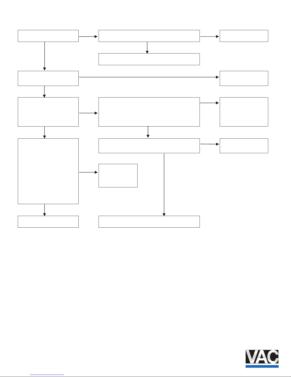
38 COI/TZIDC/TZIDC-200- EN | TZI DC, TZIDC-200
4.4.2 Positioner without function
Connect 4 ... 20 mA.
Is the display active?
No
Exchange the + and - connection wires. Now is the display
active?
Yes
Good job! The work
activities are completed.
No
Yes
Check the power source or retu rn defective positioners for
repair.
Connect compressed air. Now is it
working?
seY
Good job! The work
activities are completed.
No
Switch the positioner to operating
mode 1.2 (manual). Press the
arrow button briey. Press the
second arrow. Now is it working?
Yes
Start Autoadjust. Save parameters and switch the positioner
to operating mode 1.1 . In case of error messages, check
the mechanical conguration.
Now is it working?
No
Good job! The work
activities are completed.
No
No
No
Check the safe position for the
pneumatic output module (label on
the plastic cap) and compare with
parameter IP-Typ . The safe
position must be activated
(FAIL_POS ) before the parameter
can be changed. Save parameters.
Now is it working?
Yes
Press the arrow button to read the current value. Is the
current value correct?
Check power source or
PLS.
Good job! Work
activities are over
after starting
Autoadjust!
Yes
No
Return the defective positioner for
repair.
Switch the function for the digital input ( FUNCTION ) to
none .
Page 39

Notes
TZIDC, TZIDC- 200 | COI/TZIDC/TZIDC-200-EN 39
Notes
Page 40

Contact us
COI/TZIDC/TZIDC-200-EN 05.2016
Note
We reserve the right to make techni cal changes or
modify the contents of this document without prior
notice.
With regard to purchase orders, the agreed
particulars shall p revail. ABB does not accept any
responsi bility whatsoever for potential errors or
possible lack of information in this docume nt.
We reserve all rights in this document and in the
subject matter and illust rations contained therein.
A
ny reproducti on, disclosu re to third parties or
utilization of its contents in whole or in parts – is
forbidden without prior written conse nt of ABB.
Copyright© 2016 ABB
A
ll rights reserved
3KXE341209R4501
Original inst ruction
VALVE ACCESSORIES & CONTROLS
200 Jade Park * Chelsea, AL 35043
TEL: 205-678-0507 • FAX: 205-678-0510
vacaccessories.com
VALVE ACCESSORIES & CONTROLS
Randy Estes, Western Regional Sales Office
Cell: 713-253-7781
[email protected]
VALVE ACCESSORIES & CONTROLS
Bob Goodwin, Eastern Regional Sales Office
Cell: 518-222-1170
[email protected]
 Loading...