

VAC Renaissance Mk II Preamplifier User Manual
The VAC Renaissance Mk II
Master Control
Triode Preamplifier
Operation & Maintenance Information
Valve Amplification Company
Manual revised 06/22/2004

CAUTION
THE PREAMPLIFIER AND POWER SUPPLY CONTAIN NO USER SERVICEABLE PARTS. DO NOT
REMOVE THE BOTTOM PLATES OR CHASSIS COVERS. LETHAL VOLTAGES ARE PRESENT
WITHIN THE CHASSIS. DO NOT OPERATE THE UNITS IF THEY ARE WET.
VACUUM TUBES BECOME HOT ENOUGH TO CAUSE SERIOUS BURNS. NEVER TOUCH A TUBE
WHEN THE UNIT IS ON. IT MAY TAKE SEVERAL MINUTES FOR THE TUBES TO COOL DOWN
AFTER THE UNIT IS SWITCHED OFF. IT IS STRONGLY RECOMMENDED THAT THE TUBE COVERS
BE LEFT IN PLACE AT ALL TIMES.
THE GLASS COVERS WILL BECOME HOT IN NORMAL OPERATION. DO NOT SET OR SPRAY
ANYTHING ON THEM.
THE AMPLIFIER AND POWER SUPPLY ARE HEAVY. IT IS ADVISABLE TO HAVE ASSISTANCE IN
UNPACKING, MOVING, AND SETTING UP. BE SURE TO USE PROPER LIFTING TECHNIQUES TO
AVOID BACK STRAIN AND INJURY. BE CERTAIN TO INSTALL IT IN A SECURE LOCATION FROM
WHICH IT CAN NOT FALL OR TIP OVER.
CONTENTS
Introduction
Unpacking, Assembly/Disassembly
Installation
Inputs (back panel)
Outputs & Grounding Switch (back panel)
Operation
Fuses
Front Panel Controls
Remote Control
Replacement of Tubes
Care of Chassis
A Word About Tubes In General / Locating a Defective Tube
Warranty / Registration Form
1

INTRODUCTION
The Renaissance Mk II Preamplifier utilizes the world's finest audio preamplifier circuit and is
a unique component. Its unusual topology, premium parts, and flexibility make it a pleasure
to hear and operate.
The line stage is, in effect, a small Class A1 power amplifier, capable of driving loads as low
as a few hundred ohms. This is a stark contrast to normal preamplifiers, which claim a low
output impedance but completely collapse when asked to deliver current. The Renaissance
Mk II circuit is loafing with a normal load in the 10,000 to 200,000 ohm range, delivering an
effortless, musical performance.
There is no loop feedback and no coupling capacitors in the line section. All active elements
are triode tubes, the purest, most linear amplifying devices yet invented. Output matching
is accomplished by way of superb output transformers. As a side benefit, different output
grounding configurations are possible, optimizing performance into either balanced or
single-ended loads, and allowing ground loops to be broken.
The optional phono stage uses triode tubes operating without loop feedback. Gain is
moderately high, with a very low noise floor. Low output MC cartridges are accommodated
by means of high quality matching transformers, which contribute voltage gain without noise,
resulting in detail that emerges from a remarkably dark and neutral background.
Remote volume control is implemented via a motorized mechanical device. This provides
two major advantages. First, the control is completely intuitive to use. Second, we avoid the
sound degradation attendant with VCAs, transistor switches, and switched resistor arrays.
The main chassis is formed from aluminum to avoid magnetic interaction effects. The separate
power supply allows e.m.f. fields, switching transients, and mechanical vibration to be
isolated from the audio circuits.
The Renaissance Mk II is designed not to the latest fad but to substance, for the highest
possible sound quality. Time spent familiarizing yourself with this manual will be well
rewarded.
2
UNPACKING & ASSEMBLY
The Renaissance Mk II is shipped with the vacuum tubes installed.
Connect the DC cable from the power supply.
Tighten the two retaining screws.
NOTE:Do not plug the power supply into the wall outlet unless it is connected to the
audio chassis.
Connect the iVAC data communications cable to an associated Phi Power Amplifier if
appropriate. This allows the preamplifier to control power on, power off, and logo
illumination intensity.
Alternatively, the 12 volt trigger outputs may be used to switch on/off some brands of
power amplifiers.
3

INSTALLATION
1)Provide adequate ventilation.
2)Do not operate on carpet or any other surface that might block air flow.
3)The chassis will become warm in normal use.
4)Do not allow the chassis to touch any metal parts, such as the frame of an equipment
rack. This might create a parallel ground path that could degrade the sound.
5)Input connection is via single ended RCA jacks or XLR jacks (which can be from
balanced or unbalanced sources) - the input switch must be set appropriately or
sound quality will be compromised.
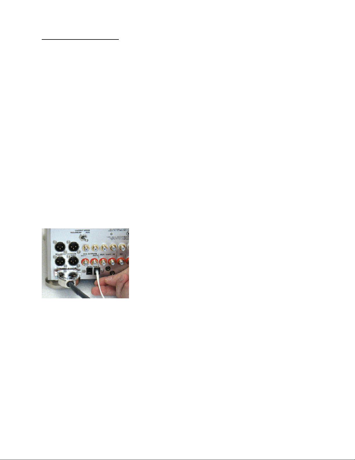
6)Output can be on RCA or XLR jacks, and can be set for balanced or unbalanced
loads, with or without ground connection at the preamplifier. IMPORTANT: READ THE
SECTION ON "OUTPUTS & GROUNDING SWITCH". Connect line level inputs (CD, Tuner,
Tape, etc.) to the appropriate RCA input jacks on the rear panel. Note: with the
exception of Phono (when fitted), all inputs are "line level"
7)Connect phono cables to the rear panel MM and/or MC inputs labeled "Phono" (both
may be used in the same system, as they are switched by a control on the front
panel). Connect the ground wire(s) from the turntable(s) or phono cable(s) to the
"Ground" terminal provided on the rear panel.
8)Connect the power cables from the power supply to the preamplifier. Be sure to
insert the connector properly, and fully tighten the locking screws.
9)Connect the input and output cables.
10)Connect the power supply to the power source indicated on the rear panel, either
100, 120, 220, or 240 volts AC. The voltage may be select by means of the
removable selector card located underneath the fuse in the power connector; to
change, remove the card and reinstall so that the desired voltage may be read. Avoid
power conditioners that float the ground pin. ALWAYS connect power cord to
component before plugging it into an AC outlet, and make sure that unit's power
switch is set to the "off" position before making the final connection. For best
performance, try to route the power cord away from signal cables.
11)Pay close attention to power quality, and be aware that different power cords can
alter the sound.
4
 Loading...