

Page 1

F
30/30
The VAC Phi Thirty/Thirty
Stereophonic Triode Power Amplifier
Operation & Maintenance Information
Valve Amplification Company
Manual issued 02/24/2003
Page 2

PLEASE READ CAREFULLY
Your Phi Thirty/Thirty is fitted with a thermal sensor circuit. It works in conjunction with the individual
indicator lights located on the front panel. It serves two purposes:
1)If the idle current of a 300B output tube should drop below nominal limit, the light
corresponding to that tube will light green. This indicates that the tube should be replaced
at your convenience, but it is safe to continue operating the amplifier.
The exact idle current of each tube may be tested by means of the meter and the test
switches. Typical readings are near the dot in the center of the meter. When no test switch
is selected, the meter indicates the incoming ac voltage (wall voltage).
Note: These lights will also be green when the amplifier is first switched on, and will
extinguish when the bias resistors have reached normal operating temperature after several
minutes. The threshold between green and no illumination is not precise; do not be overly
concerned if some positions take longer to extinguish. The condition of individual tubes
may be checked with the built in meter.
Note: a strong air current could cause the lights to remain green even in normal operation.
2)Should any output tube draw excessive idle current (a “run away” tube or a tube
with an internal short):
A)The high voltage supply in the amplifier will shut down automatically.
B)The light corresponding to the bad 300B tube will glow red. The red light will stay
on until the power switch is turned off. This tube must be replaced.
The lights for the other tubes will show green after a few minutes...this should be
disregarded.
This protection feature normally will operate with much greater speed than the AC line fuse,
and provides a high degree of protection against elevated temperature or fire due to a
major failure in an output tube. However, completely failsafe methods are not possible. As
with any high power electrical device, do not leave the amplifier running unattended. Turn
the amplifier off immediately if you smell any strong odor, or if you see any parts glowing
orange through the ventillation holes between the tubes.
To minimize difficulties, always source the highest quality tubes, avoiding inexpensive or generic
300B tubes. We recommend obtaining replacement tubes from VAC, stating that they are for use
in the Phi Thirty/Thirty.
Page 3

CAUTION
THE AMPLIFIER AND POWER SUPPLY CONTAIN NO USER SERVICEABLE PARTS. DO NOT REMOVE THE
BOTTOM PLATES OR CHASSIS COVERS. LETHAL VOLTAGES ARE PRESENT WITHIN THE CHASSIS. DO
NOT OPERATE THE UNITS IF THEY ARE WET.
VACUUM TUBES BECOME HOT ENOUGH TO CAUSE SERIOUS BURNS. NEVER TOUCH A TUBE WHEN
THE UNIT IS ON. IT MAY TAKE SEVERAL MINUTES FOR THE TUBES TO COOL DOWN AFTER THE UNIT
IS SWITCHED OFF. IT IS STRONGLY RECOMMENDED THAT THE TUBE COVERS BE LEFT IN PLACE AT ALL
TIMES.
THE TUBE COVERS WILL BECOME HOT IN NORMAL OPERATION. DO NOT SET OR SPRAY ANYTHING
ON THEM.
THE AMPLIFIER AND POWER SUPPLY ARE HEAVY. IT IS ADVISABLE TO HAVE ASSISTANCE IN
UNPACKING, MOVING, AND SETTING UP. BE SURE TO USE PROPER LIFTING TECHNIQUES TO AVOID
BACK STRAIN AND INJURY. BE CERTAIN TO INSTALL IT IN A SECURE LOCATION FROM WHICH IT CAN
NOT FALL OR TIP OVER.
INDEX
Introduction
Unpacking & Assembly
Installation
Input connectors
Operation
Illuminated Logo
Installing New Output Tubes
Checking Output Tube Condition
Replacement of Low Level Tubes
Care Of Chassis
Tips and Advice
A Word About Tubes in General
Output Tubes
Low Level Tubes
Impedance Matching
Feedback
Grounding
Tuning Your System
Specifications
Footnotes
Warranty & Registration Form
1
Page 4

INTRODUCTION
The Phi Thirty/Thirty is a unique power amplifier. It allies purist amplifying devices with the power and
solidity required to control modern audiophile loudspeakers. Extreme linearity is achieved without
resorting to loop negative feedback, for a more natural, dimensional sound.
The most noticeable feature of this amplifier is the 300B filamentary triode output tube. Originally
designed by Western Electric in 1935 (Footnote 1), it has several extremely desirable features that
have kept it in continuous production since that time. An examination of its dynamic curves (Figure
1) reveals it to be a naturally linear device, more so than any transistor device. It gives this superb
performance with voltages on the order of 450 VDC, not the 1000-1500 VDC required by other
output triodes like the 211 or 845. This lower voltage and lower output impedance allows superior
output transformer design, control of the loudspeaker, and safety.
Each 300B tube has its own separate heater power supply and independent cathode self-bias
network. This has several major advantages. No user adjustment of any kind is necessary to maintain
proper balance of the amplifier. The stabilizing action of this technique upon the idle current (bias
point) of each tube is exceptionally strong, and self corrects for large mismatches among tubes or
drift with age. This circuit also results in real-world output capability much greater than the testbench rating would indicate (Footnotes 2,3,4).
A total of four 300B are used in Class A1; that is, they are not operated into cutoff (as in Class AB
or B) or driven into grid current (suffix “2" operation) in normal operation. This is the purest, most
linear technique known.
The input circuitry of the Phi Thirty/Thirty is derivative of the unique Williamson circuit, which
provides pure, direct coupled, inherently balanced input amplification and phase splitting. Type
6SN7/5692 octal twin triodes do the honors.
The superb VAC output transformers provide superb voltage/current translation, allowing
impedances from eight ohms to as low as one ohm to be driven.
The main chassis is machined from thick aluminum. The separate power supply allows e.m.f. fields,
switching transients, and mechanical vibration to be isolated from the audio circuits. The high
voltage supply dual choke pi filtering for extremely low noise.
The Phi Thirty/Thirty is designed not to the latest fad but to substance, for the highest possible
sound quality. Time spent familiarizing yourself with this manual will be well rewarded.
2
Page 5

UNPACKING & ASSEMBLY
The vacuum tubes and glass covers are packed individually to prevent damage, and must be fitted
to the amplifier before installation can proceed.
Remove the four screws that secure the aluminum top frame to the chassis
pillars using the tool provided. Turn counterclockwise to remove.
Wear the supplied cotton gloves to minimize the chance of fingerprinting
the nickel plated chassis. Wipe any oils off immediately.
Take care to prevent the tool from scratching the chassis.
Remove the top frame.
From each of the four columns remove the tape, which prevented the
nylon setscrews from coming loose during shipment.
Slide the side and rear glass plates into the pillars’ channels.
Note that the rear glass is slightly wider than the side glasses.
The glass will not go all the way to the chassis top, but has a gap at the
bottom for air flow.
Take care not to scratch or break the glass.
3
Page 6

The front glass has the etched VAC logo. Install this between the front pillars.
Take great care not to scratch this glass.
The front glass fits into a small channel in the front plate.
Tighten the white nylon setscrews that secure the rear glass and side
glasses. Turn clockwise to tighten.
There are four setscrews for each glass plate.
Do not tighten the setscrews for the front glass yet.
Install the six aluminum blocks at the top of the rear glass and side glasses.
If there is a ‘dimple’ in the block, it should face the outside of the amplifier.
Tighten the metal setscrews that secure each block using the allen key
supplied. Turn clockwise to tighten.
Replace the aluminum top frame.
Ensure that the front glass fits into the groove in the top frame.
Ensure that the top frame sits flush in the pillars.
Replace the four screws that secure the top frame. Turn clockwise to
tighten.
(Note: photo does not show the tubes or glass, which should be installed
by this time.)
4
Page 7
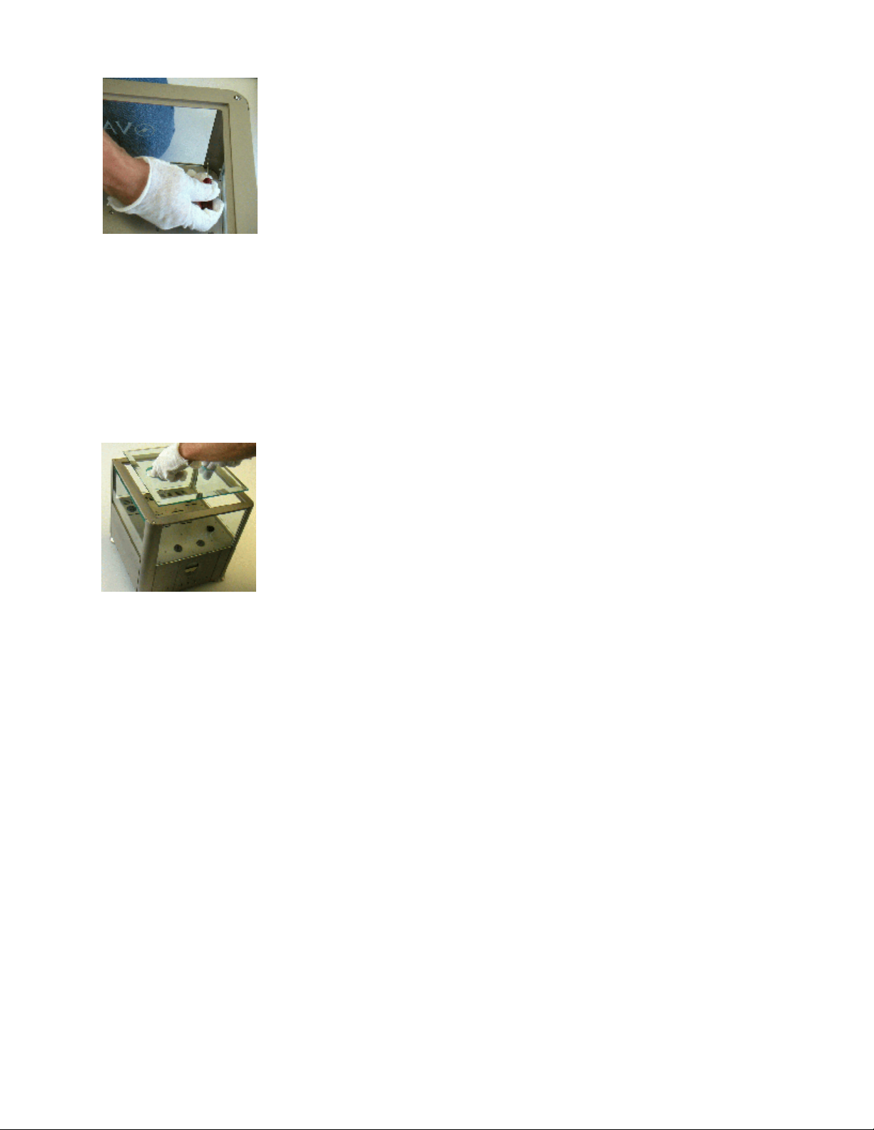
Tighten the four white nylon setscrews that secure the front glass using the
tool provided. Turn clockwise to tighten.
Do not over tighten.
Install the vacuum tubes.
Each tube or its box has a “V” number, which corresponds to the labels on the top plate of the
amplifier; these indicate where each tube should be installed.
Fit each tube into the matching socket, first
When inserting and removing tubes, handle them by their bases, not by their glass bulbs.
Note that there is a locator pin on the octal (eight contact) tubes that indicates proper alignment.
For the 300B tubes, two of the pins are of larger diameter, so that the tube will only fit into the
socket one way.
Set the beveled glass top into the aluminum top frame, oriented so that the
two holes are on the left and right side.
removing
any sticker from the amplifier and/or the tube.
To prepare a Phi 30/30 for shipment, follow these steps in reverse order.
When loosening the metal and nylon setscrews, be careful not to back them all of the way out of
the holes! If a metal screw falls into the amplifier, contact VAC for service directions.
NOTE:Do not remove and connect input cables or speaker cables while is amplifier is running.
Doing so risks damage to your loudspeakers or the amplifier.
Do not operate the amplifier without a loudspeaker or load resistor attached.
5
Page 8
INSTALLATION
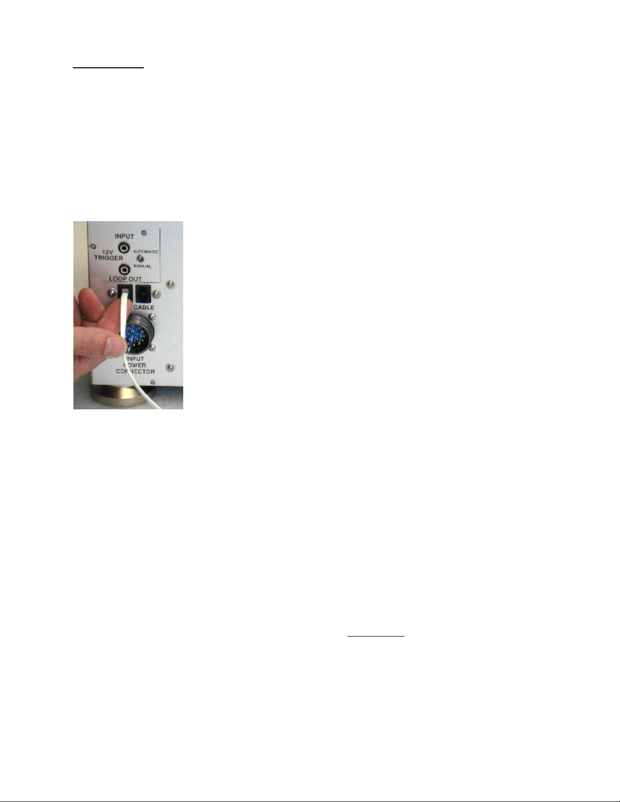
01)Attach the cord from the power supply to the amplifier and screw the connector collar
down fully; this takes many turns.
02)Select either the “4 ohm” connector or the “8 ohm” connector to suit your loudspeaker.
Connect the speaker cables; the black lead goes to “-“, the red lead goes to “+”. For further
information see Tips & Advice: Impedance Matching.
03)Set the input type switch to XLR or RCA, to match the source and cables. Note: using the
supplied adapter, an RCA input can be run into the XLR balanced jack. In such cases, ground
isolation is created, which in some systems will quell hum and/or buzz due to system
ground loops.
04)For traditional stand alone operation, set the 12 volt trigger switch
to “manual”. To use a 12 volt trigger to control power on/power
off, set the switch to “automatic”. Also select “automatic” when
connecting to the iVAC data buss of the Phi 2.0 Master Control
Preamplifier.
05)Provide adequate ventilation - allow at least 3 inches above and to each side.
06)Do not place in a completely enclosed cabinet. Do not stack other equipment on top of
the VAC unit.
07)Do not operate on carpet or any other surface that might block air flow.
08)The chassis and glass will become hot in normal use.
09)Do not allow the chassis to touch any metal parts, such as the frame of an equipment rack.
This might create a parallel ground path that could degrade the sound of your system.
10)Connect the power supply to the power source indicated on the voltage selector card
(visible by the main fuse), either 100, 120, 220, or 240 volts AC. The voltage may be select
by means of the removable selector card located behind the fuse in the power connectors.
Remove the cards and reinstall so that the desired voltage may be read; be certain to
change the fuse to the correct value.
11)Avoid power conditioners that float the ground pin.
12)Power requirements are approximately 500 watts per channel. Pay close attention to power
quality, and be aware that different power cords can alter the sound.
6
Page 9
INPUT CONNECTORS
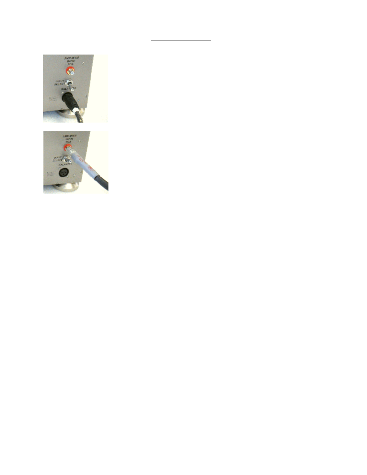
XLR connection, balanced or single-ended, are made to the XLR jacks on the
rear panel.
The INPUT SELECT toggle switches is set to the BALANCED position.
The XLR connection follows the EIA “pin 2 hot” polarity convention.
RCA (single ended) connection normally is made to the RCA jacks on the
rear panel. This is the “direct in” mode.
The INPUT SELECT switches is set to “RCA”
NOTE:Do not remove and connect input cables or speaker cables while is amplifier is running.
Doing so risks damage to your loudspeakers or the amplifier.
Do not operate the amplifier without a loudspeaker or load resistor attached.
7
Page 10

OPERATION
By time delay, sound will begin approximately 60 seconds after turn on.
As with all high fidelity products, the sound characteristic of the VAC changes somewhat as it warms
up. Best sound will be achieved after about one hour of operation. We advise against leaving the
equipment on at all times for safety reasons (see Safety Notice at the front of this manual), and
because of the attendant acceleration of output tube wear and power consumption. Life of the
output tubes averages 5,000 to 10,000 hours.
Any time that the VAC Power Amplifier has not been used for a few weeks the sound may be
different. This is also normal for high resolution audio equipment. Optimum sound should return
after a few hours of operation, preferably with an audio signal. Refer to the discussion of break in
contained in the INTRODUCTION section of this manual for further information.
Please note that although your VAC System has been run for 48 hours at the factory, the break-in
time of high resolution audio equipment is infuriatingly long. The Phi sound will continue to season
for approximately 200 hours. The early sound of the amplifier will be less extended, dynamic, and
coherent. Then the sound will improve noticeably, followed by a period of darker sound, finally
giving way to the desired musicality. Patience is a virtue.
Also be aware that many components display the need for a new break in period after being
transported in unheated cargo aircraft.
8
Page 11

INSTALLING NEW OUTPUT TUBES
Output tubes are type 300B. Replacement 300B output tubes should be purchased from VAC. It
is important that the tubes be checked for any tendency to mechanical or electrical shorts (see
Safety Notice at the front of this manual). It is desirable that tubes be in matched quartets for each
channel, and be close to the "bogey" values for the major parameters. Make certain that each tube
fits firmly in its socket.
ALL POWER MUST BE OFF. Remove the top glass and the old tubes after they have cooled down
(THE COVER BECOMES QUITE HOT IN NORMAL USE; TUBES BECOME HOT ENOUGH TO CAUSE
SERIOUS BURNS WHEN IN OPERATION AND MAY TAKE SEVERAL MINUTES TO COOL DOWN). Install
the new tubes firmly and fully in the sockets, observing that the tube will only fit into the socket in
one orientation, as two of the pins are of larger diameter. Do not use excessive force. Replace the
top glass cover before operating the amplifier.
A slight violet glow in the tube is not cause for concern. If at any time the plate (the outermost metal
structure) of the output tubes begins to glow bright orange or red SWITCH OFF IMMEDIATELY. The
red glow indicates that the tube is "running away", being destroyed by conducting excessive
current. Tubes may run away for several reasons:
1)The tube is not fully inserted in the socket.
2)The tube fits loosely in the socket and thus can not make correct contact. Such a tube is
unusable.
3)The tube is defective.
In the event that trouble is encountered check connections and/or try another tube. Stop if the
problem persists and consult with your dealer or VAC.
Switch off immediately if any part visible through vent slots at the back of the chassis glows orange.
See Safety Notice at the front of this manual.
For further information, refer to Tips & Advice: Tubes in General and Tips & Advice: Output Tubes.
9
Page 12

CHECKING OUTPUT TUBE CONDITION
As described at the beginning of this manual, the Phi 30/30 is equipped with the 300B Sentry
circuit, which continuously monitors each output tube to ensure that it is operating within normal
limits. Each tube has a corresponding indicator light on the front panel.
A green indicator light will be seen until the amplifier warms up, and when a tube’s idle current is
less than normal. It is safe to use your amplifier under these conditions, but the tube should be
replaced at your convenience. The threshold between green and no illumination is not precise;
do not be overly concerned if some positions take longer to extinguish. The condition of individual
tubes may be checked with the built in meter.
By operating the test switches below the light, the meter will display the exact idle current in the
tube. Be certain to stop the music before making the reading. Typically, the meter will indicate near
the dot at the center of the scale. A lower indication will also be observed if your power voltage
is low.
If a strong air current is blowing on the amplifier, it is possible that a tube within the normal current
range will still display the green indicator light.
If a tube draws excessive current, the indicator light will turn red and the high voltage supply will
shut down. This tube should be replaced before using the amplifier.
Please note that operating the amplifier without adequate ventilation will cause the red indicator
lights to come on and the amplifier to shut off. Operating the amplifier on a thick carpet will cause
this, and is not safe.
10
Page 13

REPLACEMENT OF LOW LEVEL TUBES
All power must be switched off. Allow tubes to cool down. Remove the top glass cover. Remove
and replace with new tubes of the appropriate types, noting the location of holes in the socket and
pins of the tubes. Replace the glass cover before operating the amplifier.
Replacement tubes are available from VAC and other sources.
For further information, refer to Tips & Advice: A Word About Tubes in General and Tips & Advice:
A Word About Low Level Tubes.
CARE OF CHASSIS
VAC chassis are machined aluminum for superior electromagnetic performance. The main chassis
is finished in nickel plating, which is kept waxed to prevent oxidation, staining, or discoloration of
the nickel. The power supply chassis is finished in durable textured gloss paint. Cleaning the units
with a damp cloth WHILE THE AMP IS SWITCHED OFF AND UNPLUGGED should suffice. Do not get
cleaning solutions onto or into the tube sockets. A light coat of wax should be applied periodically
to the nickel surfaces, taking care that the amplifier is cool and unplugged.
11
Page 14

TIPS & ADVICE SECTION
A Word About Tubes in General
It is true that each brand of tube sounds different in a particular high resolution circuit. This is
because no two manufacturers make a tube type in quite the same way, and the central tendencies
of the performance parameters will differ slightly with each maker. To emphasize the point, examine
the plate structure of any two 6SN7 from different manufacturers will probably find that they may
not even the same shape and size. (Be careful here, as often a tube is made by a firm other than
indicated on its label. In the heyday of tubes it was common to crossbrand between major labels,
such as GE and RCA. Today many labels do not manufacture their tubes at all, including Gold Aero
and RAM.)
This sonic variability may at first seem a liability, but further thought will reveal that it is an advantage,
just like the ability to adjust VTA on a tone arm. The owner of a tube amplifier can select those tubes
which sound like the real thing in his/her specific system. Of course, if the manufacturer you prefer
is rare you may want to purchase a few spare tubes for the future.
How long should tubes last? It has long been known in professional circles (and probably now
forgotten) that a tube such as the 12AX7 will display better performance characteristics after two
years of continual operation than when it was new. In normal use it is not unusual for a low level
tube to last 5 years or longer. Output tubes are another story, as they are continually providing
significant amounts of current. Here the sound is your best guide. Certainly a tube should be
replaced when its emission is significantly down or its transconductance is substantially out of
specification. In normal use, output tubes will last at least 2 years and perhaps more than 5 years.
It is normal to see a slight violet glow in a power tube such as a 300B or EL34. However, a vivid
violet indicates excess current flow through the tube and should be investigated.
VAC can test tubes for concerned customers.
12
Page 15

Tips: Output Tubes
Your VAC Amplifier uses the 300B or 300A filamentary triode. It is strongly recommended that
replacement tubes be purchased only from VAC. If, however, you want to customize the sound
to your tastes, be aware that as with interconnects and speaker cables, each tube manufacturer's
300B tends to have a distinct sound, as well as its own reliability profile.
Tips: Low Level Tubes
The Voltage Amplifier/Phase Splitter and driver tubes in the Phi Thirty/Thirty is the 6SN7 medium mu
octal twin triode. Your amplifier is fitted with the current production VAC Tested 6SN7 from China,
which we find superior to the NOS types we have tried. There are dozens of versions of this tube
available in new old stock (NOS) from a variety of sources. It would be impossible to characterize
them all.
Other equivalent type numbers are 5692, 13D2, B65, ECC32, QA2408, QB65, and CV1988.
Tubes V1 and V2 should be transconductance matched, and tubes V3 and V4 should be
transconductance matched; this minimizes distortion.
We strongly recommend obtaining tubes as sets from VAC.
13
Page 16

Tips: Impedance Matching
We strongly suggest that you experiment with the three available impedance connections for the
best sonic match with your system. Since no loudspeaker represents an unchanging impedance at
all frequencies, it is impossible to assert with certainty which output tap is appropriate to use. In
many systems an amazing difference in sound will exist between the various impedance taps.
The available connections on your Phi Thirty/Thirty are:
Labeled Use with speakers of
8 ohms4 to 16 ohms
4 ohms1 to 6 ohms
Since the impedance of most loudspeakers vary over a wide range experimentation is essential.
Most speakers have a rated impedance of 4 or 8 ohms. We recommend starting with the 8 ohm
connection; after you know the sound if that connection, try the 4 ohm connection. Choose the
connection that sounds best to your ears.
If you bi-wire your system (run separate speaker leads from the amplifier to the high and low
frequency transducers) you may discover that two different impedance taps work best.
Contrary to popular misconception, no power is lost due to unused output taps.
For more information consult VAC Technical Monograph 90-9.
14
Page 17

Tips: Audio Grounding
Systems incorporating single-ended interconnect cables (“RCA cables”) are prone to a problem
known as “ground looping”, which can result in extraneous hums and buzzes audible through the
loudspeaker. If this occurs in your system, you have two options: 1) to work to minimize the ground
loop, or 2) use the balanced input via the supplied adapter to break the ground loop.
To minimize the buzz using the normal RCA input jack, there are several steps you can take:
1)Use the shortest interconnects possible.
2)Use interconnects with good shielding properties.
3)Keep the two amplifiers and their cables as close together as possible.
4)Use the same AC outlet for both channels.
5)Keep the AC cords away from the audio cables.
6)Keep the power supply chassis away from audio chassis and audio cables.
7)Try different ground settings on your preamplifier, if it has them. For example, the VAC
Signature, Phi, and Renaissance preamplifiers may be set to “ungrounded” or “XLR” audio
modes.
8)The use of cheater plugs is not recommended and poses as safety hazard.
The simplest approach is to run the RCA cable into the balanced XLR jack via the supplied adapter.
The balanced input is buffered by a wideband transformer, and effectively breaks ground loops
in most systems.
15
Page 18

SPECIFICATIONS
The VAC Phi Thirty/Thirty has been developed with the critical ear as the major arbiter of quality, with
both conventional and unique measurements providing insight and guidance as necessary. The lack
of emphasis on measurements is due to the fact that engineering's arsenal of equipment and
techniques do not operate on the pattern recognition principals that control human perception of
sound.
In the immortal words of Daniel von Recklinghausen, if it measures good and sounds bad, it is bad.
If it measures bad and sounds good, you've measured the wrong things.
For those concerned with test bench performance, the following describes typical measured
performance when operated at 120 VAC, 60 Hz.
Power Output:32 watts continuous average power at 1 kHz with less than 2% THD into 4
ohms connected to the 8 ohm tap, both channels driven.
Frequency Response:down 0.5 dB at 7 Hz and 30 kHz, ref 0 dB = 1 watt @ 1 kHz.
down 3.0 dB at 3.5 Hz and 115 kHz, ref 0 dB = 1 watt @ 1 kHz.
Absolute Polarity:Does not invert absolute phase.
FOOTNOTES:
1.Tube Manufacturing at Western Electric: The WE 300, Attila R. Balaton. Journal of the Audio
Engineering Society, Vol.37, No.11, November 1989, pages 949-958.
2.The Low-Loading Self-Biased Amplifier, L.B.Dalzell. Audio, December 1959, pages 19-21.
3.The Fixed-Bias Story (Is Fixed Bias Really Better?), Herbert Ravenswood. Radio-Electronics,
February 1958, pages 47-49.
4.Philips Hi Fi Amplifier Circuits. Published in Holland, 1958.
5.WE 300B. MJ Audio Technology, 1992/5, pages 213-215.
16
Page 19

WARRANTY
Your equipment is warranted for a period of thirty (30) days from the date of purchase. In addition, if the
registration form is received by VAC along with a copy of your sales receipt from an authorized VAC dealer
within this thirty days, a service contract will be extended to cover your equipment for three (3) years (tubes
excepted). This warranty applies only to units sold in the United States of America through authorized VAC
dealers. It covers factory service and standard return shipping. For warranty information outside of the U.S.
contact the importer of VAC equipment for your country. Units sold outside of the U.S. should still be
registered with VAC.
Your questions and comments are always welcome. Contact:
Valve Amplification Company
1731 Northgate Boulevard
Sarasota, FL 34234
Telephone (941) 359-2066Fax (941) 359-2057
[email protected]
_____________________________
Detach and mail to the address above as soon as possible.
____________________________
Phi Thirty/Thirty Registration Form
Name________________________________________________________________________
Address________________________________________________________________________
________________________________________________________________________
Telephone_______/_______-_____________e-mail __________________________________
Dealer name________________________________City ________________________________
Salesperson___________________ Purchase date ____________Serial Number ________________
How did you first learn of VAC products? ____________________________________________________
What other brands/models did you consider? _________________________________________________
_____________________________________________________________________________________
What made you decide on the VAC? _______________________________________________________
_____________________________________________________________________________________
What else would you like us to know? _______________________________________________________
_____________________________________________________________________________________
_____________________________________________________________________________________
Optional:
What magazines do you read regularly?________________________________________________________
What are your hobbies (besides filling in warranty cards)? _______________________________________
What are your favorite types of music? ______________________________________________________
_____________________________________________________________________________________
On what format? (CD, LP, DVD, SACD, MP3, etc.) ______________________________________________
 Loading...