

VAC PHI-2.0 Owners manual
F
2.0
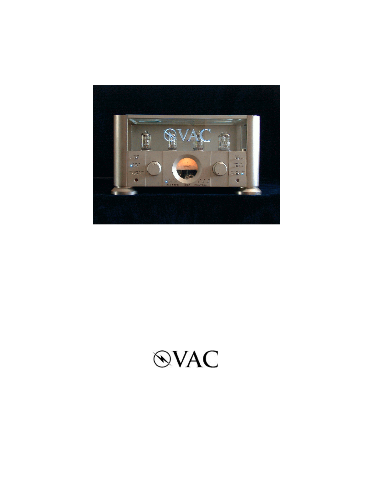
The VAC Phi 2.0 Master Control
Triode Preamplifier
Operation & Maintenance Information
Valve Amplification Company
Manual issued 02/24/2003
Revised 05/16/2005

CAUTION
THE PREAMPLIFIER AND POWER SUPPLY CONTAIN NO USER SERVICEABLE PARTS. DO NOT
REMOVE THE BOTTOM PLATES OR CHASSIS COVERS. LETHAL VOLTAGES ARE PRESENT
WITHIN THE CHASSIS. DO NOT OPERATE THE UNITS IF THEY ARE WET.
VACUUM TUBES BECOME HOT ENOUGH TO CAUSE SERIOUS BURNS. NEVER TOUCH A TUBE
WHEN THE UNIT IS ON. IT MAY TAKE SEVERAL MINUTES FOR THE TUBES TO COOL DOWN
AFTER THE UNIT IS SWITCHED OFF. IT IS STRONGLY RECOMMENDED THAT THE TUBE COVERS
BE LEFT IN PLACE AT ALL TIMES.
THE GLASS COVERS WILL BECOME HOT IN NORMAL OPERATION. DO NOT SET OR SPRAY
ANYTHING ON THEM.
THE AMPLIFIER AND POWER SUPPLY ARE HEAVY. IT IS ADVISABLE TO HAVE ASSISTANCE IN
UNPACKING, MOVING, AND SETTING UP. BE SURE TO USE PROPER LIFTING TECHNIQUES TO
AVOID BACK STRAIN AND INJURY. BE CERTAIN TO INSTALL IT IN A SECURE LOCATION FROM
WHICH IT CAN NOT FALL OR TIP OVER.
CONTENTS
Introduction
Unpacking, Assembly/Disassembly
Installation
Inputs (back panel)
Outputs & Grounding Switch (back panel)
Operation
Fuses
Front Panel Controls
Remote Control
Replacement of Tubes
Care of Chassis
A Word About Tubes In General / Locating a Defective Tube
Warranty / Registration Form
1

INTRODUCTION
The Phi Preamplifier is the world's finest audio preamplifier and an absolutely unique
component. Its unusual topology, premium parts, and flexibility make it a pleasure to hear
and operate.
The line stage is, in effect, a small Class A1 power amplifier, capable of driving loads as low
as a few hundred ohms. This is a stark contrast to normal preamplifiers, which claim a low
output impedance but completely collapse when asked to deliver current. The Phi circuit
is loafing with a normal load in the 10,000 to 200,000 ohm range, delivering an effortless,
musical performance.
There is no loop feedback and no coupling capacitors in the line section. All active elements
are triode tubes, the purest, most linear amplifying devices yet invented. Output matching
is accomplished by way of superb output transformers. As a side benefit, different output
grounding configurations are possible, optimizing performance into either balanced or
single-ended loads, and allowing ground loops to be broken.
The optional phono stage uses triode tubes operating without loop feedback. Gain is
moderately high, with a very low noise floor. Low output MC cartridges are accommodated
by means of high quality matching transformers, which contribute voltage gain without noise,
resulting in detail that emerges from a remarkably dark and neutral background.
Remote volume control is implemented via a motorized mechanical device. This provides
two major advantages. First, the control is completely intuitive to use. Second, we avoid the
sound degradation attendant with VCAs, transistor switches, and switched resistor arrays.
The main chassis is machined from thick aluminum. The separate power supply allows e.m.f.
fields, switching transients, and mechanical vibration to be isolated from the audio circuits.
The high voltage supply dual choke pi filtering for extremely low noise.
The Phi 2.0 is designed not to the latest fad but to substance, for the highest possible sound
quality. Time spent familiarizing yourself with this manual will be well rewarded.
2
UNPACKING & ASSEMBLY
The Phi 2.0 is shipped with the vacuum tubes and glass covers installed. Should the need
ever arise, the following directions illustrate how to install the glass; follow these steps in
reverse order to remove the glass.
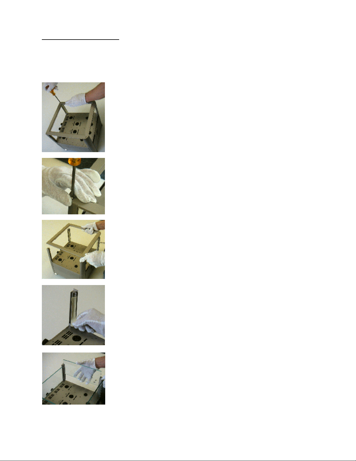
Remove the four screws that secure the aluminum top frame to the
chassis pillars using the tool provided. Turn counterclockwise to
remove.
Wear the supplied cotton gloves to minimize the chance of
fingerprinting the nickel plated chassis. Wipe any oils off immediately.
Take care to prevent the tool from scratching the chassis.
Remove the top frame.
From each of the columns remove the tape, which prevented the
nylon setscrews from coming loose during shipment.
Slide the side glass plates into the pillars’ channels.
The glass will not go all the way to the chassis top, but has a gap at
the bottom for air flow.
Take care not to scratch or break the glass.
3
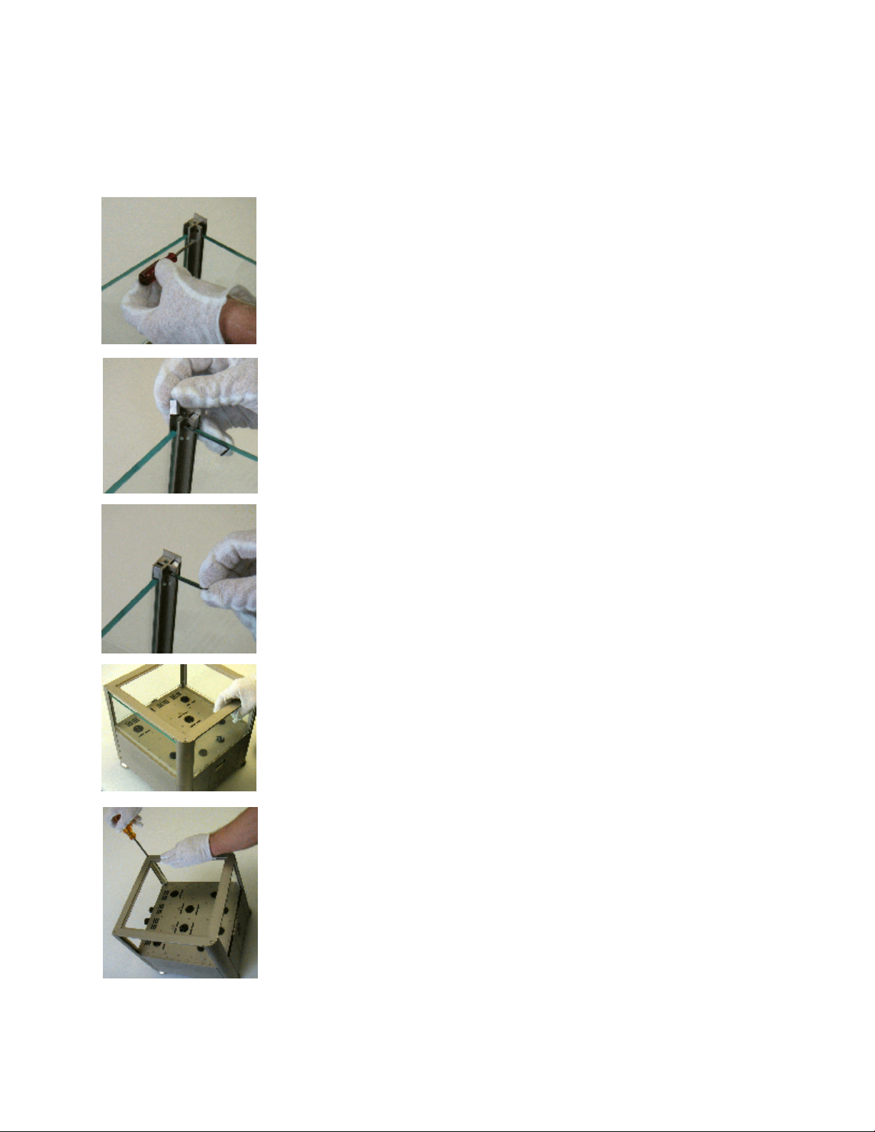
The front glass has the etched VAC logo. Install this between the front pillars.
Take great care not to scratch this glass.
The front glass fits into a small channel in the front plate.
Tighten the white nylon setscrews that secure the rear glass and side
glasses. Turn clockwise to tighten.
There are four setscrews for each glass plate.
Do not tighten the setscrews for the front glass yet.
Install the aluminum blocks at the top of the side glasses.
If there is a ‘dimple’ in the block, it should face the outside of the
amplifier.
Tighten the metal setscrews that secure each block using the allen key
supplied. Turn clockwise to tighten.
Replace the aluminum top frame.
Ensure that the front glass fits into the groove in the top frame.
Ensure that the top frame sits flush in the pillars.
Replace the four screws that secure the top frame. Turn clockwise to
tighten.
(Note: photo does not show the tubes or glass.)
4
 Loading...