

Page 1

USER MANUAL MANUEL DE L’UTILISATEUR
PDU
PDU14B15A0U
PDU14B15A1U
Page 2

TABLE OF CONTENTS
1 Getting Started
Package Includes
2 Setup
Horizontal Rack Mounting (1U model only)
Vertical Rack Mounting (0U & 1U)
Keyhole Mounts (0U models only)
6” Plate for Vertical Rack Mounting (0U model only)
Cord Retention Tray Installation
Electrical Installation
3 Product Features
4 Technical Specications
Basic Series (1U)
Basic Series (0U)
5 Safety and Warnings
Page 3

GETTING STARTED
Package includes
Included Accessories
PDU14B15A0U PDU14B15A1U
Cord Retention Tray
Horizontal Rack
Mounting Brackets
Bracket Mounting Screws
M4 x 6 (4 pcs)
Cord Retention Tray
Mounting Screws
M3 x 6 (4 pcs)
Keyhole Mounting Pegs (2 pcs)
with Screws M4 x 6 (2 pcs)
(For 0U models only)
Cable Ties
(For Cord Retention Trays)
Grounding Screw
M4 x 6 (1 pc)
6" Plate for Vertical Rack Mounting
(for 0U models only)
BackFront
Vertical Rack
Mounting Brackets
Page 4

SETUP
Horizontal Rack Mounting (1U model only) Vertical Rack Mounting (0U & 1U)
1. Mount horizontal mounting brackets to PDU 1. Mount vertical mounting brackets to PDU
2. Mount PDU horizontally on Rack
2. Mount PDU vertically on rack
Install the bracket mounting
(M4 x 6) screws in holes
diagonal from each other.
Install the bracket mounting
(M4 x 6) screws in holes
diagonal from each other.
Install the PDU using fasteners
compatible with the rack.
Install the PDU using fasteners
compatible with the rack.
Page 5

6" Plate for Vertical Rack Mounting (0U model only)Keyhole Rack Mounting (0U model only)
1. Keyhole mounting installation 1. Mount 6” plate to PDU
2. Mount to Rack 2. Mount to Rack
Attach the Keyhole Mounting Pegs to
the PDU with the 2 supplied
Bracket Mounting Screws (M4 X 6).
Align the Keyhole Mounts to the
Keyhole Slots on the rack.
Insert and slide down to lock rmly
into place.
Install the PDU using fasteners
compatible with the rack.
Page 6

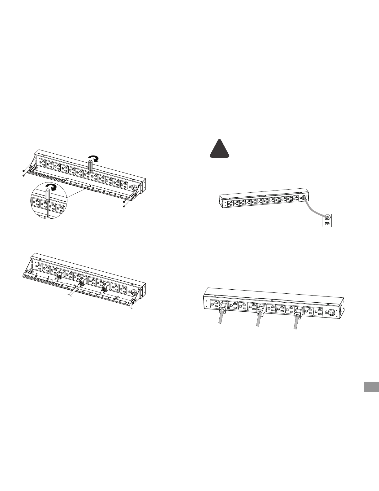
Cord Retention Tray Installation
(Optional for both horizontal and vertical installation)
Electrical Installation
1. Adjust the length of the Cord Retention Tray until the screw hole on
the Tray and PDU are aligned.
1. Receptacle evaluation: Ensure that the plug type of your PDU unit (e.g. NEMA 5-15P, NEMA
5-20P, NEMA L5-30P) matches the wall receptacle type that you are using.
PDU must be plugged into a three-wire, grounded wall receptacle only.
The wall receptacle must also be connected to an appropriate branch
circuit/main with fuse or circuit breaker protection. Connection to any
other type of wall receptacle may result in a shock hazard.
2. Attach the Cord Retention Tray to the PDU with the 4 supplied
Cord Retention Tray Mounting Screws (M3 X 6). Tighten the Cord
Retention Tray with the screw on it.
3. Use the Cable Ties provided to fasten each power cord to the Cord
Retention Tray.
!
2. Plug PDU into the wall outlet
3. Attach equipment to PDU
Before attaching equipment, it is important to calculate the total load that you
will be placing on the PDU. It is extremely important not to exceed the PDU’s
maximum current load (as outlined in the Specifications section). In order to
determine your total load, simply add up the amperage of your devices and
ensure that it does not exceed the unit’s capacity.
Page 7

PRODUCT FEATURES
PDU14B15A0U PDU14B15A1U
AC Power Cord
Circuit Breaker
External Grounding Site
Cord Retention Tray Screw Holes
Cord Retention Tray Screw Holes
Front Outlets
Front
Front Back
Circuit Breaker
Front Outlets
Cord Retention Tray Screw Holes
Cord Retention Tray Screw Holes
Circuit Breaker
External Grounding Site
Back Outlets
Page 8

PDU14B15A1U
Input
Voltage: 100 ~ 125 V
Max Current 15 A
Circuit Breaker 15 A
Plug Type: NEMA 5-15P
Cord Length: 15 FT
Output
Voltage: 100 ~ 125 V
Current: 15 A
Outlet Type: NEMA 5-15R
Dimensions (LxWxD)
17.5 x 1.7 x 2.2 inches
Humidity
Operating 0 to 95% Non-condensing
Non-Operating 0 to 95% Non-condensing
Altitude
Operating 0ft to 10,000ft
Non-Operating 0ft to 50,000ft
Temperature
Operating 32F to 95F
Non-Operating 5F to 113F
Compliance
ETL (followed UL 1363),
CSA C22.2, RoHS
Warranty
3 years
PDU14B15A0U
Input
Voltage: 100 ~ 125 V
Max Current 15 A
Circuit Breaker 15 A
Plug Type: NEMA 5-15P
Cord Length: 10 FT
Output
Voltage: 100 ~ 125 V
Current: 15 A
Outlet Type: NEMA 5-15R
Dimensions (LxWxD)
24 x 1.7 x 1.5 inches
Humidity
Operating 0 to 95% Non-condensing
Non-Operating 0 to 95% Non-condensing
Altitude
Operating 0ft to 10,000ft
Non-Operating 0ft to 50,000ft
Temperature
Operating 32F to 95F
Non-Operating 5F to 113F
Compliance
ETL (followed UL 1363),
CSA C22.2, RoHS
Warranty
3 years
TECHNICAL SPECIFICATIONS
Page 9

SAFETY + WARNINGS
1. CAUTION! Use ONLY the supplied hardware (including screws, pegs
and cord retainer clips) to attach the mounting brackets. Using
dierent hardware or improper installations may cause damage
that is NOT covered by this warranty.
2. The PDU must only be plugged into a three-wire, grounded outlet
on a circuit protected by a fuse or circuit breaker. Connection to
any other type of power outlet may result in a shock hazard.
3. Do not use extension cords or adapters with this PDU.
4. Never install a PDU, or associated wiring or equipment, during a
lightning storm.
5. Check that the power cord, plug, and socket are in good condition.
6. CAUTION! To prevent the risk of re or electric shock, this PDU
should be installed in a temperature and humidity controlled
indoor area free of conductive contaminants. Do not install this
PDU where excessive moisture or heat is present.
Read the following before installing or operating the Power
Distribution Unit (PDU)
Safety Precautions Trouble Shooting
Problem Possible Cause Solution
PDU Outlets do not
provide power to
connected
equipment
Open breaker,
Loose power cord
Reset Breaker. Check if
plug is completely
connected.
If the problem remains
contact tech support.
Circuit breaker has
tripped
Sustained overload,
Excessive ambient or
internal temperatures,
Faulty breaker
Reset Breaker.
If the problem remains,
contact tech support.
Page 10

English: 3 Year Limited Warrant y
V7 Limited Manufacturer’s Warranty covers this Product against defects in materials or workmanship from the date of purchase for a period of 36 months for parts and labor. Liability
under this limited warranty shall in no event exceed the cost of replacement or the original cost of the product at the time of purchase. In the event of product discontinuance or
unavailability wherein failure has occurred the product shall, at the sole discretion of Manufacturer, be replaced to the first purchaser with a substantially similar product of equal or
lesser value or the first purchaser shall be provided with a refund equal to the original i.e. first purchaser purchase price. This limited warranty does not cover the repair of cracked,
scratched, broken or modified plastic or other cosmetic damage; or parts that have been altered, defaced or removed. Also, it does not apply to repairs or replacement necessitated
by any cause beyond the control of the Manufacturer or a servant or agent of the Manufacturer including, but not limited to, any malfunction, defects or failures which in the
opinion of Manufacturer were caused by or resulting from unauthorized service or parts, improper maintenance, operation contrary to furnished instructions, shipping or transit
accidents, modification or repair by the user, abuse, misuse, neglect, accident, fire, flood, or other acts of God, incorrect line voltage or normal wear and tear, or which did not exist
at the time when the Product was purchased. This limited warranty does not apply to damage that occurs during unpacking, setup, or installation; removal of the product for repair;
reinstallation of the product after repair, or shipping cost of the product for any purpose. There are no other expressed warranties, whether written or oral, other than this printed
limited warranty. All implied warranties, including without limitation the implied warranties or merchantability or fitness for a particular purpose, are limited to the durations of this
limited warranty. In no event shall V7 be liable for incidental or consequential damages of any nature whatsoever, including but not limited to lost profit or commercial loss, to the
full extent those damages can be disclaimed by law. Some countries do not allow the exclusion or limitation of liability arising from implied warranties, or limitation of the duration
of implied warranties, so the preceding limitations or exclusions may not apply to all purchasers. This limited warranty is subject to the laws of the relevant jurisdiction, being the
country where the product is originally purchased. This limited warranty shall only apply to the extent permitted by applicable national legislation governing the sale of consumer
goods. The rights and remedies that consumers enjoy under such consumer protection laws shall not be limited. This warranty is valid only in the country where the product is
originally purchased. Additional information can be found at www.V7-world.com.
You may execute this warranty where you purchased in accordance with the exchange policy of the establishment. At any time thereafter during the term of this warranty, please
refer to the authorized distributor of your jurisdiction.
Français : Garantie limitée de 3 ans
La garantie limitée du fabricant V7 couvre ce produit contre les défauts de matériaux ou de fabrication pour une période de 36 mois à compter de la date d’achat pour les pièces et
la main-d’œuvre. L’obligation, dans le cadre de cette garantie limitée, n’excédera en aucun cas le coût de remplacement ou le coût d’origine du produit au moment de son achat. En
cas de discontinuité ou d’indisponibilité du produit au moment où la panne s’est produite, le produit sera, à la seule discrétion du fabricant, remplacé au profit du premier acheteur
par un produit substantiellement semblable d’une valeur égale ou inférieure, ou le premier acheteur recevra un remboursement égal au prix original c’est-à-dire au prix d’achat
par le premier acheteur. Cette garantie limitée ne couvre pas la réparation du plastique craquelé, rayé, brisé ou modifié, ou tout autre dommage esthétique, ni les pièces ayant été
modifiées, dégradées ou démontées. En outre, elle ne s’applique pas aux réparations ou au remplacement nécessaires après un événement, quel qu’il soit, hors du contrôle du
fabricant, ou d’un employé ou d’un agent du fabricant, notamment les dysfonctionnements, défauts ou défaillances qui, selon le fabricant, ont été provoqués ou résultent d’un
entretien ou de pièces non autorisés, d’une maintenance inadéquate, d’une utilisation contraire aux instructions fournies, d’accidents d’expédition ou de transport, de modifications
ou de réparations par l’utilisateur, d’abus, de mésusage, de négligence, d’un accident, d’un incendie, d’une inondation ou d’un autre cas de force majeure, d’une tension secteur
incorrecte ou de l’usure normale, ou qui n’existaient pas au moment de l’achat du produit. Cette garantie limitée ne s’applique pas aux dommages produits lors du déballage, de la
mise en place ou de l’installation, de la dépose du produit pour réparation, de la réinstallation du produit après réparation, ni aux frais d’expédition de l’article pour quelque raison
que ce soit. Il n’existe aucune autre garantie, explicite, écrite ou orale, que cette garantie limitée imprimée Toutes les garanties implicites, notamment les garanties implicites ou de
qualité marchande ou d’adaptation à un but particulier, sont limitées à la durée de cette garantie limitée. En aucun cas, V7 ne sera responsable des dommages fortuits ou indirects,
quelle que soit leur nature, notamment, des pertes de bénéfices ou des pertes commerciales, dans la mesure où ces dommages peuvent être rejetés par la loi. Certains pays n’acceptent pas l’exclusion ou la limitation de responsabilité découlant de garanties implicites ou les limites de durée des garanties implicites, c’est pourquoi les exclusions ou limitations
précédentes peuvent ne pas s’appliquer à tous les acheteurs. Cette garantie limitée est assujettie aux réglementations locales en vigueur, c’est-à-dire celles du pays dans lequel le
produit à été originellement acheté. Cette garantie limitée ne s’appliquera que conformément à la législation nationale en vigueur régissant la vente de biens de consommation. Les
droits et les recours dont peuvent bénéficier les consommateurs tels que les lois les protégeant ne seront pas limités. Cette garantie n’est valable que dans le pays où le produit à été
originellement acheté. Pour des informations complémentaires, reportez-vous à www.V7-world.com.
3 Year Warranty
USA
Ingram Micro Inc.
3351 Michelson Dr. Suite 100
Irvine, CA 92612, USA
Canada\
Ingram Micro, LP Canada
55 Standish Court
Mississauga, ON, L5R 4A1, Canada
www.V7-world.com
Model/ Modèle :
Date of purchase/ Date d’achat:
Page 11

TABLE DES MATIÈRES
1 Démarrage
Contenu du paquet
2 Installation
Montage du rack en position horizontal (Modèle 1U
uniquement)
Montage du rack en position verticale (Modèles 0U
et 1U)
Supports à encoches (Modèle 0U uniquement)
Plaque 6” pour montage du rack en position verticale
(Modèle 0U uniquement)
Installation du panneau passe-câbles
Installation électrique
3 Caractéristiques du produit
4 Spécications techniques
Basic Series (1U)
Basic Series (0U)
5 Sécurité et avertissements
Page 12

DÉMARRAGE
Contenu du paquet
Accessoires inclus
PDU14B15A0U PDU14B15A1U
Panneau passe-câbles
Supports de montage
rack pour installation
horizontale
Vis de montage pour support
M4x6 (4unités)
Vis de montage pour
panneau passe-câbles
M3x6 (4unités)
Taquets de montage à
encoches (2unités) avec vis
M4x6 (2unités)
(modèles 0U uniquement)
Attaches pour câbles
(pour panneaux passe-câbles)
Vis de mise à la terre
M4x6 (1unité)
Plaque 6" pour montage du rack en
position verticale
(Modèles 0U uniquement)
ArrièreAvant
Supports de
montage rack pour
installation verticale
Page 13

INSTALLATION
Montage de rack en position horizontale
(modèles 1U uniquement)
Montage du rack en position verticale (0U et 1U)
1. Fixez les supports de montage horizontaux sur la PDU.
1. Fixez les supports de montage verticaux sur le PDU.
2. Placez le PDU en position horizontale sur le rack.
2. Fixez le PDU en position verticale sur le rack.
Placez les vis de montage pour
support (M4x6) dans des trous
de xation en diagonale les uns
par rapport aux autres.
Placez les vis de montage pour
support (M4x6) dans des trous
de xation en diagonale les uns
par rapport aux autres.
Installez le PDU à l’aide
de xations compatibles
avec le rack.
Installez le PDU à l’aide de xations
compatibles avec le rack.
Page 14

Plaque 6" pour montage du rack en position verticale
(Modèles 0U uniquement)
Montage du rack avec des encoches (modèles 0U uniquement)
1. Installation des encoches de montage 1. Fixez la plaque 6” sur le PDU.
2. Fixez-les sur le rack. 2. Fixez-la sur le rack.
Fixez les taquets de montage à encoches
sur la PDU à l’aide des 2vis de montage
pour support (M4x6) fournies.
Alignez les supports de montage à encoches
sur les fentes d’encoches du rack.
Insérez et faites glisser vers le bas an qu’ils
soient fermement verrouillés.
Installez le PDU à l’aide de xations
compatibles avec le rack.
Page 15
Installation du panneau passe-câbles
(optionnel, pour installations verticales comme horizontales)
Installation électrique
1. Ajustez la longueur du panneau passe-câbles jusqu’à ce que les
trous de xation du panneau et de le PDU soient alignés.
1. Évaluation de la prise de courant: Assurez-vous que le type de prise de votre unité PDU
(par ex., NEMA5-15P, NEMA5-20P, NEMAL5-30P) correspond au type de prise murale que
vous utilisez.
Le PDU doit être branchée uniquement sur une prise murale avec mise à la terre.
La prise murale doit également être connectée à un circuit de dérivation/principal
adapté et protégé par un fusible ou un disjoncteur. L’utilisation de tout autre type
de prise murale peut présenter un risque d’électrocution.
2. Fixez le panneau passe-câblesau PDU à l’aide des 4vis de montage
pour panneau passe-câbles (M3x6) fournies. Serrez correctement
le panneau passe-câbles après avoir apposé les vis.
3. Attachez chaque cordon d’alimentation au panneau passe-câbles
à l’aide des attaches pour câbles fournies.
!
2. Branchez le PDU sur la prise murale.
3. Raccordez le matérielau PDU.
Avant de raccorder le matériel, il est important de calculer la charge totale que vous allez
placer sur le PDU. Il est extrêmement important de ne pas dépasser la charge maximale
de courant électrique du PDU (comme indiqué dans la section Spécifications). Pour
déterminer la charge totale de votre matériel, il vous suffit d’additionner l’intensité du
courant électrique de chacun de vos appareils en vous assurant que leur somme ne
dépasse pas la capacité maximale de la PDU.
Page 16

CARACTÉRISTIQUES DU PRODUIT
PDU14B15A0U PDU14B15A1U
Cordon d’alimentation
Disjoncteur
Sortie à la terre
Trous de xation du panneau passe-câbles
Trous de xation du panneau passe-câbles
Prises avant
Avant
Avant Arrière
Disjoncteur
Prises avant
Trous de xation du panneau
passe-câbles
Trous de xation du panneau
passe-câbles
Disjoncteur
Sortie à la terre
Prises arrière
Page 17

PDU14B15A1U
Alimentation
Tension : 100 ~ 125 V
Tension maximale : 15 A
Disjoncteur : 15 A
Type de prise : NEMA 5-15P
Longueur du cordon : 3 m
Sortie
Tension : 100 ~ 125 V
Courant : 15 A
Type de sortie : NEMA 5-15R
Dimensions
(Longueurx Largeurx
Profondeur)
17,5 x 1,7 x 2,2 pouces
Humidité
En fonctionnement : 0 à 95 % sans
condensation
Hors fonctionnement : 0 à 95 % sans
condensation
Altitude
En fonctionnement : 0 à 3 000 m
Hors fonctionnement : 0 à 15 000 m
Température
En fonctionnement : 0 à 35 °C
Hors fonctionnement : -15 à 45 °C
Conformité
ETL (conforme à la norme UL 1363),
CSA C22.2, RoHS
Garantie
3 ans
PDU14B15A0U
Alimentation
Tension : 100 ~ 125 V
Tension maximale : 15 A
Disjoncteur : 15 A
Type de prise : NEMA 5-15P
Longueur du cordon : 3 m
Sortie
Tension : 100 ~ 125 V
Courant : 15 A
Type de sortie : NEMA 5-15R
Dimensions
(Longueurx Largeurx
Profondeur)
24 x 1,7 x 1,5 pouces
Humidité
En fonctionnement : 0 à 95 % sans
condensation
Hors fonctionnement : 0 à 95 % sans
condensation
Altitude
En fonctionnement : 0 à 3 000 m
Hors fonctionnement : 0 à 15 000 m
Température
En fonctionnement : 0 à 35 °C
Hors fonctionnement : -15 à 45 °C
Conformité
ETL (conforme à la norme UL 1363),
CSA C22.2, RoHS
Garantie
3 ans
SPÉCIFICATIONS TECHNIQUES
Page 18

SÉCURITÉ ET AVERTISSEMENTS
1. AVERTISSEMENT! Utilisez UNIQUEMENT le matériel fourni (vis,
taquets et attaches pour câble) pour xer les supports de montage.
L’utilisation de tout autre matériel ou installation non conforme
peut entraîner des dommages qui ne sont PAS couverts dans le
cadre de cette garantie.
2. Le PDU doit être branchée uniquement sur une prise électrique
avec mise à la terre, sur un circuit protégé par un fusible ou un
disjoncteur. L’utilisation de tout autre type de prise électrique peut
présenter un risque d’électrocution.
3. N’utilisez pas de rallonge électrique ou d’adaptateur avec cette PDU.
4. N’installez jamais un PDU, ainsi que tout câblage ou matériel
associé, pendant un orage.
5. Vériez que le câble d’alimentation, la prise électrique et la che
sont en bonne état.
6. AVERTISSEMENT! Pour éviter tout risque d’incendie ou
d’électrocution, ce PDU doit être installée dans un espace intérieur
contrôlé (température et humidité contrôlées, sans polluant
conducteur). N’installez pas ce PDU dans un environnement oùil
pourrait être exposée à une chaleur ou une humidité excessive.
Veuillez lire les consignes suivantes avant d’installer ou de mettre en
route l’unité (PDU).
Mesures de sécurité Résolution des problèmes
Problème Cause probable Solution
Les prises du PDU
ne fournissent pas
d'alimentation
pour connecter des
équipements
Le disjoncteur est
ouvert ;
le cordon d’alimentation
n’est pas correctement
branché
Réarmez le disjoncteur. Vérifiez
que la prise est correctement
connectée.
Si le problème persiste, veuillez
contacter le service d’assistance
technique.
Le disjoncteur s’est
déclenché
Surcharge prolongée ;
températures ambiante
ou interne trop élevées ;
disjoncteur défectueux
Réarmez le disjoncteur.
Si le problème persiste, veuillez
contacter le service d’assistance
technique.
Page 19

www.V7-world.com
Garantie limitée de 3 ans
Vous pouvez faire valoir cette garantie auprès du revendeur chez lequel vous avez acheté le produit, conformément à la politique d’échange de l’établissement en question. Veuillez
vous reporter aux distributeurs autorisés de votre région, à tout moment et pendant toute la période de validité de cette garantie.
Français : Garantie limitée de 3 ans
V7 propose une garantie couvrant ce produit contre les défauts de matériaux ou de fabrication. Celle-ci est valable pendant une période de 36 mois à compter de la date d’achat,
tant pour les pièces que pour la main-d’œuvre. L’obligation, en vertu de cette garantie limitée, n’excédera en aucun cas le coût de remplacement ou le coût d’origine du produit
au moment de son achat. En cas de discontinuité ou d’indisponibilité du produit au moment de la panne, celui-ci sera, à la seule discrétion du fabricant, remplacé, au profit du
premier acheteur, par un produit substantiellement similaire, d’une valeur égale ou inférieure, ou le premier acheteur recevra un remboursement équivalant au prix initial, à savoir le
prix d’achat par le premier acheteur. Cette garantie limitée ne couvre pas la réparation du plastique craquelé, rayé, brisé ou modifié, ou tout autre dommage esthétique. Les pièces
modifiées, dégradées ou démontées ne sont pas couvertes par la garantie. Par ailleurs, il convient de noter que la garantie ne s’applique pas aux réparations ou remplacements
nécessaires après un quelconque événement hors du contrôle du fabricant, d’un employé ou d’un agent du fabricant, notamment les dysfonctionnements, défauts ou défaillances
qui, selon le fabricant, résultent d’un entretien ou de l’installation de pièces non autorisés, d’une maintenance inadéquate, d’une utilisation contraire aux instructions fournies,
d’accidents d’expédition ou de transport, de modifications ou de réparations effectuées par l’utilisateur, d’abus, de mésusage, de négligence, d’un accident, d’un incendie, d’une
inondation ou d’un autre cas de force majeure, d’une tension secteur inadéquate ou de l’usure normale, ou tout dysfonctionnement, défaut ou défaillance qui n’existait pas au
moment de l’achat du produit. Cette garantie limitée ne couvre pas les dommages occasionnés lors du déballage, de la mise en place ou de l’installation, de la dépose du produit
pour réparation, de la réinstallation du produit après réparation, ni les frais d’expédition du produit pour quelque raison que ce soit. Il n’existe aucune autre garantie, explicite, écrite
ou orale, que la présente garantie limitée imprimée. Toutes les garanties implicites, notamment les garanties implicites ou de qualité marchande ou d’adaptation à un but particulier,
sont limitées à la durée de la présente garantie limitée. V7 ne sera en aucun cas responsable des dommages fortuits ou indirects, quelle que soit leur nature, tels que des pertes de
bénéfices ou des pertes commerciales, dans la mesure où ces dommages peuvent être rejetés par la loi. Il arrive que des pays refusent l’exclusion ou la limitation de responsabilité
découlant de garanties implicites ou les limites de durée des garanties implicites. Il se peut dès lors que les exclusions ou limitations précédentes ne soient pas applicables à tous les
acheteurs. La présente garantie limitée est valable en vertu des réglementations locales en vigueur, à savoir celles du pays dans lequel le produit a été délivré. Cette garantie limitée ne
s’appliquera que conformément à la législation nationale en vigueur régissant la vente de biens de consommation. Les droits et recours dont peuvent bénéficier les consommateurs,
tels que les lois les protégeant, ne seront en aucun cas limités. Cette garantie est valable uniquement dans le pays où le produit a été délivré. Pour en savoir plus, rendez-vous sur
www.V7-world.com.
Siège Social
INGRAM MICRO
208 Allée de Iinnovation
CS 30221
59812 LESQUIN CEDEX
R.C.S Lille Métropole 344658 117
Contact commerical: 0825 825825 *
Contact administratif: 0826 464 726 *
Modèle :
Date d’achat :
Centre Logistique
INGRAM MICRO
Avenue de la Rotonde
59160 Lomme
Agences Île-de-France
INGRAM MICRO
25 rue Mickael Faraday
78180 Montigny le
Bretonneux
INGRAM MICRO
2-4 boulevard des lles
92130 lssy les Moulineaux
Page 20

www.V7-world.com
V2-20170629
 Loading...