

Page 1
!
!
!
!
!
!
!
!
!
!
!
!
!
!
!
!
!
!
!
!
!
!
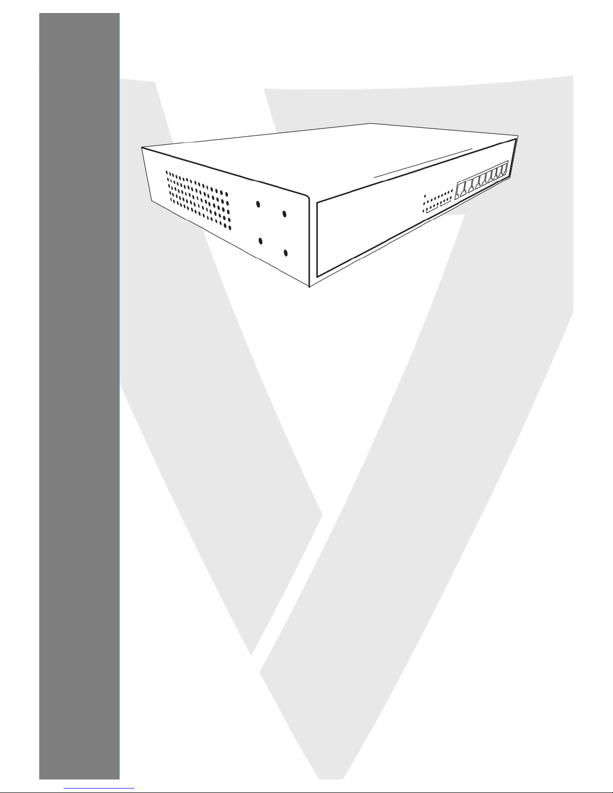
USER MANUAL
Managed Switch
MPEGS24
Page 2

Chapter!1!Product!Introduction! ! ! ! ! ! ! ! ! ! ! ! ! ! ! ! ! ! ! ! !
!
1.2!Features!
l Supports!24!10/100/1000Mbps!Gigabit!Ethernet!ports!and!4!mini-GBIC/SFP!slots!
l IEEE!802.3af/at!PoE!compliant!to!simplify!deploymen t!an d!ins tallatio n!
l Supports!PoE!up!to!30!W!per!port!with!400!W!total!power!budget!
l Automatically!detects!powered!devices!(PD)!and!power!consumption!levels!
l IEEE!802.1Q!VLAN!allo w s !n et w o rk !se g mentation!to!enhance!perfo rmance!and!security!
l Supports!Access!Control!List!(ACL)!
l Switch!capacity:!56Gbps,!Forwarding!rate:!35.7Mbps!
l Supports!IGMP!Snooping!V1 !/!V 2!
l 8K!MAC!address!table!and!9K!jumbo!frames!
l 19-inch!rack-mountable!metal!case!
!
1.3!External!Component!Description!
1.3.1!Front!Panel! !
The!front!panel!of!the!switch!consists!of!24!x!10/100/1000Mbps!RJ-45!ports,!4!x!SFP!ports!and!a!series!of!LED!
indicators!as!shown!as!be lo w :! !
!
!
! Front!Panel!
10/100/1000Mbps!RJ-45!ports!(1~24):!
Connect!to!network!devices!with!a!bandwidth!of!10Mbps,!100Mbps!or!1000Mbps.!
!
SFP!ports!(SFP1,!SFP2,!SFP3,!SFP4):!
Designed!to!install!SFP!modules!and!connect!to!network!devices!with!a!bandwidth!of!1000Mbps.! !
!
! LED!Indicators!
The!following!chart!shows!the!LED!indicators!of!the!Switch!along!with!explanation!of!each!indicator.!
Power:!Green! !
− Off:!Power!off!
− On:!Power!on!
!
Page 3
MANAGED SWITCH
System:!Green!
− Off:!System!not!ready!
− On:!System!ready!
− Blinking:!System!booting!
!
Copper!Port!1G:!Green!
− Off:!No!1G!link!
− On:!1G!link!
!
Copper!Port:!Yellow!
− Off:!100M!link!fail!
− Flashing:!Sending!or!receiving!data!
!
SFP:!Green!
− Off:!Link!fail!
− On:!Connected!
!
SFP:!Yellow!LED!
− Off:!Not!sending!or!receiving!data!
− Flashing:!Sending!or!receiving!data!
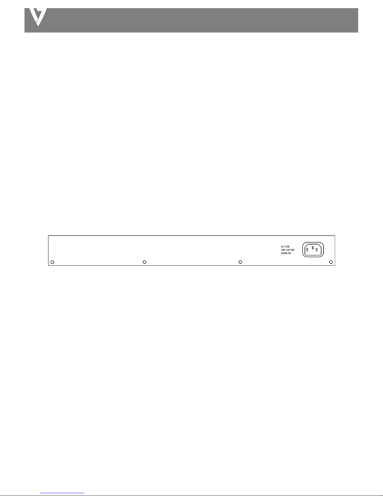
1.3.2!Rear!Panel!
The!rear!panel!of!the!switch!features!the!AC!power!connecto r:!
!
! Rear!Panel
!
AC!Power!Connector:! !
Power!is!supplied!through!an!external!AC!power!adapter.!Supports!AC!100!–!240V,!50-60Hz
!
! !
1.4!Package!Contents!
l MPEGS!Switch! !
l Quick!Installation!Guide!
l Power!Cord!
l Rack-Mount!Kit!
!
!
!
!
!
!
!
Page 4
MANAGED SWITCH
Chapter!2!Installing!and!Connecting!the!Switch! ! ! ! !!!!!
2.1!Installation! !
Ø Put!the!switch!in!a!stable!place!such!as!a!desktop!to!avoid!falling.! !
Ø Ensure!the!switch!works!in!the!proper!AC!input!range!and!matches!the!voltage!labeled.! !
Ø Do!not!open!the!switch’s!outer!case!even!in!the!event!of!power!failure.! !
Ø Ensure!there!is!proper!heat!dissipation!from!and!adequate!ventilation!around!the!switch.! !
Ø Ensure!the!switch’s!location!can!support!the!weight!of!the!switch!and!its!accessories.! !
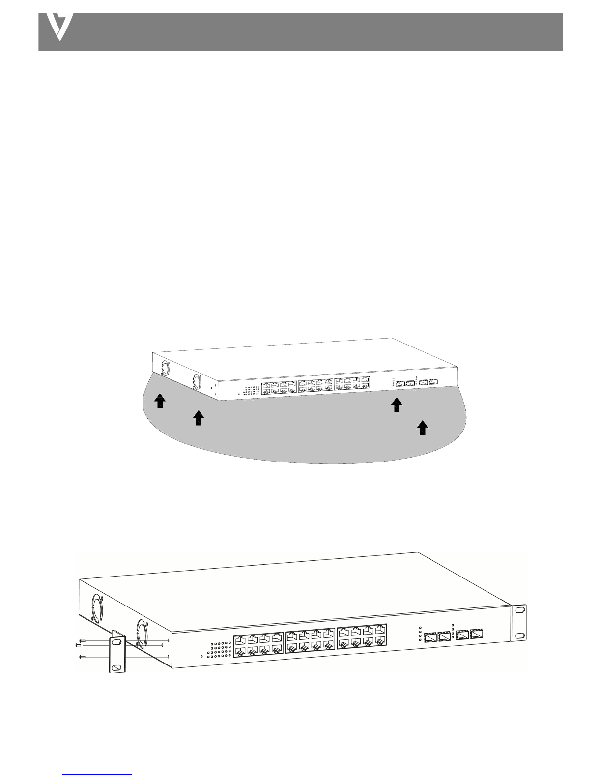
2.1.1!Desktop!Installation! !
Attach!the!cushioning!rubber!feet!provided!on!the!bottom!corners!of!the!switch!to!protect!against!external!
vibration.!Allow!adequate!space!for!ventilation!between!the!device!and!any!objects!around.!i
!
Figure!4!-!Desktop!Installation!
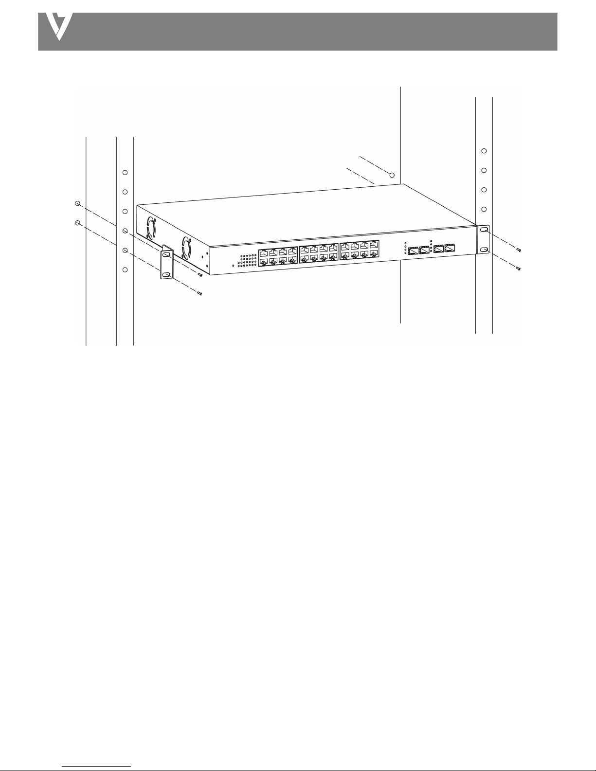
2.1.2!Rack-mountable!Installation!in!19-inch!Cabinet! !
!
!
Bracket!Installation!
!
A. Use!the!screws!provided!with!the!equipment!rack!to!mount!the!Switch!on!the!rack!and!tighten!it.! !
Page 5
MANAGED SWITCH
!
!
Rack!Installation!
2.1.3!Power!on!the!Switch! !
The!Switch!is!powered!on!by!the!AC!100-240!V!50/60Hz!internal!high-performance!power!supply.!
!
AC!Electrical!Outlet:!
It!is! recommended! to! use! a! single-phase! three-wire!receptacle! with! neutral!outlet! or! multifunctional! compute r!
professional!receptacle.!Please!make!sure!to!connect!the!metal!ground!connector!to! the! grounding!source! on! the!
outlet.!
!
AC!Power!Cord!Connection:! !
Connect!the!AC!power!connector!on!the!back!panel!of!the!switch! to! external!receptacle!with!the!included!power!
cord,!and!check!the!power!LED!is!on.!
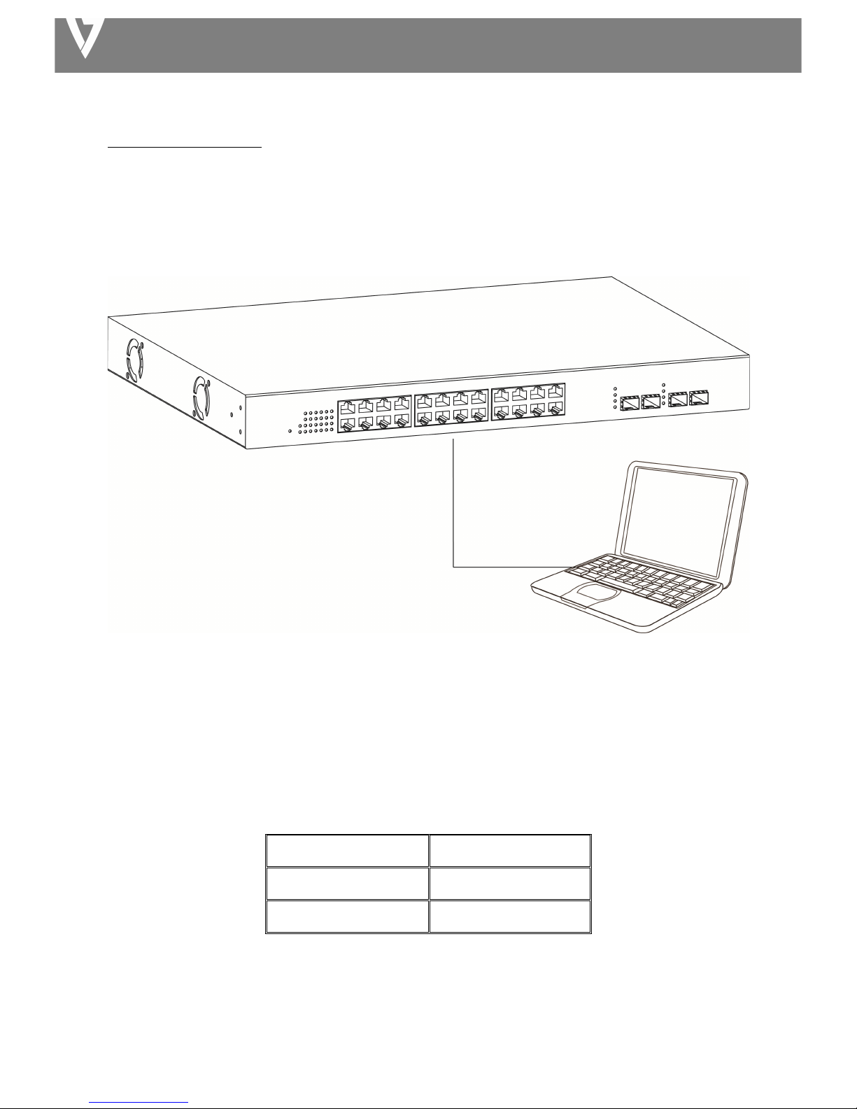
2.2!Connect!Computer!(NIC)!to!the!Switch!
Please!insert!the!NIC!into!the!computer,!and!after!installing!network!card!driver!conn ect!one!end!of!the!RJ-45!
cable!to!your!computer!and!the!other!end!to!any!RJ-45!port!of!the!switch,!with!a!maximum!distance!between!
switch!and!computer!around!100!meters.!After!the!devices!are!powered!on!the!LINK/ACT/Speed!status!indicator!
lights!will!display!for!corresponding!ports!of!the!switch.!
Page 6

MANAGED SWITCH
2.3!Switch!connection!to!the!PD!(Powered!Device)!
Ports!1-24!provide!PoE!power!supply!functionality!with!a!maximum!output!power!up!to!30W!each!port.!This!can!
power!PD!devices!such!as!internet!phones,!network!cameras,!w ire le s s!a c ce s s !p o in t s!etc.!Connect!the!switch!PoE!
port!directly!connected!to!the!PD!port!using!a!network!cable.!
Page 7
MANAGED SWITCH
Chapter!3!Login!!!
3.1!Switch!to!PC!
Use!a!standard!Cat!5/5e!Ethernet!cable!(UTP/STP)!to!connect!the!switch!to!OS!System.!
!
!
PC!Connect!
3.2!Login!
Open!a!web! browser! and!go!to!the!switch’s!IP!ad dre ss.!The! de fau lt!IP!add ress!is!192.168.1.1.!Your!computer’s!IP!
address!m ust! be! in!the!same!subnet! as! the! switch.!For!the!default!IP! address! this!is!any! IP! address! in!the!range!
192.168.1.x!(x!=!2!–!254).!You!can!modify!the!IP!address!of!your!computer!if!you!need.!
!
!
!
!
!
1. Enter!the!switch’s!IP!address!(192.168.1.1)!in!the!URL!bar!of!a!web!browser.!IE!7!or!above!is!
recommended.!
Default!IP!address! !
192.168.1.1! !
Default!user!name! !
admin!
Default!password! !
admin!
Page 8
MANAGED SWITCH
!
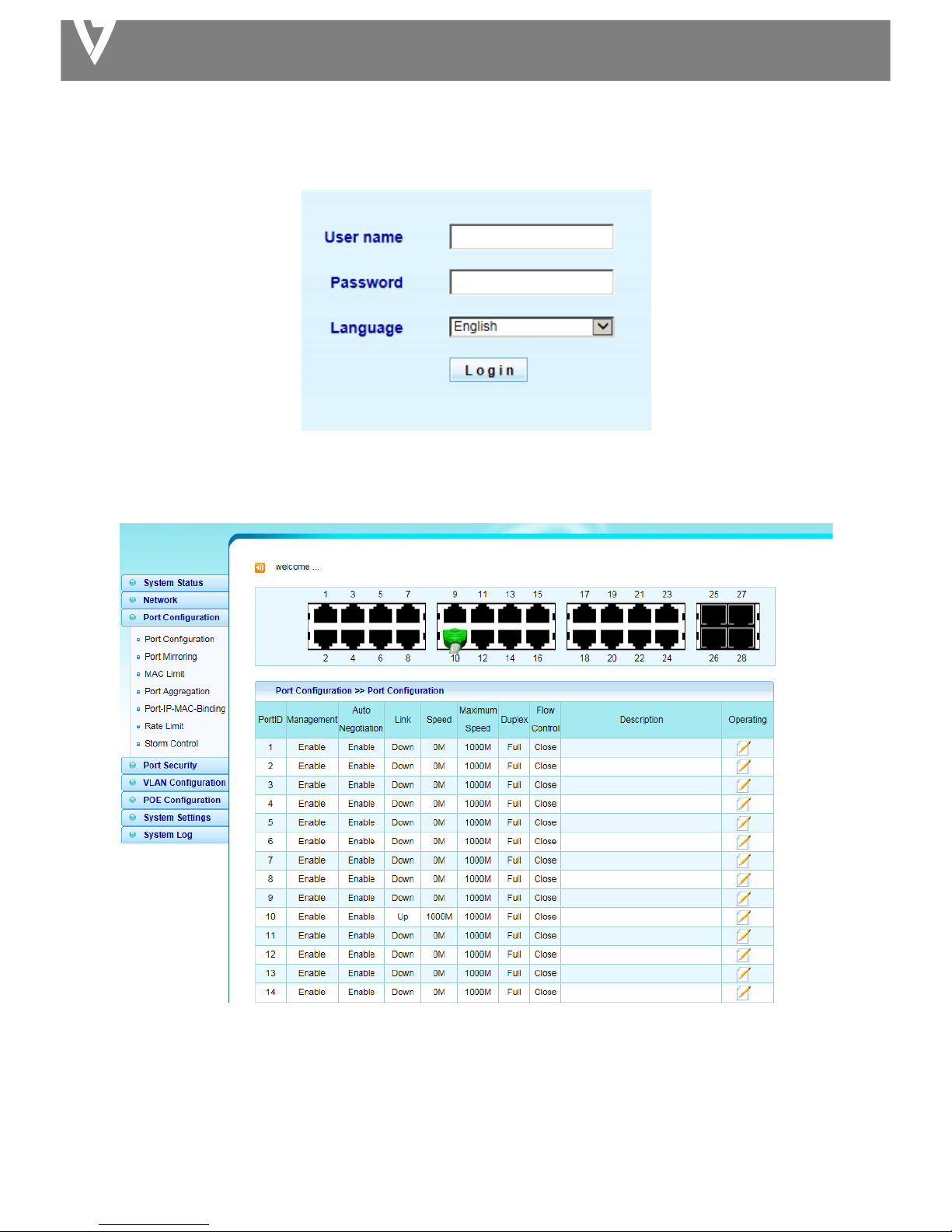
2. At!the!following!screen!login!with!the!default!username!“admin”!and!password!“ad,om”.!
!
3. You!will!arrive!at!the!switch!configuration!window!as!shown!below:!
!
!
Page 9
MANAGED SWITCH
Chapter!4!Switch!Configuration! ! ! ! ! ! ! ! ! ! ! ! ! ! ! ! ! ! !
4.1!System!Status! !
View!device!information!and!stat us .!
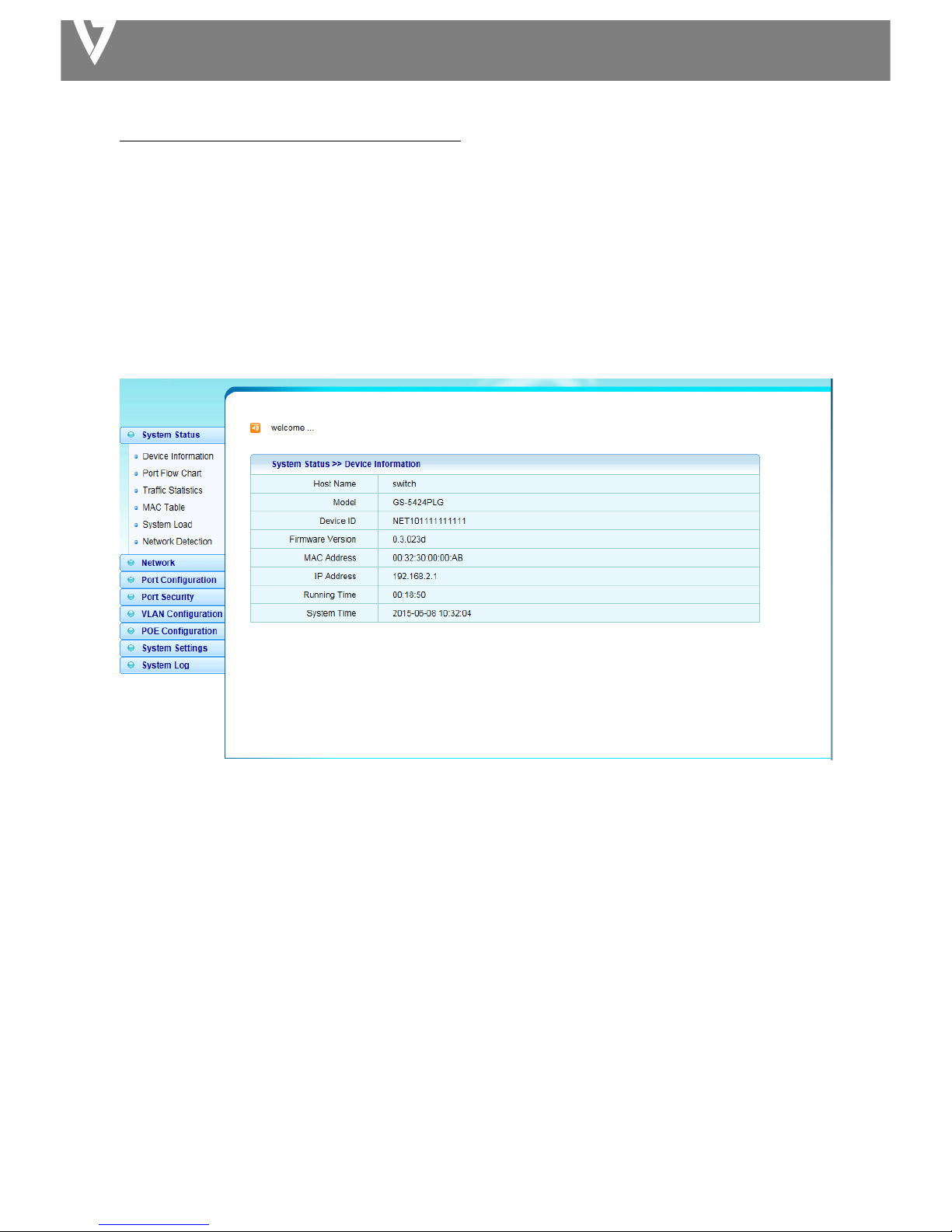
4.1.1!Device!Information!
This!page! allow!you!to!configure!status!related! in formation! an d ! view! status! information ! such! as! Device!ID,!MAC!
address,!IP!Address!and!System!Time.!
!
!
Host!Name:!System!name!of!the!switch.!This!name!will!also!be!used!as!CLI!prefix.!
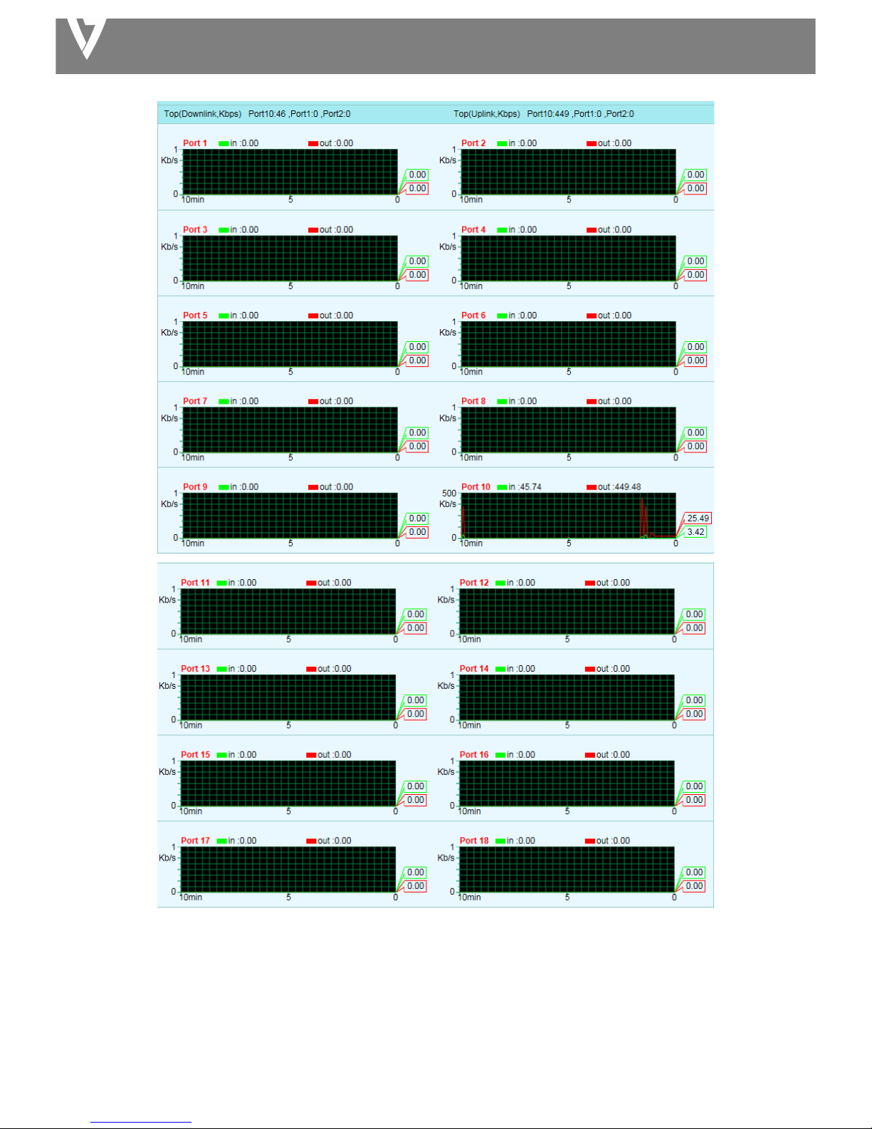
4.1.2!Port!Flow!Chart!
System!Status!>!Port!Flow!Chart!
Port!Select:!Select!one!or!multiple!ports!to!configure.!
Enabled:!Port!admin!state.! !
l Enabled:!Enable!the!port.! !
l Disabled:!Disable!the!port.! !
!
Page 10
MANAGED SWITCH
!
!
Page 11
MANAGED SWITCH
!
!
!
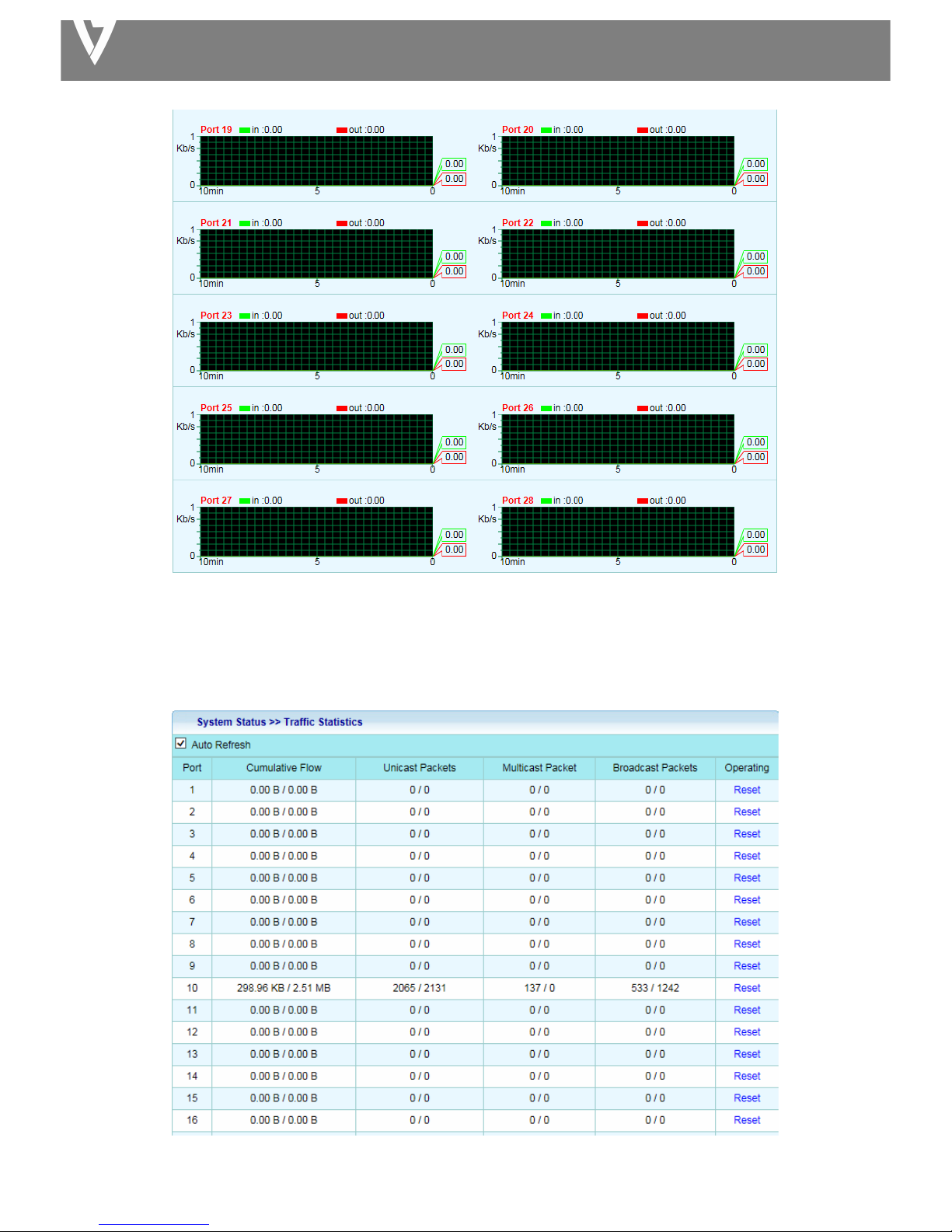
4.1.3!Traffic!Statistics!
!
Page 12

MANAGED SWITCH
!
!
4.1.4!Mac!Table!
4.1.4.1!Forwarding!List!
!
4.1.4.2!Set!Static!MAC!
Mac!Table!>!Set!Static!MAC!
!
MAC!Address:!The!MAC!address!to!which!packets!will!be!statically!forwarded.!If!Type!is!uncast,!enter!uncast!MAC!
address!in!this!field;!If!Type!is!multicast,!enter!multicast!M A C !ad d re s s!in !t h is!fie ld .! !
Port:! If! Type ! is!uncast,! select! the! port! number!of!the! MAC! entry;! If! Type! is!multicast,!select!the! port! list! of! th e!
MAC!entry.!
VLAN:!The!VLAN!ID!number!of!the!VLAN!on!which!the!above!MAC!address!resides.! !
!
4.1.4.3!Dynamic!Address!Settings!
Mac!Table!>!Dynamic!Address!Settings!
Page 13

MANAGED SWITCH
!
4.1.5!System!Load!
!
!
Service:! ! Enable:!Select!CPU!Threshold!percent!&!Memory!Threshold!percent.!!!!!!!!!!!!!!!
!!!!!!!!! Disable:!CPU!Threshold!&!Memory!Threshold!disabled.!
!
!!!!!!!!
4.1.6!Network!detection!
!
!
4.2!Network!
4.2.1!IP!Address! !
Network!>!IP!Address!
This!page!allows!you!to!edit!IP!address,!Net!Mask!and!Gateway.!
Page 14

MANAGED SWITCH
!
IP!Address:!If!static!mode !is !en a b le d ,!e n te r!IP !ad d re s s!in !t h is!fie ld .! !
Net!Mask:!If!static!mode!is!enabled,!enter!subn et !mask!in!this!field.! !
4.2.2!MAC!Addresses!
Network!>!MAC!Address!
!
MAC!Address:!Select!the!MAC!address!to!show!or!clear!dynamic!MAC!entries.!If!no!port,!VLAN!and!MAC!address!
is!selected,!the!dynamic !MAC!table!will!be!cleared .! !
!
4.2.3!DNS!Settings!
Network!>!MAC!Address!
!
!
4.2.4!DHCP!Protect!
When!the!switch!uses!DHCP!Protect,!it!will!snoop!protect!message!and!DHCP!requests!and!record!the!IP!address!
and!MAC!address!from!DHCP!ACK!messages.!DHCP!Protect!allows!physical!ports!to!be!set!as!creditable!ports!or!
discreditable!ports.!Creditable!ports!can!receive!and!forward!the!DHCP!offer!message!while!discreditable!port!will!
lose!the!DHCP!offer!message .!The!switch!can!identify!false!DHCP!servers!and!ensure!that!the!client!gets!a!legal!IP!
Page 15

MANAGED SWITCH
address!from!DHCP!Server.!
!
!
4.2.5!IGMP!Snooping!
Network!>!IGMP!Snooping!
!
!
Page 16

MANAGED SWITCH
4.3!Port!Configuration!
4.3.1!Port!Configuration!
!
Page 17

MANAGED SWITCH
4.3.2!Port!Mirroring!
Port!mirroring!is!mirroring!the!TX/RX!data!flow!from!the!source!port!to!the!destination!port.!
!
!
4.3.3!MAC!Limit!
!
Page 18

MANAGED SWITCH
!
4.3.4!Port!Aggregation!
Aggregate! multiple! Ethernet! ports! together! to! form! a! logical! port,! supports! static! allocation! or! LACP.!
!
Page 19

MANAGED SWITCH
4.3.4.!ACL!
ACL!>!Bounding!List!
This!page!allows!you!to!set!port!bounding!ACL!rules.!
! !
!
!
Page 20

MANAGED SWITCH
4.3.5!Port!Limit!
Ingress!&!Egress!Port!Settings!
Rate!Limit!>!Ingress!&!Egress!Port!Settings!
This!page!allows!you!to!set!ingress!port!monitoring.!
!
!
Page 21

MANAGED SWITCH
4.3.6!Storm!Control!
Port!Configuration!>!Storm!Control! !
!
Port:!Select!ports.! !
Type!Enable:!Select!the!type!of!storm!control.! !
l Broadcast:!Broadcast!packet.! !
l Unknown!Multicast:!Unknown!multicast!packet!State.! !
l Unknown!Uncast:!Unknown!uncast!packet.!
Rate:! Value! of!storm! control! rate.! Unit:! PPS! (packet! per-second)! or! Kbps!(Kbits! per-second)! depends! on! global!
mode!setting.!The!range!is!from!0!to!1000000.! !
!
Page 22

MANAGED SWITCH
4.4!Port!Security!
4.4.1!Port!Grouping!
Security>!Port!Grouping!
Port!security!can!set!port!isolation!and!specific!behavior.!
!
!
4.5!VLAN!Configuration!
4.5.1!802.1Q!VLAN!
VLAN!Configuration!>!VLAN!List! !
!
!
Page 23

MANAGED SWITCH
4.5.2!PVID!
VLAN!ID!for!the!selected!ports:!
!
!
!
Page 24

MANAGED SWITCH
4.6.POE!Configuration! !
4.6.1.!PoE!Global!Setting!
PoE!Configuration!>!PoE!Global!Setting!
!
!
Max!Available!Power:!Switch!configuration!can!provide!maximum!power.!
System!Operation!Status: Display!POE!ope ra tio n !sta tu s !on!or!off.! !
Main!Power!Consumption:!Configure!main!power!consumption.!
!
Page 25

MANAGED SWITCH
4.6.2!Power!Priority!!!
!
!
Page 26

MANAGED SWITCH
4.6.3!Power!Supply! !
POE!Configuration!>!Power!Supply!
!
!
!
!
Page 27

MANAGED SWITCH
4.6.4!Power!Limitation!
POE!Configuration!>!Power!Limitation!
!
!
!
Page 28

MANAGED SWITCH
4.6.5!PoE!Status!
!
!
!
Page 29

MANAGED SWITCH
4.7!System!Settings!
4.7.1!Quick!Settings!
!
!
4.7.2!Web!Management!
System!Settings!>!WEB!Management!
!
!
!
4.7.3!Administrator!
System!Settings!>!Administrator!
!
!
!
Page 30

MANAGED SWITCH
4.7.4!System!Config!
4.7.4.1!Restore!Factory!
Click!Restore!configuration!to!restore!the!switch!to!its!factory!default!state!and!reset!all!settings.!
!
!
4.7.4.2!Restore!Backup!
!
4.7.4.3!Save!Current!
Click!Save!to!download!all!system!configuration!files.!
!
!
!
Page 31

MANAGED SWITCH
4.7.5!Firmware!Upgrade!
System!setting>!Firmware!Upgrade! !
This!page!allow!you!to!upgrade!to!new!firmware!file!from!a!remote!TFTP!server!or!from!local!storage.! !
!
4.7.6!System!Time!
System!Settings!>!System!Time!
Set! time! zone! and! time! services! such! as! autom a tic ! da ylig h t! sav in gs! sy nc h ro n iza tio n . ! !
!
!
4.7.7!Reboot!
System!setting!>!Reboot! !
!
Page 32

MANAGED SWITCH
4.8!System!log!
4.8.1!Event!Log! !
System!Log!>!Event!Log!
!
!
4.8.2!Alarm!Log!
System!Log!>!Alarm!Log!
!
Page 33

MANAGED SWITCH
4.8.3!Security!Log!
System!Log!>!Security!Log!
!
!
!
4.8.4!Network!Log! !
System!Log!>!Network!Log!
!
!
4.8.5!Protocol!Log! !
System!Log!>!Protocol!Log!
!
!
!
!
!
!
!
!
!
!
!
!
Page 34

MANAGED SWITCH
Federal!Communication!Commission!Interference!Statement!
!
This!equipment! has!been!tested! and!found!to! com ply!with!the!limits!for!a!Class!B!digital!device,!pursuant!to!
Part! 15! of! FCC! Rules.! These! limits! are! designed! to! provide! reasonable! protection! against! harmful!
interference! in! a! residential! installation.! This! equipment! generates,! uses,!and! can! radiate! radio! frequency!
energy!and,!if! no t!installed!and!used!in!acc o rd an c e!with! t h e !instructions,!may!cause!harmful!interference!to!
radio! communications.! However,! there! is! no! guarantee! that! interference! will! not! occur! in! a! particular!
installation.!If!this!equipment!does!cause!harm fu l!interference!to!radio!or!television!reception,!which!can! be !
determined!by!turning!the!equipment!off!and!on,!the!user!is!encouraged!to!try!to!correct!the!interference!by!
one!or!more!of!the!following!measures:!
!
1.!Reorient!or!relocate!the!receiving!antenna.!
2.!Increase!the!separation!betwee n!th e!eq uip m en t!and !rece iver.!
3.! Connect! the! equipment! into! an! outlet! on! a! circuit! different! from! that! to! which! the! receiver! is!
connected.!
4.!Consult!the!dealer!or!an!experienced!radio!technician!for!help.!
!
FCC!Caution!
This!device!and!its!antenna! must!not! be! co-located! or! operating!in! conju n ct io n! with!any! othe r! antenna! or!
transmitter.! This! device!complies!with! Part! 15!of! the! FCC!Rules.! Operation! is! subject! to! the! following!two!
conditions:! (1)! this! device! may! not! cause! harmful! interference,! and! (2)! this! device! must! accep t! any!
interference! received,! inclu d ing ! in te rfe re n ce ! th at ! m a y! c au s e! u n d es ire d ! op e ra tio n . ! Any! changes! or!
modifications!not!expressly! approved! by! the! party!responsible!for!compliance! could! void! the! authority!to!
operate!equipment.!
!
Federal!Communications!Commission!(FCC)!Radiation!Exposure!Statement!
This!equipment!complies!with!FCC!radiation!exposure!set!forth!for! an!uncontrolled!environment.!In!order!to!
avoid!the!possibility!of! exceeding!the! FCC!radio! frequency!exposure!limits,!human! proxim ity ! to!the!antenna!
shall!not!be!less!than!2.5cm!(1!inch)!during!normal!operation.!
!
Federal!Communications!Commission!(FCC)!RF!Exposure!Requirements!
SAR!compliance!has! b een!established!in!the!laptop!computer(s)!configurations!with!PCM CIA!slot!on!the!side!
near!the! center,! as!tested!in! the! application!for! certification,! and! can! be! used!in! laptop! computer(s)! with!
substantially! similar! physical! dimensions,! construction,! and! electrical! and! RF! characteristics.! Use! in! other!
devices!such! as! PDAs! or!lap! pads!is! not! authorized.!This! transmitter! is!restricted! for! use! with! the!specific!
antenna! tested! in! the! application! for! certification.! The! antenna(s)! used! for! this! transmitter! must! not! be!
co-located!or!operating !in !co n ju n ct ion !with!any!other!antenna!o r!transmitter.!
!
R&TTE!Compliance!Statement!
This! equipment! complies! with! all! the! requirements! of! DIRECTIVE! 1999/5/EC! OF! THE! EUROPEAN!
PARLIAMENT! AND! THE! COUNCIL! of! March! 9,! 1999! on! radio! equipment! and! telecommunication! terminal!
equipment! and! the! mutual! recognition! of! their! conformity! (R&TTE).! The! R&TTE! Directive! repeals! and!
replaces! in! the! directive! 98/ 13/ EEC ! (Telecommunications! Terminal! Equipment! and! Satellite! Earth! Station!
Equipment)!As!of!April!8,!2000.!
!
Safety!
This!equipment! is!designed! with! the!utmost! care! for! the! safety! of!those! who! install! and! use!it.! However,!
special! attention! must! be! paid! to! the! dangers! of! electric! shock! and! static! electricity! when! wo rking! with!
electrical!equipment.! All!guidelines!of!this!and! o f! the! computer! manufacture!must!therefore!be!allowed! at!
all!times!to!ensure!the!safe!use!of!the!equipment.!
!
EU!Countries!Intended!for!Use!
The! ETSI! version! of! this! device! is! intende d ! for! home! and! office! use! in! Austria,! Belgium,! Bulgaria,! Cyprus,!
Czech,! Denmark,! Estonia,! Finland,! France,! Germany,! Greece,! Hungary,! Ireland,! Italy,! Latvia,! Lithuania,!
Luxembourg,!Malta,!Netherlands,!Poland,!Portugal,!Romania,!Slovakia,!Slovenia,!Spain,!Sweden,!Turkey,!and!
United!Kingdom.!The!ETSI!version! of! this!device!is!also!authorized! for! use! in! EFTA! member! states:! Iceland,!
Liechtenstein,!Norway,!and!Switzerland.!
!
EU!Countries!Not!Intended!for!Use!
None!
! !
WEEE!
Page 35

MANAGED SWITCH
Regulatory Information: Disposal of Waste Electrical and Electronic Equipment (WEEE)
The Waste Electrical and Electronic Equipment (WEEE) Directive aims to minimize the impact of electrical and
electronic goods on the environment, by increasing re-use and recycling and by reducing the amount of WEEE
going to landfill. The symbol on your V7 product or its packaging signifies that this product must be disposed
separately from ordinary household wastes at its end of life. Please kindly be aware that this is your responsibility
to dispose electronic equipment at recycling centers so as to help conserve natural resources.
Each country in the European Union should have its collection centers for electrical and electronic equipment
recycling. For information about your recycling drop off area, please contact your related electrical and electronic
equipment waste management authority or the retailer where you bought the product.
!
!
 Loading...