

Page 1
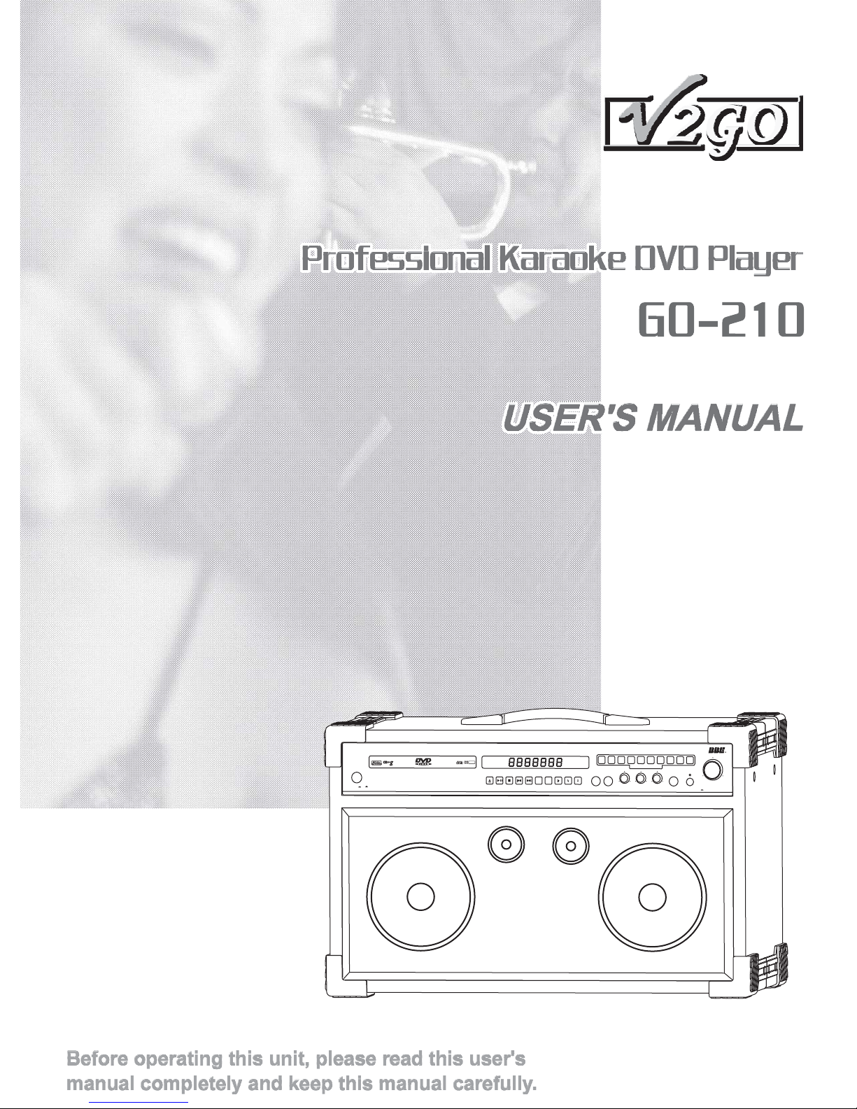
1
2
3
5
4
6
7
8
DOLBY
DIGITALAUDIO
DIGITAL
VOCAL
L/R
GO-210
On
Off
Professional KaraokeDVD Player
POWER
CANCEL
MIC1 MIC2
MIC1VOLMIC1VOL
DIRECTSEARCH SYSTEM
MIC2 VOL
MIC1 VOL
90
BBESOUND
MUSICVOL
On
ECHO
HEADPHONE
Page 2

TABLE OF CONTENTSTABLE OF CONTENTS
Warnings, Cautions and Safety-------------------------------------Warnings, Cautions and Safety-------------------------------------
Controls and Functions----------------------------------------------Controls and Functions----------------------------------------------
Introduction----------------------------------------------------------- 17
Introduction----------------------------------------------------------- 17
3
7
USB OperationPort and --------------------------------------------- 18USB OperationPort and --------------------------------------------- 18
AUX Speaker Connection------------------------------------------- 18AUX Speaker Connection------------------------------------------- 18
Play Modes-------------------------------------------------------------
Play Modes-------------------------------------------------------------
Functions and Operations-------------------------------------------Functions and Operations-------------------------------------------
19
20
Setup -------------------------------------------------------------------Setup -------------------------------------------------------------------
Specifications --------------------------------------------------------Specifications --------------------------------------------------------
Troubleshooting -----------------------------------------------------Troubleshooting -----------------------------------------------------
26
29
30
2
Page 3
WARNINGS, CAUTIONS AND OTHERSWARNINGS, CAUTIONS AND OTHERS
Mises en garde, precautions et indications diversesMises en garde, precautions et indications diverses
CAUTION
RISK OF ELECTRIC SHOCK
RISK OF ELECTRIC SHOCK
DO NOT OPEN
DO
NOT OPEN
CAUTION: TO REDUCETHE RISK OF ELECTRIC SHOCK.
CAUTION: TO REDUCETHE RISK OFELECTRIC SHOCK.
DO NOTREMOVE COVER (OR BACK).
NOT REMOVE COVER (OR BACK).
DO
NO USERSERVICEABLE PARTS INSIDE.
USER SERVICEABLE PAR TS INSIDE.
NO
REFER SERVICING TO QUALIFIED SERVICE PERSONNEL.
SERVICING TO QUALIFIED SERVICE PERSONNEL.
REFER
The lightning flash with arrowhead symbol, within an
The
lightning flash with arrowhead symbol, within an
equilateral triangle is intended to alert the user to the
equilateral
presence of uninsulated dangerous voltage within the
presence
product's enclosure that may be of sufficient magnitude
product's
to constitute a risk of electric shock to persons.
to
constitute a risk of electric shock to persons.
The exclamation point within an equilateral triangle is
The exclamation point within an equilateral triangle is
intended
intended to alert the user to the presence of important
operating
operating and maintenance (servicing) instructions in
the
the literature accompanying the appliance.
WARNING
WARNING
To reduce the risk of fire or electrical shock, do not
To reduce the risk of fire or electrical shock, do not
expose this appliance to rain or moisture.
expose
this appliance to rain or moisture.
FCC INFORMATION (U.S.A.)FCC INFORMATION (U.S.A.)
1.This equipment has been tested and found to
1.This equipment has been tested and found to
comply with the limits for a Class B digital device,
comply
pursuant
pursuant to part 15 of the FCC Rules. These
limits
limits are designed to provide reasonable
protection
protection against harmful interference in a
residential
residential installation.
This
This equipment generates, uses and can radiate
radio
radio frequency energy and, if not installed and
used
used in accordance with the instructions, may
cause
cause harmful interference to radio
communications.
communications. However, there is no guarantee
that
that interference will not occur in a particular
installation.
installation. If this equipment does cause harmful
interference
interference to radio or television reception,
which
which can be determined by turning the
equipment
equipment off and on, the user is encouraged to
try
try to correct the interference by one or more of
the
the following measures:
*Reorient
*Reorient or relocate the receiving antenna.
*Increase
*Increase the separation between the equipment
and
and receiver.
*Connect
*Connect the equipment into an outlet on a circuit
different
different from that to which the receiver is
connected.
connected. Consult the dealer or an experienced
radio/TV
radio/TV technician for help.
2. When connecting this product to
2. When connecting this product to
IMPORTANT:
IMPORTANT:
accessories and/or another product use only
accessories
high
high quality shielded cables. Cable(s) supplied
with
with this product MUST be used. Follow all
installation
installation instructions. Failure to follow
instructions
instructions could void your FCC authorization to
use
use product in the U. S. A.
with the limits for a Class B digital device,
are designed to provide reasonable
equipment generates, uses and can radiate
frequency energy and, if not installed and
in accordance with the instructions, may
harmful interference to radio
interference will not occur in a particular
can be determined by turning the
to correct the interference by one or more of
following measures:
receiver.
quality shielded cables. Cable(s) supplied
this product MUST be used. Follow all
product in the U. S. A.
triangle is intended to alert the user to the
of uninsulated dangerous voltage within the
enclosure that may be of sufficient magnitude
to alert the user to the presence of important
and maintenance (servicing) instructions in
literature accompanying the appliance.
to part 15 of the FCC Rules. These
against harmful interference in a
installation.
However, there is no guarantee
If this equipment does cause harmful
to radio or television reception,
off and on, the user is encouraged to
or relocate the receiving antenna.
the separation between the equipment
the equipment into an outlet on a circuit
from that to which the receiver is
Consult the dealer or an experienced
technician for help.
and/or another product use only
instructions. Failure to follow
could void your FCC authorization to
For Canada/Pour le Canada
For Canada/Pour le Canada
CAUTION: TO PREVENT ELECTRIC SHOCK,
CAUTION: TO PREVENT ELECTRIC SHOCK,
MATCH WIDE BLADE OF PLUG TO WIDE
MATCH
SLOT,AND FULLY INSERT.
SLOT,AND
ATTENTION:
ATTENTION:
ELECTRIQUES, INTRODUIRE LALAME LA PLUS
ELECTRIQUES,
LARGE DE LAFICHE DANS LABORNE
LARGE
CORRESPONDANTE DE LAPRISE ET POUSSER
CORRESPONDANTE
JUSQUAU FOND.
JUSQUAU
For Canada/Pour le Canada
For Canada/Pour le Canada
THIS DIGITALAPPARATUS DOES NOT EXCEED
THIS DIGITALAPPARATUS DOES NOT EXCEED
THE CLASS B LIMITS FOR RADIO NOISE
THE
EMISSIONS
EMISSIONS FORM DIGITALAPPARATUS AS SET
OUT IN THE
OUT IN THE INTERFERENCE-CAUSING
EQUIPMENT STANDARD
EQUIPMENT STANDARD ENTITLED DIGITAL
APPARATUS,
APPARATUS, ICES-003 OF THE DEPARTMENT
OF
OF COMMUNICATIONS. CET APPAREIL
NUMERIQUE
NUMERIQUE RESPECTE LES LIMITES DE
BRUITS
BRUITS RADIO ELECTRIQUESAPPLICABLES
AUX APPAREILS
AUX APPAREILS NUMERIQUES DE CLASSE B
PRESCRITES
PRESCRITES DANS LANORMESUR LE
MATERIEL BROUILLEUR: APPAREILS
MATERIEL BROUILLEUR: APPAREILS
NUMERIQUES
NUMERIQUES , NMB-003 EDICTEE PAR LE
MINISTRE
MINISTRE DES COMMUNICATIONS.
Caution
Caution
Disconnect the mains plug to shut the power off
Disconnect the mains plug to shut the power off
completely. The POWER is not disconnected from
completely. The
the
the mains line when the POWER button on the front
panel is
panel is pressed in.
WIDE BLADE OF PLUG TO WIDE
FULLY INSERT.
POUR EVITER LES CHOCS
POUR
EVITER LES CHOCS
INTRODUIRE LA LAME LA PLUS
DE LA FICHE DANS LA BORNE
DE LA PRISE ET POUSSER
FOND.
CLASS B LIMITS FOR RADIO NOISE
FORM DIGITALAPPARATUS AS SET
""
INTERFERENCE-CAUSING
"
ENTITLED DIGITAL
"
ICES-003 OF THE DEPARTMENT
COMMUNICATIONS. CETAPPAREIL
RESPECTE LES LIMITES DE
RADIO ELECTRIQUES APPLICABLES
NUMERIQUES DE CLASSE B
DANS LA NORMESUR LE
, NMB-003 EDICTEE PAR LE
DES COMMUNICATIONS.
POWER is not disconnected from
mains line when the POWER button on the front
pressed in.
IMPORTANT FOR LASER PODUCTSIMPORTANT FOR LASER PODUCTS
1.
1.
CLASS1
CLASS1 LASER PRODUCT
2. Visible laser radiation when open and
2. Visible
DANGER:
DANGER:
interlock
interlock failed or defeated. Avoid direct exposure
beam.
to
to beam.
3. Do
CATION:
3. Do not open the top cover. There are no
CATION:
user
user service able parts inside the unit. Leave all
servicing
servicing to qualified service personnel.
4. CAUTION
REPRODUCTION
4. CAUTION LABEL,
REPRODUCTION OF LABEL:
PLACED
PLACED INSIDE THE UNIT.
CERTIFICATION:
CERTIFICATION:
THIS PRODUCT COMPLIES WITH FDA RADIATION
THIS PRODUCT COMPLIES WITH FDA RADIATION
PERFORMANCE STANDARD, 21 CFR SUB.CHAPTER J.
PERFORMANCE
LASER PRODUCT
laser radiation when open and
failed or defeated.Avoid direct exposure
not open the top cover. There are no
service able parts inside the unit. Leave all
to qualified service personnel.
OF LABEL:
LABEL,
INSIDE THE UNIT.
PRODUCT COMPLIES WITH DHHS RULE 21
PRODUCT COMPLIES WITH DHHS RULE 21
CFR
SUB. CHAPTER J IN EFFECT AT DATE OF
CFRSUB.CHAPTERJINEFFECTATDATEOF
MANUFACTURE.
MANUFACTURE.
COMPLIES
COMPLIES WITH DHHS RADIATION
PERFORMANCE
PERFORMANCE STANDARDS, 21 CFR SUB.
CHAPTER
CHAPTER J.
STANDARD, 21 CFR SUB.CHAPTER J.
WITH DHHS RADIATION
STANDARDS, 21 CFR SUB.
J.
3
Page 4
SAFETY INSTRUCTIONS
Before using the unit, be sure to read all operating instructions carefully. Please note that
Before using the unit, be sure to read all operating instructions carefully. Please note that
these are general precautions and may not pertain to your unit.
these
1.
1.
2.
2.
3.
3.
4.
5.
5.
6.
6.
7.
7.
8.
8.
9.
9.
10.
10.
11.
11.
12.
12.
are general precautions and may not pertain to your unit.
Instructions
Read
Read Instructions
the safety and operating instructions should be read
All the safety and operating instructions should be read
All
before
before the product is operated.
The safety and operating instructions should be retained
The
for
for future reference.
All warnings on the product and in the operating
All
instructions
instructions should be adhered to.
the product is operated.
Retain
Retain Instructions
Heed
Heed Warnings
Follow
Follow Instructions4.
All operating and use instructions should be followed.
All
Attachments
Attachments
Do not use attachments not recommended by the
Do
product
product manufacturer as they may cause hazards.
Cleaning
Cleaning
Unplug this product from the wall outlet before cleaning.
Unplug
Do
Do not use liquid cleaners or aerosol cleaners. Use a dry
cloth
cloth for cleaning.
Ventilation
Ventilation
The appliance should be situated so its location does not
The
interfere
interfere with its proper ventilation. For example, the
appliance
appliance should not be situated on a bed, sofa, rug, or
similar
similar surface that may block the ventilation slots.
Heat
Heat
The appliance should be situated away from heat
The
sources
sources such as radiators, heat register, stoves, or other
apparatus
apparatus (including amplifiers) that produce heat.
Water
Water and Moisture
Do not use this unit near water. For example, near a
Do
bathtub
bathtub or in a wet basement and the like.
Power-supply cords should be routed so that they are
Power-supply
not
not likely to be walked on or pinched by items placed
upon
upon or against them, paying particular attention to
cords
cords at plugs, convenience receptacles, and point
where
where they exit from the appliance.
To protect your product from a lightning storm, or when it
To
is
is left unattended and unused for long periods of time,
unplug
unplug it from the wall outlet and disconnect the antenna
or
or cable system. This will prevent damage to the product
due
due to lightning and power-line surges.
The product should be used only with a cart
The
or
or stand that is recommended by the
manufacturer.
manufacturer.
Instructions
safety and operating instructions should be retained
future reference.
Warnings
warnings on the product and in the operating
should be adhered to.
Instructions
operating and use instructions should be followed.
not use attachments not recommended by the
manufacturer as they may cause hazards.
this product from the wall outlet before cleaning.
not use liquid cleaners or aerosol cleaners. Use a dry
for cleaning.
appliance should be situated so its location does not
with its proper ventilation. For example, the
should not be situated on a bed, sofa, rug, or
surface that may block the ventilation slots.
appliance should be situated away from heat
such as radiators, heat register, stoves, or other
(including amplifiers) that produce heat.
and Moisture
not use this unit near water. For example, near a
or in a wet basement and the like.
Power-cord
Power-cord Protection
likely to be walked on or pinched by items placed
or against them, paying particular attention to
at plugs, convenience receptacles, and point
they exit from the appliance.
Lightning
Lightning
protect your product from a lightning storm, or when it
left unattended and unused for long periods of time,
cable system. This will prevent damage to the product
to lightning and power-line surges.
Carts
Carts and Stands
product should be used only with a cart
stand that is recommended by the
Protection
cords should be routed so that they are
it from the wall outlet and disconnect the antenna
and Stands
Grounding
14.
14.
Grounding and Polarization
This product is equipped with a polarized alternating-
This
current
current line plug (a plug having one blade wider than the
other). This
other). This plug will fit into the power outlet only one
way. This
way. This is a safety feature. If you are unable to insert
plug fully into the outlet, try reversing the plug. If the
the
the plug fully into the outlet, try reversing the plug. If the
plug
plug should still fail to fit, contact your electrician to
replace
replace your obsolete outlet. Do not defeat the safety
purpose
purpose of the polarized plug.
Power
15.
15.
Power Lines
outside antenna system should not be located in the
An outside antenna system should not be located in the
An
vicinity
vicinity of overhead power lines or other electric light or
power
power circuits, or where it can fall into such power lines
circuits. When installing an outside antenna system,
or
or circuits. When installing an outside antenna system,
extreme
extreme care should be taken to keep from touching
such
such power lines or circuits as contact with them might
fatal.
be
be fatal.
Overloading
16.
16.
Overloading
not overload wall outlets, extension cords, or integral
Do not overload wall outlets, extension cords, or integral
Do
convenience
convenience receptacles as this can result in a risk of
fire
fire or electric shock.
Object
17.
17.
Object and Liquid Entry
Never push objects of any kind into this product through
Never
openings
openings as they may touch dangerous voltage points or
short-out
short-out parts that could result in a fire or electric
shock.
shock. Never spill liquid of any kind on the product.
Replacement
18.
18.
Replacement Parts
When replacement parts are required, be sure the
When
service
service technician has used replacement parts specified
the manufacturer or have the same characteristics as
by
by the manufacturer or have the same characteristics as
the
the original part. Unauthorized substitutions may result
fire, electric shock, or other hazards.
in
in fire, electric shock, or other hazards.
Safety
19.
19.
Safety Check
Upon completion of any service or repairs to this
Upon
product,
product, ask the service technician to perform safety
checks
checks to determine that the product is in proper
operating
operating condition.
Outdoor Antenna
20.
20.
Outdoor Antenna Grounding
an outside antenna or cable system is connected to the
If an outside antenna or cable system is connected to the
If
product,
product, be sure the antenna or cable system is
grounded
grounded so as to provide some protection against
voltage
voltage surges and built-up static charges.Article 810 of
National Electrical Code, ANSI/NFPA 70, provides
the
the National Electrical Code,ANSI/NFPA 70, provides
information
information with regard to proper grounding of the mast
and
and supporting structure, grounding of the lead-in wire to
antenna discharge unit, size of grounding conductors,
an
an antenna discharge unit, size of grounding conductors,
location
location of antenna discharge unit, connection to
grounding
grounding electrodes, and requirements for the
grounding
grounding electrode. See figure below.
and Polarization
product is equipped with a polarized alternating-
line plug (a plug having one blade wider than the
plug will fit into the power outlet only one
is a safety feature. If you are unable to insert
should still fail to fit, contact your electrician to
your obsolete outlet. Do not defeat the safety
of the polarized plug.
Lines
of overhead power lines or other electric light or
circuits, or where it can fall into such power lines
care should be taken to keep from touching
power lines or circuits as contact with them might
receptacles as this can result in a risk of
or electric shock.
and Liquid Entry
push objects of any kind into this product through
as they may touch dangerous voltage points or
parts that could result in a fire or electric
Never spill liquid of any kind on the product.
Parts
replacement parts are required, be sure the
technician has used replacement parts specified
original part. Unauthorized substitutions may result
Check
completion of any service or repairs to this
ask the service technician to perform safety
to determine that the product is in proper
condition.
Grounding
be sure the antenna or cable system is
so as to provide some protection against
surges and built-up static charges. Article 810 of
with regard to proper grounding of the mast
supporting structure, grounding of the lead-in wire to
of antenna discharge unit, connection to
electrodes, and requirements for the
electrode. See figure below.
A.
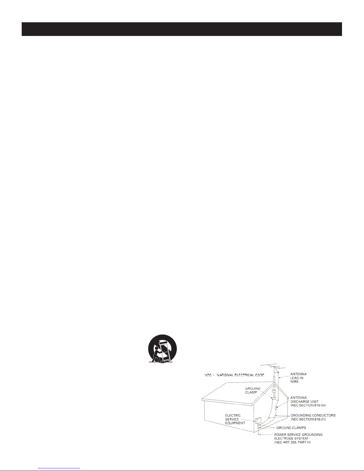
12 An applicance and cart combination should be moved
12 An applicance and cart combination should be moved
A.
care. Quick stops, excessive force and uneven
with care. Quick stops, excessive force and uneven
with
surfaces
surfaces may cause the appliance and cart combination
to
to overturn.
Power
13.
13.
Power Sources
product should be operated only from the type of power
product
source
source indicated on the marking label. If you are not
sure
sure of the type of power supply to your home, consult
your
your product dealer or local power company.
may cause the appliance and cart combination
overturn.
Sources
should be operated only from the type of power
indicated on the marking label. If you are not
of the type of power supply to your home, consult
product dealer or local power company.
4
Page 5

Damage
21.
21.
Damage Requiring Service
Unplug this product from the wall outlet and refer
Unplug
servicing
servicing to qualified service personnel under the
following
following conditions:
A.
When the power supply cord or plug is damaged.
A. When the power supply cord or plug is damaged.
If liquid has been spilled, or objects have fallen into
B.
B. If liquid has been spilled, or objects have fallen into
the
the product.
If the product has been exposed to rain or water.
C.
C. If the product has been exposed to rain or water.
If the product does not operate normally by following
D.
D. If the product does not operate normally by following
the
the operating instructions. Adjust only those controls
that
that are covered by the operating instructions as an
improper
improper adjustment of other controls may result in
damage
damage and will often require extensive work by a
qualified
qualified technician to restore the product to its normal
operation.
operation.
If the product has been dropped or damaged in any
E.
E. If the product has been dropped or damaged in any
way.
way.
When the product exhibits a distinct change in
F.
F. When the product exhibits a distinct change in
performance-this
performance-this indicates a need for service.
Note to CATV system installer
Note to CATV system installer
This reminder is provided to call the CATV system installers attention to Article 820-40
This
the NEC that provides guidelines for proper grounding and, in particular, specifies
of
of the NEC that provides guidelines for proper grounding and, in particular, specifies
that
that the cable ground shall be connected to the grounding system of the building, as
close
close to the point of cable entry as practical.
Requiring Service
this product from the wall outlet and refer
to qualified service personnel under the
conditions:
product.
operating instructions. Adjust only those controls
are covered by the operating instructions as an
adjustment of other controls may result in
and will often require extensive work by a
technician to restore the product to its normal
indicates a need for service.
Servicing
22.
22.
Servicing
not attempt to service it yourself as operating
Do not attempt to service it yourself as operating
Do
instructions,
instructions, do not attempt to service it yourself as
opening
opening or removing covers may expose you to
dangerous
dangerous voltage or other hazards. Refer all servicing
qualified service personal.
to
to qualified service personal.
do not attempt to service it yourself as
or removing covers may expose you to
voltage or other hazards. Refer all servicing
reminder is provided to call the CATV system installers attention to Article 820-40
the cable ground shall be connected to the grounding system of the building, as
to the point of cable entry as practical.
5
Page 6
Thank you for purchasing products from V2GO Technology!
V2GO Technology Inc., located in Los Angeles, CA, USA, is one of the
world's most innovative manufacturers of quality audio and video
electronic products. V2GO is proud of its strong R&D, quality control
and production resources that have resulted in a line of products that are
technologically advanced and are of superior quality and durability.
Providing quality products and services at a reasonable cost to the user
is the basis of V2GO's corporate philosophy. The ability to convert
intangible ideas into marketable products is V2GO's unchallenged
advantage. V2GO - Making your life a little more fun.
Contact us:
Interested in becoming a retailer or distributor of V2GO products?
Contact our sales department at [email protected]
For general information about V2GO products, contact us at
[email protected]
For Technical Assistance, email us at [email protected]
Monday to Friday, 8:30am to 5:30pm PST.
Please visit our website at www.V2GOTECH.com to find additional
information about V2GO products and services.
6
Page 7
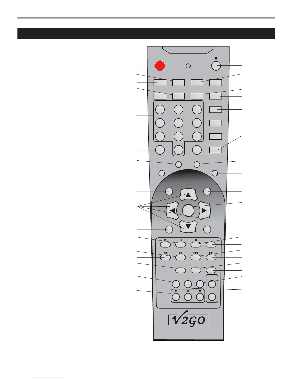
CONTROLS & FUNCTIONSCONTROLS & FUNCTIONS
Remote Control FunctionsRemote Control Functions
2.Mute
2.Mute
3.Eject
3.Eject
4.Karaoke
4.Karaoke
5.2 channel ( mode)
5.2
channel ( mode)
6.5.1channel ( )
6.5.1channel
7.Slow play
7.Slow
8.NTSC/PAL
8.NTSC/PAL
9.Video
9.Video
10.Audio
10.Audio
11.L/R
11.L/R
12.Numeric ke
12.Numeric
13.Time display
13.Time
14.OSD ( )
14.OSD
15.Program
15.Program
16. - ( epeat)
16. - ( epeat)
17.Clear
17.Clear
18.Search (
18.Search
19.Angle
19.Angle
20.PBC ( )
20.PBC
21.Subtitle
21.Subtitle
22.Title
22.Title
23.Setup
23.Setup
24.Direction
24.Direction
25.OK ( )
25.OK
26.Menu
26.Menu
27.Zoom
27.Zoom
28.Pause
28.Pause
29.Play
29.Play
30.Stop
30.Stop
31.Step
31.Step
32.Fast forward
32.Fast
33.Fast backward
33.Fast
34.Previous
34.Previous
35.Next
35.Next
36.Sound mode
36.Sound
38.Vocal cancel
38.Vocal
39.EQ
39.EQ
40.Return
40.Return
41.View
41.View
42.Volume
42.Volume
43. Key control
43.
44.Random
44.Random
selector
selector
A B section r
A B section
()
Key control
stereo
stereo
surround sound mode
()
surround
sound mode
play
selector
selector
ypad
ypad
ke
display
on screen display
on
()
screen display
r
DVD/USB switch)
DVD/USB
(
playback control
playback
()
al selector
al
selector
confirm
confirm
switch)
control
forward
backward
mode
cancel
2
4
7
8
9
12
15
18
20
22
24
26
28
29
32
33
36
40
43
MUTE
SLOW KARAOKE 2CH 5.1CH
VIDEO N/P AUDIO L/R
1
4
7
PBC SUBTITLE
23
5
89
0
SEARCH ANGLE
TITLE SETUP
MENU ZOOM
SOUND
SOUND
MODE
MODE
RETURN RANDOM VIEW VOL+
6
CLEARPROGRAM A-B
OK
VOCAL
VOCAL
CANCEL
CANCEL
TIME
OSD
REPEAT
STEP
EQ
VOL-
3
5
6
10
11
13
14
16
17
19
21
23
25
27
30
31
34
35
38
39
41
42
44
7
Page 8
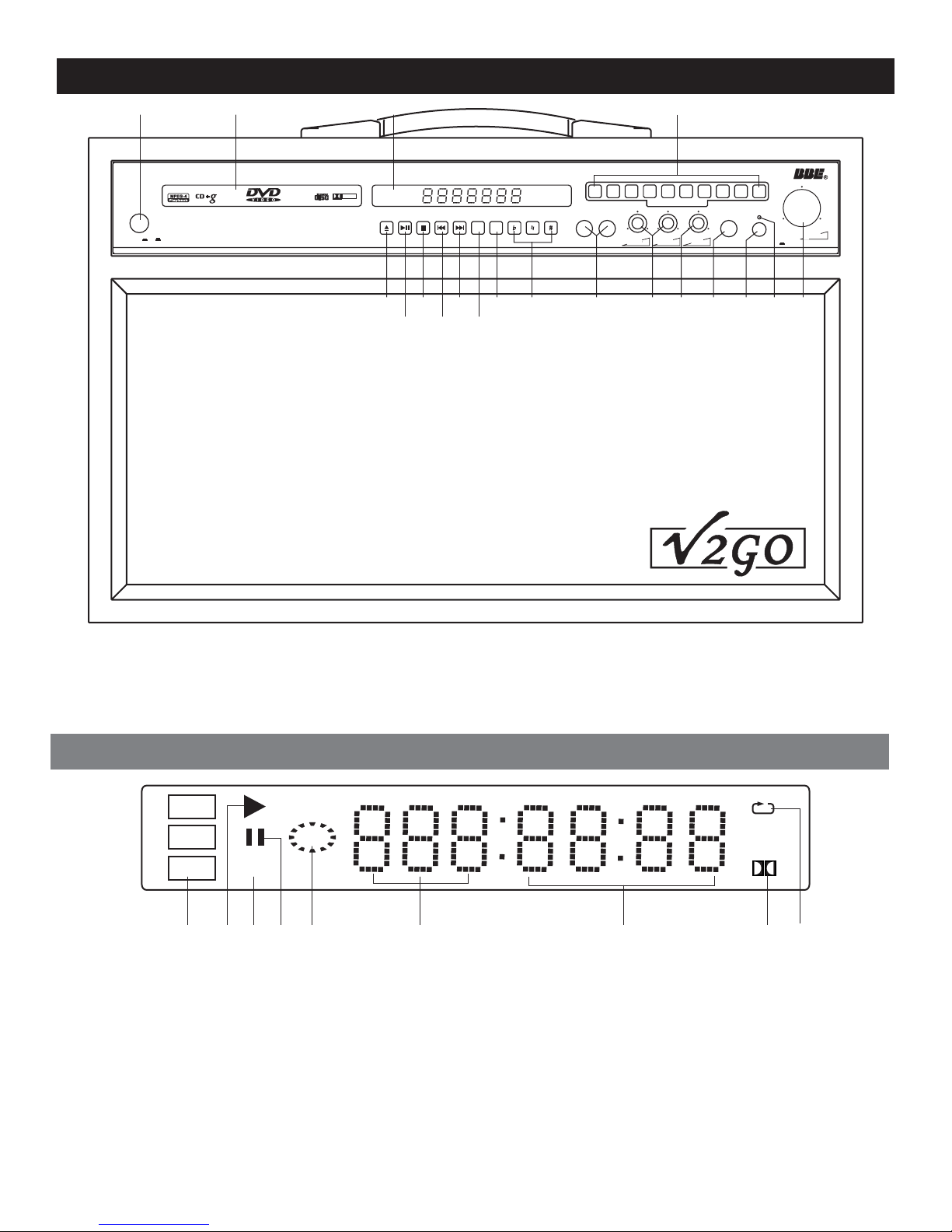
Front Panel FunctionsFront Panel Functions
1
POWER On Off
45 46 12
GO-210
Professional KaraokeDVD PlayerProfessional KaraokeDVD Player
DIGITALAUDIO
DOLBY
DIGITAL
5
7
6
3
4
2
1
VOCAL
VOCAL
L/R
CANCEL
CANCEL
DIRECTSEARCH SYSTEMDIRECTSEARCH SYSTEM
MIC2VOLMIC 2 VOL
MIC1 VOLMIC1 VOLMIC 1VOLMIC 1 VOL MIC1VOLMIC1 VOL
35303
8
9 0
ECHOMIC1MIC1 MIC 2MIC2 HEADPHONE BBESOUNDBBESOUND On
MUSICVOLMUSICVOL
52 5351504948474338
113428/29
1.Power On/Off
1.Power On/Off
3.Eject button
3.Eject
button
11.L/R button
11.L/R
button
12.Numeric keys 0-9
12.Numeric
28/29.Play/Pause button
28/29.Play/Pause
keys 0-9
button
DVD
VCD
Mp3
1 42 3 5 6 7 8
1.Disc type
1.Disc type
2.In PLAY status
2.In
PLAY status
3.PBC on
3.PBC
on
4.In Pause status
4.In
Pause status
5.Playback
5.Playback
6.Tray information
6.Tray
information
7.Time information
7.Time
information
8.Dolby on
8.Dolby
9.In Repeat status
9.In
on
Repeat status
PBC
30.Stop button
30.Stop button
34.Previous button
34.Previous
35.Next button
35.Next
38.Vocal cancel
38.Vocal
43.Key control buttons
43.Key
button
button
cancel
control buttons
LED Display WindowLED Display Window
45.Tray door
45.Tray door
46.LED display window
46.LED
47.Microphone jacks
47.Microphone
48.MIC1/2 volume
48.MIC1/2
49.Echo button
49.Echo
display window
jacks
volume
button
50.Headphone jack
50.Headphone jack
51.BBE sound ON
51.BBE
52.BBE sound indicator
52.BBE
53.Music volume
53.Music
sound ON
sound indicator
volume
D
9
8
Page 9
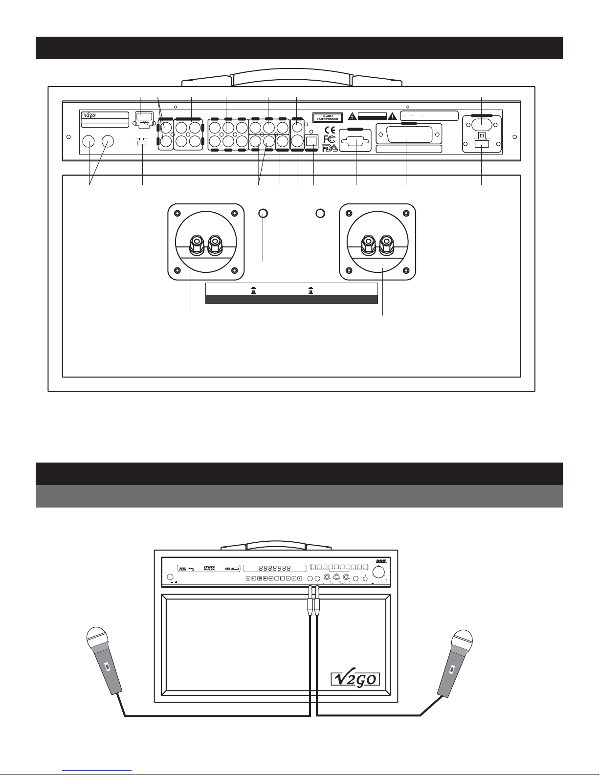
Rear Panel FunctionsRear Panel Functions
KaraokeDVD PlayerKaraokeDVD Player
MODELNO.: GO-210MODELNO.: GO-210
INPUT:~110V/230V 50/60HzINPUT: ~110V/230V 50/60Hz
LACALIFORNIA U.S.A
MIC1 MIC 2MIC 2
MIC1
20
Madein ChinaMade in China
14
USB
AUX DVD
19
10 2 3 1211 1
KARAOKEOUTPUTKARAOKEOUTPUTAUXINPUTAUXINPUT
L
R R
- + - +
15
COAXIAL
VIDEO
S-VIDEO OPTICAL
Y/R PB/G PR/B
SL SR
SWFL FR
ML MR
CEN
L
4 65 7 9 13
16
AUX ON
Right AUXSpeakerRight AUXSpeaker
AUX SpeakerImpedance: 6-16 OHMS; AUX SpeakerPower Consumption: >80 WAUX SpeakerImpedance: 6-16 OHMS;AUX SpeakerPower Consumption: > 80W
AUX ON
OFF
AUX OFF
AUX
18
AUX ON
AUX ON
OFF
AUX OFF
AUX
Left AUXSpeakerLeft AUXSpeaker
RISKOF ELECTRIC SHOCK
RISKOF ELECTRIC SHOCK
VGA
8
CAUTION
DONOT OPEN
DO
NOTOPEN
SerialNumber:SerialNumber:
17
1.Manufacturedunder license fromDolby Laboratories.
1.Manufacturedunder license fromDolby Laboratories.
Dolby, Pro Logic and thedouble-D symbol are
2.Dolby , Pro Logic and thedouble-D symbol are
2.
trademarks
trademarksof Dolby Laboratories.
ofDolby Laboratories.
SCART
~110V
POWERINPUTPOWER INPUT
~230V
POWERSELECTPOWERSELECT
1.5.1 Channel audio output jacks
1.5.1 Channel audio output jacks
2.Y.PB.PR. Video output jacks
2.Y.PB.PR.
3.Composite video output jack
3.Composite
4.2 channel audio output jacks
4.2
channel audio output jacks
5.Coaxial output jack
5.Coaxial
Video output jacks
video output jack
output jack
6.S-video output jack
6.S-video output jack
7.Optical output jack
7.Optical
8.VGA output jack
8.VGA
9.SCART output jack
9.SCART
10.Karaoke output jacks
10.Karaoke
output jack
output jack
output jack
output jacks
1 . put jacks
12.Power cord connection
12.Power
13.Power select
13.Power
14.USB jack
14.USB
15.Right AUX speaker connector
15.Right
in
cord connection
select
jack
AUX speaker connector
16.Right AUX speaker switch button
16.Right AUX speaker switch button
17.Left AUX speaker connector
17.Left
AUX speaker connector
18.Left AUX speaker switch button
18.Left
AUX speaker switch button
19.AUX / DVD switch button
19.AUX
20.Microphone jacks
20.Microphone
/ DVD switch button
jacks
1AUXin
1AUX
1 . put jacks
Connection
Microphone ConnectionMicrophone Connection
There are total four microphone jacks on the machine, two in the front panel and two in the back panel.
There are total four microphone jacks on the machine, two in the front panel and two in the back panel.
the microphone cable into jacks.
Plug the microphone cable into jacks.
Plug
5
6 7 8
POWEROn Off
GO-210
ProfessionalKaraoke DVD PlayerProfessionalKaraoke DVDPlayer
3
2
DOLBY
DIGITAL
DIGITALAUDIO
VOCAL
VOCAL
L/R
CANCEL
CANCEL
1
MIC1VOLMIC1VOLMIC1VOLMIC1VOL MIC 1VOLMIC 1 VOL
4
DIRECTSEARCHSYSTEMDIRECTSEARCHSYSTEM
MIC2VOLMIC 2 VOL
9 0
ECHOMIC1MIC1 MIC 2MIC2 HEADPHONE BBESOUNDBBESOUNDOn
MUSICVOLMUSICVOL
9
Page 10
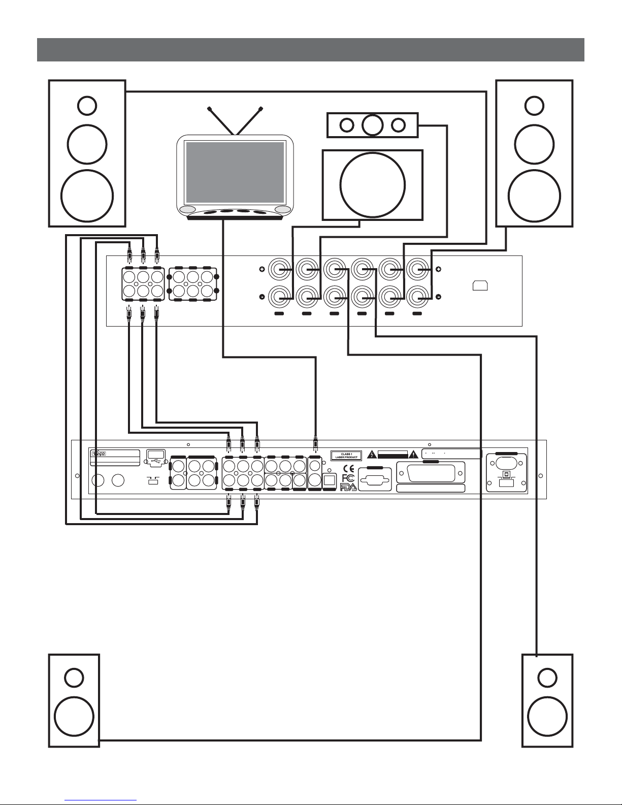
Home Theatre ConnectionHome Theatre Connection
CEN
FL
MODELNO.: GO-210MODELNO.: GO-210
INPUT:~110V/230V 50/60HzINPUT: ~110V/230V 50/60Hz
LACALIFORNIA U.S.A
MIC1
MIC1 MIC 2MIC 2
FL FR
KaraokeDVD PlayerKaraokeDVD Player
Madein ChinaMade in China
CENSL SR
L
R
SW
5.1 Channel AV Amplifier
5.1 Channel AV Amplifier
USB
L
AUX DVD
R R
DVDTUN CD
TUN
DVD
CD
KARAOKEOUTPUTKARAOKEOUTPUTAUXINPUTAUXINPUT
FR
TV
SW
L
R
SW CEN SL SR FL FR
GO-210
1.Manufacturedunder license fromDolby Laboratories.
SerialNumber:SerialNumber:
1.Manufacturedunder license fromDolby Laboratories.
2.Dolby , Pro Logic and thedouble-D symbol are
2.
Dolby, Pro Logic and thedouble-D symbol are
trademarksof Dolby Laboratories.
trademarks
SCART
CAUTION
RISKOF ELECTRIC SHOCK
RISKOF ELECTRIC SHOCK
DONOT OPEN
DO
NOTOPEN
VGA
COAXIAL
VIDEO
S-VIDEO OPTICAL
Y/R PB/G PR/B
SL SR
SWFL FR
ML MR
CEN
L
ofDolby Laboratories.
~100V-240V(50-60Hz)
~110V
POWERINPUTPOWER INPUT
~230V
POWERSELECTPOWERSELECT
SL
SR
10
Page 11
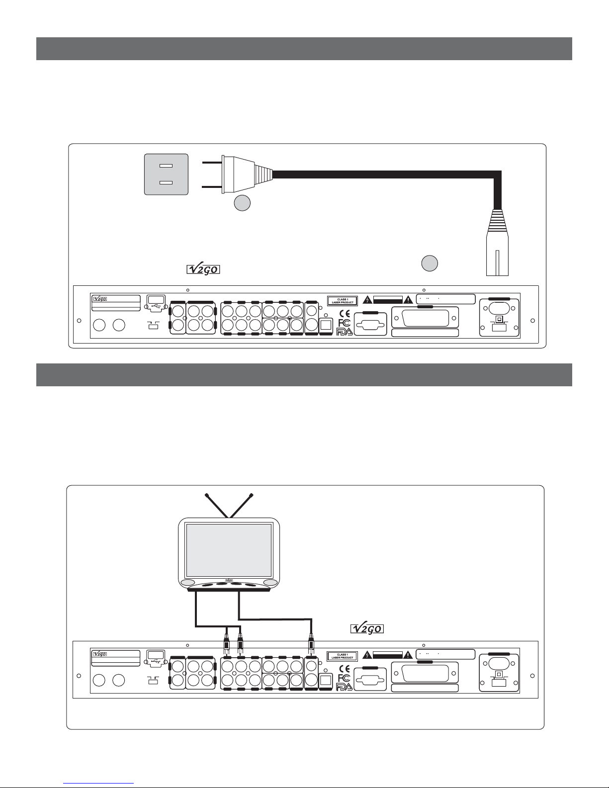
Power Cord ConnectionPower Cord Connection
1. Connect the power cable to the DVD player first.
1. Connect the power cable to the DVD player first.
Connect the power plug to the outlet.
2. Connect the power plug to the outlet.
2.
NOTE: Please check whether the voltage of your local power lines match this machine voltage range
NOTE: Please check whether the voltage of your local power lines match this machine voltage range
(110V/240V) before getting connected.
(110V/240V)
WARNING: Please be sure that the power button is positioned at OFF after use.
WARNING: Please be sure that the power button is positioned at OFF after use.
Please unplug the power cord if nonuse for a long time.
Please
before getting connected.
unplug the power cord if nonuse for a long time.
2
GO-210
L
SL SR
SWFL FR
CEN
Y/R PB/G PR/B
COAXIAL
ML MR
VIDEO
S-VIDEO OPTICAL
RISKOF ELECTRIC SHOCK
RISKOF ELECTRIC SHOCK
VGA
CAUTION
DONOT OPEN
DO
NOTOPEN
SerialNumber:SerialNumber:
1
1.Manufacturedunder license fromDolby Laboratories.
1.Manufacturedunder license fromDolby Laboratories.
2.Dolby , Pro Logic and thedouble-D symbol are
2.
Dolby, Pro Logic and thedouble-D symbol are
trademarksof Dolby Laboratories.
trademarks
ofDolby Laboratories.
SCART
~110V
POWERINPUTPOWER INPUT
~230V
POWERSELECTPOWERSELECT
KaraokeDVD PlayerKaraokeDVD Player
MODELNO.: GO-210MODELNO.: GO-210
INPUT:~110V/230V 50/60HzINPUT: ~110V/230V 50/60Hz
LACALIFORNIA U.S.A
MIC1 MIC 2MIC 2
MIC1
AC120V/240V
AC120V/240V
50Hz/60Hz
50Hz/60Hz
Madein ChinaMade in China
USB
AUX DVD
KARAOKEOUTPUTKARAOKEOUTPUTAUXINPUTAUXINPUT
L
R R
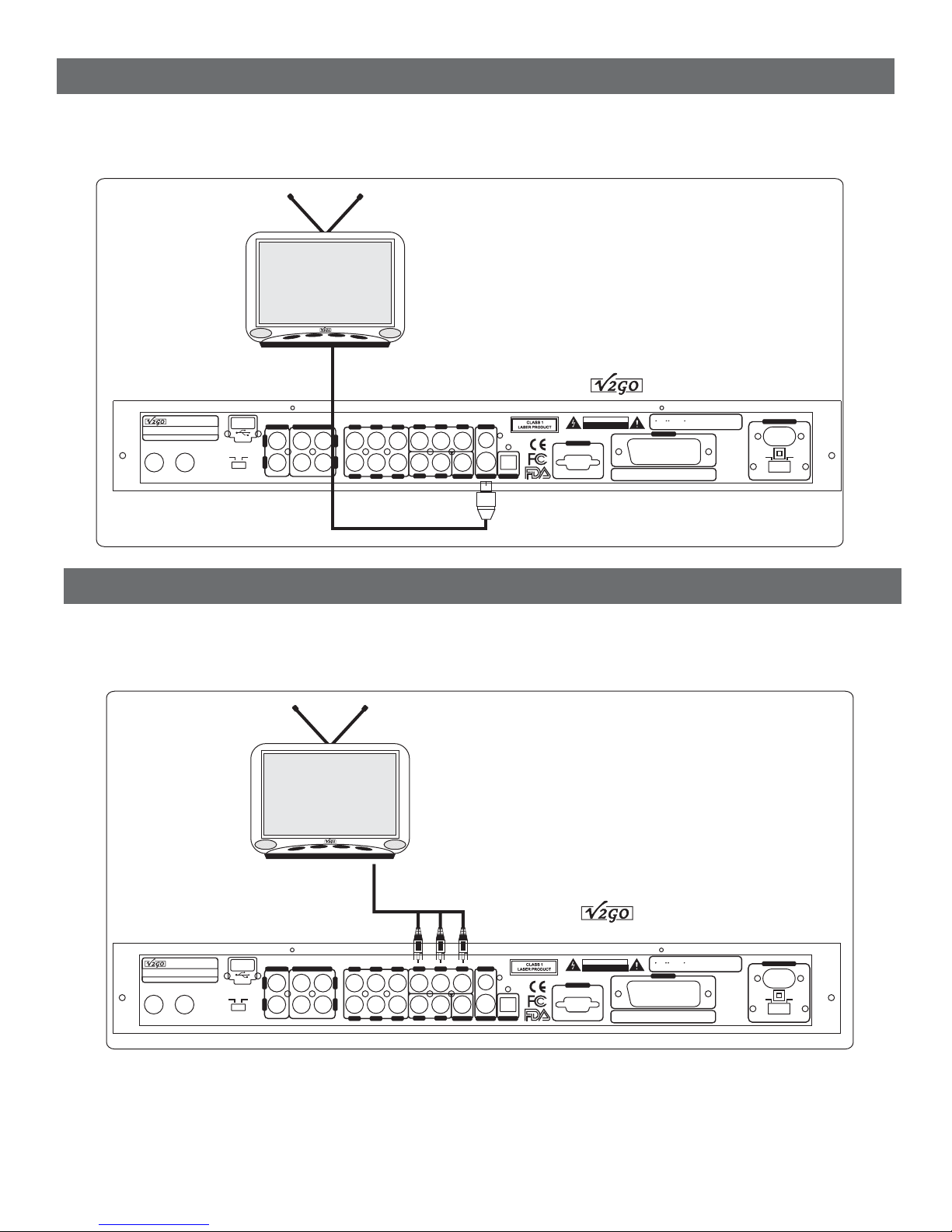
Composite Video Output ConnectionComposite Video Output Connection
Apply Video Cord (the one with yellow head) to connect VIDEO OUT jack on GO-210 with
Apply Video Cord (the one with yellow head) to connect VIDEO OUT jack on GO-210 with
VIDEO IN jack on TV.
VIDEO
Apply Audio
Apply Audio Cord (white and red head) to connect AUDIO OUT jacks (ML, MR) on GO-210 with AUDIO IN
jack
jack on TV.
IN jack on TV.
Cord (white and red head) to connect AUDIO OUT jacks (ML, MR) on GO-210 withAUDIO IN
on TV.
: This is only applied to a standard TV with AV function while playing disc.NOTE: This is only applied to a standard TV withAV function while playing disc.NOTE
TO-TV AUDIO INTO-TV AUDIO IN
KaraokeDVD PlayerKaraokeDVD Player
MODELNO.: GO-210MODELNO.: GO-210
INPUT:~110V/230V 50/60HzINPUT: ~110V/230V 50/60Hz
LACALIFORNIA U.S.A
MIC1
MIC1 MIC 2MIC 2
Madein ChinaMade in China
USB
AUX DVD
KARAOKEOUTPUTKARAOKEOUTPUTAUXINPUTAUXINPUT
L
R R
TO-TV VIDEO INTO-TV VIDEO IN
GO-210
1.Manufacturedunder license fromDolby Laboratories.
SerialNumber:SerialNumber:
1.Manufacturedunder license fromDolby Laboratories.
2.Dolby , Pro Logic and thedouble-D symbol are
2.
Dolby, Pro Logic and thedouble-D symbol are
trademarksof Dolby Laboratories.
trademarks
ofDolby Laboratories.
SCART
~110V
POWERINPUTPOWER INPUT
~230V
POWERSELECTPOWERSELECT
CAUTION
RISKOF ELECTRIC SHOCK
RISKOF ELECTRIC SHOCK
DONOT OPEN
DO
NOTOPEN
VGA
COAXIAL
VIDEO
S-VIDEO OPTICAL
Y/R PB/G PR/B
SL SR
SWFL FR
ML MR
CEN
L
11
Page 12
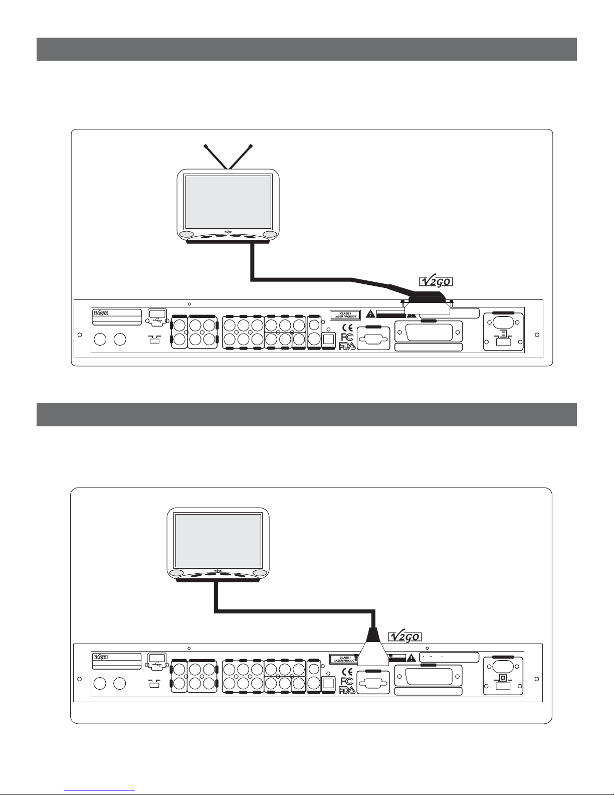
S-VIDEO ConnectionS-VIDEO Connection
Apply S-VIDEO Cord to connect S-VIDEO OUTPUT jack on GO-210 with S-VIDEO IN jack on TV.
Apply S-VIDEO Cord to connect S-VIDEO OUTPUT jack on GO-210 with S-VIDEO IN jack on TV.
The TV should be set in S-VIDEO mode. Player setting is shown on PAGE 20.
The TV
should be set in S-VIDEO mode. Player setting is shown on PA GE 20.
TO TV S-VIDEO INTO TV S-VIDEO IN
KaraokeDVD PlayerKaraokeDVD Player
MODELNO.: GO-210MODELNO.: GO-210
INPUT:~110V/230V 50/60HzINPUT: ~110V/230V 50/60Hz
LACALIFORNIA U.S.A
MIC1 MIC 2MIC 2
MIC1
Madein ChinaMade in China
USB
AUX DVD
KARAOKEOUTPUTKARAOKEOUTPUTAUXINPUTAUXINPUT
L
R R
COAXIAL
VIDEO
S-VIDEO OPTICAL
Y/R PB/G PR/B
SL SR
SWFL FR
ML MR
CEN
L
RISKOF ELECTRIC SHOCK
RISKOF ELECTRIC SHOCK
VGA
CAUTION
DONOT OPEN
DO
NOTOPEN
SerialNumber:SerialNumber:
GO-210
1.Manufacturedunder license fromDolby Laboratories.
1.Manufacturedunder license fromDolby Laboratories.
2.Dolby , Pro Logic and thedouble-D symbol are
2.
Dolby, Pro Logic and thedouble-D symbol are
trademarksof Dolby Laboratories.
ofDolby Laboratories.
trademarks
SCART
POWERINPUTPOWER INPUT
~110V
POWERSELECTPOWERSELECT
~230V
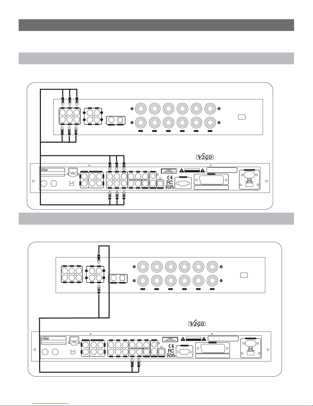
Y.Pb.Pr ConnectionY. P b . P r Connection
Apply Y.Pb.Pr cords to connect Y.Pb.Pr jacks on GO-210 with Y.Pb.Pr IN jacks on the TV.Apply Y. Pb . Pr cords to connect Y. Pb . Pr jacks on GO-210 with Y.Pb.Pr IN jacks on the TV.
TV should be set in Y.Pb.Pr mode. For player setting, please see PAGE 20.TV should be set in Y.Pb.Pr mode. For player setting, please see PA GE 20.
TO-TV Y.Pb.Pr INTO-TV Y.Pb.Pr IN
GO-210
1.Manufacturedunder license fromDolby Laboratories.
SerialNumber:SerialNumber:
1.Manufacturedunder license fromDolby Laboratories.
2.Dolby , Pro Logic and thedouble-D symbol are
2.
Dolby, Pro Logic and thedouble-D symbol are
trademarksof Dolby Laboratories.
trademarks
ofDolby Laboratories.
SCART
KaraokeDVD PlayerKaraokeDVD Player
MODELNO.: GO-210MODELNO.: GO-210
INPUT:~110V/230V 50/60HzINPUT: ~110V/230V 50/60Hz
LACALIFORNIA U.S.A
MIC1
MIC1 MIC 2MIC 2
Madein ChinaMade in China
USB
AUX DVD
KARAOKEOUTPUTKARAOKEOUTPUTAUXINPUTAUXINPUT
L
R R
CAUTION
RISKOF ELECTRIC SHOCK
RISKOF ELECTRIC SHOCK
DONOT OPEN
DO
NOTOPEN
VGA
COAXIAL
VIDEO
S-VIDEO OPTICAL
Y/R PB/G PR/B
SL SR
SWFL FR
ML MR
CEN
L
~110V
POWERINPUTPOWER INPUT
~230V
POWERSELECTPOWERSELECT
12
Page 13
SCART Connection
This is for TV with SCART jack. You need a SCART cord and you will get audio and video output. Apply a
This is for TV with SCART jack. You need a SCART cord and you will get audio and video output. Apply a
SCART cord to connect SCART OUTPUT jack on GO-210 with SCART IN jack on TV.
SCART cord
The TV
The TV should be set in SCART mode. Player setting is shown on PAGE 20.
to connect SCART OUTPUT jack on GO-210 with SCART IN jack on TV.
should be set in SCART mode. Player setting is shown on PA GE 20.
TO-TV SCART INTO-TV SCART IN
KaraokeDVD PlayerKaraokeDVD Player
MODELNO.: GO-210MODELNO.: GO-210
INPUT:~110V/230V 50/60HzINPUT: ~110V/230V 50/60Hz
LACALIFORNIA U.S.A
MIC1
MIC1 MIC 2MIC 2
Madein ChinaMade in China
USB
AUX DVD
KARAOKEOUTPUTKARAOKEOUTPUTAUXINPUTAUXINPUT
L
R R
COAXIAL
VIDEO
S-VIDEO OPTICAL
Y/R PB/G PR/B
SL SR
SWFL FR
ML MR
CEN
L
RISKOF ELECTRIC SHOCK
RISKOF ELECTRIC SHOCK
VGA
CAUTION
DONOT OPEN
DO
NOTOPEN
SerialNumber:SerialNumber:
GO-210
1.Manufacturedunder license fromDolby Laboratories.
1.Manufacturedunder license fromDolby Laboratories.
Dolby, Pro Logic and thedouble-D symbol are
2.Dolby , Pro Logic and thedouble-D symbol are
2.
trademarks
trademarksof Dolby Laboratories.
ofDolby Laboratories.
SCART
~110V
POWERINPUTPOWER INPUT
~230V
POWERSELECTPOWERSELECT
VGA Connection
Apply VGA cord to connect VGA jack on GO-210 with TV/MONITOR. You will get a better picture from this
Apply VGA cord to connect VGA jack on GO-210 with TV/MONITOR. You will get a better picture from this
progressive scan function. Player setting is shown on PAGE 20.
progressive
scan function. Player setting is shown on PAGE 20.
TV /
TV /
MONITOR
MONITOR
TO-PC VGA INTO-PC VGA IN
KaraokeDVD PlayerKaraokeDVD Player
MODELNO.: GO-210MODELNO.: GO-210
INPUT:~110V/230V 50/60HzINPUT: ~110V/230V 50/60Hz
LACALIFORNIA U.S.A
MIC1 MIC 2MIC 2
MIC1
Madein ChinaMade in China
USB
AUX DVD
KARAOKEOUTPUTKARAOKEOUTPUTAUXINPUTAUXINPUT
L
R R
Y/R PB/G PR/B
SL SR
SWFL FR
ML MR
CEN
L
COAXIAL
VIDEO
S-VIDEO OPTICAL
RISKOF ELECTRIC SHOCK
RISKOF ELECTRIC SHOCK
VGA
CAUTION
DONOT OPEN
DO
NOTOPEN
SerialNumber:SerialNumber:
GO-210
1.Manufacturedunder license fromDolby Laboratories.
1.Manufacturedunder license fromDolby Laboratories.
Dolby, Pro Logic and thedouble-D symbol are
2.Dolby , Pro Logic and thedouble-D symbol are
2.
trademarks
trademarksof Dolby Laboratories.
ofDolby Laboratories.
SCART
~110V
POWERINPUTPOWER INPUT
~230V
POWERSELECTPOWERSELECT
13
Page 14
AUDIO CONNECTIONAUDIO CONNECTION
There are 6 ways to connect the GO-210 with different machines. In addition, GO-210 is an all-in one
There are 6 ways to connect the GO-210 with different machines. In addition, GO-210 is an all-in one
machine with amplifier and speaker.
machine
with amplifier and speaker.
5.1 Channel output (surround sound)5.1 Channel output (surround sound)
Apply a set of cords to connect the FL. FR. SL. SR. CEN and SW jacks on G0-210 with 5.1 channel amplifier.Apply a set of cords to connect the FL. FR. SL. SR. CEN and SW jacks on G0-210 with 5.1 channel amplifier.
FR SR
CENFL SL
SW
DVDCD
L
R
L
R
DVD
CD
COAXIAL
OPTICAL
SW CEN SL SR FL FR
~100V-240V(50-60Hz)
5.1 channel AV amplifier5.1 channel AV amplifier
GO-210
1.Manufacturedunder license fromDolby Laboratories.
SerialNumber:SerialNumber:
1.Manufacturedunder license fromDolby Laboratories.
2.Dolby , Pro Logic and thedouble-D symbol are
2.
Dolby, Pro Logic and thedouble-D symbol are
trademarksof Dolby Laboratories.
trademarks
ofDolby Laboratories.
SCART
~110V
POWERINPUTPOWER INPUT
~230V
POWERSELECTPOWERSELECT
KaraokeDVD PlayerKaraokeDVD Player
MODELNO.: GO-210MODELNO.: GO-210
INPUT:~110V/230V 50/60HzINPUT: ~110V/230V 50/60Hz
LACALIFORNIA U.S.A
MIC1 MIC 2MIC 2
MIC1
Madein ChinaMade in China
USB
AUX DVD
KARAOKEOUTPUTKARAOKEOUTPUTAUXINPUTAUXINPUT
L
R R
CAUTION
RISKOF ELECTRIC SHOCK
RISKOF ELECTRIC SHOCK
DONOT OPEN
DO
NOTOPEN
VGA
COAXIAL
VIDEO
S-VIDEO OPTICAL
Y/R PB/G PR/B
SL SR
SWFL FR
ML MR
CEN
L
2 Channel Stereo output2 Channel Stereo output
Apply Audio Cord (white and red head) to connect AUDIO OUT (ML, MR) jacks on GO-210 with DVD jacks on
Apply Audio Cord (white and red head) to connect AUDIO OUT (ML, MR) jacks on GO-210 with DVD jacks on
HIFI amplifier. Music output only.
amplifier. Music output only.
HIFI
KaraokeDVD PlayerKaraokeDVD Player
MODELNO.: GO-210MODELNO.: GO-210
INPUT:~110V/230V 50/60HzINPUT: ~110V/230V 50/60Hz
LACALIFORNIA U.S.A
MIC1 MIC 2MIC 2
MIC1
Madein ChinaMade in China
FR SR
AUX DVD
CENFL SL
SW
USB
L
R R
DVDCD
L
R
L
R
DVD
CD
KARAOKEOUTPUTKARAOKEOUTPUTAUXINPUTAUXINPUT
L
COAXIAL
SL SR
OPTICAL
SWFL FR
CEN
SW CEN SL SR FL FR
Stereo HIFI amplifierStereo HIFI amplifier
RISKOF ELECTRIC SHOCK
Y/R PB/G PR/B
COAXIAL
ML MR
VIDEO
S-VIDEO OPTICAL
RISKOF ELECTRIC SHOCK
VGA
14
CAUTION
DONOT OPEN
DO
NOTOPEN
SerialNumber:SerialNumber:
GO-210
1.Manufacturedunder license fromDolby Laboratories.
1.Manufacturedunder license fromDolby Laboratories.
Dolby, Pro Logic and thedouble-D symbol are
2.Dolby , Pro Logic and thedouble-D symbol are
2.
trademarks
trademarksof Dolby Laboratories.
ofDolby Laboratories.
SCART
~100V-240V(50-60Hz)
POWERINPUTPOWER INPUT
~110V
POWERSELECTPOWERSELECT
~230V
Page 15
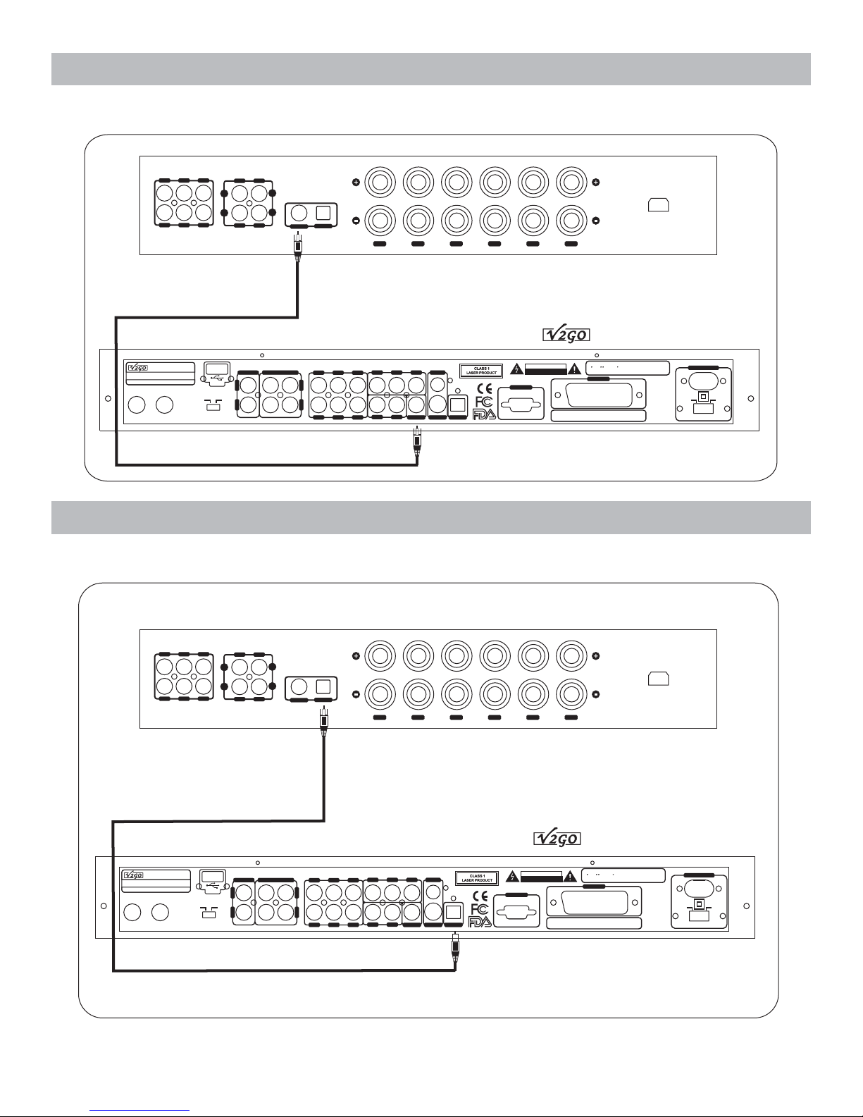
Coaxial outputCoaxial output
Apply a Coaxial cord to connect the digital amplifier / decoder with GO-210 on COAXIAL jacks.Apply a Coaxial cord to connect the digital amplifier / decoder with GO-210 on COAXIAL jacks.
FR SR
CENFL SL
SW
DVDCD
L
R
L
R
DVD
CD
COAXIAL
OPTICAL
SW CEN SL SR FL FR
~100V-240V(50-60Hz)
5.1 channel digital amplifier5.1 channel digital amplifier
GO-210
1.Manufacturedunder license fromDolby Laboratories.
SerialNumber:SerialNumber:
1.Manufacturedunder license fromDolby Laboratories.
2.Dolby , Pro Logic and thedouble-D symbol are
2.
Dolby, Pro Logic and thedouble-D symbol are
trademarksof Dolby Laboratories.
trademarks
ofDolby Laboratories.
SCART
KaraokeDVD PlayerKaraokeDVD Player
MODELNO.: GO-210MODELNO.: GO-210
INPUT:~110V/230V 50/60HzINPUT: ~110V/230V 50/60Hz
LACALIFORNIA U.S.A
MIC1
MIC1 MIC 2MIC 2
Madein ChinaMade in China
USB
AUX DVD
KARAOKEOUTPUTKARAOKEOUTPUTAUXINPUTAUXINPUT
L
R R
CAUTION
RISKOF ELECTRIC SHOCK
RISKOF ELECTRIC SHOCK
DONOT OPEN
DO
NOTOPEN
VGA
COAXIAL
VIDEO
S-VIDEO OPTICAL
Y/R PB/G PR/B
SL SR
SWFL FR
ML MR
CEN
L
Optical outputOptical output
Apply an Optical cord to connect digital amplifier / decoder with GO-210 on OPTICAL jacks.Apply an Optical cord to connect digital amplifier / decoder with GO-210 on OPTICAL jacks.
~110V
POWERINPUTPOWER INPUT
~230V
POWERSELECTPOWERSELECT
FR SR
KaraokeDVD PlayerKaraokeDVD Player
MODELNO.: GO-210MODELNO.: GO-210
INPUT:~110V/230V 50/60HzINPUT: ~110V/230V 50/60Hz
LACALIFORNIA U.S.A
MIC1 MIC 2MIC 2
MIC1
Madein ChinaMade in China
CENFL SL
SW
USB
AUX DVD
DVDCD
L
R
L
R
DVD
CD
KARAOKEOUTPUTKARAOKEOUTPUTAUXINPUTAUXINPUT
L
R R
COAXIAL
L
OPTICAL
SL SR
SW CEN SL SR FL FR
5.1 channel digital amplifier5.1 channel digital amplifier
COAXIAL
VIDEO
S-VIDEO OPTICAL
SWFL FR
CEN
Y/R PB/G PR/B
ML MR
15
RISKOF ELECTRIC SHOCK
RISKOF ELECTRIC SHOCK
VGA
CAUTION
DONOT OPEN
DO
NOTOPEN
SerialNumber:SerialNumber:
~100V-240V(50-60Hz)
GO-210
1.Manufacturedunder license fromDolby Laboratories.
1.Manufacturedunder license fromDolby Laboratories.
2.Dolby , Pro Logic and thedouble-D symbol are
2.
Dolby, Pro Logic and thedouble-D symbol are
trademarksof Dolby Laboratories.
trademarks
ofDolby Laboratories.
SCART
~110V
POWERINPUTPOWER INPUT
~230V
POWERSELECTPOWERSELECT
Page 16
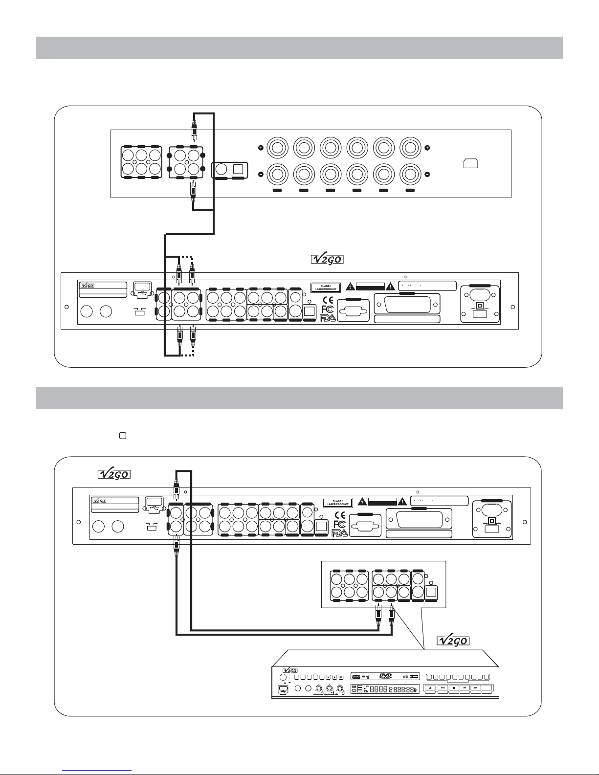
Karaoke outputKaraoke output
Apply Audio Cord (red and white head) to connect KARAOKE OUTPUT jacks on the back of GO-210 with
Apply Audio Cord (red and white head) to connect KARAOKE OUTPUT jacks on the back of GO-210 with
STEREO INPUT jacks on amplifier. Under this KARAOKE entertainment mode, mixed music and vocal are output.
STEREO
INPUT jacks on amplifier. Under this KARAOKE entertainment mode, mixed music and vocal are output.
FR SR
CENFL SL
SW
DVDCD
L
R
L
R
DVD
CD
COAXIAL
OPTICAL
SW CEN SL SR FL FR
~100V-240V(50-60Hz)
5.1 channel AV amplifier5.1 channel AV amplifier
GO-210
1.Manufacturedunder license fromDolby Laboratories.
SerialNumber:SerialNumber:
1.Manufacturedunder license fromDolby Laboratories.
2.Dolby , Pro Logic and thedouble-D symbol are
2.
Dolby, Pro Logic and thedouble-D symbol are
trademarksof Dolby Laboratories.
trademarks
ofDolby Laboratories.
SCART
~110V
POWERINPUTPOWER INPUT
~230V
POWERSELECTPOWERSELECT
KaraokeDVD PlayerKaraokeDVD Player
MODELNO.: GO-210MODELNO.: GO-210
INPUT:~110V/230V 50/60HzINPUT: ~110V/230V 50/60Hz
LACALIFORNIA U.S.A
MIC1 MIC 2MIC 2
MIC1
Madein ChinaMade in China
USB
AUX DVD
KARAOKEOUTPUTKARAOKEOUTPUTAUXINPUTAUXINPUT
L
R R
CAUTION
RISKOF ELECTRIC SHOCK
RISKOF ELECTRIC SHOCK
DONOT OPEN
DO
NOTOPEN
VGA
COAXIAL
VIDEO
S-VIDEO OPTICAL
Y/R PB/G PR/B
SL SR
SWFL FR
ML MR
CEN
L
AUX audio inputAUX audio input
GO-210 could connect with external audio source through AUX input jacks on the back panel when the
GO-210 could connect with external audio source through AUX input jacks on the back panel when the
function selector beside is switched toAUX status.
function
selector beside is switched to AUX status.
19
KaraokeDVD PlayerKaraokeDVD Player
MODELNO.: GO-210MODELNO.: GO-210
INPUT:~110V/230V 50/60HzINPUT: ~110V/230V 50/60Hz
LACALIFORNIA U.S.A
MIC1 MIC 2MIC 2
MIC1
GO-210
Madein ChinaMade in China
USB
AUX DVD
KARAOKEOUTPUTKARAOKEOUTPUTAUXINPUTAUXINPUT
L
R R
1.Manufacturedunder license fromDolby Laboratories.
SerialNumber:SerialNumber:
COAXIAL
1.Manufacturedunder license fromDolby Laboratories.
2.Dolby , Pro Logic and thedouble-D symbol are
2.
Dolby, Pro Logic and thedouble-D symbol are
trademarksof Dolby Laboratories.
trademarks
ofDolby Laboratories.
SCART
VIDEO
S-VIDEO OPTICAL
~110V
POWERINPUTPOWER INPUT
~230V
POWERSELECTPOWERSELECT
CAUTION
RISKOF ELECTRIC SHOCK
RISKOF ELECTRIC SHOCK
DONOT OPEN
DO
VGA
SWFL FR
CEN
NOTOPEN
Y/R PB/G PR/B
ML MR
COAXIAL
VIDEO
S-VIDEO OPTICAL
SL SR
Y/R PB/G PR/B
SL SR
SWFL FR
ML MR
CEN
L
GO-100
KaraokeDVD PlayerKaraokeDVD PlayerGO-100
KaraokeDVD PlayerKaraokeDVD PlayerGO-100
DVD
POWEROn Off
POWEROn Off
DVD
VOCAL
VOCAL
VOCAL
VOCAL
AUDIO
AUDIO
MENU
MENU
L/R
L/R
CANCEL
CANCEL
CANCEL
CANCEL
USB
USB
MIC1VOLMIC1 VOL
MIC1VOLMIC1 VOL
MIC2VOLMIC2VOL
MIC1MIC1 MIC2MIC2
MIC1MIC1 MIC2MIC2
USB
USB
MIC2VOLMIC2VOL
CD
CD
ALL
ALL
VCD
VCD
Mp3
Mp3
ECHO
ECHO
DOLBY
DOLBY
DIGITAL
DIGITAL
DIGITALAUDIO
DIGITALAUDIO
OPEN/CLOSE
OPEN/CLOSE
5
5
678
678
3
3
4
4
2
2
1
1
DIRECTSEARCHSYSTEMDIRECTSEARCHSYSTEM
DIRECTSEARCHSYSTEMDIRECTSEARCHSYSTEM
PLAY/PAUSE
PLAY/PAUSE
STOP
STOP
9 0
9 0
PREV NEXT PROGRAM
PREV NEXT PROGRAM
PROGRAM
PROGRAM
PROGRAM
PROGRAM
CD+G
CD+G
CD+G
CD+G
16
Page 17
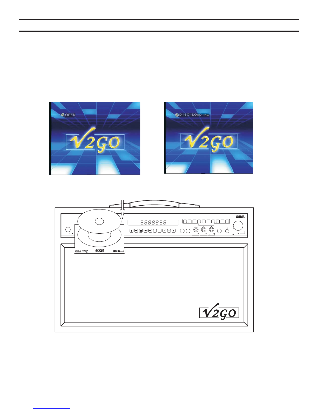
INTRODUCTION
Your V2GO GO-210 is a multi-format disc player with a built-in stereo amplifier and speakers.
Simply connect your unit to a power source and you are ready to begin listening to CDs or singing
karaoke. Connecting your GO-210 to a television allows you to see the karaoke music's lyrics
and access menu options, or to watch a DVD movie.
1. Connect the power cord on your to an electrical outlet as previously described.
2. Connect the video output on your to your television as previously described.
3. Press the POWER button on the .
GO-210
GO-210
GO-210
Tray ejectTray eject Reading discReading disc
5
6 7 8
POWER On Off
GO-210
Professional KaraokeDVD PlayerProfessionalKaraoke DVD Player
3
4
2
1
DIRECTSEARCH SYSTEMDIRECT SEARCH SYSTEM
VOCAL
VOCAL
L/R
CANCEL
CANCEL
MIC2VOLMIC2 VOL
MIC1VOLMIC1 VOLMIC1VOLMIC1 VOL MIC 1VOLMIC1 VOL
9 0
ECHOMIC1MIC1 MIC 2MIC2 HEADPHONE BBE SOUNDBBESOUND On
MUSICVOLMUSICVOL
DOLBY
DIGITAL
DIGITALAUDIO
4. Once playing, use the remote control to directly access songs or chapters using the numeric
keypad.
5. Adjust the volume using the volume control on the front of the GO-210 or using the Vol + and
Vol – buttons (#42, pg.7) on your remote control.
17
Page 18
USB PORT AND OPERATIONUSB PORT AND OPERATION
The USB port on the back of your GO-210 provides the option to play files recorded on a USB flash
drive or hard drive in Mp3, WMA, JPEG, AVI and VCD formats.
If no disc is in the disc tray, the GO-210 automatically loads data from the USB device.
If the player is playing a disc, press the STOP (#30, pg.7) button to stop playing before connecting
a USB flash drive or hard drive. Once the USB flash drive or hard drive is connected, press the
USB/DISC button. The root directory of the connected USB device will display on the connected
television after a few seconds. Use the remote control's directional buttons (24) to select the file
you want to play. Press the ENTER (25) button to start playing from the attached USB device.
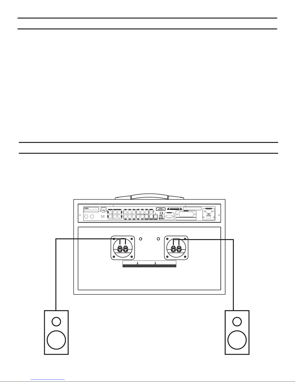
AUX SPEAKER CONNECTIONAUX SPEAKER CONNECTION
Your GO-210 allows you the option to connect a pair of independent speakers to
the Auxiliary speaker connectors (#15 and #17, pg. 9) located on the back of the unit.
The Auxiliary speaker switch buttons (#16 and #17, pg 9) control the output from your GO-210.
When switched OFF, output is directed to the unit's internal speakers, and
When switched ON, output is directed to external speakers (if connected).
KaraokeDVD PlayerKaraoke DVDPlayer
MODELNO.:GO-210MODELNO.: GO-210
INPUT:~110V/230V 50/60HzINPUT: ~110V/230V 50/60Hz
LACALIFORNIAU.S.A
MIC1
MIC1 MIC2MIC2
MadeinChinaMadeinChina
AUX DVD
USB
L
R R
Dolby, Pro Logic andthe double-Dsymbol are
RISKOFELECTRIC SHOCK
RISKOFELECTRIC SHOCK
trademarksofDolby Laboratories.
trademarks
DONOTOPEN
VIDEO
SL SR
SWFL FR
CEN
Y/R PB/G PR/B
ML MR
COAXIAL
S-VIDEO OPTICAL
KARAOKEOUTPUTKARAOKE OUTPUTAUXINPUTAUXINPUT
L
DO
VGA
ofDolbyLaboratories.
NOTOPEN
SCART
SerialNumber:SerialNumber:
~110V
POWERINPUTPOWER INPUT
POWERSELECTPOWER SELECT
~230V
1.Manufacturedunderlicense from DolbyLaboratories.
1.Manufacturedunderlicense from DolbyLaboratories.
CAUTION
2.Dolby, ProLogic andthe double-Dsymbol are
2.
- + - +
AUXON
AUXON
RightAUX SpeakerRightAUX Speaker
AUXON
OFF
AUXOFF
AUX
AUXSpeaker Impedance: 6-16OHMS ; AUXSpeaker Power Consumption:> 80 WAUXSpeaker Impedance: 6-16OHMS ;AUX SpeakerPowerConsumption: > 80 W
AUXON
AUXOFF
AUX
OFF
LeftAUX SpeakerLeftAUX Speaker
Right speakerRight speaker Left speakerLeft speaker
18
Page 19
PLAY MODES
4
Karaoke ModeKaraoke Mode
This mode is used for karaoke entertainment. Using your remote control, press the STOP button
(30). Press the KARAOKE button (4) to enter the karaoke mode. In the karaoke mode, the CD or
CD+G disc stops automatically at the end of each song. The PLAY button (29) must be pressed
for the next song. The KEY control (43) is activated only in the karaoke mode. If the key of a song
is changed, the GO-210 will reset the key to neutral at the end of the song.
NOTE: If your GO-210 is connectedto an external amplification system, the karaoke music with microphone will only be available
at the aux OUTPUT connectors on the backof the unit.
5
Stereo ModeStereo Mode
With the player stopped, press STEREO button (5) on the remote control to enter this mode. The television
screen will display Stereo. Stereo is the recommended mode for enjoying high fidelity music.
NOTE: In the stereo mode, music is available at the ML, MR, FL, FR and KARAOKE OUTPUT jacks.
6
5.1 Channel Mode5.1 Channel Mode
With the player stopped, press 5.1 CH button (6) on the remote control. The television screen will
display 5.1 CH. This mode allows for full surround sound viewing when connected to an external
surround sound amplifier and speaker system.
NOTE: In the 5.1 channel mode, there will be audio available at the ML, MR, FL, FR, CEN, SL, SR and SW
jacks when playing a DOLBY 5.1 channel disc.
15
Program ModeProgram Mode
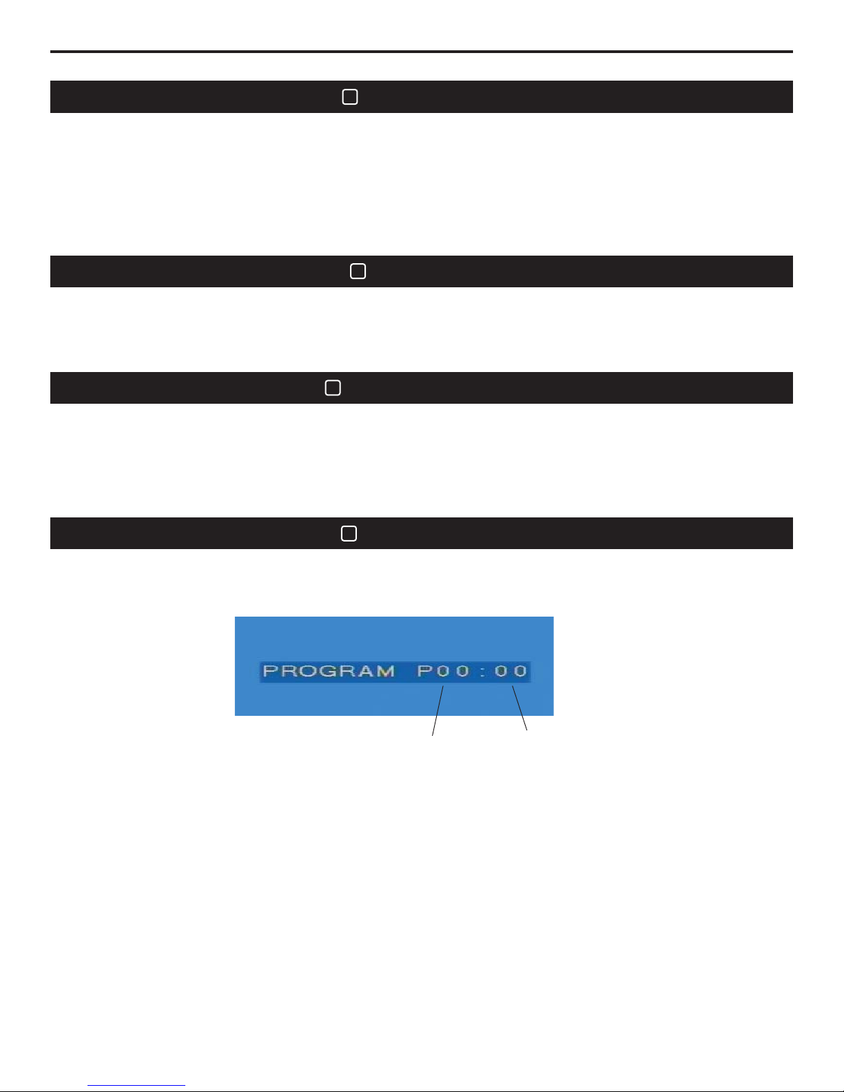
Press STOP button when the machine finish reading disc. Then press PROGRAM button to enter this mode.
Press STOP button when the machine finish reading disc. Then press PROGRAM button to enter this mode.
can select playing order of tracks or choose tracks you want to play. The PROG word will light up on VFD
You can select playing order of tracks or choose tracks you want to play. The PROG word will light up on VFD
You
the mode is on. This program function is inapplicable for DVD, MP3 or VCD 2.0 discs.
when
when the mode is on. This program function is inapplicable for DVD, MP3 or VCD 2.0 discs.
Play orderPlay order
The Program Mode allows the user to program the playback sequence of tracks played. The program
mode will not function with DVD, MP3 or VCD 2.0 discs.
1. Insert a CD, MP3 or CD-G disc into the player. Wait a few seconds for the player to read the contents
of the disc.
2. Press the STOP button (30).
3. Press PROGRAM button (15) to begin programming.
4. Select the desired track number using the remote control's numeric keypad (12). Each time a track
has been selected, the track number will display on the connected video monitor.
5. Press the ENTER button (25) each time a track has been chosen to confirm the choice. Each time the
ENTER button is pressed the track number will be added to the playback sequence.
6. In the event a track needs to be removed, press the CLEAR button (17) immediately after the
incorrect track is entered.
7. Repeat step 4 and 5 to add additional tracks to the playback sequence.
8. Press the STOP button twice to exit the Program Mode.
9. Press the PLAY button (29) to begin the sequential play back of the programmed tracks.
Programmed track numberProgrammed track number
19
Page 20

FUNCTIONS AND OPERATIONSFUNCTIONS AND OPERATIONS
38
Vocal CancelVocal Cancel
Vocal Cancel button controls four switches to VOCAL CANCEL RIGHT, VOCAL CANCEL LEFT, VOCAL
Vocal Cancel button controls four switches to VOCALCANCEL RIGHT, VOCAL CANCEL LEFT, VOCAL
PARTNER RIGHT and VOCAL PARTNER LEFT.
PAR TN ER
Press once for VOCAL CANCEL RIGHT select to cancel the vocal coming from karaoke disc s right
Press once
channel.
channel.
Press twice for VOCAL CANCEL LEFT select to cancel the vocal coming from karaoke disc s left channel.
Press twice
Press three times for VOCAL PARTNER RIGHT the leader voice from karaoke disc s right
Press three
channel disappears automatically when singer s voice comes out through microphone.
channel
Press four times for VOCAL PARTNER LEFT the leader voice from karaoke disc s left channel disappears
Press four
automatically when singer s voice comes out through microphone.
automatically when
Press fifth time to cancel function. Note: The function is applicable for karaoke discs only.
Press fifth
The Key Control buttons (43) are typically used only with karaoke discs, although it can be used at
anytime in the karaoke mode. The Key Control buttons change the key of the playback music up
and down in ½ steps, allowing the singer to sing in a key comfortable for his or her voice. The Ь
button lowers the key while the # button raises the key. Neither button changes the speed of the
music. Neither button affects the microphone(s).
Once your video monitor is connected to the GO-210, select the correct video for your display as
follows:
RIGHT and VOCAL PARTNER LEFT.
for VOCAL CANCEL RIGHT select to cancel the vocal coming from karaoke disc s right
for VOCAL CANCEL LEFT select to cancel the vocal coming from karaoke disc s left channel.
times for VOCAL PARTNER RIGHT the leader voice from karaoke disc s right
disappears automatically when singer s voice comes out through microphone.
times for VOCAL PARTNER LEFT the leader voice from karaoke disc s left channel disappears
singer s voice comes out through microphone.
’
’
time to cancel function. Note: The function is applicable for karaoke discs only.
–’
–’
–’
–’
–’
–’
’
’
–’
–’
43
Key ControlKey Control
9
Video Output SelectVideo Output Select
A.S-VIDEO: for S-VIDEO connection
A.S-VIDEO:
B.YC C :
br br
B.YC C : for YC C connection
br br
C.SCRAT:for SCRAT connection
C.SCRAT:for
br br
D.YP P : for YP P connection
br br
D.YP P :
E.VGA: for VGA connection, can connect to a PC monitor
E.VGA:
for S-VIDEO connection
for YC C connection
SCRAT connection
for YP P connection
for VGA connection, can connect to a PC monitor
1. Depress the Stop button (30).
2. Depress the Video button (9).
3. Within 2 seconds depress the Enter button (25).
4. Repeat this process as many times as necessary to get the video type necessary for proper
display on your monitor.
51
BBE Audio EffectBBE Audio Effect
The GO-210 is equipped with a BBE Sonic Maximizer®. This button turns the BBE Sonic Maximizer
on and off.
50
Headphone OutputHeadphone Output
A headphone jack (#50, pg 8) is located on the front panel of your GO-210. The amplifier of the
machine shuts down automatically and audio is redirected when a headphone is connected. The
headphone volume is adjusted by the MUSIC VOLUME knob(#53, pg 8) located on the front panel of
the unit.
20
Page 21

8
Video Type SelectVideo Type Select
The N/P button (8) is used to switch between NTSC and PAL video format discs.
5. Depress the Stop button (30).
6. Depress the N/P button (8).
7. Within 2 seconds depress the Enter button (25).
8. Repeat this process as many times as necessary to get the video type necessary for proper
display on the attached video monitor.
This process allows the user to choose between MULTI, SYSTEM, NTSC and PAL. Settings for
480P, 576P, and 720P (HDTV only) should be selected in the SETUP menu described later.
NOTE: Occasionally when adjusting the GO-210’s settings, the user may create a situation
where the system needs to be reset to factory defaults because the user may no longer be able to
view system information on the video monitor. To reset all functions to the factory default:
1. Turn the power off using the Power button on the GO-210.
2. Turn the Power back on.
3. Press the eject button on the GO-210.
4. Using the GO-210’s front panel numeric keys, enter 222888
5. Press the Stop button (30)
6. Turn the power off using the Power button on the GO-210.
7. Turn the Power back on.
10
Audio OutputAudio Output
The Audio Output button (10) is used with DVD discs to access different audio modes available on
the DVD.
11
Audio Playback ModeAudio Playback Mode
The R/L button (11) is used when playing CD, CD-G, VCD and MP3 format discs to select the
audio playback mode. Available modes are mono, left, right and stereo.
21
Page 22

16
Repeat ModeRepeat Mode
The Repeat mode is comprised of 2 buttons (both shown as 14); the Repeat and the A/B buttons.
When playing a disc, press the Repeat button once and the connected monitor will display Rept 1,
indicting that the current song or chapter will repeat until the Stop button (30) is pressed.
Pressing the Repeat button again will cause the entire disc to repeat until the Stop button (30) is
pressed. Pressing Repeat again returns the mode to full disc play and stop. This mode is
available with any type of disc.
The A-B mode button allows the user to select a starting point and ending point to repeat within a
DVD chapter. This function will only work with DVD discs. While playing a DVD disc, press the AB button immediately followed by the Enter button (25) at the point that the section is to be
repeated from. Continue playing until the end of the section is reached and press A/B
immediately followed by the Enter button (25). The selected section will play repeatedly until
either the A-B button or the Stop button (30) is pressed. Function not applicable with CD+G discs.
12
Numeric ButtonNumeric Button
Direct numeric access buttons are used to enter song or chapter numbers between 1 and 999.
Combinations of digits must be entered within 5 seconds of each other. Numbers entered that
exceed the number of tracks or chapters on the disc playing will be ignored.
24
Directional Arrows
Direct numeric access buttons are used to enter song or chapter numbers between 1 and 999.
Combinations of digits must be entered within 5 seconds of each other. Numbers entered that
exceed the number of tracks or chapters on the disc playing will be ignored.
27
Zoom ButtonZoom Button
The Zoom button (27) is used to magnify the image on the attached video monitor. The image
size is increased by a factor of 1.5x, 2x and 3x. Once an image is magnified, the Direction buttons
(24) may be used to move the magnified image across the connected video monitor. When
displaying JPEG images, use the ◄◄ (33) button to zoom out and the ►► (32) button to zoom
in. The JPEG image may be rotated using the Direction buttons (24).
18
Search PlaySearch Play
The Search button (18) is used to select specific titles and chapters within a DVD disc. When the
Search button is pressed a search dialog will appear on the connected video monitor. Use the
right and left arrows to select Chapter or Title. Use the numeric keypad to enter specific Chapter
and Title numbers, followed by the Enter button (25). With the Musicarrier stopped and a USB
device connected, the Search button may be pressed to display the root directory of the USB
device. This function is inapplicable to CD+G discs.
31
Step ButtonStep Button
The Step button (31) causes the DVD to pause playback. Once paused, each time the Step
button is pressed the DVD will scan forward 1 frame. Press the Play button (29) to resume
35
34
Previous And NextPrevious And Next
&
The Previous button (34) allows the user to interrupt the currently playing track or chapter and
skip backwards to the beginning of the currently playing track. The Next button (35) allows the
user to interrupt the currently playing track or chapter and skip forwards to the beginning of the
next track.
22
Page 23

32
33
Backward And ForwardBackward And Forward
&
The Fast Forward button (32) allows the user to quickly move forward within the currently playing
track or chapter. The Fast Forward will increase the speed each time it is pressed – 2x, 4x, 6x
and 8x, and then returning to normal play. The Fast Reverse button (33) allows the user to quickly
move backwards within the currently playing track or chapter. The Fast Reverse will increase the
speed each time it is pressed – 2x, 4x, 6x and 8x, and then returning to normal play.
NOTE: This function is disabled when playing CD-G karaoke discs.
36
Sound ModeSound Mode
Select the sound field you like in the Karaoke Mode. There are 5 modes.Select the sound field you like in the Karaoke Mode. There are 5 modes.
7
Slow PlaySlow Play
The Slow button (7) allows the user to slow the playback speed of DVDs and VCDs. While
⅛
playing a DVD, pressing this button allows the user to slow down the playback to ½ or ormal
n
speed in either the forward or backward direction. When playing VCD discs the Slow button will
⅛
slow the playback to ½ or peed but only in the forward direction. Press the Slow button once
for ½ speed and a second time for peed. Pressing the Slow button again will result in normal
s
⅛
s
play. When the GO-210 is playing in the slow mode, the audio output is disabled.
44
Random PlayRandom Play
Press RANDOM button to enter this mode when stop playing. The SHUFFLE ON will be shown on the
Press RANDOM button to enter this mode when stop playing. The SHUFFLE ON will be shown on the
screen. The playing order of the songs is random now. Press RANDOM button again to cancel play randomly.
screen. The
The SHUFFLE OFF will be shown. Then press PLAY button to play orderly.
SHUFFLE OFF will be shown. Then press PLAY button to play orderly.
The
NOTE: This function is applicable for CD CD+G and VCD1.0 discs. Under this random mode, numeric
NOTE: This
access buttons stop working.
access
playing order of the songs is random now. Press RANDOM button again to cancel play randomly.
function is applicable for CD CD+G and VCD1.0 discs. Under this random mode, numeric
buttons stop working.
23
Page 24
39
EQ(Equalizer)
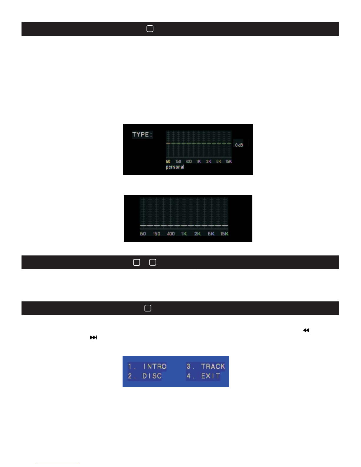
The EQ button (39) allows the user to customize the sound of music or other playback material to suite
their tastes. Pressing the EQ button turns the equalizer on. Pressing the EQ button a second time
displays the Dynamic Frequency Spectrum. Pressing the EQ button a third time turns the equalizer off.
Preset and custom equalization modes are available. Press the EQ button once to turn the EQ on. Press
either the Enter (25) or the Play (29) button to enter the custom EQ settings. A total of 8 EQ settings are
available – Standard, Classic, Jazz, Rock, Pop, Ballad, Dance and Personal. In the Personal setting the
user may adjust each band of the EQ as desired. The EQ level of each band is adjusted with the Up and
Down directional buttons (24). Shifting from one band to another is accomplished using the Right and Left
directional buttons (24). Once adjustments are complete, press the EQ button to save and select the
Personal setting.
Personal settingPersonal setting
Dynamic fr quency spectrum display:eDynamic fr quency spectrum display:e
The frequency trends of the music audio show as below.The frequency trends of the music audio show as below.
Dynamic frequency spectrum displayDynamic frequency spectrum display
13 &13 &
14
Time & OSD DisplayTime & OSD Display
Press the TIME button to display the current selected track and time information. Four display types
Press the TIME button to display the current selected track and time information. Four display types
available: Single track time C, Title time T, Timing from start and count down. Press the OSD button to
available:
display
display the OSD time.
Press the VIEW button when stop playing the VCD disc. The screen displays as below. You can choose
Press the VIEW button when stop playing the VCD disc. The screen displays as below. You can choose
items with the numeric keys and press OK button to confirm. When viewing the scenes, press button
the items with the numeric keys and press OK button to confirm. When viewing the scenes, press button
the
previous page and button to the next.
to
to previous page and button to the next.
1.Intro: Preview the beginnings, only 9 seconds for each song. This function is applicable for VCD2.0 disc
1.Intro: Preview the beginnings, only 9 seconds for each song. This function is applicable for VCD2.0 disc
under PCB OFF status.
under
2. Disc view
2. Disc view
screen will be divided into 9 scenes to show the image of the beginning 9 seconds of every song.
The screen will be divided into 9 scenes to show the image of the beginning 9 seconds of every song.
The
Choose
Choose your desired track with the numeric keys.
3. Track
3. Track view: The screen will be divided into 9 scenes to show the images of the beginning, 9 seconds of each
songs
songs . Choose to play from your selected segment with the numeric keys.
Exit: Press to exit this 9 scenes view function.
4.
4. Exit: Press to exit this 9 scenes view function.
Single track time C, Titl e time T, Timing from start and count down. Press the OSD button to
the OSD time.
41
9 Pictures View9 Pictures View
PCB OFF status.
your desired track with the numeric keys.
view: The screen will be divided into 9 scenes to show the images of the beginning, 9 seconds of each
. Choose to play from your selected segment with the numeric keys.
17
24
Page 25
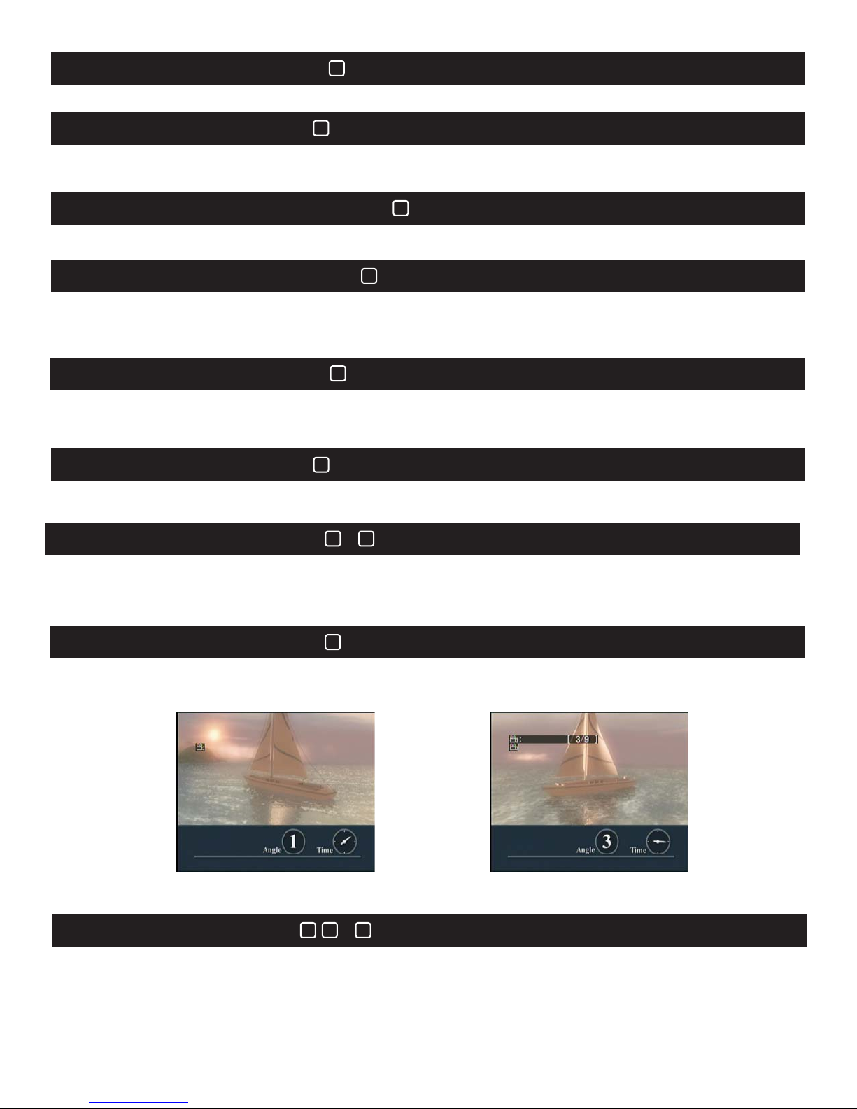
42
Volume Up &DownVolume Up &Down
The Music Volume Control buttons (42) allow the user to adjust the playback volume of the
53
Music Volume ControlMusic Volume Control
The control is set to adjust the built-in amplifier volume. It produces no effect on AUX audio output.
The control is set to adjust the built-in amplifier volume. It produces no effect on AUX audio output.
Note: Before output audio to external speaker or amplifier, turn the volume to minimum.the
Note:
Before output audio to external speaker or amplifier, turn the volume to minimum.the
2
Mute
Press to mute the audio. Press again to cancel.Press to mute the audio. Press again to cancel.
26
Menu ModeMenu Mode
The Menu Mode (26) allows the user to bring up the main menu of a DVD disc. Once the DVD
disc's main menu is displayed, use the directional arrows (24) to navigate to the desired menu
item. Pressing the Enter (25) or the Play (29) button selects the chosen menu item.
20
VCD Menu (PBC)VCD Menu (PBC)
The PBC (Playback Control) button (20) is used with VCD discs exclusively. Pressing the PBC
button with a VCD inserted will bring up the VCD disc's main menu. Use the Numeric Kaypad (12)
to select the desired VCD scene. Confirm the selection by pressing the Enter button (25).
40
Exit VCD Menu (PBC)Exit VCD Menu (PBC)
When PBC is on, press this button for returning to the menu during playback.
When PBC is on, press this button for returning to the menu during playback.
function works on VCD disc only.
This function works on VCD disc only.
This
22
21
Title & SubtitleTitle & Subtitle
&
Pressing the Title button (22) brings up the title menu on a DVD disc.
Pressing the Subtitle button (21) brings up the subtitle display on DVD discs allowing that option.
19
Change Angle PlayChange Angle Play
When playing a DVD disc that incorporates multi-angel playback, the Angle button (19) allows
switching between the video angels.
Angle 1Angle 1
Angle 3Angle 3
Pressing the Play button (29) starts playback of the currently playing disc. Pressing the Pause
button (28) pauses the playback of the currently playing disc. Pressing the Stop button (30)
stops playback of the currently playing disc.
30
2829
Play, Pause & StopPlay, Pause & Stop
&
25
Page 26
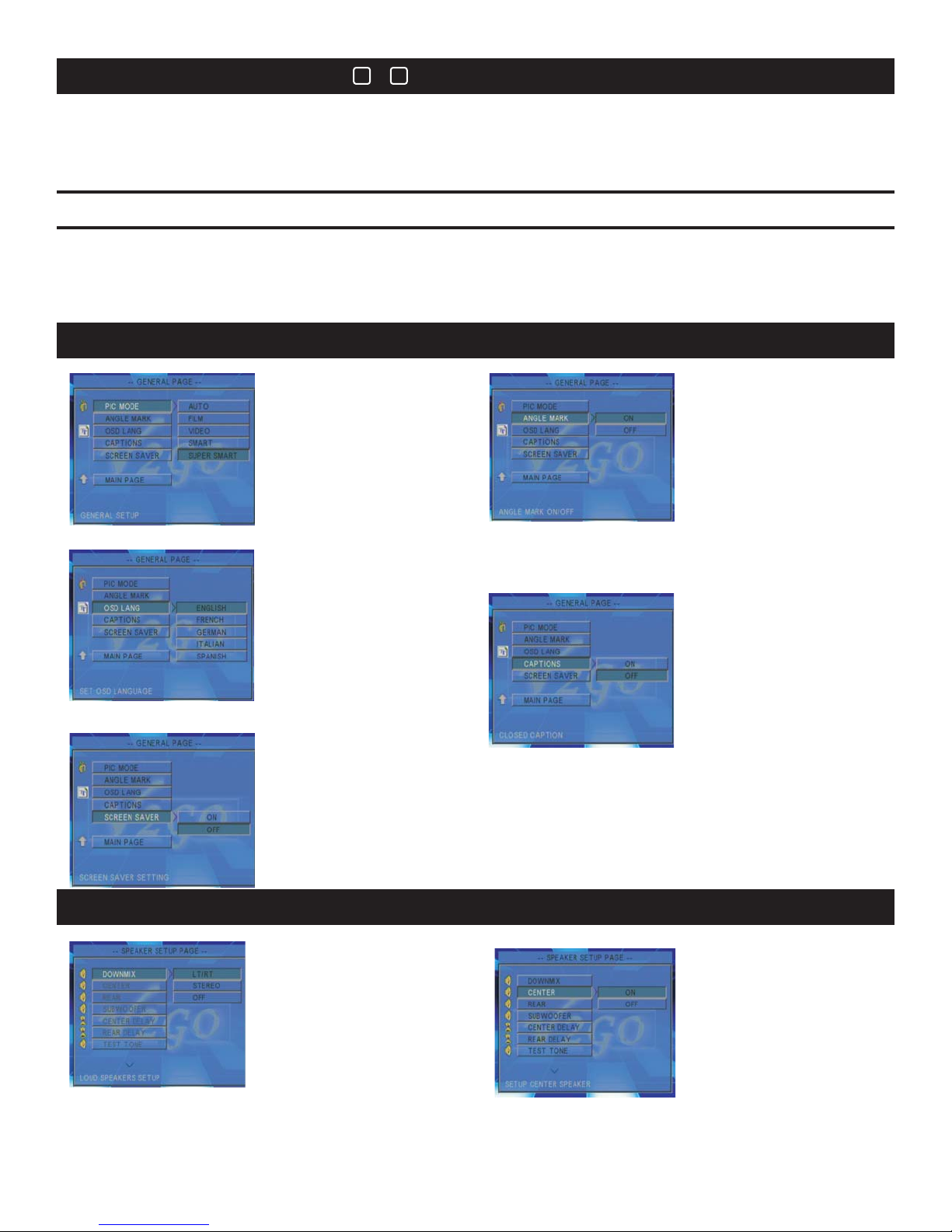
18
19
MIC knob
MIC knob
To raise or lower the volume of MIC 1 and MIC 2.
To
raise or lower the volume of MIC 1 and MIC 2.
ECHO knob
ECHO knob
To raise or lower the reverb level of microphones.
raise or lower the reverb level of microphones.
To
Karaoke Tune UpKaraoke Tune Up
&
SETUP
Stop any playback. Press Setup button (23) to enter the Setup menu.
Use the Directional Arrow buttons (24) and Enter (25) button to select the desired operation.
To exit Setup, press Setup button or choose the Exit Setup option on the attached video display.
General SetupGeneral Setup
1.PIC MODE1.PIC MODE
Use to set the picture mode.
3.OSD LANGUAGE
3.OSD LANGUAGE
Use to select your screen
display language.
5.SCREEN SAVER5.SCREEN SAVER
UsetosettheScreenSaverOnorOFF. When
set to ON the screen saver will start if theGO-210
has been inactive for an extended period of time.
The screen saver will not automatically start if
OFF has been selected.
2.ANGLE MARK2.ANGLE MARK
Use to display the
multi-angel mark when
playing multi-angle
DVD discs.
When set to ON, the
Angel Mark will display
when multi-angels are
available. When set to
OFF, no multi-angel
mark will be displayed.
4.CAPTIONS
SettoONtoshow
captions and OFF to hide
them.
1.DOWNMIX
Two audio channels will be
available when LT/RT or
STEREO is selected. When
set to 5.1 CH mode, 6 audio
channels (surround sound)
will be available.
Speaker SetupSpeaker Setup
2.CENTER
Select ON to enable
output from center
speaker. Select OFF
when standard stereo has
been selected.
26
Page 27
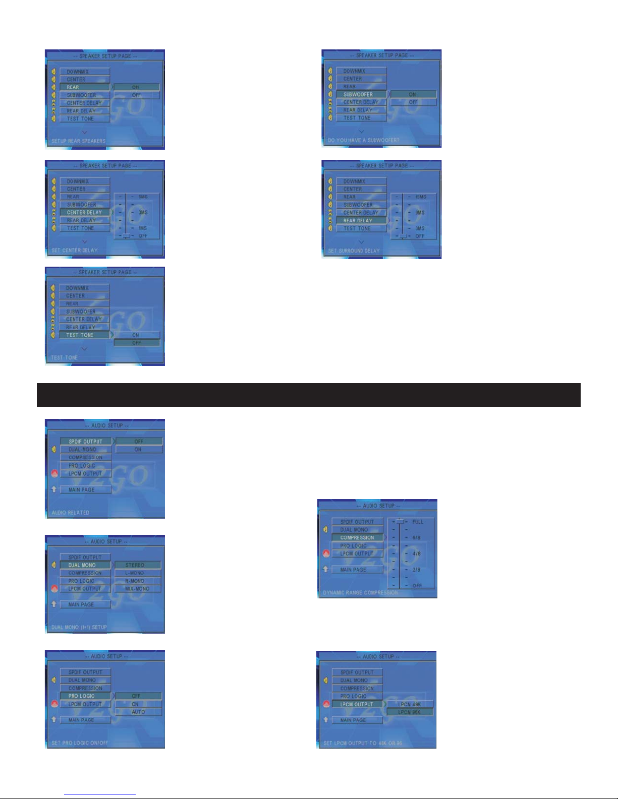
3.REAR
Select ON to enable left
surround (SL) and right
surround (SR) channels.
Select OFF when standard
stereo has been selected.
4.SUBWOOFER
Select ON to enable
subwoofer speaker
output. Select OFF
when standard stereo
has been selected.
5.CENTER DELAY5.CENTER DELAY
Use to select the delay time of
the center signal output.
7.TEST TONE
7.TEST TONE
In the 5.1 CH mode (surround sound) the Test Tone is used to test each of the
connected speakers. The left corner of the connected video monitor will
graphically display each speaker as it is sequentially tested. Select OFF to end
the test.
6.REAR DELAY6.REAR DELAY
Use to select the delay
time of the SL/SR
output to match the
placement of the center
speaker.
Audio SetupAudio Setup
1.SPDIF OUTPUT1.SPDIF OUTPUT
This sets the optical and coaxial digital outputs to ON or OFF.
Set to OFF if no digital or optical devices are connected.
Set to SPDIF/RAW when connected to an amplifier with Dolby decoding.
Set to SPDIF/PCM when using a stereo amplifier to play Dolby digital discs.
2. DUAL MONO2. DUAL MONO
Use to select STEREO
OUTPUT, L-MONO output,
R-MONO output or MIXMONO output. MIX-MONO
results in a mono audio
signal sent to both the R
and L speakers.
4.PRO LOGIC4.PRO LOGIC
Use to turn the built-in
Dolby decoder ON or OFF.
The AUTO setting
automatically selects the
disc format.
27
3.COMPRESSION
Use to control acoustic
highs and loud portions
of an audio track
(example: a war movie
with bombs exploding
and then with people
whispering in the next
scene). This control
dynamically lowers the
volume and still keeps
the original quality of the
audio track.
5.LPCM OUTPUT
5.LPCM OUTPUT
Use to select personal
preferences of audio
timbre.
Page 28
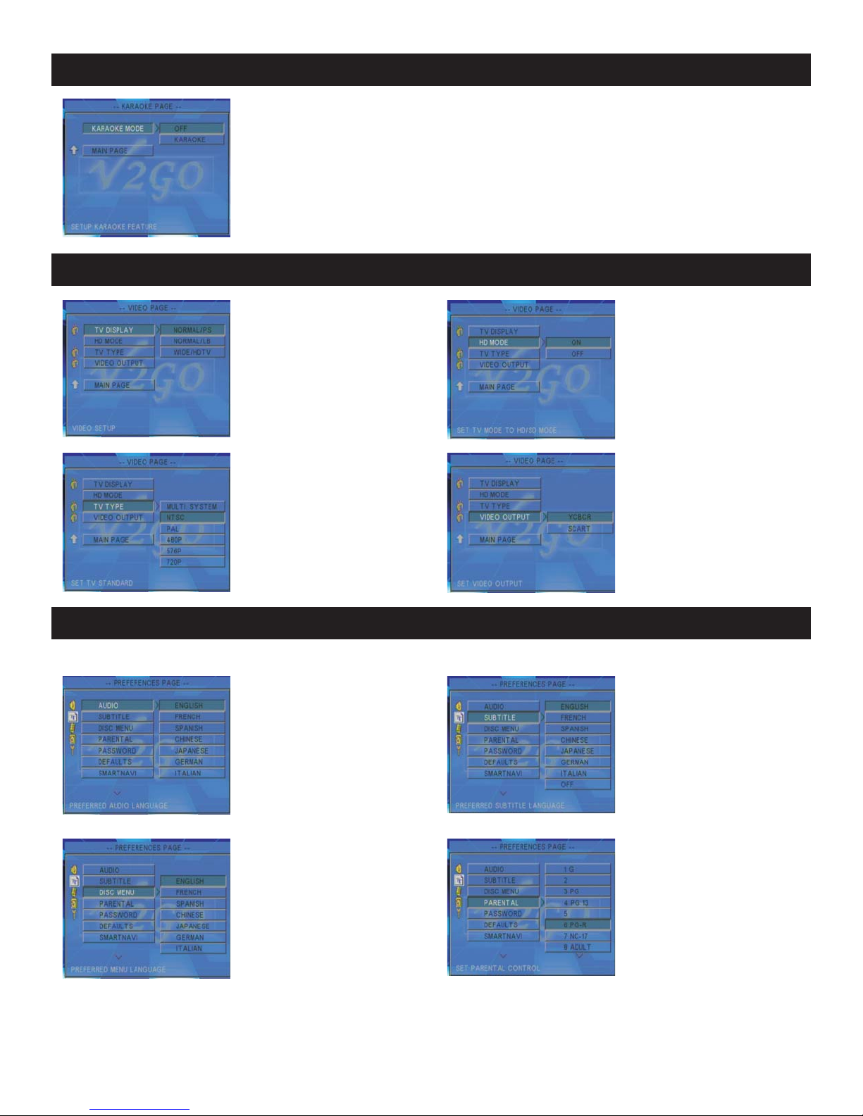
Karaoke SetupKaraoke Setup
1.KARAOKE MODE1.KARAOKE MODE
Select ON to enter the karaoke mode. Key control function is only
available with the KARAOKE mode turned on. Select OFF to turn off the
karaoke mode. When 5.1 CH is selected the KARAOKE mode is set to
OFF automatically.
Video SetupVideo Setup
1.TV DISPLAY1.TV DISPLAY
Use the TV DISPLAY to
choose the TV display mode
for video output.
3.TV TYPE3.TV TYPE
Set the video output that
matches your television's
system format.
Stop playing before entering setup.Stop playing before entering setup.
1.AUDIO 2.SUBTITLE
Use to select language for
discs with multi-language
capabilities.
2. HD MODE2. HD MODE
Turn ON to enable the
HD mode.
Turn OFF to disable the
HD mode.
4.VIDEO OUTPUT4.VIDEO OUTPUT
Select the video output
connection type.
Preferences SetupPreferences Setup
Use to select your
preferred subtitle
language.
3. DISC MENU3. DISC MENU
Use to select the disc
language.
4.PARENTAL
Allows the user to set
passwords for each
rating of DVD discs – G,
PG,PG-13,RandX
ratings are supported.
Theusermustentera
password before
changing the level of
control.
28
Page 29
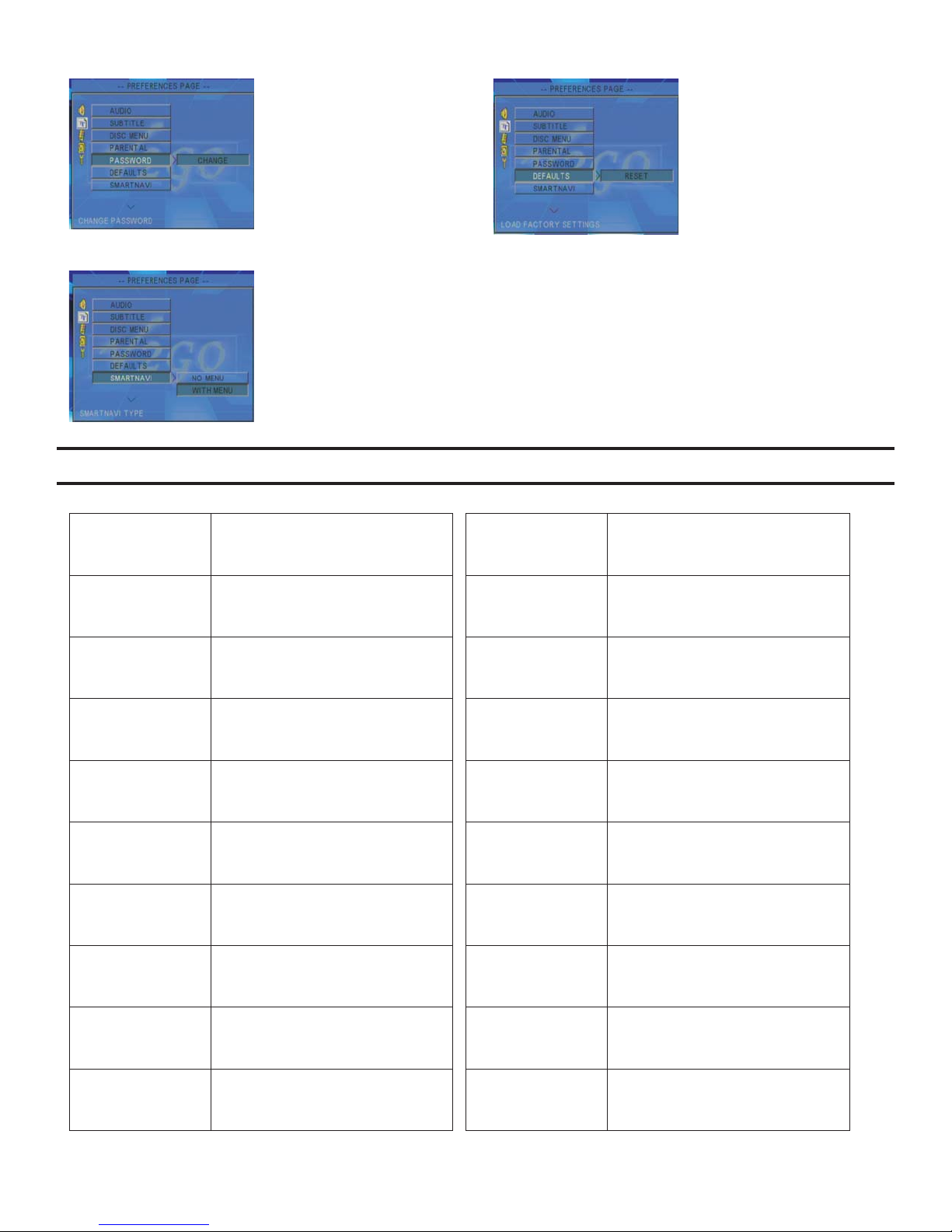
ModelNO.
5.PASSWORD
The user may change the
password with this option.
The existing password is
required before changes are
allowed. In the event the
password has been
forgotten, enter 3308 to
reset the system.
7.SMART NAVI7.SMART NAVI
Use to enable MP3 discs to
play as if they were standard
CD discs.
SPECIFICATIONS
GO-210
Audio
Audio
output
output format
format
6.DEFAULTS
Use to reset the
GO-210's preferences
to the original factory
presets.
Stereo,5.1CH,
Stereo,5.1CH,
optical,coaxial
optical,coaxial
Power
Power
requirements
requirements
Power
Power
consumption
consumption
Readable
Readable
discs
discs
Discs size
Discs size
requirements
requirements
Video format
Video format
Video
Video
output type
output
output level
output
type
Video
Video
level
Audio outAudio out
100V/240VAC,50/60HZ
120W
DVD,MPEG-4,VCD1.0-3.0,
DVD,MPEG-4,VCD1.0-3.0,
MP3,CD+G,CD,JPEG,WMA,
MP3,CD+G,CD,JPEG,WMA,
CD-R/RW,DVD+R/-R/RW
CD-R/RW,DVD+R/-R/RW
Diameter:120mm/80mmDiameter:120mm/80mm
NTS,PAL,AUTO
VIDEO,S-VIDE0
VIDEO,S-VIDE0
VGA,SCART,YUV RGB,
VGA,SCART,YUV RGB,
CVBS: 1Vp-p 75ohmCVBS: 1Vp-p 75ohm
20W+20W/6ΩRMS
DVD frequency
DVD frequency
response
response
DVD S/N ratioDVD S/N ratio
DVD harmonic
DVD harmonic
distortion
distortion
Karaoke
Karaoke
frequency
frequency
response
response
Karaoke
Karaoke
S/N
S/N ratio
ratio
Echo levelEcho level
Total harmonic
Total harmonic
distortion
distortion
Dimensions
Dimensions
(L)*(W)*(H)
(L)*(W)*(H)
20Hz-20KHZ
80dB
0.3%0.3%
20-20KHZ
70dB
10 levels10 levels
0.5%0.5%
510mm*330mm*360mm
510mm*330mm*360mm
(20"x13"x14.2")
(20"x13"x14.2")
Remote distanceRemote distance
Max 7 meters/30 angleMax 7 meters/30 angle
29
Weight
20.2kg(44.88lbs)
Page 30
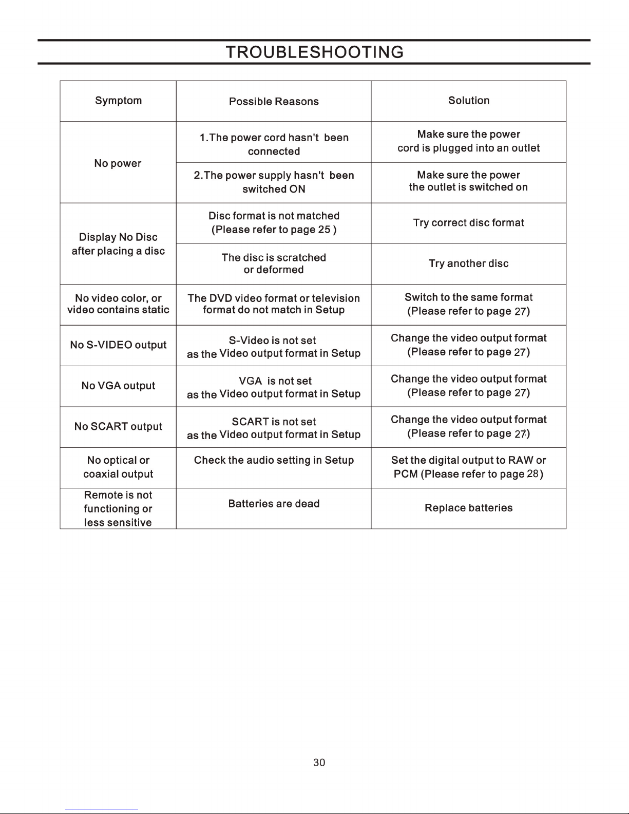
Page 31

Note:
BBE and its designs are the registered trade marks of BBE Sound Incorporated, registered in the
U.S. and other countries.
9528 Rush St#I South El Monte
CA, 91733
Tel: 626 5828098
Fax: 626 5828908
Toll free: 1-877-566V2GO(5668246)
31
 Loading...