

Page 1
R
Dyna-Mic.01
2.4GHz Digital Wireless Microphone2.4GHz Digital Wireless Microphone
w/ Adaptive Frequency Hopping Technology
Your new V2GO Dyna-Mic.01 is most technologically advanced
Your new V2GO Dyna-Mic.01 is most technologically advanced
wireless microphone system available. Th wireless system has been
wireless microphone system available. Th wireless system has been
designed using 2.4GHz Adaptive Frequency Hopping Technology (AFHT),
designed using 2.4GHz Adaptive Frequency Hopping Technology (AFHT),
leading digital wireless transmission solution in the world.
the leading digital wireless transmission solution in the world.
the
This technology goes beyond the inherent restriction of traditional FM, VHF
This technology goes beyond the inherent restriction of traditional FM, VHF
or UHF wireless microphone systems such as narrow frequency response
or UHF wireless microphone systems such as narrow frequency response
and weak interference rejection, while still completely covering the full audio
and weak interference rejection, while still completely covering the full audio
spectrum (20Hz to 20KHz). AFHT offers the advantages of extraordinarily
spectrum (20Hz to 20KHz). AFHT offers the advantages of extraordinarily
strong interference rejection, the lowest power consumption of any wireless
strong interference rejection, the lowest power consumption of any wireless
microphone system available and easy installation and operation. The AFHT
microphone system available and easy installation and operation. The AFHT
design is creating a revolution in wireless systems, led by V2GO
design is creating a revolution in wireless systems, led by V2GO
Technologies,
Technologies, Inc.
The Dyna-Mic.01 wireless microphone system is able to deliver superior
The Dyna-Mic.01 wireless microphone system is able to deliver superior
wireless vocal or music transmission without distortion or overload. It has
wireless vocal or music transmission without distortion or overload. It has
been designed for use in indoor spaces up to 8,000 sq.ft. without dropout or
been designed for use in indoor spaces up to 8,000 sq.ft. without dropout or
audio fading. Depending on specific conditions, the range of the
audio
Dyna-Mic.01 may be farther in outdoor applications. Its near perfect audio
Dyna-Mic.01 may be farther in outdoor applications. Its near perfect audio
reproduction is making the Dyna-Mic.01 the preferred microphone system
reproduction is making the Dyna-Mic.01 the preferred microphone system
for professional musicians, disc jockeys, karaoke jockeys,
for
professional musicians, disc jockeys, karaoke jockeys,
and home singing enthusiasts.
and
home singing enthusiasts.
Inc.
fading. Depending on specific conditions, the range of the
one of the
one of the
is
is
FEATURES:
FEATURES:
1. Audio frequency response: 20 Hz to 20 KHz 1.5dB - streaming CD audio
1. Audio frequency response: 20 Hz to 20 KHz 1.5dB - streaming CD audio
quality
quality
2. Leading edge Adaptive Frequency Hopping Technology (AFHT at
2. Leading edge Adaptive Frequency Hopping Technology (AFHT at
2.4GHz/4mbps) digital wireless transmission and reception
2.4GHz/4mbps) digital wireless transmission and reception
3. Adaptive frequency hopping: 21 globally assigned public channels
3. Adaptive frequency hopping: 21 globally assigned public channels
resulting in extraordinarily high interference rejection
resulting in extraordinarily high interference rejection
4. Extremely low power consumption: Up to 25 hours continuous operation
4. Extremely low power consumption: Up to 25 hours continuous operation
on 2 alkaline batteries
on 2 alkaline batteries
5. Long range: 60 feet indoors / 180 feet outdoors effective
5. Long range: 60 feet indoors / 180 feet outdoors effective
transmission distance under normal conditions
transmission distance under normal conditions
6. Low Noise : <0.5mV
6. Low Noise : <0.5mV
7. Highly sensitive dynamic microphone
7. Highly sensitive dynamic microphone
(Mic)
(Mic)
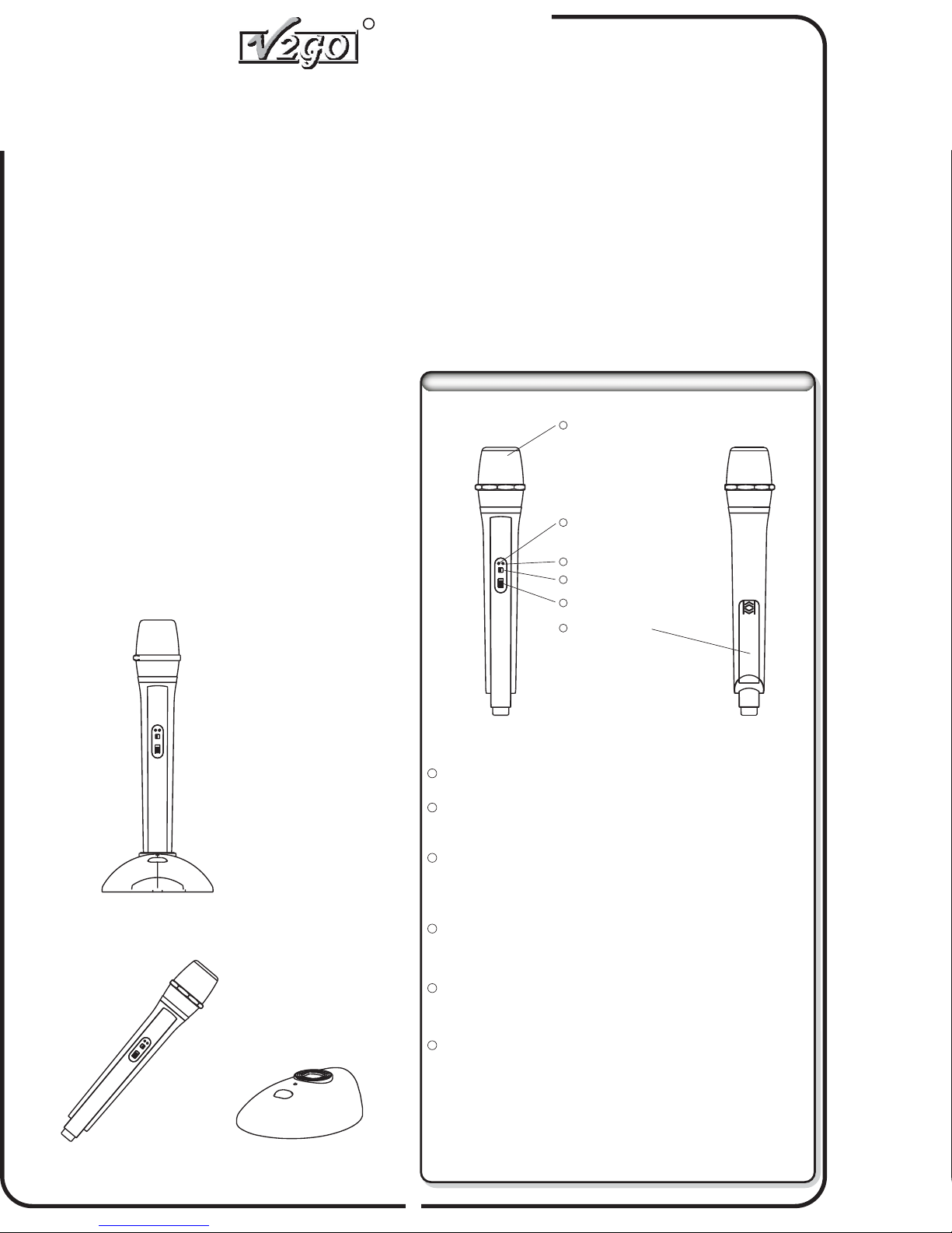
HANDHELD MICROPHONE (TRANSMITTER)HANDHELD MICROPHONE (TRANSMITTER)
Cardioid unidirectionalmicrophone pickup
1
Power Indicator(Red)
2
Signal Indicator(Green)
3
4
Power Switch
5
Mute switch
Battery cover
6
Handheld Microphone(Transmitter) Receiver Base(Receiver)
1
Cardioid unidirectional microphone pickup The pickup converts voice or music to electronic signals.
2
Power indicator (red) The red power indicator illuminates when the microphone's
batteries are low.
3
Signal indicator (green) The green signal indicator illuminates and flashes once
communications are established between the wireless
microphone and the receiver/base.
4
Power switch -
Moving the switch to the left position turns the power off while
moving the switch to the right turns the power on.
5
Mute switch -
Moving the mute switch down mutes the microphone while moving
the switch up allows for transmission of voice or music.
6
Battery cover -
Pressing lightly on the raised surface while sliding the cover
towards the bottom of the microphone reveals the battery
compartment. The handheld microphone operates on 2 AA
batteries. Insert batteries with the positive (+) (raised button end)
pointing to the top of the microphone.
1
Page 2
7
Microphone StorageDock
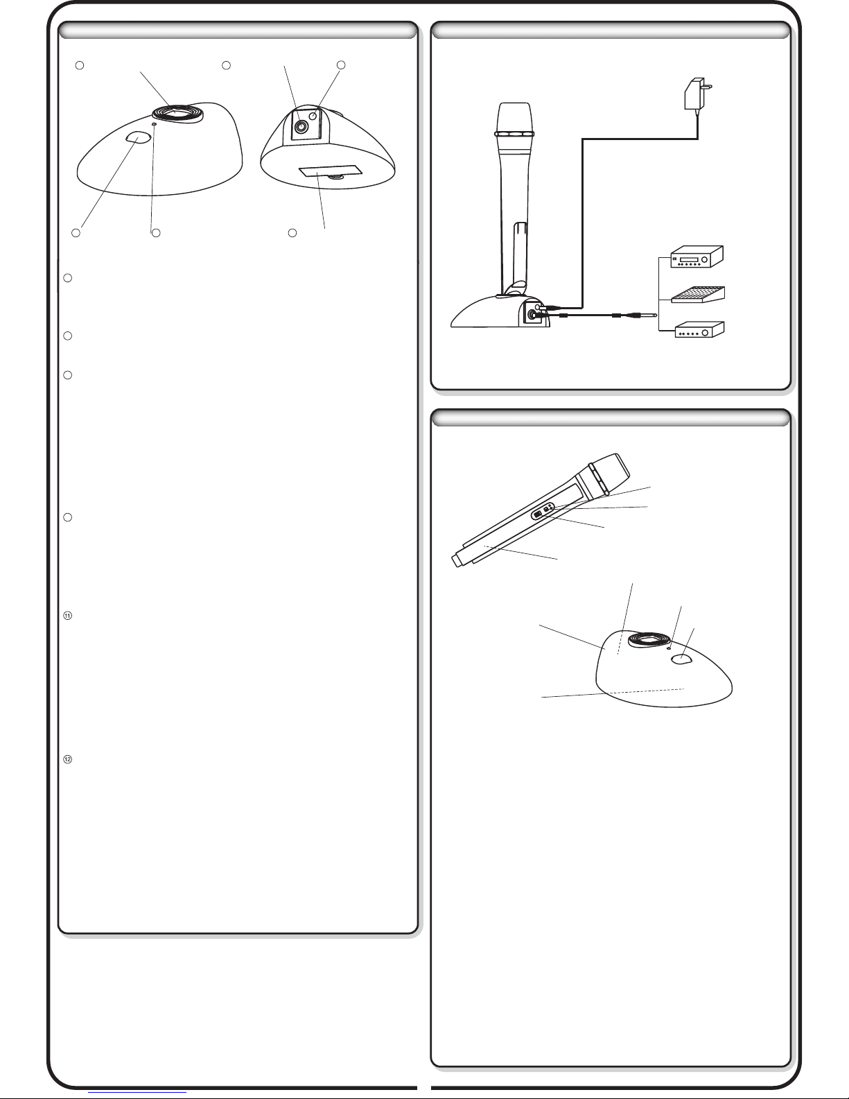
RECEIVER BASE (RECEIVER)RECEIVER BASE (RECEIVER)
11
Audio Output
12
Ac Adapter Jack
SETUP ILLUSTRATION
AC110V
/AC220V
8
Power Switch
7
Microphone storage dock -
9
Power andSignal Indicator
10
Battery CompartmentCover
The Microphone docking opening allows for the convenient
storage of the microphone in the base when the microphone is not
in use.
8
Power switch -
Pressing the power switch turns the receiver base on or off.
9
Power and signal indicator Once the receiver base is powered on, the LED will illuminate red.
Once the handheld microphone is turned on, the green LEDs on
both the handheld microphone and the receiver base will flash in
sequence indicating the two devices are communicating. The red
LED will illuminate when the receiver base's batteries need
replacement. A constant weak red LED indicates that the base's
batteries are low and in need of replacement. The red LED will not
illuminate if the base is powered by theAC power adaptor.
10
Battery compartment cover To open the battery compartment on the receiver base, gently
press the “D” shaped tab on the compartment cover toward the
compartment and then gently lift the compartment cover off. The
receiver base operates on (2) AAA alkaline batteries. Optionally,
the base may be powered from an AC adaptor (see 12)
Audio output Your V2GO Dyna-Mic has been supplied with an audio connection
cable. The small end of the cable connects to the receiver base as
shown. Note that the connector has a polarization tab that must
align with the slot in the receiver base's connector. To remove,
depress the small black button and gently pull the connector out.
The other end of the supplied audio cable (standard TR ¼” audio
connector) connects to any ¼” microphone input on your PA
System, karaoke player, audio mixer or stereo system.
AC adapter jack -
For use with the 9VDC, 160mA,AC adaptor. When the AC adaptor
is used, the receiver base's batteries will be internally
disconnected.
(Note: The use of the AC adaptor will not recharge batteries
(Note:
installed in the receiver base. Insert the end of the AC adaptor's
power cable firmly into the AC power connector.)
Amplifier
PASystem
Audio Mixer
SETUP INSTRUCTION
Illuminating greensignal indicator
Power switchis on theright
Mute switchis up
Batteries areinstalled
Hook upwith audio system
Illuminating green
AC Adaptoris connected
Or batteriesare installed
1. Insert batteries in handheld microphone. See 6
2. Insert batteries in receiver base. See 10
3. Connect AC adaptor, then plug the AC adaptor into a power outlet.
See 12
4. Connect supplied cable between the Dyna-Mic.01 and your audio
system. See 11
5. Depress the power button on the receiver base. See 9
6. Switch the power switch on the handheld microphone to the ON
position. See 4
7. Set audio level (microphone input level) initially to the ½ way
position on the attached karaoke player, audio mixer or PA
system.
8. With the audio system that the Dyna-Mic.01 is connected to
powered on and operating, switch the handheld microphone's
mute switch to the UP (un-muted) position.
Press onceto power on
9. Speak into the microphone to verify operation and to adjust the
microphone's sound level on the attached karaoke player, audio
mixer or PA system.
2
Page 3
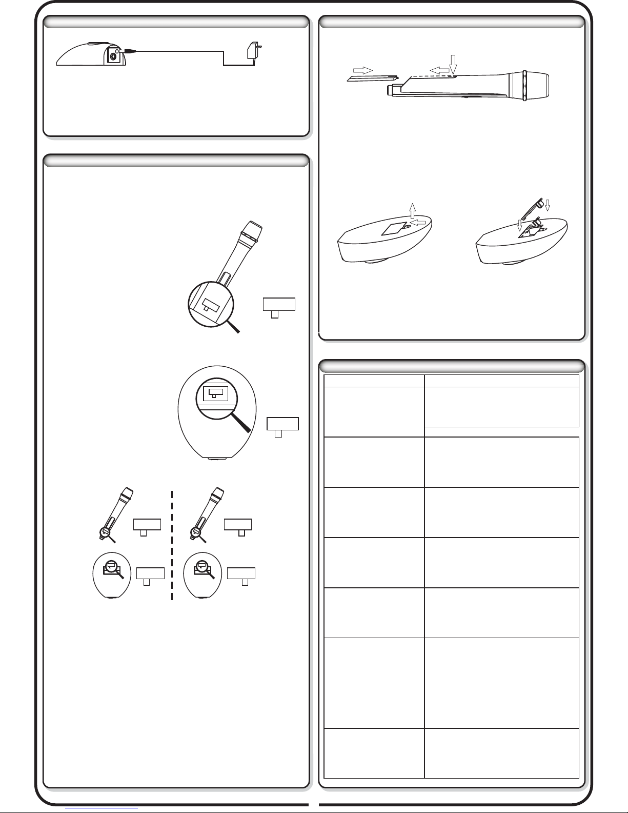
POWER ADAPTER CONNECTIONPOWER ADAPTER CONNECTION
1 A Universal AC power adapter; (AC110V / AC220 input, DC9V.
2 Plug the DC end into adapter jack of receiver base.. firmly
3 Notice: Remove batteries if use AC adapter for extended period..
AC110V
/AC220V
BATTERY CHANGE
1 Push down the case cover ’s forepart slightly and slide backward
.
to open;
Using 2 Dyna-Mic.01 Wireless Systems at OnceUsing 2 Dyna-Mic.01 Wireless Systems at Once
The V2GO Dyna-Mic.01 system can be operated simultaneously
with a second V2GO Dyna-Mic.01 system. To avoid having
the 2 systems interfere with one another, they must be assigned
different frequencies. This is accomplished as follows:
1. Open the battery compartments on both
of the wireless microphones and both of
the receiver bases.
2. Remove the batteries from both of
the receiver bases.
3. Locate the micro switch in the
battery compartment of the
receiver base. It is a silver
rectangular box approximately
5/16 inch wide and 1/4 inch high.
A black tab protrudes from the side of the micro switch.
4.Using a pencil or toothpick,
move the black tab in one
receiver base to A position,
and the other receiver base to
the B position. You have now
designated one receiver base
as System A and the other as
System B.
A
A
B
AB
AB
AB
5. Locate the micro switch on each handheld microphone. The
batteries do not need to be removed in the handheld wireless
microphone. The micro switch is located just below the batteries.
6. Using a pencil or toothpick, move the black tab in one handheld
wireless microphone A position, and the other handheld wireless
microphone to B position. You have now designated one
handheld wireless microphone as System A and the other as
System B.
B
AB
AB
A
B
AB
A
AB
AB
AB
B
2 Place 2 AA new batteries as instructed on compartment label;.
3 Close up the cover..
1 Tip up to open the cover;.
2 Place new (2) AAA batteries as instructed on compartment label;.
3 Close up the cover..
TROUBLESHOOTING
Problem
Red and/or green LEDs
do not illuminate
Green LEDs do not flash
in unison
All LEDs operate
correctly but no sound is
heard from karaoke
player, audio mixer or PA
system
Interference is
introduced into the
sound system whenever
the Dyna-Mic.01 is
turned on
While in operation the
Dyna-Mic.01
occasionally “drops out”
Hear Static
Solution
1. Batteries are dead, or are not
installed correctly
2. Power switch(s) are not turned on
1. Wireless microphone is too far from
the receiver base
2. In a dual microphone setup, the
micro switches may not be set
correctly. See instructions for using
2 microphones.
1. Check that the supplied audio cable is
connected correctly
2. Make sure that the mute switch is not in
the mute position
3. Double check all settings on karaoke
player, audio mixer or PAsystem
Move the Dyna-Mic.01's receiver base
away from interference causing
electronic devices such as television
monitors or devices containing electric
motors
Move the handheld microphone closer
to the receiver base. See instructions
for ideal operating range.
1.Move microphone further from
receiver base. Keep them at least
2 feet distance apart.
2.Keep 2 handhold microphones at
least 2 feet distance apart.
3.Take out the microphone’s
batteries and reinstall them to
reset the system.
7. Reinsert all batteries paying close attention to each batteries
polarity. Handheld wireless microphone System A will now
communicate with receiver base System A.
8. Handheld wireless microphone System B will now communicate
with receiver base System B.
Other unlisted problem
3
1.Reset the system by reinstalling
batteries
2.Go to www.v2gotech.com for further
information or call 1-877-566-8246 for
more assistance.
Page 4
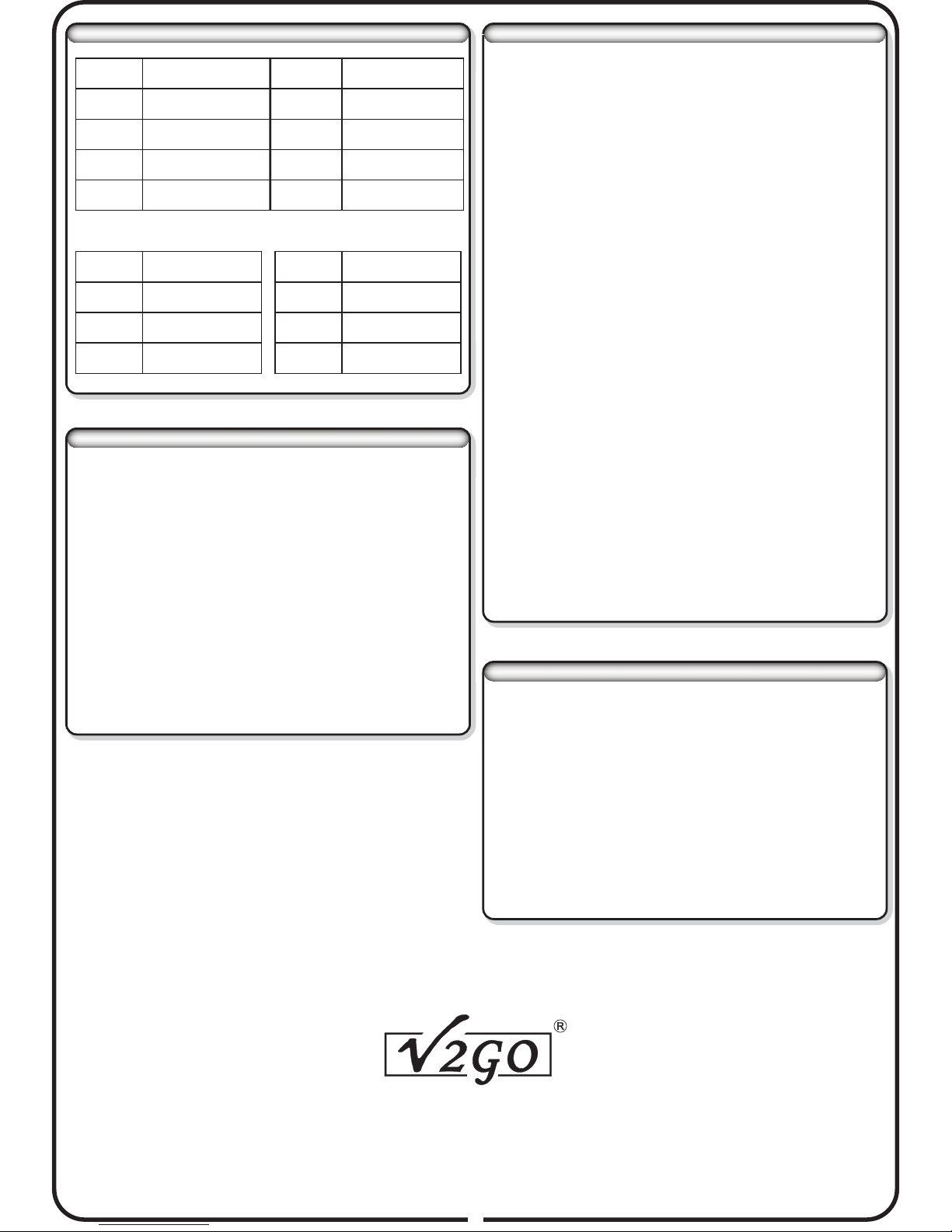
SPECIFICATIONS
MICROPHONE MAINTENANCE AND USAGE TIPSMICROPHONE MAINTENANCE AND USAGE TIPS
Operating
Frequency
Frequency
Response
Noise
Output
Level
Package
Size
2.4GHz--2.483GHz
20Hz~20KHz/ 1.5dB
<0.5mV
10mV( 0mV Input)1
350mmX260mmX85mm
Handheld wireless microphone
Dimension
Net Weight
Power
Supply
Working
hours
50mmX50mmX260mm
0.38KG
2xAA 1.5V alkaline
batteries
>=25hrs
Effective
Distance
Sampling
Rate
Operating
temperature
Transmitter
power
Gross
Weight
Receiver Base
Dimension
Net Weight
Power
Supply
Working
hours
Indoor: 20M
Outdoor 60M:
44.1KHz/16bit
0~50℃+ ℃
Average 17dB/50mW
1.5KG
115mmX140mmX40mm
0.26KG
2x AAA 1.5V alkaline
batteries or DC 9V 160mA
>=25hrs
ELECTRONIC INTERFERENCE ISSUES:ELECTRONIC INTERFERENCE ISSUES:
The V2GO Dyna-Mic.01 may cause disturbance of wireless signals
in some locations. Neither V2GO Technologies, Inc, nor its dealer
network can guarantee wireless microphone systems will not
produce interference with radio, television or wireless telephone
systems. If interference is apparent, the following tips may reduce
interference:
1. Reset the system by turning power off on all components for 30
seconds and then repower the system.
2. Reposition the microphone and receiver further from other
electronic devices such as televisions and radios.
3. Contact the manufacturer of the device being interfered with for
technical support.
Patent(s) pending
Patent(s) pending
Copyright 2007 V2GO Technology Corp.
Copyright
Rev.
Rev. DM01-051707-2
All
All Rights Reserved
2007 V2GO Technology Corp.
DM01-051707-2
Rights Reserved
Your V2GO Dyna-Mic.01 is a sensitive instrument. Avoid:
1. Dropping or hitting the microphone
2. High levels of humidity or moisture
3. Temperatures over 120 degrees Fahrenheit
4. Blowing into the microphone
5. Slapping the microphone to see if it is operating
Clean your V2GO Dyna-Mic.01 with a clean cloth slightly moistened
with water. Do not ever use any petroleum product to clean your
system.
Periodically unscrew the metal mesh from the end of your handheld
wireless microphone. Inside the metal mesh cover you will find a
black sponge material. Carefully remove the black sponge and
gently hand wash it in cold water with a small amount of soap. Rinse
the black sponge and allow it to dry completely before reassembly.
The use of a foam cover over the steel mesh of the microphone is not
normally needed. In some cases the foam cover will muffle the voice
and degrade the overall audio quality. However, when using the
V2GO Dyna-Mic.01 outdoors on a breezy day, a foam windscreen is
recommended.
Envision the steel mesh of your handheld wireless microphone as an
“eye ball”. If this “eye ball” can see (or otherwise points at) a
speaker, feedback is likely. Whenever possible, position the singer
either facing the speaker(s) or slightly behind the speaker(s).
All microphones work best when the singer is singing directly into
the very end of the steel mesh of the microphone, not the side.
Remember, a microphone is not magic - when using a microphone,
sing loudly. A microphone is unable to create a pleasant tone from a
whisper.
INCLUDED ACCESSORIES
1. Dyna-Mic.01 Handheld Microphone1. Dyna-Mic.01 Handheld Microphone
2 Dyna-Mic.01 Receiver Base.
2 Dyna-Mic.01 Receiver Base.
3. Dyna-Mic.01 Power Adapter3. Dyna-Mic.01 Power Adapter
4. Audio output cable4. Audio output cable
5. AA battery
6. System A Labels
6. System A Labels
7. System B Labels7. System B Labels
8. User’s manual8. User’s manual
9. Warranty Card9. Warranty Card
10. Portable anti-shock PET package10. Portable anti-shock PET package
(1)
(1)
(1)
(1)
(2)
(4)
(4)
(4)
(1)
(1)
(1)
V2GO Technology Corp.V2GO Technology Corp.
California, U.S.ACalifornia, U.S.A
www.v2gotech.com
4
 Loading...