

Page 1
V2 S.p.A.
Corso Principi di Piemonte, 65/67
12035 RACCONIGI (CN) ITALY
tel. +39.0172.812411 - fax +39.0172.84050
info@gatestore.co.uk www.remotecontrolgates.co.uk
Easy3-4
CENTRALE DI COMANDO ANALOGICA
PER SERRANDE AVVOLGIBILI
I
ANALOG CONTROL UNIT FOR ROLLER
SHUTTERS
GB
ARMOIRE DE COMMANDE ANALOGIQUE
POUR STORES
F
CUADRO DE MANIOBRAS ANALÓGICO
PARA PERSIANAS ENROLLABLES
E
QUADRO ELÉCTRICO ANALÓGICO PARA
ESTORES DE ENROLAR
P
ANALOGE STEUERUNG FÜR ROLLTORE
D
ANALOGE STUURCENTRALE VOOR
ROLLUIKEN
NL
IL n. 207
EDIZ. 20/10/2010
Page 2

Page 3
ENGLISH
17
INDEX
IMPORTANT REMARKS ........................................................................................................18
DECLARATION OF CONFORMITY ........................................................................................18
DESCRIPTION OF THE CONTROL UNIT..................................................................................19
TECHNICAL SPECIFICATIONS................................................................................................19
ELECTRIC CONNECTIONS TABLE ..........................................................................................20
OPTICAL EDGE INSTALLATION (EASY4 only) ........................................................................21
FIRE INPUT ..........................................................................................................................21
OPERATION WITH A TIMER ..................................................................................................22
CASE WITH KEYPAD ............................................................................................................22
CABLE GLAND ASSEMBLY....................................................................................................23
DISPLAYING THE SET FUNCTIONS ........................................................................................24
ALTERING THE FUNCTIONS ..................................................................................................25
FUNCTION TABLE ................................................................................................................26
ADJUSTING THE OPERATING TIME ......................................................................................28
ADJUSTING THE PAUSE TIME ..............................................................................................29
ADJUSTING THE COURTESY LIGHT OFF DELAY ....................................................................29
OPERATION WITH REMOTE CONTROL ................................................................................30
MEMORISING REMOTE CONTROL UNITS ............................................................................30
DISTANCE MEMORISING OF REMOTE CONTROL UNITS........................................................31
DELETING ALL THE REMOTE CONTROL UNITS......................................................................31
VISUALISATION AND SIGNALLING USING LED......................................................................32
Page 4

ENGLISH
18
IMPORTANT REMARKS
For any installation problem please contact our
Customer Service at the number +39-0172.812411
operating Monday to Friday from 8:30 to 12:30
and from 14:00 to 18:00.
V2 has the right to modify the product
without previous notice; it also declines any
responsibility to damage or injury to people or
things caused by improper use or wrong
installation.
Please read this instruction manual very
carefully before installing and programming
your control unit.
• This instruction manual is only for qualified
technicians, who specialize in installations and
automations.
• The contents of this instruction manual do not
concern the end user.
• Every programming and/or every maintenance
service should be done only by qualified
technicians.
AUTOMATION MUST BE IMPLEMENTED IN
COMPLIANCE WITH THE EUROPEAN
REGULATIONS IN FORCE:
EN 60204-1 (Machinery safety. electrical equipment
of machines, part 1: general rules)
EN 12445 (Safe use of automated locking
devices, test methods)
EN 12453 (Safe use of automated locking
devices, requirements)
• The installer must provide for a device
(es. magnetotermical switch) ensuring the
omnipolar sectioning of the equipment from the
power supply. The standards require a
separation of the contacts of at least 3 mm in
each pole (EN 60335-1).
• After making connections on the terminal
board, use one hose clamp to fix dangerous
voltage wires near the terminal board and
another hose clamp to fix safety low voltage
wires used for accessories connection; this way,
in case of accidental detachment of a
conducting wire, dangerous voltage parts will
not come into contact with safety low voltage
ones.
• The plastic case has an IP55 insulation; to
connect flexible or rigid pipes, use pipefittings
having the same insulation level.
• Installation requires mechanical and electrical
skills, therefore it shall be carried out by
qualified personnel only, who can issue the
Compliance Certificate concerning the whole
installation (EEC Machine Directive 89/392,
Annex IIA).
• The automated vehicular gates shall comply
with the following rules: EN 12453, EN 12445,
EN 12978 as well as any local rule in force.
• Also the automation upstream electric system
shall comply with the laws and rules in force
and be carried out workmanlike.
• The door thrust force adjustment shall be
measured by means of a proper tool and
adjusted according to the max. limits, which
EN 12453 allows.
• Connect the earthing lead of the motors to the
electricity grid earth system.
• Observe all necessary precautions (e.g. anti-static
bracelet) for handling parts sensitive to
electrostatic discharges.
DECLARATION OF CONFORMITY
V2 S.p.A. hereby declare that products (EASY3 EASY4) conform to the essential requirements
established in the following directives:
- 89/336/CEE (EMC Directive in accordance with
standards EN 61000-6-2, EN 61000-6-3 +
EN 50336)
- 2006/95/CEE (Low Voltage Directive in
accordance with standards EN 60335-1 +
EN 60335-2-103)
- 99/05/CEE (Radio Directive in accordance with
standard EN 301 489-3)
Racconigi, lì 28/01/2010
V2 S.p.A. legal representative.egale della V2 S.p.A.
Cosimo De Falco
Page 5

ENGLISH
19
DESCRIPTION OF THE CONTROL UNIT
The EASY digital control unit is an innovative V2
product that guarantees safety and reliability for the
automation of roller shutters.
• 230 Vac output for 1 single-phase motor
• 230 Vac output for flashing light or timed
courtesy light
• Input for key switch or pushbutton (START)
• Input for separate UP/DOWN commands
• Input for safety pushbutton (STOP)
• Input for safety photocell with automatic
operating test (PHOTO)
• Input for safety edge (mechanic or electronic)
with automatic operating test (EDGE)
• Input for fire emergency (FIRE)
• Monitoring the inputs using LED
• Operating logic and working times that can be
programmed using the programming key and
8 LEDs
• Possibility of operating in DEAD MAN mode
• Fitted 433.92 MHz radio receiver
• Possibility of saving 18 433.92 MHz
Personal Pass transmitters.
• Allows the total deletion of stored codes
EASY4
• Input for optical safety edge with 24V direct
current power supply and adjustment of the
power of the transmitter.
WARNING: use only FEEL optical safety
edges (see V2 catalogue)
TECHNICAL SPECIFICATIONS
230V models 120V models
Power supply 230V / 50Hz 120V / 60Hz
Max motor load 1100W 600W
Max accessories load 24V 3W 3W
Working temperature -20 ÷ +60 °C -20 ÷ +60 °C
Protection fuse F1 = 5A delayed F1 = 5A delayed
Dimensions 170 x 185 x 70 mm
Weight 800 g
Protection IP55
Page 6
ENGLISH
20
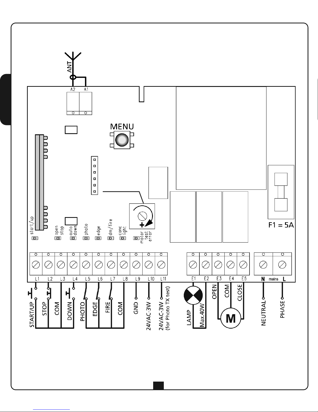
ELECTRIC CONNECTIONS TABLE
WARNING: Normally closed inputs STOP (L2), PHOTOCELL (L5), EDGE (L6), FIRE (L7), if not
used must be bridged through the COMMON terminal (-)
WARNING: a wrong connection of the antenna compromises seriously the RADIO working of
the control unit.
EASY4 only
Page 7
ENGLISH
21
OPTICAL EDGE INSTALLATION
(EASY4 only)
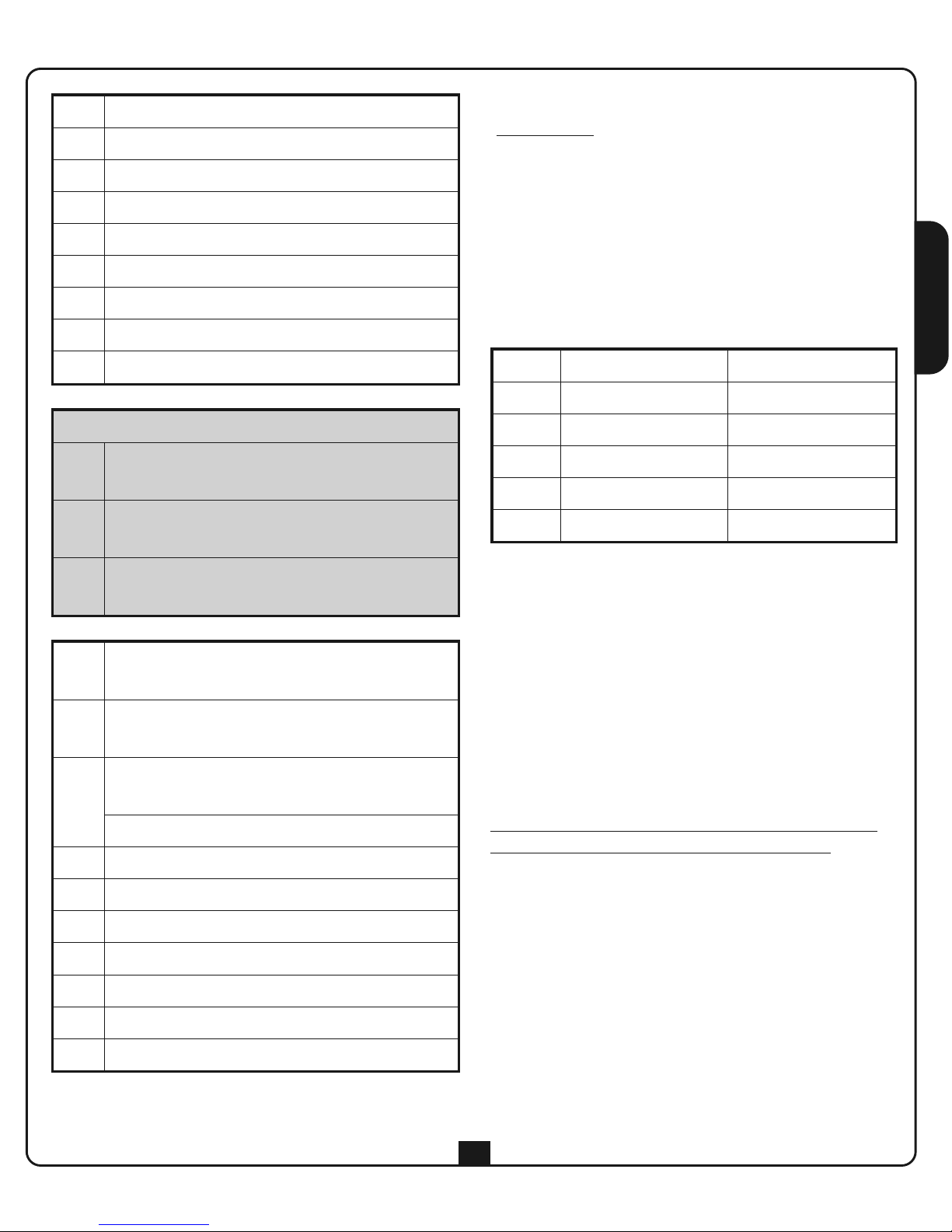
The EASY4 main control unit is configured for the
installation of one 24 Vdc powered optical edge
and transmitter power regulation.
PLEASE NOTE: only use FEEL optical edges
(please refer to the V2 catalogue).
Connect the transmitter and receiver in accordance
with the following table.
After having made the connections, power-up the
main control unit and adjust the power using the
trimmer located on the control unit so as to obtain
optimal edge operation.
FIRE INPUT
Safety input for connecting a fire or other type of
alarm requiring the immediate automatic opening
of the door.
The FIRE command should be connected between
the FIRE (L7) and COMMON (L8) terminals.
When the FIRE contact is opened, the door is
opened and cannot be closed again until the
contact is reset.
TRANSMITTER RECEIVER
L6 BLACK CABLE
L8 BLUE CABLE BLUE CABLE
L9 BLACK CABLE
L10 BROWN CABLE
L11 BROWN CABLE
L1
START/UP. N.O. contact
L2
STOP. N.C. contact
L3
COMMON (-)
L4
DOWN. N.O. contact
L5
PHOTOCELL. N.C. contact
L6
EDGE. N.C. contact
L7
FIRE. N.C. contact
L8
COMMON (-)
L9
COMMON ACCESSORIES
EASY4 only
L9
Adjustment of the power for OPTICAL
SAFETY EDGE
L10
24Vdc power output for photocells and
other accessories
L11
24Vdc power supply for functional test
TX photocell
L10
24Vac power output for photocells and
other accessories
L11
24Vac power supply for functional test
TX photocell
E1
-
E2
BLINKER with built-in intermittence
(230Vac / 120Vac)
Courtesy light 230Vac / 120Vac
E3
Motor open
E4
Motor common
E5
Motor close
N
230V / 120V power supply - neutral
L
230V / 120V power supply - phase
A1
Antenna shield
A2
Antenna
Page 8
ENGLISH
22
OPERATION WITH A TIMER
The control unit allows the connection of a
timer for programming door opening and
closing times.
To use this function, it is essential to set
function 3 (see FUNCTION TABLE) to
AUTOMATIC LOGIC
The timer should be connected between the
START (L1) and COMMON (L3) terminals.
Each time the timer closes the contact, the
automation device opens the door and remains
paused until the contract is released. At this
point the countdown starts, for the length of
the pause time set, after which the automation
device closes the door.
CASE WITH KEYPAD
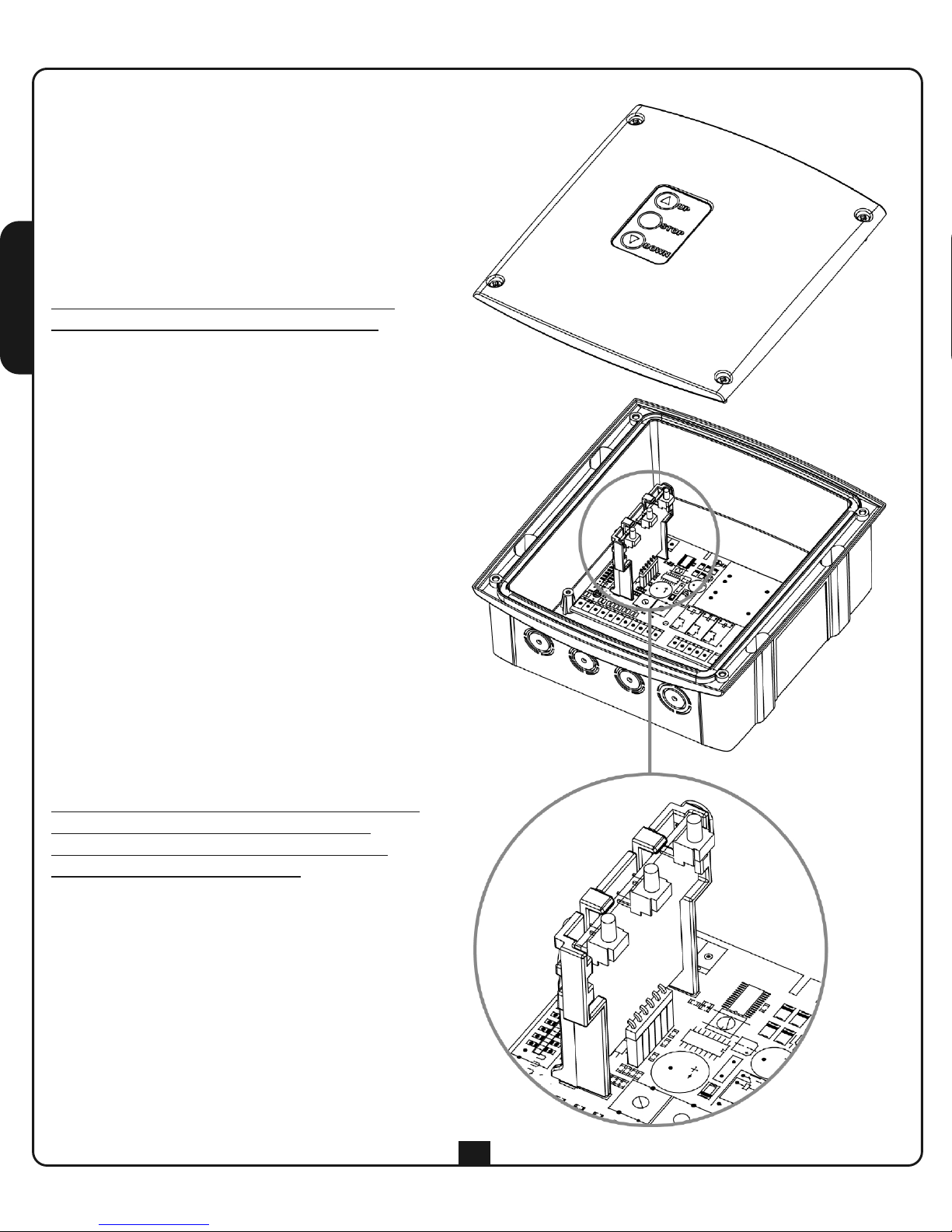
The EASY3 and EASY4 control units may be
installed in cases with external keypads
(accessory codes 171224 + 171226).
To use the keypad buttons, it is essential to
install adapter 171226 as shown in the figure.
Alternatively, the WES-EASY accessory may be
installed (code 35B025), which besides using
the keypad allows controlling the edges by
radio using the special sensors (see the
WES-EASY instructions).
The keypad buttons operate in parallel with the
terminal controls. These all remain active,
including the STOP command, and must be
jumpered to ground if not used.
Versions supplied with keypads also allow the
automation device to operate in MAN PRESENT
mode should the safety devices malfunction.
By pressing and holding the button on the
keypad, the automation device is activated
after 5 seconds, overriding the safety devices;
the motor stops immediately as soon as the
button is released.
Page 9
ENGLISH
23
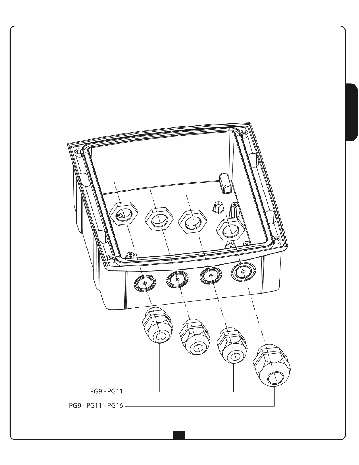
CABLE GLAND ASSEMBLY
The casing can accept 4 cable glands in the special easy-break housings.
The type of cable gland is indicated in the figure.
PLEASE NOTE:
• Remove the electronic circuit board before drill the casing.
• Drill the container using a suitably sized cutter, according to the dimensions of the cable gland.
• Fix the cable glands using the special nuts.
Page 10
ENGLISH
24
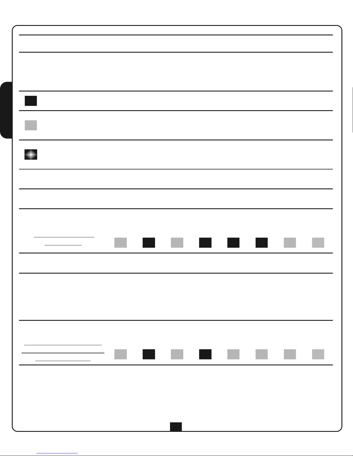
When the main control unit is in standby mode, the eight LEDs on the card display the status of the inputs
CONTROL UNIT
IN STANDBY
displaying the status
of the inputs
start
up
open
stop
auto
down
photo edge
dm
fire
canc
light
motor
test
error
To display the operational logics set, press the MENU button for at least 2 seconds: the LEDs come on (for 12
seconds) depending on the status of the various functions.
PLEASE NOTE: the following display refers to the default factory settings
CONTROL UNIT
IN PROGRAMMING MODE
displaying the status of the
functions (please refer to the
FUNCTIONS TABLE)
start
up
open
stop
auto
down
photo edge
dm
fire
canc
light
motor
test
error
DISPLAYING THE SET FUNCTIONS
Besides displaying the status of the inputs and the operational cycle, during programming, the eight LEDs on
the card display the status of the various functions. Each LED corresponds to a function, and its status
(on/off) indicates the mode with which it has been set (please refer to the FUNCTIONS TABLE)
LED ON (indicates the function is enabled)
LED OFF (during the “DISPLAYING THE SET FUNCTIONS” phase indicates that the
function is disabled)
LED FLASHING (during the “MODIFY FUNCTIONS” phase indicates that the function
is disabled)
Page 11
ENGLISH
25
ALTERING THE FUNCTIONS
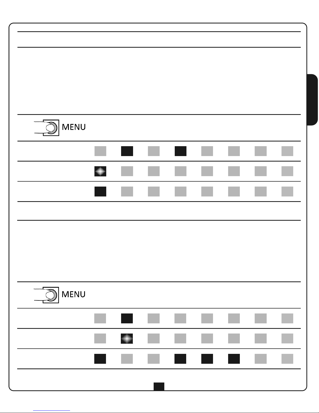
To alter the operational logics, proceed as follows:
1. Press and hold the MENU button for at least 2 seconds: the LEDs come on (for 12 seconds) depending
on the status of the various functions.
2. Press the MENU button briefly: the start/up LED flashes to indicate the function is disabled.
Then, based on the function table, function 1 is set to START/STOP LOGIC
3. To alter the status of this function, press and hold the MENU button until the start/up LED comes on
(fixed)
STEP
start
up
open
stop
auto
down
photo edge
dm
fire
canc
light
motor
test
error
1 2s < T < 5s
2 T < 1s
3 2s < T < 5s
4. When the status of the function has been altered, press the MENU button briefly to select the next
function to be altered: if the corresponding LED is on, this means that the function is enabled; if flashing
it is disabled.
5. To alter the status of the selected function, press and hold the MENU button until the LED changes
its status
6. To exit from the function programming menu, wait for 10 seconds after the last operation: the main
control unit displays the new function configuration for 12 seconds, then returns to standby mode
STEP
start
up
open
stop
auto
down
photo edge
dm
fire
canc
light
motor
test
error
4 T < 1s
5 2s < T < 5s
6 -
Page 12
ENGLISH
26
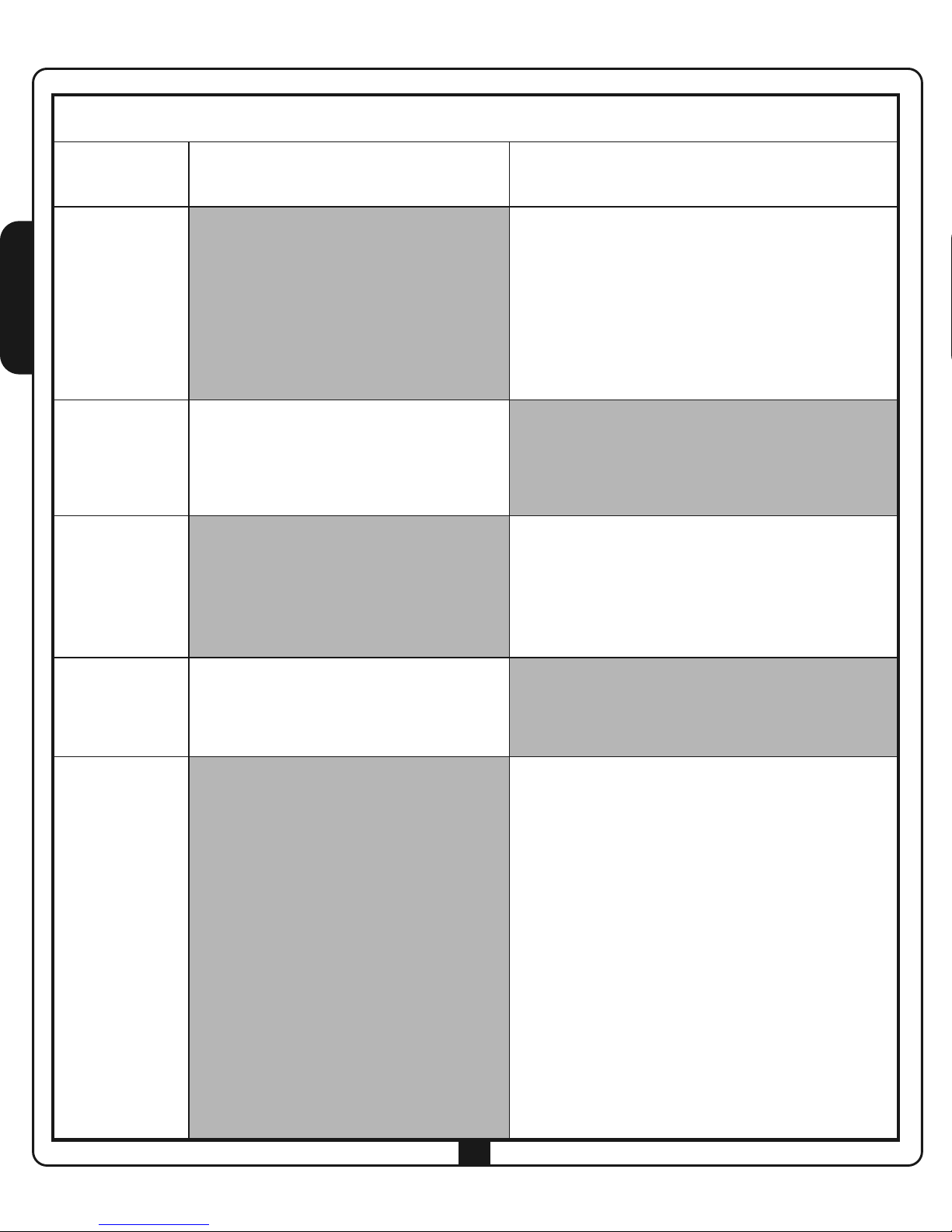
FUNCTION TABLE (the highlighted boxes indicate the factory default settings)
FUNCTION
(LED)
LED OFF LED ON
1. start/up
START/STOP LOGIC
The START/UP input controls the STEP
or AUTOMATIC operational cycle based
on the programmed operational logic.
The DOWN input is inactive
UP/DOWN LOGIC
The START/UP input always controls opening
and the DOWN input always controls closing,
independently of the operational logic
programmed.
UP + DOWN when pressed simultaneously is the
same as a STOP command
2. open/stop
START INACTIVE WHILE OPENING
During opening, the START command
is ignored
START ACTIVE WHILE OPENING
During opening, the START command
interrupts opening (no timer is set for automatic
re-closure)
3. auto/down
STEP LOGIC
The start command activates an
OPEN-STOP-CLOSE-STOP-OPEN
operational cycle
AUTOMATIC LOGIC
The start command activates an
OPEN-PAUSE-CLOSE-STOP operational cycle
Closure starts automatically after the pause
time set
4. photo
PHOTOCELL INACTIVE WHILE
OPENING
Photocell intervention during opening is
ignored
PHOTOCELL ACTIVE WHILE OPENING
Photocell intervention during opening causes
the motor to stop until it is released
5. edge
EDGE TEST INACTIVE
The edge operation test is not
performed
EDGE TEST ACTIVE
Each time the main control unit receives an
open or close command, the EGDE TEST verifies
the edge is operating correctly.
If the test fails, the edge LED flashes at 2 Hz for
5 seconds, together with the motor/test/error
LED.
During the TEST, the main control unit also
recognises whether the edge provides a
normally closed contract or an impedance
(conductive rubber edge).
PLEASE NOTE: if a conductive rubber edge
is used, it is essential to activate the EDGE
TEST, as otherwise the edge is not
recognised.
Page 13
ENGLISH
27
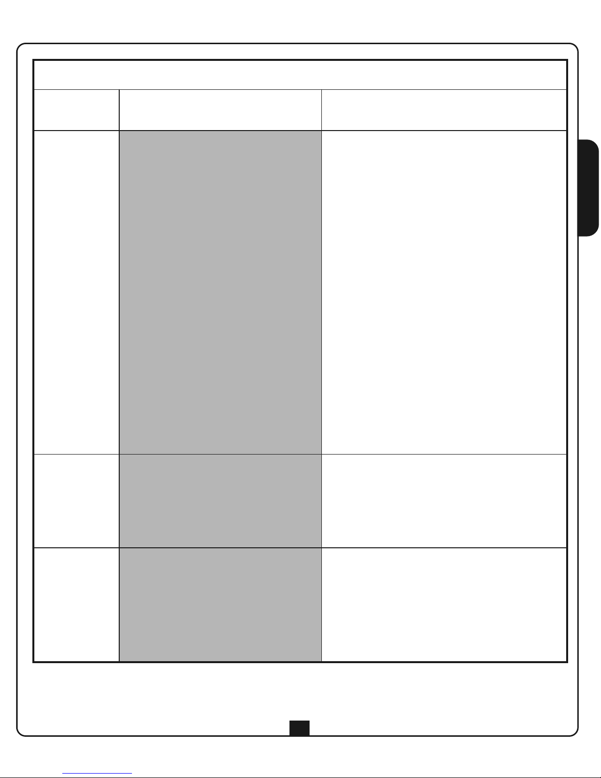
FUNCTION TABLE (the highlighted boxes indicate the factory default settings)
FUNCTION
(LED)
LED OFF LED ON
6. dm/fire
MAN PRESENT LOGIC INACTIVE
By simply using the start command, the
user can activate the automation device
in opening or closing.
The maximum duration of opening or
closing depends on the operating time
set
MAN PRESENT LOGIC ACTIVE
The user must press and hold the start button
for the entire duration of the desired opening or
closing procedure.
The maximum duration of opening or closing
depends on the operating time set.
MAN PRESENT logic may be implemented with
both Start/Stop and Up/Down logic.
The STOP command interrupts the operational
cycle, independently of the status of the control
inputs. Hence, if the UP or DOWN button is
pressed, the action of STOP is to stop motion,
and on its release the motor DOES NOT MOVE
UNTIL THE UP or DOWN INPUT IS RELEASED
AND PRESSED ONCE MORE
PLEASE NOTE: when the Man-Present
function is enabled, radio-controlled
operation is disabled
7. light/canc
FLASHING
Output (E1 - E2) is on intermittently (2
Hz) during opening and closing and
during pause mode, if automatic
reclosing is active
COURTESY LIGHT
The output (E1 - E2) is on and fixed during
opening, pause and closure. Having completed
the operating cycle, the light remains on for the
COURTESY LIGHT OFF DELAY time
8. motor/test
/error
PHOTOCELL TEST INACTIVE
The photocell operation test is not
performed
PHOTOCELL TEST ACTIVE
Each time the control unit receives an open or
close command, the PHOTOCELL TEST verifies
that the PHOTOCELL is operating correctly.
If the test fails, the photo LED flashes at 2 Hz
for 5 seconds, together with the
motor/test/error LED
Page 14
ENGLISH
28
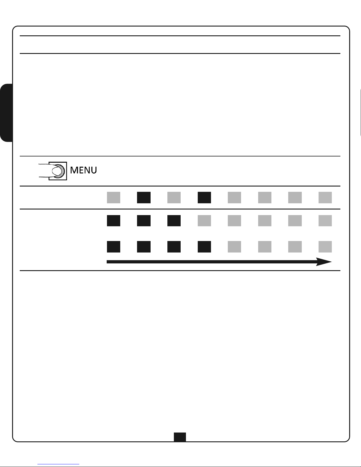
ADJUSTING THE OPERATING TIME
To alter the motor operating time, proceed as follows:
1. Press and hold the MENU button for at least 2 seconds: the LEDs display the status of the various
functions
2. Within 10 seconds, press the MENU button for at least 2 seconds: the LEDs come on showing the
operating time set (20 seconds by default)
3. Press the MENU button briefly to alter the operating time. Each time the button is pressed, the time is
increased up to a maximum of120 seconds, subsequent pressing restarts the time from a minimum
value of 10 seconds
4. To exit from the programming menu, wait for 12 seconds: the main control unit returns to standby
mode, storing the new settings
STEP
start
up
open
stop
auto
down
photo edge
dm
fire
canc
light
motor
test
error
1 2s < T < 5s
2 2s < T < 5s
10s 15s 20s 30s 45s 60s 90s 120s
3 T < 1s
Page 15
ENGLISH
29
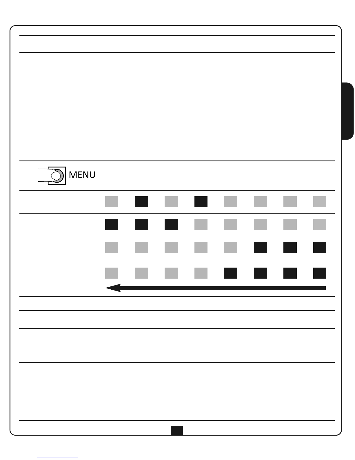
ADJUSTING THE PAUSE TIME
To alter the motor pause time, proceed as follows:
1. Press and hold the MENU button for at least 2 seconds: the LEDs display the status of the various functions
2. Within 10 seconds, press the MENU button for at least 2 seconds: the LEDs come on showing the
operating time set (20 seconds by default)
3. Within 10 seconds, press the MENU button for at least 2 seconds: the LEDs come on showing the pause
time set (30 seconds by default)
4. Press the MENU button briefly to alter the pause time. Each time the button is pressed, the time is
increased up to a maximum of 180 seconds, subsequent pressing starts the time again from a minimum
value of 15 seconds.
5. To exit from the programming menu, wait for 12 seconds: the main control unit returns to standby
mode, storing the new settings
STEP
start
up
open
stop
auto
down
photo edge
dm
fire
canc
light
motor
test
error
1 2s < T < 5s
2 2s < T < 5s
2s < T < 5s
180s 120s 90s 60s 45s 30s 20s 15s
3 T < 1s
ADJUSTING THE COURTESY LIGHT OFF DELAY
When the main control unit returns to standby mode after an operational cycle, the courtesy light remains
on for a programmable length of time up to 5 minutes. The off delay may only be set if the output is set as
the courtesy light (function 7 – please refer to the FUNCTION TABLE).
To alter the courtesy light off delay, proceed as follows:
1. Press and hold the MENU button, ignoring the virtual dip switch display on the LEDs
2. After 5 s the LEDs are switched off and the courtesy light switched on
3. Continue holding the MENU button for the period of time it is desired to set
4. Release the MENU button. The courtesy light is switched off and the length of time for which it was on is
stored as the off delay
Page 16
ENGLISH
30
OPERATION WITH REMOTE CONTROL
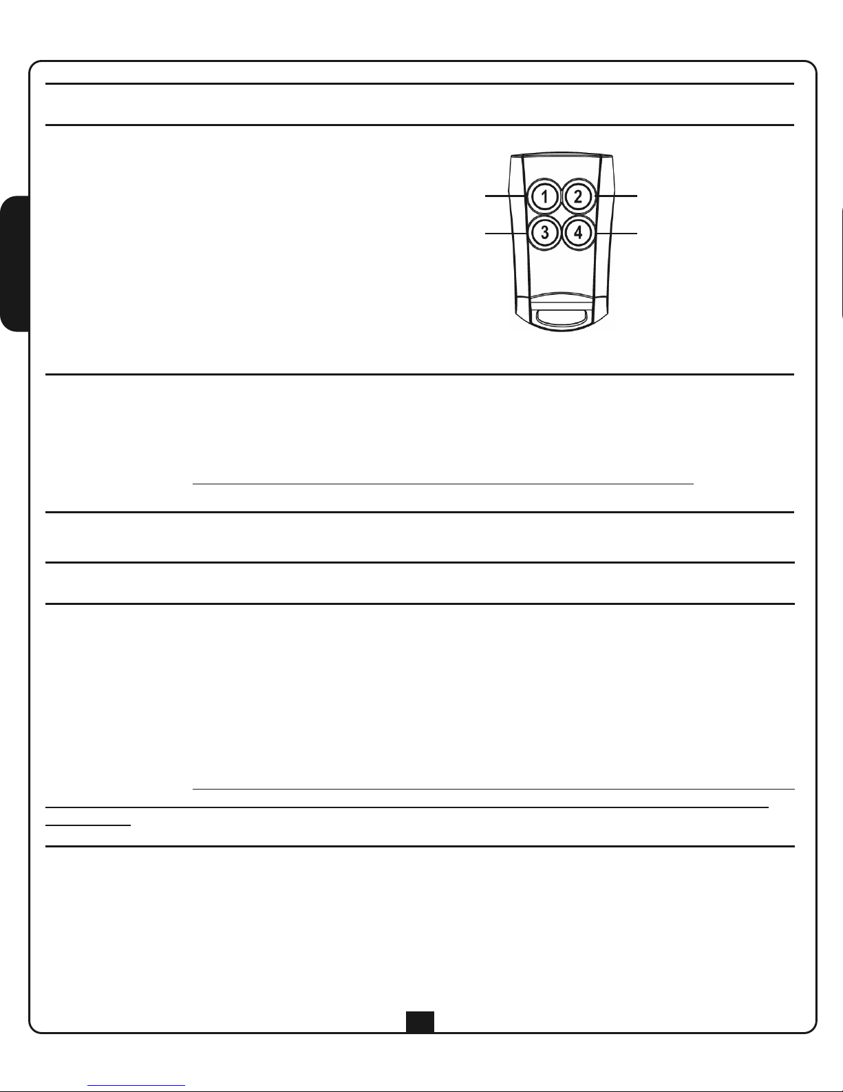
Operation of the remote control units depends on
the configuration of function 1.
START/STOP logic: only the memorised button
activates an OPEN or CLOSE command.
UP/DOWN logic: each button on the remote
control is associated with a function.
Simply memorise any button on the remote control
to activate operation of the other 3 buttons.
* The courtesy light can be controlled by button 4 on the remote control.
The operational logic is bistable: if the courtesy light is off, it comes on, and vice versa. In any case, the light
switches off after 10 minutes.
PLEASE NOTE: It is not possible to switch off the courtesy light while the door is moving.
UP
DOWN
STOP
COURTESY LIGHT*
MEMORISING REMOTE CONTROL UNITS
1. Press the MENU button briefly
2. The control unit activates the radio acquisition phase: the LEDs come on rapidly, moving from left to right
3. Within 5 seconds, transmit using the button on the remote control it is desired to memorise
4. All the LEDs come on for 2 s to indicate the remote control unit has been memorised
5. The control unit switches to radio acquisition mode for 5 s: the LEDs come on rapidly, moving
from left to right
6. Transmit using another remote control unit to be memorised, or wait for the LEDs to turn off
PLEASE NOTE: when the memory is full, and hence it is not possible to memorise other remote control
units, any attempt to activate radio acquisition will result in the control unit responding by flashing all the
LEDs for 2 s.
Page 17
ENGLISH
31
DELETING ALL THE REMOTE CONTROL UNITS
The delete all the codes in the memory, proceed as follows:
1. Disconnect the power from the main control unit
2. While pressing and holding the MENU button, reconnect the power: the light/del LED flashes
3. Release the MENU button within 5 seconds: all the LEDs come on for 2 s and the control unit returns to
standby mode
WARNING: If the key is not released within 5 secs., the motor/test/error led will also start to flash
and the control unit blocks. To unblock it, disconnect then reconnect power supply
DISTANCE MEMORISING OF REMOTE CONTROL UNITS
This procedure allows remote control units to be memorised without the need for direct access to the main
control unit.
To activate this procedure, at least one remote control unit must already be memorised with the main
control unit.
Proceed as follows:
1. Simultaneously press and hold buttons 1 and 2 (or 1 and 3) for 5 seconds
2. The control unit activates the radio acquisition phase: the LEDs come on rapidly from left to right and the
courtesy light also comes on
3. Within 5 seconds, transmit using the button on the remote control it is desired to memorise
4. The courtesy light is switched off for one second to indicate the remote control has been memorised
5. The control unit switches to radio acquisition mode for 5 s: the LEDs come on rapidly from left to right
and the courtesy light also comes on
6. Transmit using another remote control unit to be memorised, or wait for the LEDs and the courtesy light
to be turned off
Page 18
ENGLISH
32
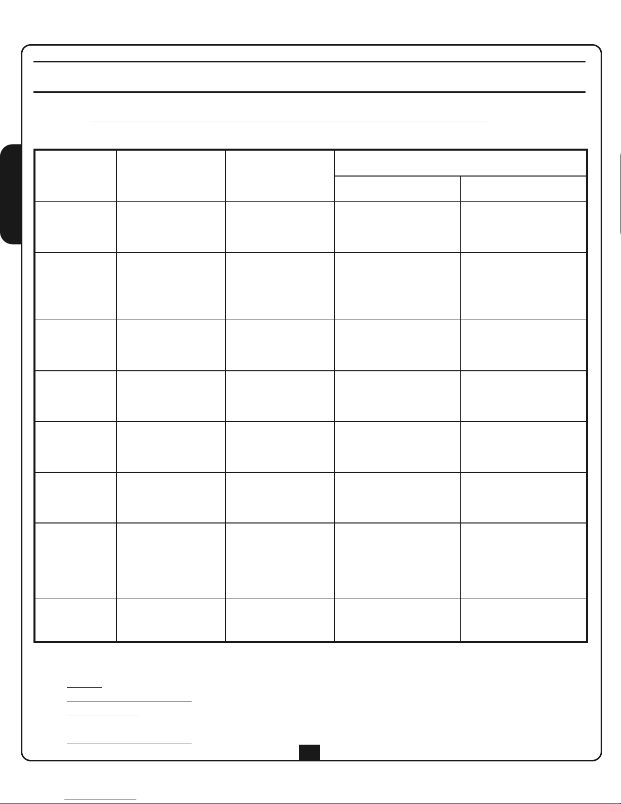
LED OFF ON
FLASHING led (combined with led 8)
Led 8 is OFF or ON Led 8 is BLINKING
1. start/up
On the start/up
terminal, the
contact is open
On the start /up
terminal, the
contact is closed
Start command
received from remote
control
Writing in flash at the
end of the
programming is failed
2. open/stop
On the open/stop
terminal, the
contact is open
On the open/stop
terminal, the
contact is closed
Stop command
received from remote
control or start aborted
due to stop being on
-
3. auto/down
On the down
terminal, the
contact is open
On the down
terminal, the
contact is closed
Down command
received from remote
control
-
4. photo
On the photo
terminal, the
contact is open
On the photo
terminal, the
contact is closed
Start aborted due to
inter-rupted photocell
detection
Photocell test is failed
5. edge
On the edge
terminal, the
contact is open
On the edge
terminal, the
contact is closed
Start aborted due to
pressed edge detection
Edge test is failed
6. dm/fire
On the fire
terminal, the
contact is open
On the fire
terminal, the
contact is closed
Start aborted due to
fire alarm being on
-
7. light/canc - -
Light command received
from remote control or
opening cycle* phase
indication or remote
control codes erasure
Remote control codes
erasure is failed
8. motor/test
/error
The motor is not
activated
The motor is
activated
Error indication
* Operating cycle: the 7 leds (light / delete) switch on following the logic below:
• Led off
: control unit off
• Flashing light led at 2 Hz: opening phase
• Permanent led: control unit off with shutter open (if the timer is on for automatic closing, the led
turns off briefly, every half a second)
• Flashing light led at 4 Hz
: closing phase
VISUALISATION AND SIGNALLING USING LED
A row of 8 red leds is fitted to the card, via which all the useful signals for installation and usage are
controlled. During the normal running of the control unit (NOT at the programming stage), the meaning of
each led can be found in the following table:
Page 19

Page 20
V2 S.p.A.
Corso Principi di Piemonte, 65/67
12035 RACCONIGI (CN) ITALY
tel. +39.0172.812411
fax +39.0172.84050
info@gatestore.co.uk www.remotecontrolgates.co.uk
 Loading...