

Page 1

ATTUATORE ELETTROMECCANICO IRREVERSIBILE
PER CANCELLI A BATTENTE
IRREVERSIBLE ELECTROMECHANICAL ACTUATOR
FOR SWING GATES
OPERATEUR ELECTROMECANIQUE IRREVERSIBLE
POUR PORTAILS BATTANTS
OPERADOR ELECTROMECÁNICO IRREVERSIBLE
PARA CANCELAS BATIENTES
ACTUADOR ELECTROMECÂNICO IRREVERSÍVEL
PARA PORTÕES DE BATENTE
NICHT UMKEHRBARER ELEKTROMECHANISCHER
ANTRIEB FÜR FLÜGELTORE
ELEKTROMECHANISCHE, ONOMKEERBARE
LINEAIRE MOTOR VOOR HEKKEN MET VLEUGELS
I
GB
F
E
P
D
NL
CALYPSO
IL n. 186
EDIZ. 04/03/2010
V2 S.p.A.
Corso Principi di Piemonte, 65/67
12035 RACCONIGI (CN) ITALY
tel. +39 01 72 81 24 11 - fax +39 01 72 84 050
info@v2home.com - www.v2home.com
Page 2

7
IMPORTANT REMARKS
For any installation problem please contact our Customer Service
at the number +39-0172.812411 operating Monday to Friday
from 8:30 to 12:30 and from 14:00 to 18:00.
V2 has the right to modify the product without previous
notice; it also declines any responsibility to damage or
injury to people or things caused by improper use or
wrong installation.
Please read this instruction manual very carefully
before installing and programming your control unit.
• This instruction manual is only for qualified technicians, who
specialize in installations and automations.
• The contents of this instruction manual do not concern the
end user.
• Every programming and/or every maintenance service should
be done only by qualified technicians.
AUTOMATION MUST BE IMPLEMENTED IN COMPLIANCE
WITH THE EUROPEAN REGULATIONS IN FORCE:
EN 60204-1 (Machinery safety electrical equipment of
machines, part 1: general rules)
EN 12445 (Safe use of automated locking devices, test
methods)
EN 12453 (Safe use of automated locking devices,
requirements)
• The installer must provide for a device (es. magnetotermical
switch) ensuring the omnipolar sectioning of the equipment
from the power supply.
The standards require a separation of the contacts of at
least 3 mm in each pole (EN 60335-1).
• The plastic case has an IP55 insulation; to connect flexible
or rigid pipes, use pipefittings having the same insulation
level.
• Installation requires mechanical and electrical skills,
therefore it shall be carried out by qualified personnel only,
who can issue the Compliance Certificate concerning the
whole installation (Machine Directive 2006/42/CEE, Annex IIA).
• The automated vehicular gates shall comply with the
following rules: EN 13241-1, EN 12453, EN 12445 as well as
any local rule in force.
• Also the automation upstream electric system shall comply
with the laws and rules in force and be carried out
workmanlike.
• The door thrust force adjustment shall be measured by
means of a proper tool and adjusted according to the max.
limits, which EN 12453 allows.
• We recommend to make use of an emergency button, to be
installed by the automation (connected to the control unit
STOP input) so that the gate may be immediately stopped
in case of danger.
• The appliance is not to be used by children or persons with
reduced physical, sensory or mental capabilities, or lack of
experience and knowledge, unless they have been given
supervision or instruction.
• Children being supervised do not play with the appliance.
• For correct installation of the system, we recommend
following the instructions issued by UNAC very carefully,
which can be consulted at the following web site:
www.v2home.com
EC DECLARATION OF INCORPORATION FOR
PARTLY COMPLETED MACHINERY
(Directive 2006/42/EC, Annex II-B)
The manufacturer V2 S.p.A., headquarters in
Corso Principi di Piemonte 65, 12035, Racconigi (CN), Italy
Under its sole responsibility hereby declares that:
the partly completed machinery model(s):
CALYPSO400-230V, CALYPSO500-230V
CALYPSO400-120V, CALYPSO500-120V
Identification number and year of manufacturing: typed on
nameplate
Description: electromechanical actuator for gates
- is intended to be installed on gates, to create a machine
according to the provisions of the Directive 2006/42/EC.
The machinery must not be put into service until the final
machinery into which it has to be incorporated has been
declared in conformity with the provisions of the Directive
2006/42/EC (annex II-A).
- is compliant with the applicable essential safety requirements
of the following Directives:
Machinery Directive 2006/42/EC (annex I, chapter 1)
Low Voltage Directive 2006/95/EC.
Electromagnetic Compatibility Directive 2004/108/EC.
The relevant technical documentation is available at the national
authorities’ request after justifiable request to:
V2 S.p.A., Corso Principi di Piemonte 65,
12035, Racconigi (CN), Italy
The person empowered to draw up the declaration and to
provide the technical documentation:
Cosimo De Falco
Legal representative of V2 S.p.A.
Racconigi, 11th January 2010
ENGLISH
Page 3
ENGLISH
8
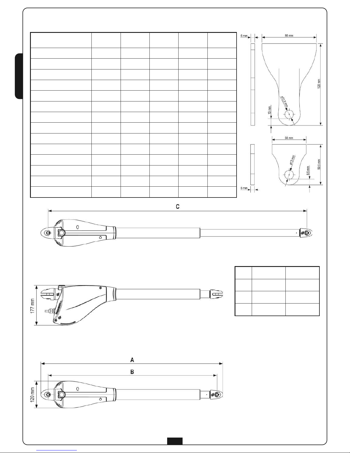
TECHNICAL DATA
Calypso400 Calypso500
Calypso
400-120V
Calypso
500-120V
Max. leaf lenght m 2,5 3 2,5 3
Max. leaf weight Kg 400 500 400 500
Power supply VAC - Hz 230 - 50 230 - 50 120 - 60 120 - 60
Idling current A 1 1 2 2
F
ull load current
A 1
,4
1
,4
2
,8
2
,8
Maximum Power W 300 300 300 300
Capacitor µF 8 8 25 25
Max travel mm 400 500 400 500
Operating speed m/s 0,016 0,016 0,018 0,018
Maximum thrust N 2600 2600 2600 2600
Working temperature °C -30 ÷ +60 -30 ÷ +60 -30 ÷ +60 -30 ÷ +60
Protection IP 44 44 44 44
Working cycle % 30 30 30 30
Motor weight Kg 6,5 6,8 6,5 6,8
Calypso400 Calypso500
A 819 944
B 762 887
C 1162 1387
Page 4

9
INSTALLATION LAYOUT
CALYPSO actuator
cable 4 x 1 mm
2
Blinker
cable 2 x 1,5 mm
2
Aerial
cable RG-58
Key or digital selector
cable 2 x 1 mm
2
Internal photocells
cable 4 x 1 mm2(RX)
cable 2 x 1 mm2(TX)
External photocells
cable 4 x 1 mm2(RX)
cable 2 x 1 mm2(TX)
Safety edge (EN 12978)
-
Control unit
cable 3 x 1,5 mm
2
PREPARATORY STEPS
The new series of actuadors CALYPSO, has been devised to serve gates up to 500 Kg with leaf up to 3 meters wide (look at the table
technical data). Before proceeding with the installation, please make sure that your gate opens and closes freely, and that:
• Hinges and pins are in optimum condition and properly greased.
• No obstacles are within the moving area.
• There is no friction with the ground or between the leaves.
• Your gate shall be equipped with central and side stops, which are fundamental for the good system operation.
ENGLISH
Page 5

10
INSTALLATION MEASURES
To carry out a proper installation of the operator parts as well as
to ensure the best automation performance, the measurement
levels shown in the following table shall be complied with.
Change the gate structure to adapt it to one of the cases in the
table, if necessary.
WARNING: In the case of leaf longer than 2 metres,
an electric lock must be fitted to ensure an efficent closig.
CALYPSO 400
γ
A [mm] B [mm] C [mm] F [mm]
90°
20 130 130 1010
40 150 140 1000
60 170 150 990
80 190 150 980
100 200 150 980
120 210 140 980
140 250 120 1010
100°
20 130 170 970
40 150 180 960
60 170 180 960
80 190 170 970
100 210 140 990
110°
20 130 190 950
40 150 180 960
50 160 170 970
CALYPSO 500
γ
A [mm] B [mm] C [mm] F [mm]
90°
20 130 170 1200
40 150 180 1190
60 170 180 1190
80 190 190 1180
100 210 190 1170
120 230 190 1170
140 250 180 1170
160 270 190 1170
180 290 170 1180
100°
20 130 160 1210
40 150 170 1200
60 170 170 1200
80 200 180 1190
100 210 170 1190
120 230 190 1170
140 250 180 1180
160 270 160 1200
170 280 160 1200
110°
20 130 170 1200
40 150 180 1190
60 170 180 1190
80 190 190 1180
100 210 200 1170
110 220 200 1170
ENGLISH
Page 6

11
ACTUATOR FIXING
Choose measures referring to the table you can find in the
previous page, mark them on the pillars and continue as follows:
• Fix the clamps to the pillar and to the gate soldering
directly; if the material does not allow it, it is necessary to
solder the clamps to plates to be fixed to the gate and the
pillars by screws.
• Close the swing.
• Unlock the actuators.
• Position CALYPSO on the brackets and fix the pins no. 1 and
no. 2 with seeger (see the picture).
• Open and close the swings repeatedly manually to verify the
absence of frictions between gate and ground.
WARNING: in order to avoid damage to the actuator,
please adhere to the following conditions:
• The brackets must be installed at the same height.
• The maximum stroke of arm A should not exceed 456 mm
for CALYPSO400 and 556 mm for CALYPSO500 (in case of
gate completely closed).
• The minimum stroke of arm B must be more than 56 mm (in
case of gate completely open).
ENGLISH
Page 7

ENGLISH
12
TO CONNECT CALYPSO WITH CONTROL UNIT
WARNING: always remember to connect the earth
according to current standards (EN 60335-1, EN 60204-1).
Avoid tension in the cable during open and close operations
.
EMERGENCY RELEASE
In case of a blackout, the gate can be operated
directly from the motor. Insert the key supplied
in the lock, perform 1/2 of a turn.
To restore the automation, simply rotate the key
in closed position and insert the provided plastic
cover onto the lock.
YELLOW - GREEN GND
BLUE (230V mod.)
WHITE (120V mod.)
COMMON
BLACK CLOSING
BROWN OPENING
 Loading...