

UYAR VisionLine RWC, VisionLine EC, VisionLine EAC, VisionLine RWC 88 HDMI Operating Instructions Manual [en, de]
Page 1

Operating instructions
VisionLine RWC
VisionLine EAC
VisionLine EC
Page 2

Operating instructions VisionLine
Inhaltsverzeichnis
Notes on symbols and markings �������������������������������������������������������������������� 3
Preface ���������������������������������������������������������������������������������������������������������� 4
Illustration of the EC declaration of conformity VisionLine RWC ���������������������� 5
1 Introduction ���������������������������������������������������������������������������������������������� 7
1.1 Liability .................................................................................................... 7
1.2 Warranty ................................................................................................. 7
1.3 Return andhandling ................................................................................. 8
2 Description of the camera system �������������������������������������������������������������� 8
2.1 Intenden use ............................................................................................ 8
2.2 Structure of the camera systems ............................................................... 10
3 Installation ��������������������������������������������������������������������������������������������� 12
3.1 Before Installation .................................................................................. 12
3.2 Mechanical installation ........................................................................... 13
3.3 Electrical installation ............................................................................... 20
3.4 Pneumatic installation ............................................................................. 23
4 Operation ����������������������������������������������������������������������������������������������� 24
4.1 Commisioning ....................................................................................... 24
4.2 Control ................................................................................................. 25
4.3 Maintenance / Servicing ......................................................................... 26
4.4 Error diagnostics .................................................................................... 29
4.5 Decomissioning / Disposal ...................................................................... 30
5 Appendix ������������������������������������������������������������������������������������������������ 30
Page 3

Operating instructions VisionLine
Notes on symbols and markings
This operating manual uses symbols and images to help you understand how to use the product safely
and to warn you of potential hazards due to incorrect connection, mounting, selection and operation. It
is important that you know the meaning of the notes to this manual exactly in order to use this camera
system correctly.
HAZARD
This hazard note indicates an imminently hazardous situation which, if not avoided, will
result in death or serious injury.
WARNING
CAUTION
NOTICE
This hazard note indicates a potentially hazardous situation which, if not avoided, may
result in death or a serious injury.
This hazard note indicates a potentially hazardous situation which, if not observed, may
result in minor or moderate injuries.
This notice indicates possible damage to property or a process of special interest / importance that may arise if the safety measures are not followed.
3
3
Page 4
Operating instructions VisionLine
Preface
NOTICE
Read these operating instructions carefully to gain a thorough understanding of the camera system and its operation and maintenance. Only use the device in accordance with
this manual to avoid personal injury or property damage. Do not operate the device on
the basis of assumptions. Have the operating instructions available at the site of operation
of the camera system and consult it if you doubt the execution of any procedure. The manufacturer assumes no liability for problems caused by non-observance of these operating
instructions.
Costumer service
A.U. Uyar Technology Center e.K.
Carl-Bosch-Straße 6
33790 Halle (Westf.)
Germany
Tel.: +49 (0) 5201 / 97 180 - 0
Fax: +49 (0) 5201 / 97 180 - 29
E-Mail: [email protected]
Homepage: www.uyar-kameratechnik.de
Operating instructions
©2018 by A.U. Uyar Technology Center e.K.
Copyright of the operating instructions
The copyright to this manual remains with the A.U. Uyar Technology Center e.K.. These operating
instructions are intended for the operating personnel. It contains rules and drawings of a technical
nature which are not allowed, neither as a whole nor in part, to be reproduced, distributed or
exploited for the purposes of competition without authorization or communicated to others.
4
4
Page 5

Operating instructions VisionLine
Elektromagnetische Verträglichk eit (EMV) – Teil 6-2: Fachgrundnormen –
Störfestigkeit für Industriebereich
Elektromagnetische Verträglichkeit (EMV) – Teil 6-3: Fachgrundnormen – Störaussendung für Wohnbereich, Geschäfts- und Gewerbebereiche sowie Kleinbetriebe
Elektromagnetische Verträglichk eit – Teil 3-2: Grenzwerte – Grenzwerte für Oberschwingungsströme (Geräte-Eingangsstrom <= 16 A je Leiter)
Elektromagnetische Verträglichk eit – Teil 3-3: Grenzwerte – Begrenzung von
<= 16 A je Leiter, die keiner S onderanschlussbedingung unter liegen
Illustration of the EC declaration of conformity VisionLine RWC
Werkzeugmaschinen Kamera Typ: RWC 88 HDMI
2.6.2 EU-Konformitätserklärung
Technolo gy C en ter e. K .
Carl-Bosch-Straße 6
D-33790 Halle (Westfalen)
EU-Konformitätserklärung
im Sinne der
- EU-Richtlinie Elektrische Betriebsmittel 2014/35/EU
- EU-Richtlinie EMV 2014/30/EU
Bezeichnung: Werkzeugmaschinen Kamera
Typ: RWC 88 HDMI
Baujahr: 2017
Richtlinie / Norm Titel
DIN EN 61010-1 :2010
DIN EN 61000-6-2
DIN EN 61000-6-3
DIN EN 61000-3-2
DIN EN 61000-3-3
Sicherheitsbestimmungen für elektrisc he Mess-, Steuer-, Regel- und Laborgeräte
– Teil 1: Allgemeine Anforderungen
Spannungsänderungen, S pannungsschwankungen un d Flicker in öffentlichen
Niederspannungs-Versorgungsnetzen für Gerät e mit einem Bemessungsstrom
(ab 20.04.2016)
(ab 20.04.2016)
Der oben beschriebene Gegenstand der Erklärung erfüllt die einschlägigen Harmonisierungsrechtsvorschriften der Union.
Die oben aufgeführten harmonisierten Normen wurden zugrund e gelegt .
Halle (Westfalen), den 13.10.2017 ……................................................................
Unterschrift Geschäftsverantwortlicher
(Herr Ufuk Uya r, Geschäftsführer)
5
5
Page 6

Operating instructions VisionLine
6
6
Page 7

Operating instructions VisionLine
1 Introduction
The models of the VisionLine series are camera systems for visual process monitoring of wet and dry
areas. The camera used provides a high-resolution image that allows the user to monitor processes in
real time.
1�1 Liability
The removal of defects is only authorized by expert personnel of the manufacturer. The liability of the
manufacturer is limited to damage caused by normal use.
Violations
■ against the safety instructions,
■ against the notes of special hazards,
■ against the prohibition of unauthorized modifications and changes and
■ against the use of components and spare-parts that are not approved by the manufacturer
exclude the liability of the manufacturer for consequences. In these cases the liability is transferred to the
operator. A.U. UYAR Technology Center e.K. will charge the operator for any resulting repairs.
The manufacturer is not liable for any accidental loss resulting through thedue to use or non-use of this
product, such as loss of business incomesprofits.
1�2 Warranty
The operator of the camera system is not allowed to not make any changes or modifications without
our permission.
The used spare parts must be approved by us. This is guaranteed only with original spare parts from the
valid spare parts list.
Please contact us directly for possible warranty claims. The warranty for the camera system and accessories is limited to a period of 12 months from the date of the delivery note. The warranty can only be
claimed in conjunction with the proof of purchase.
Defects covered by the warranty will be remedied within the scope of these warranty conditions. If the
warranty claim is valid, we will repair or replace it. The decision on where the service is provided or
made available is up to us. The above warranty is exclusive and supersedes all other written, oral or
indirect warranties. For the product, it represents the only claim of the buyer and the only liability on our
part. Through performed warranty repairs, the original warranty period of the device is not extended.
During a warranty repair, we do not provide a replacement device. The sender is liable for transport
damages and losses that occur during the return to us.
We reserve the right to make technical changes for the purpose of product improvements or the technical progress.
7
7
Page 8
Operating instructions VisionLine
1�3 Return andhandling
Any warranty claim must be asserted during the warranty period and received by us in a timely manner.
If a product needs to be sent in for repair and/or adjustment, our consent is required beforehand (Phone: +49 (0) 5201/97 180 - 0).
Any material sent in for inspection and/or warranty repair should be insured for the means of transport
specified by us.
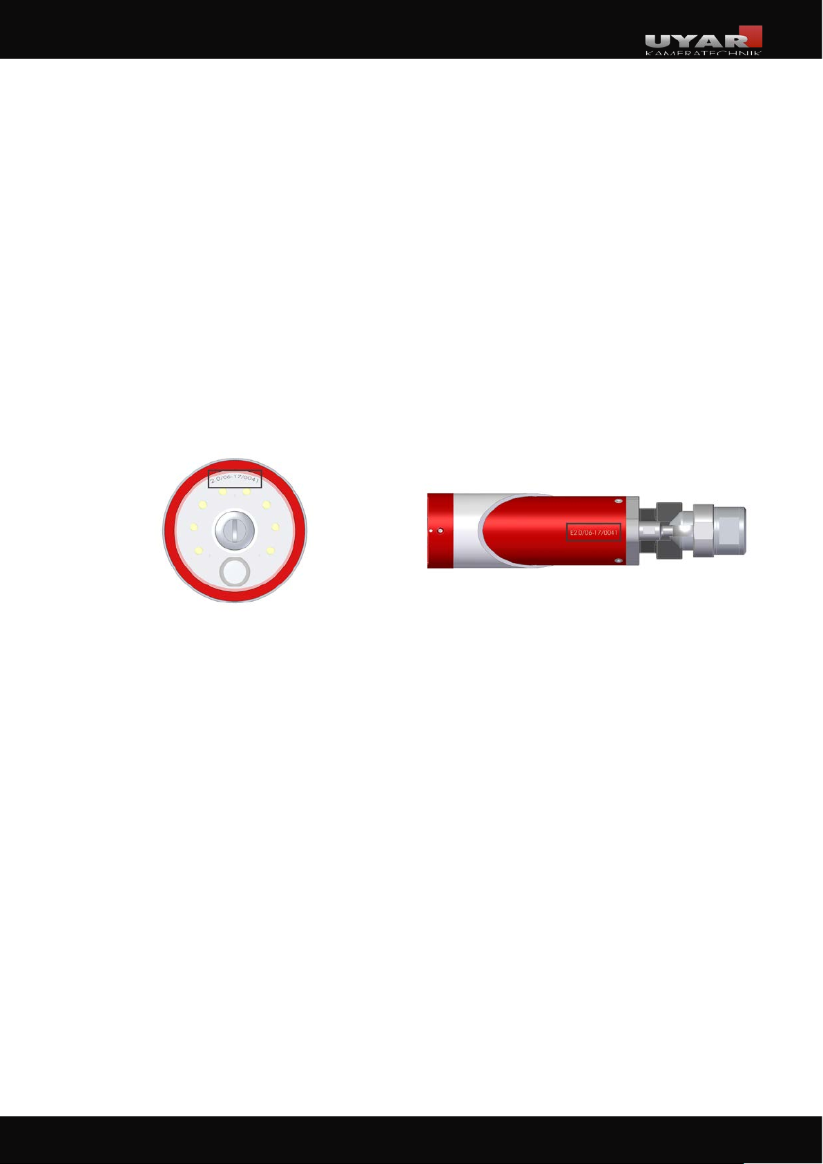
If a warranty claim exists, please indicate the serial number of the camera system. The general
responsibility for determining the cause and nature of an error and the final decision on it, is in any
case, exclusively with us.
Serial number VisionLine RWC Serial number VisionLine EAC / EC
2 Description of the camera system
2�1 Intenden use
Camera system VisionLine RWC and VisionLine EAC
In machine tools, coolants are used to reduce heat during the production process. The coolant is
slung away by the rotation of the tool or the part and adheres to walls and windows of the machine
interior, whereby the view of the operator is affected.
The UYAR camera systems of the RWC and EAC series are mounted inside the working area of a
machine tool. The rotating special pane of glass in the VisionLine RWC throws both the impinging
coolant and the chips away to the outside and thus out of sight. With the VisionLine EAC, this function
is performed by an air curtain generated by compressed air in front of the pane. The view of the
production process is clear.
8
8
Page 9
Operating instructions VisionLine
VisionLine EC
Thanks to the well-sealed housing with IP67 standard, the VisionLine EC models can be used wherever
conventional cameras fail after a short time. The housing of the VisionLine EC is not only dust- and
waterproof: All seals are also resistant to oils and cooling lubricants.
NOTICE
The coolant jet must not be directed at the camera system. The device must not be operated completely or partially under water, coolant or other liquids.
9
9
Page 10
Operating instructions VisionLine
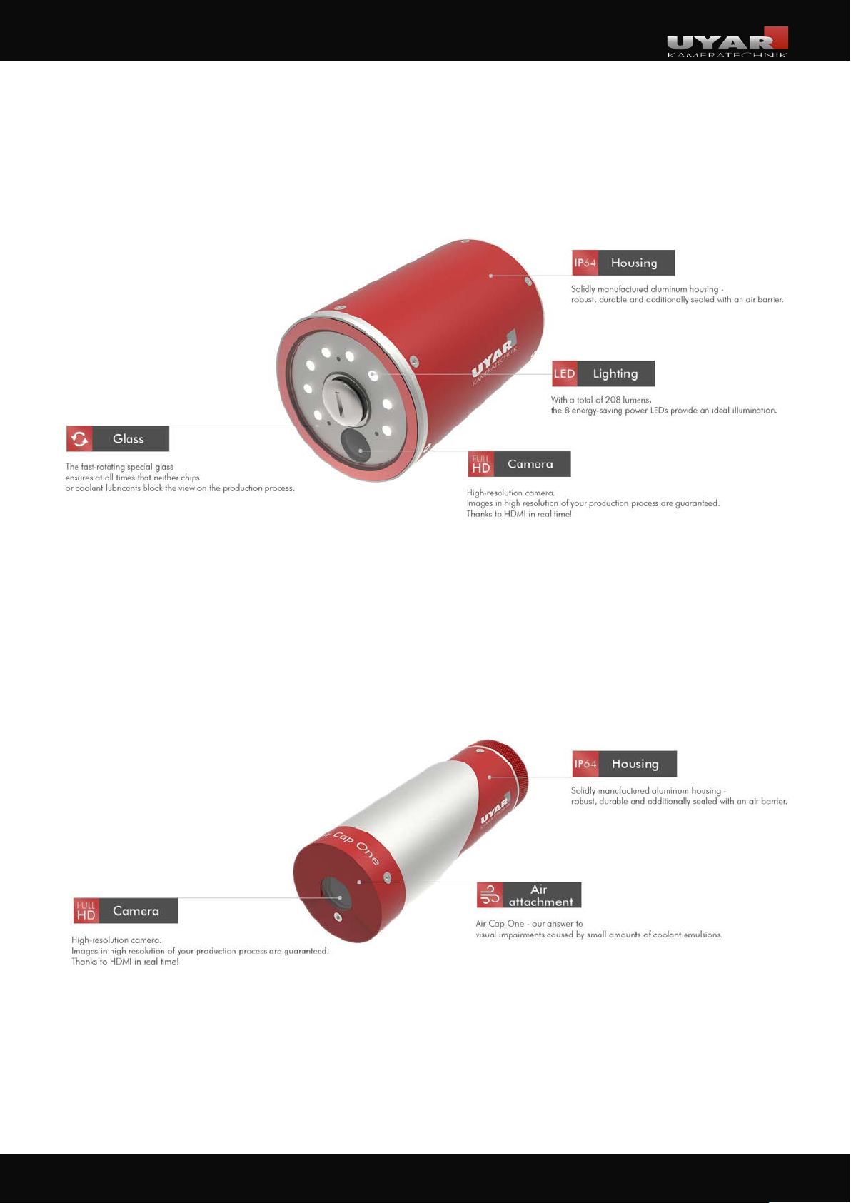
2�2 Structure of the camera systems
2�2�1 VisionLine RWC
2�2�2 VisionLine EAC
10
10
Page 11
Operating instructions VisionLine
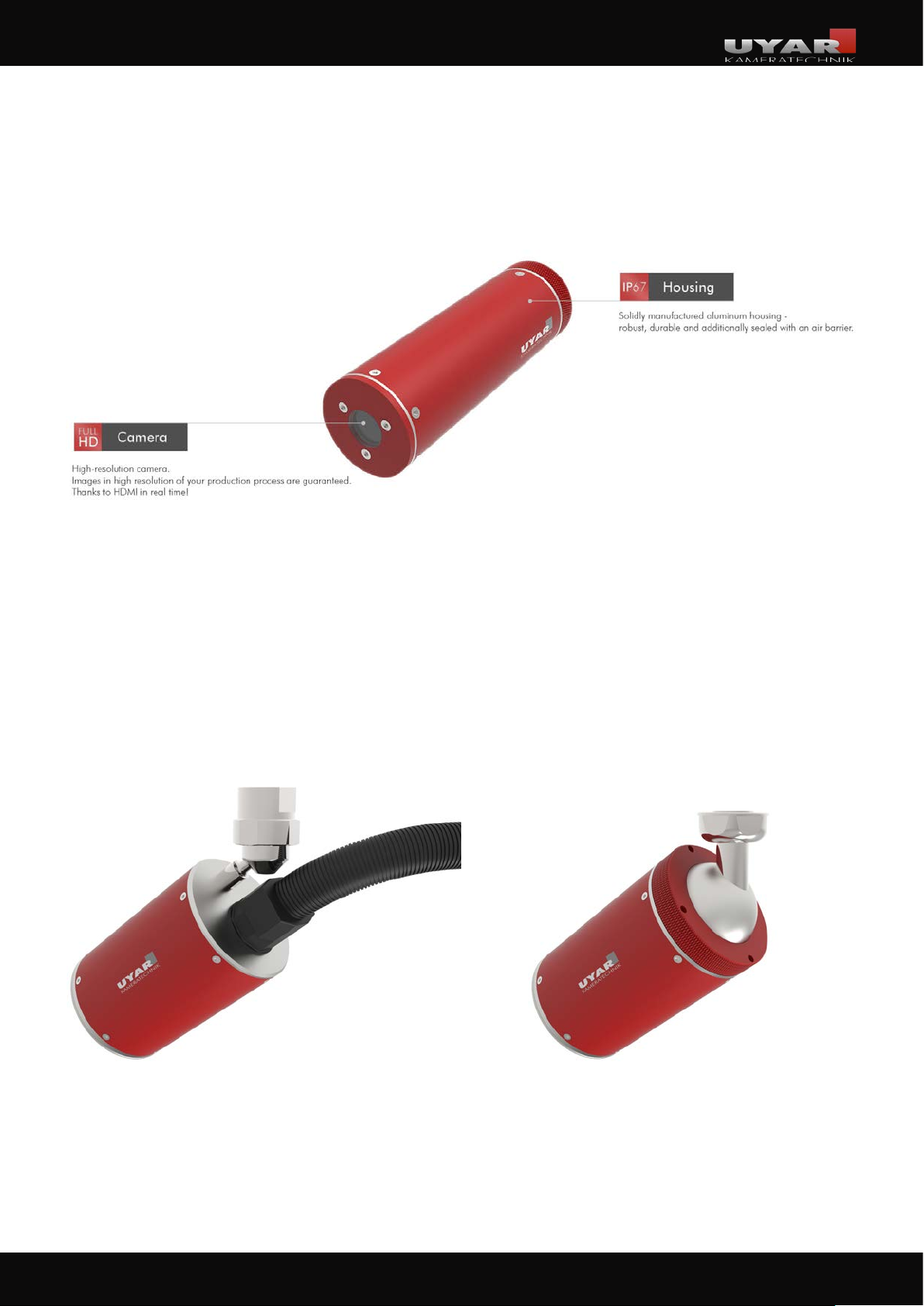
2�2�3 VisionLine EC
2�2�4 Hinge options
Hinge option 1
with external ball joint
Hinge option 2
with integrated ball joint
and cable bushing
11
11
Page 12
Operating instructions VisionLine
3 Installation
The installation of our camera systems is generally uncomplicated, but must be done exactly according
to the installation instructions listed in the following chapters.
The installation of the camera and the electrical installation is only permitted by qualified personnel.
These installation instructions include the standard installation for industrial processing machines. However, depending on the type of construction or the type of system another mounting style can be more
appropriate. If you have any questions, please contact us directly:
A.U. Uyar Technology Center e.K.
Carl-Bosch-Straße 6
33790 Halle (Westf.)
Germany
Phone: +49 (0) 5201 - 97 180 - 0
3�1 Before Installation
WARNING
The system to be equipped must be switched off by qualified personnel and secured
against being switched on again. Infringement may result in injury.
CAUTION
When working in the workspace, there is a risk of injury from edges. Wear suitable protective equipment!
First determine a suitable position for the camera system taking into account the following points:
■ The camera must be located outside possible collision areas,
■ The process to be observed must be optimally visible,
■ The coolant jet must not be directed at the camera system,
■ On the outside of the machine (opposite side of the cable bushing)) there must be
enough space for mounting the control box (if necessary, transfer the dimensions to the
outer wall of the machine and check the position of the control box separately).
A suitable and user-friendly mounting position should also be found for the monitor.
For smaller screens up to 22“ screen diagonal, the mounting above the HMI panel of the machine tool
is recommended. Depending on the application a different position may be more appropriate.
12
12
Page 13
Operating instructions VisionLine
3�2 Mechanical installation
The following installation instructions are valid for the VisionLine RWC, EAC and EC models. A
differentiation is made in the mechanical installation between the various hinge and installation
options. Please refer to one of the following chapters for the respective installation instructions for your
camera:
■ 3.2.1 Mounting the camera with external ball joint
■ 3.2.2 Direct wall mounting with integrated ball joint without cable-hose-package
■ 3.2.3 Wall mounting with integrated ball joint and cable-hose-package
For installation instructions on how to use the optional wall bushing, please refer to the chapter
■ 3.2.4 Installation of an optional wall bushing „double socket“
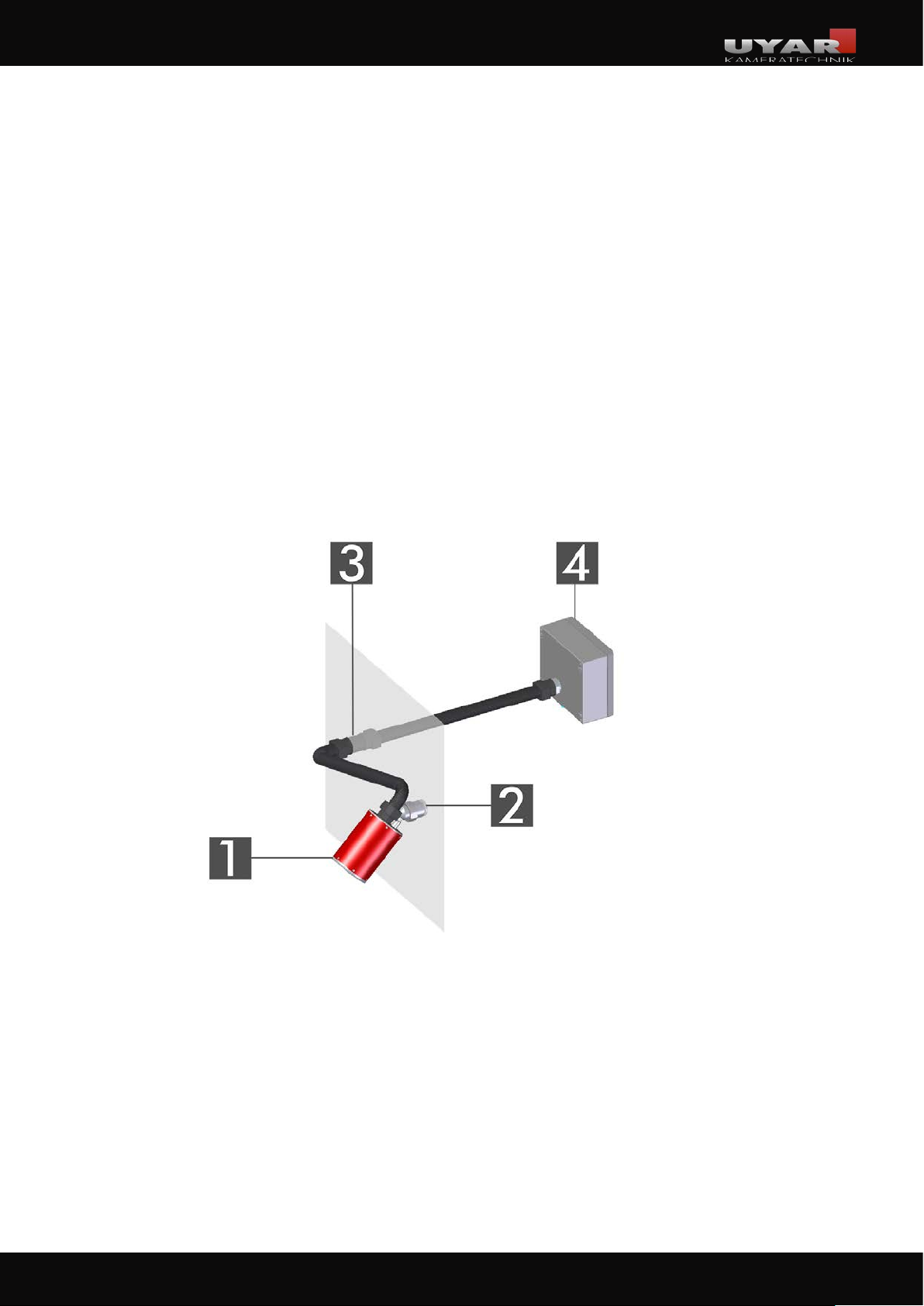
3�2�1 Mounting the camera with external ball joint
1. camera
2. external ball joint
3. optional wall bushing „double socket“
4. control box
13
13
Page 14
Operating instructions VisionLine
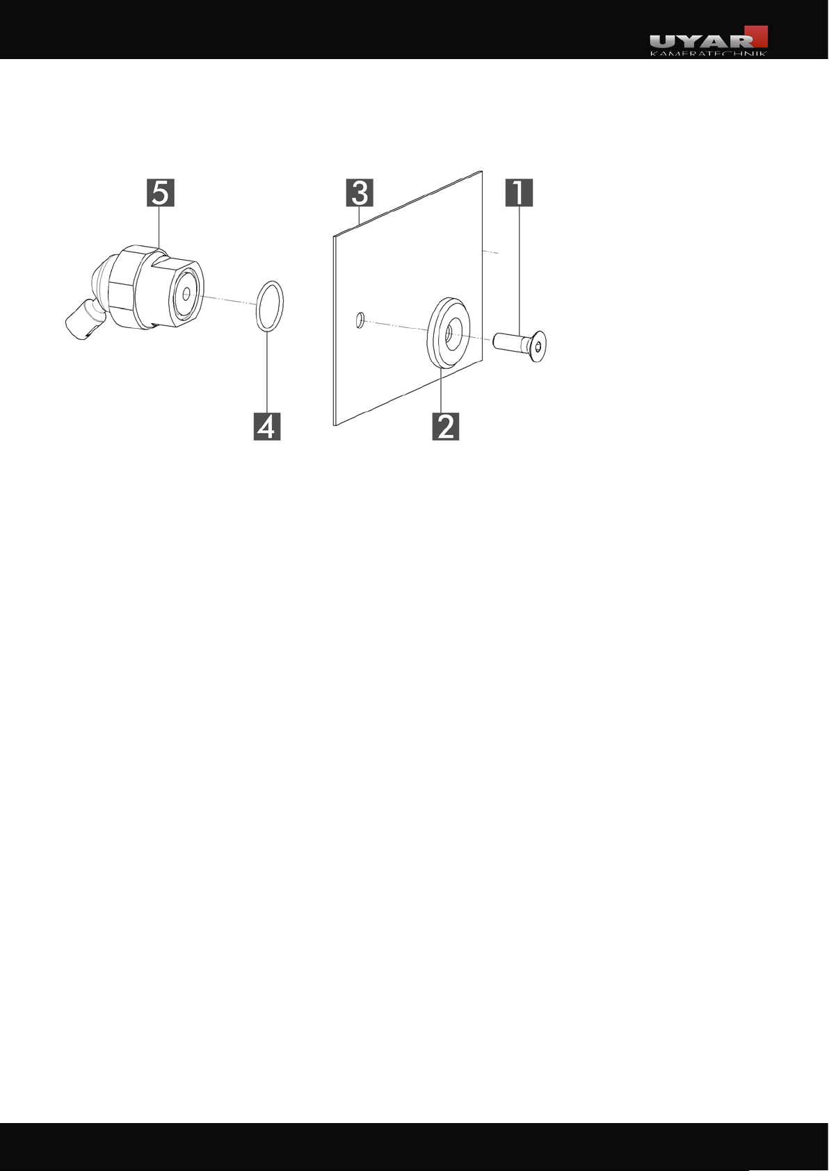
Mounting the camera
1. counter-sunk screw
2. washer
3. machine wall
4. o-ring
5. external ball joint
If you have not purchased a magnetic holder for your camera system, a Ø8.2mm hole is required at the
position specified in Chapter 3.1. Here the camera is attached to the external ball joint (incl. O-ring)
with washer and countersunk screw (included in delivery) according to the above exploded view.
Depending on the length of your cable-hose- package and the position of the control box, there are
now two different steps:
1. The cable-hose- package is led through the machine wall and connected directly to the control
box.
2. The cable-hose- package is separated (section 3.2.5) and with the wall bushing „double
socket“ (section 3.2.4) led through the machine wall. With this variantion, the control box can be
freely positioned and fastened.
14
14
Page 15
Operating instructions VisionLine
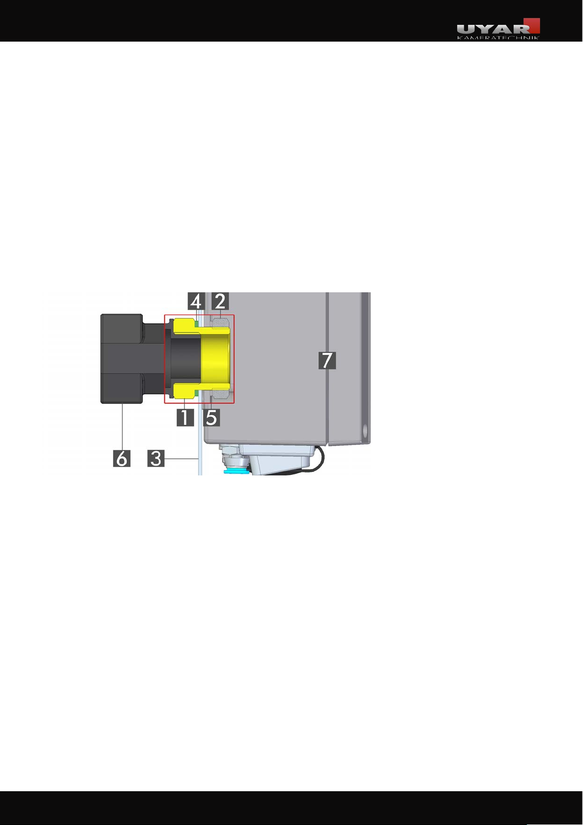
Mounting of the control box via the cable-hose-package:
At the chosen position a Ø30mm hole is needed in the machine wall. This should preferably be done
with a step drill or a sheet metal punch.
Carry the wall mount (no. 1) with the attached flat seal (no. 4) from the interior of the machine
through the hole. On the outside of the machine, the control box (no. 7) must now be placed on the
wall mount (no. 1) and tightened with a washer (no. 5) and the nut (no. 2).
The control box must be aligned with the connections in such a way that the hose and cable are
optimally routed.
The hose connector (no. 6) can now be screwed into the thread of the wall mounting (no. 1) in the
machine interior.
1. wall mount
2. nut M30x1,5
3. machine wall
4. flat seal
5. washer
6. hose connector
7. control box
15
15
Page 16
Operating instructions VisionLine
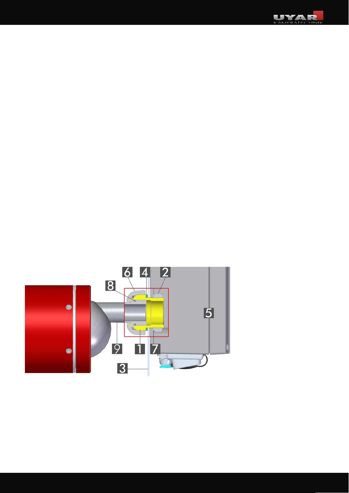
3�2�2 Direct wall mounting with integrated ball joint without hose assembly
Preparations on the machine tool:
At the chosen position a Ø30mm hole is needed in the machine wall. This should preferably be done
with a step drill or a sheet metal punch.
Installation of the control box:
Carry the wall mount (no. 1) with the attached flat seal (no. 4) from the interior of the machine through
the hole. On the outside of the machine, the control box (no. 5) must now be placed on the wall mount
(no. 1) and tightened with a washer (no. 7) and the nut (no. 2).
The control box must be aligned with the connections in such a way that the hose and cable are optimally routed.
Installation of the wall mount and the camera:
First guide the cables, which hang out of the connecting sleeve (no. 9) of the camera, through the wall
mount (no. 1) into the control box.
Then push the connecting sleeve (no. 9) with the O-ring (no. 8) into the wall mount (no. 1). In this step,
you can already roughly align the camera. The fine adjustment can be done later via the integrated ball
joint. Fix the camera by tightening the union nut (no.6).
1. wall mount
2. nut M30x1,5
3. machine wall
4. flat seal
5. control box
6. union nut
7. washer
8. o-ring
9. connection sleeve
16
16
Page 17
Operating instructions VisionLine
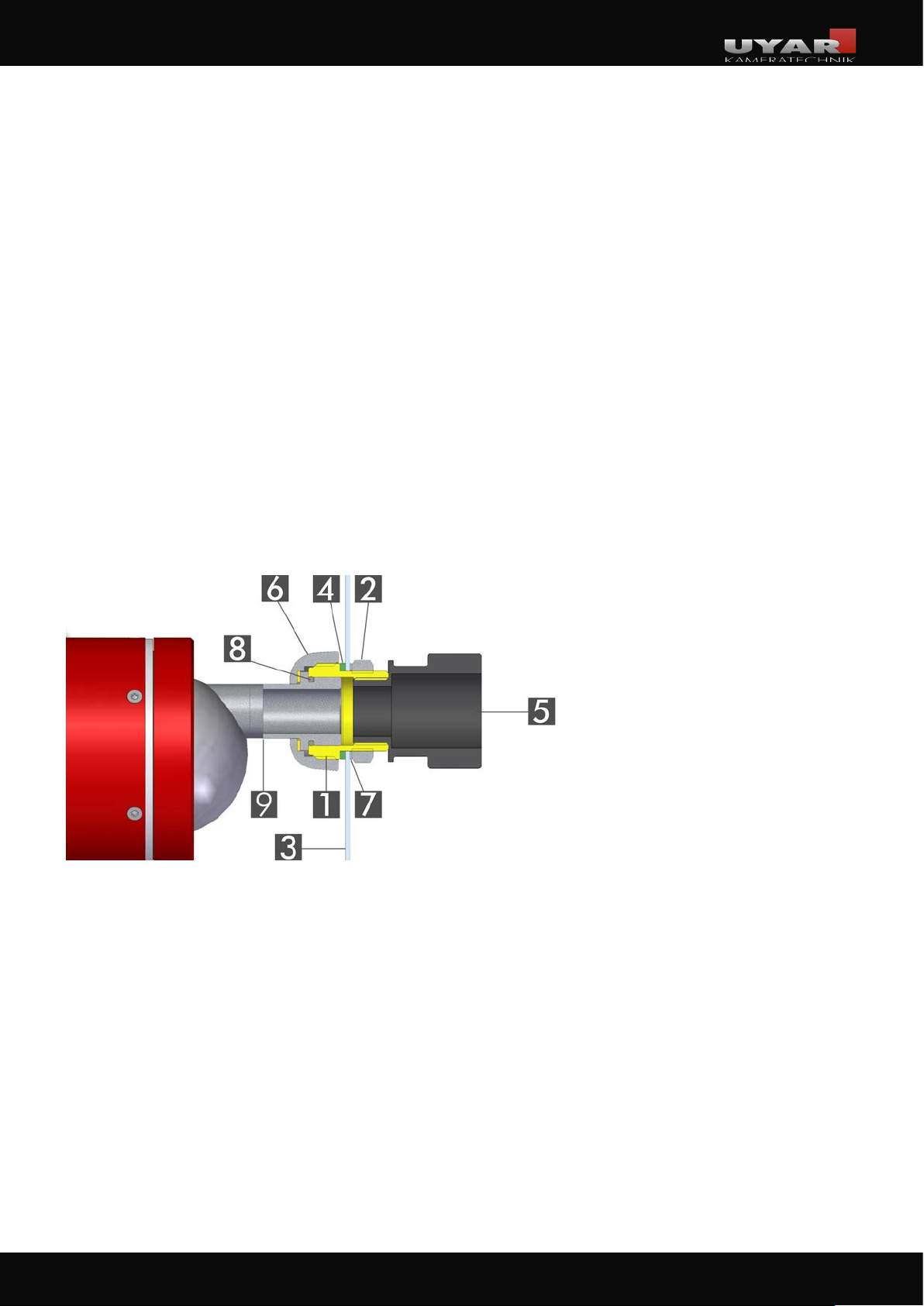
3�2�3 Wall mounting with integrated ball joint and cable-hose-package
Preparations on the machine tool:
At the chosen position a Ø30mm hole is needed in the machine wall. This should preferably be done
with a step drill or a sheet metal punch.
Installation of wall mount, wall connection and camera:
Guide the wall mount (no. 1) with the attached flat seal (no. 4) from the interior of the machine through
the hole. On the outside of the machine, the wall mount must now be tightened with a washer (no. 7)
and the nut (no. 2).
On the outside of the machine, a hose connector (Pos.5) is screwed into the wall mount.
First guide the cables, which hang out of the connecting sleeve (no. 9) of the camera, through the wall
mount (no. 1) into the control box. Then push the connecting sleeve (no. 9) with the O-ring (no. 8) into
the wall mount (no. 1). In this step, you can already roughly align the camera. The fine adjustment can
be done later via the integrated ball joint. Fix the camera by tightening the union nut (no.6).
1. wall mount
2. nut M30x1,5
3. machine wall
4. flat seal
5. hose connector
6. union nut
7. washer
8. o-ring
9. connection sleeve
If you additionally use an optional wall bushing „double socket“ for this installation variant, please
follow the instructions in chapter 3.2.4.
Ideally, you should use the cable duct at the side of the control box for this mounting variant.
You have two optionpossibilities to mountfix the control box:
1. You can use the optionally available magnetic feet for our control box.
2. You attach the control box to your machine with suitable screws.
17
17
Page 18
Operating instructions VisionLine
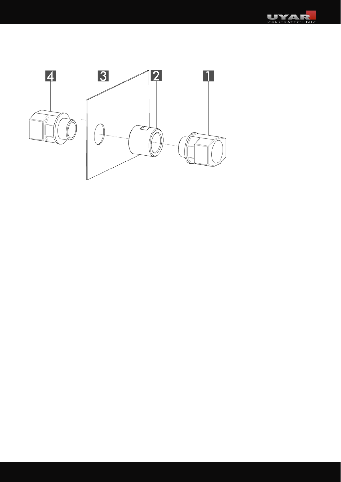
3�2�4 Installation of the optional wall bushing „double socket“
1. hose connector
2. double socket
3. machine wall
4.hose connector
Once the camera is positioned, a suitable position must be found for the wall bushing of the cable-hose -package. Ideally, this should be freely accessible so that the coupling nut can then be tightened with a suitable tool. Furthermore, the position should be determined in such a way that sufficient
space remains outside the machine to position the control box.
At the chosen position a Ø30mm hole is needed in the machine wall (no. 3). This should preferably
be done with a step drill or a sheet metal punch.
Make sure that the contact surfaces on both sides are free of burrs and dirt so that the wall bushing
seals properly. The hose connectors have an integrated sealing lip and do not require any further
sealing elements.
Insert a hose connector (pos. 4) with the thread from the inside of the machine through the hole to
the outside and screw it tight with the double socket (pos. 2). The second hose connector (pos. 1) is
mounted on the other side of the double socket.
Ideally, you should use the side cable duct of the control box for this mounting variant.
You have two possibilities to fix the control box
1. You can use the optionally available magnetic feet for our control box.
2. You attach the control box to your machine with suitable screws.
18
18
Page 19
Operating instructions VisionLine
3�2�5 Hose mounting
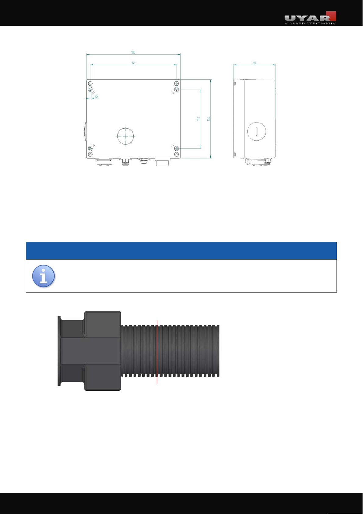
If you are using an optional wall bushing „double socket“ ,you must cut the hose at the suitable position. For this purpose, temporarily lay the hose between the camera and the wall bushing and mark the
separation point. Now carefully cut around the hose with a sharp cutter knife. With the black corrugated
hose, it is important to cut as centrally as possible on the „mountain“ of the corrugated profile.
NOTICE
Do not use scissors for this, as the cable package is guided inside the hose. This must not
be cut under any circumstances.
seaparating line
Disconnect the remaining hose from the cable package and lead it through the wall bushing „double
socket“ and install the hose. This must either be snapped into the hose connector (black corrugated
hose) or fixed with a union nut (black/brown plastic hose).
On the outside of the machine, you must first lead the cable package through the remaining hose again
and into the control box. Then the hose can be mounted on the double socket and the control box as
described above.
19
19
Page 20
Operating instructions VisionLine
3�3 Electrical installation
HAZARD
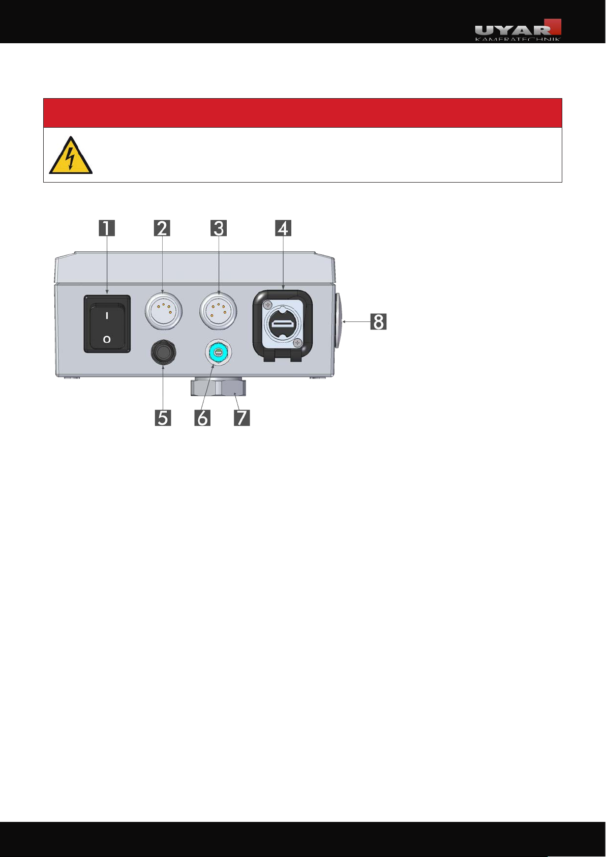
The electrical installation is only permitted by a qualified electrician. Danger due to electric currents!
1. I/O - switch
2. Slot Power connection (AC)
3. Dummy slot
(control unit optional)
4. HDMI output
5. Fine-wire fuse (5x20 T 1.6A)
6. Compressed air inlet (PA6)
7. Cable duct
8. Cable duct (optional)
During the mechanical installation the cables of the camera were already inserted into the control
box. These must now be connected to the (control) electronics of the control box.
Please note the different power connection instructions for the models VisionLine RWC and VisionLine
EAC/EC!
20
20
Page 21
Operating instructions VisionLine
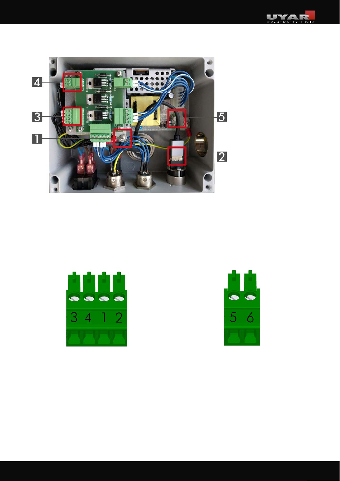
3�3�1 Connect the power connector of VisionLine RWC to the control box board
1. Mounting PE- cable
2. HDMI socket
3. Connector X2 (4-pole)
4. Connector X4 (2-pole)
5. Potentiometer for the
engine Motor speed
First loosen the marked fixing screw (pos. 1) of the upper board and thread the hook eye of the PE
cable under the washer. Tighten the screw again.
The two connectors X2 (4-pole, pos. 3) and X4 (2-pole, pos. 4) must then be connected with the
marked wires as described below:
Connector X2 Connector X4
21
21
Page 22

Operating instructions VisionLine
3�3�2 Connect the power connector of VisionLine EAC/EC to the control box board
1. Connector X2 (2-pole)
2. HDM socket
3. Mounting PE cable
First loosen the marked fixing screw (pos. 3) of the upper board and thread the hook eye of the PE cable
under the washer. Tighten the screw again. Then connect the plug X2 (2-pole, Pos. 1 ) for the power
supply with the socket on the power supply unit in the control box.
3�3�3 Connect the HDMI cable of the camera to the socket in the control box
The HDMI cable coming out of the camera must be connected to the socket (no. 2) in the control box.
Finally close the control box properly!
NOTICE
Make sure that the sealing ring in the cover plate of the control box is not damaged and
is not getting damaged during the installation. Also pay attention that the contact surfaces
on the cover and housing are clean.
22
22
Page 23
Operating instructions VisionLine
3�4 Pneumatic installation
CAUTION
Make sure that the system is not under pressure before starting to work! Risk of injury!
Notice for the Model VisionLine EC:
Since the VisionLine EC model does not need to be supplied with compressed air, a blanking plug is
located in the compressed air inlet of the control box when delivered. This is not allowed to be removed,
otherwise there is a danger of liquid entering the control box.
Mount the air service unit in a suitable place. This must be chosen so that:
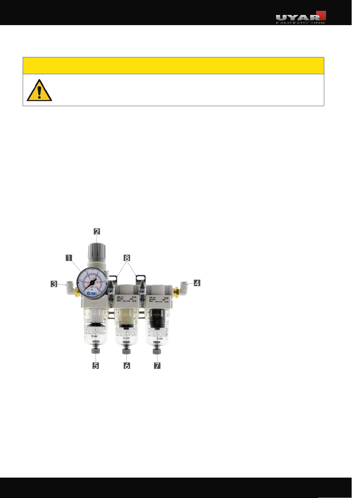
■ the pressure gauge (no.1) of the air service unit is always visible,
■ the pressure regulator (no.2) of the air service unit is freely accessible and movable,
■ all pneumatic lines are not kinked, crushed or otherwise restricted in their function.
1. Pressure gauge
2. Pressure regulator
3. Air service unit input
4. Air service unit output
5. Coarse filter (5 micrometer)
6. Fine filter (>0,3 micrometer)
7. Super fine filter (>0,01 micrometer)
8. Mounting brackets
Connect the output side (no.4) of the air service unit to the control box via a standard pneumatic hose,
type PA6.
Connect the input side (no.3) of the air service unit to your in-house compressed air network with a
standard pneumatic hose.
23
23
Page 24
Operating instructions VisionLine
4 Operation
The camera system is designed for continuous operation and can therefore remain switched on continuously.
NOTICE
During the operation of the machine, it is not allowed to interrupt the compressed air
supply of the camera systems VisionLine RWC and VisionLine EAC.
4�1 Commisioning
CAUTION
Commissioning is only authorized by qualified personnel. During commissioning there is
a risk of starting or rotating parts. Avoid contact during the operation.
When the assembly has been successfully completed, commissioning can begin.
■ First pressurize the system with compressed air: Set the air service unit via the pressure regulator
so that the pressure gauge shows a pressure of approx. 0.3 to 0.5 bar.
■ Make sure that both, the control box and the playback device, are connected to the power supply.
■ Connect the control box and a suitable playback device (with the HDMI input) by plugging an
HDMI cable into the appropriate ports of the respective devices. Make sure the HDMI connector
on the control box snaps into place.
■ Now switch on the playback device: probably you have to set the signal input to „HDMI“ on
themonitor. Instructions for this are provided by the manufacturer of the playback device you are
using.
■ Now switch on the camera system: To do this, set the rocker switch on the bottom of the control
box to „I“.
■ After powering up the system on the control box, it may take up to 30 seconds before the first
footage is transferred to your monitor.
Please observe the following notes when using the optional operating unit:
If you have performed all of the steps listed above for commissioning, you must also make sure,
when that the key switch „Maintenance“ on the operating unit is in the „on“ position, when using an
operating unit.
The control unit also gives you the option of turning the integrated power LEDs on or off as needed.
To do this, press the „Lighting on / off“ push-button on the operating unit. After turning on the switch,
the power LEDs in the camera body light up and the switch is highlighted with a green light.
The optional control unit is only available for the VisionLine RWC camera system.
24
24
Page 25

Operating instructions VisionLine
NOTICE
The key-operated switch „Maintenance“ must not be turned „off“ during machine operation. This switch position is only for maintenance or when using the separately available
protection cap.
Your new UYAR camera system is now ready for use!
4�2 Control
After the successful commissioning, your camera system is already running in operating mode. Since
our components are designed for continuous operation, you only have to turn off the camera for maintenance.
To do this, press the on/off switch on the control box.
Users with an optional operating unit also have the option to deactivate the system using the “Maintenance” key-operated switch. In addition, the LED lamps can be switched on and off separately with
the operating unit.
The VisionLine RWC model can be temporarily taken out of service and still remain in the running machine tool.
■ First switch off the camera system as described above.
■ Once this has been done, the compressed air supply can also be turned off via the regulator of
the air service unit.
■ As soon as the disc no longer rotates and the compressed air supply has been interrupted, it is
absolutely necessary to push the protective cap included in the scope of supply onto the camera
housing from the front.
NOTICE
As soon as the protective cap is removed from the camera housing of VisionLine RWC
and the machine tool is put into operation, it is essential to ensure a constant supply of
compressed air!
Since the VisionLine EAC model does not have a protective cap, a permanent supply of
compressed air is absolutely essential. So do not forget to turn on the compressed air at
the air service unit again to the intended working pressure.
25
25
Page 26
Operating instructions VisionLine
4�3 Maintenance / Servicing
Of particular importance is the regular check for contamination and if necessary the prompt and thorough cleaning. Only with regular care and cleaning the trouble-free and permanent operation of UYAR
camera systems is possible.
With our special glass panes, which are installed in all models of the VisionLine RWC, you have acquired a low-maintenance and robust product that makes it easy to clean or even change the special glass
pane.
Different concentrations of cooling lubricants, aluminum processing and changing minimum lubrication, may have a negative impact on the visibility of the disc due to coating.
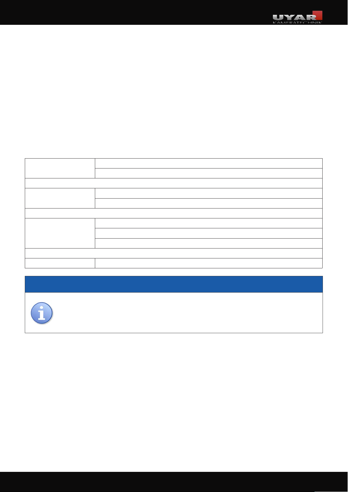
daily Checking the pane for damage
Cleaning the pane of glass
weekly Check the hose system for leaks
Check operating pressure at pressure gauge
monthly Checking the camera mount for loosened screw connections
Checking the monitor holder for loosened screw connections
Checking the filter elements of the air service unit
if required Replacing the filter elements of the air service unit
NOTICE
For a permanently good view on the process and optimal production conditions, we recommend holding an interchangeable glas pane and inserting and cleaning it alternately.
The special glass pane is a wearing part. A contamination and damage by chips on the
glas pane does not constitute a reason for complaint.
26
26
Page 27
Operating instructions VisionLine
4�3�1 Changing the special glass pane
The special glass panes of our cameras are extremely robust and designed for continuous operation
under the influence of cooling lubricantslant and metal chips.
Nevertheless, the special glass pane is a spare or wear part on all models. The, permanent operation
of cooling lubricants and metal chip bombardmentwhich can lead to deposits, scratches or other
defects. The glas pane of all models can be changed in a few easy steps.
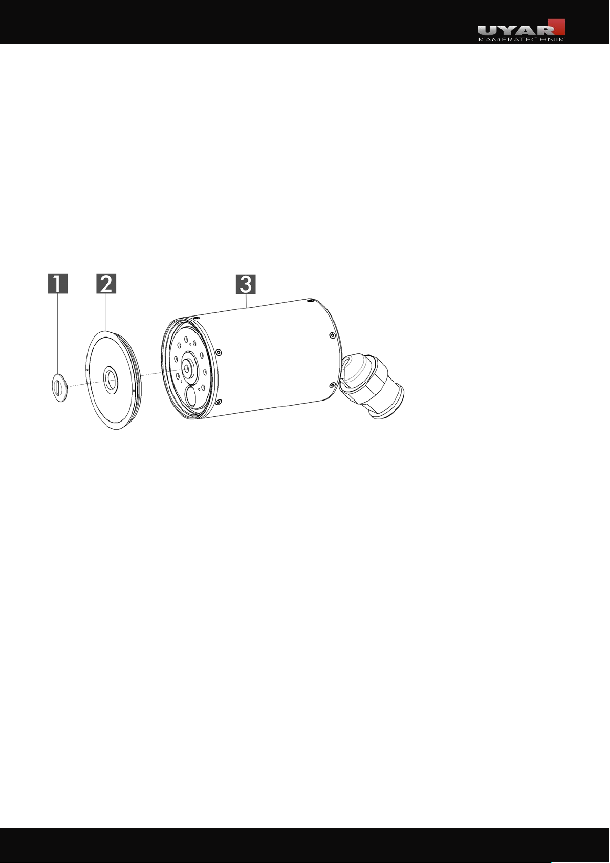
Pane change VisionLine RWC
1. Clamping Screw
2. Special glass pane
3. Camera housing RWC
Loosen the clamping screw (pos. 1). To do this, fix the pane (pos. 2) in place with the aid of a
face spanner over the two holes in the outer ring. Then pull the pane forward from the mount and
place the new pane on top. Tighten the new pane in the same way as you removed the old pane.
27
27
Page 28
Operating instructions VisionLine
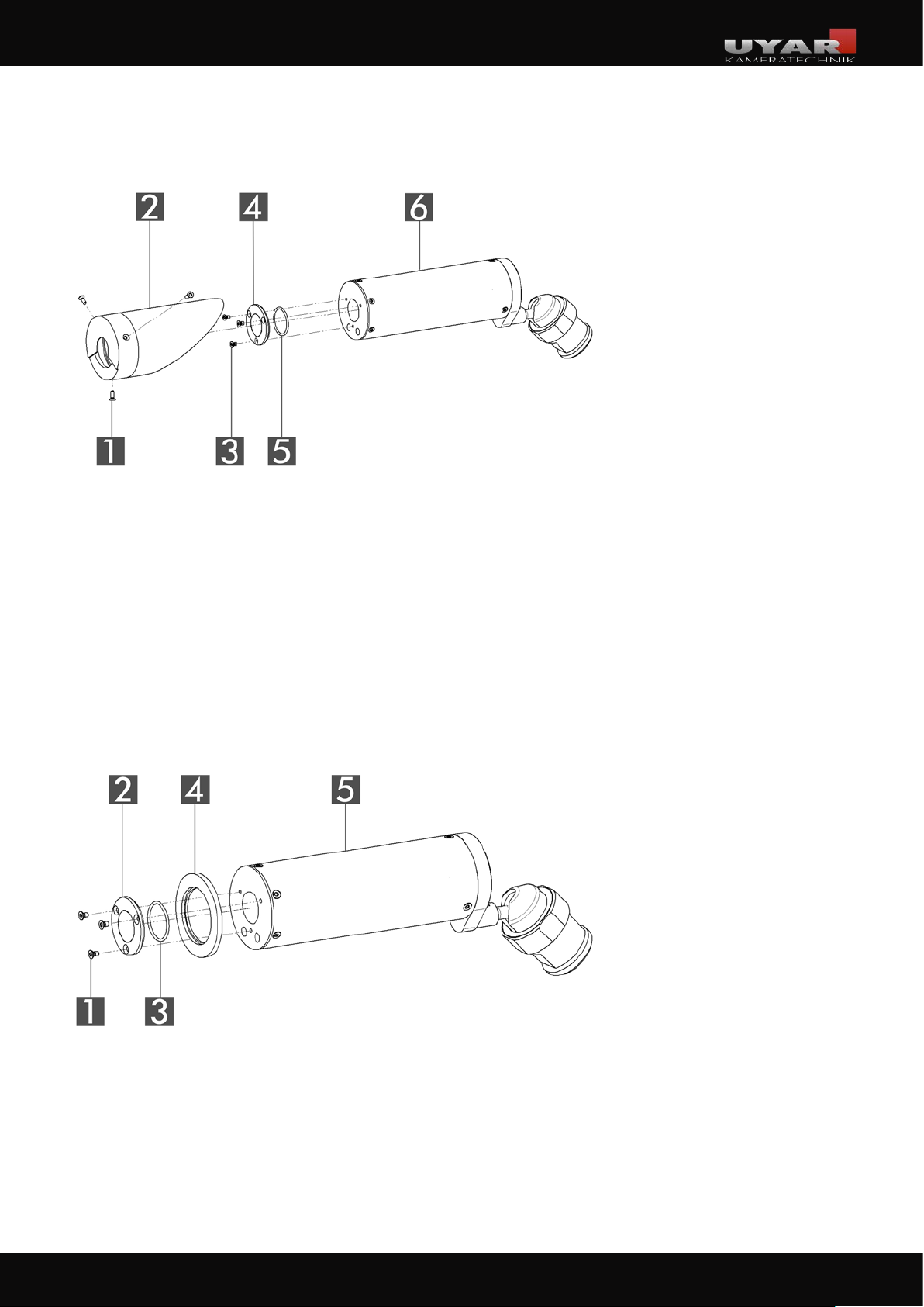
Pane change VisionLine EAC
1. Countersunk screw M3x8
2. Air attachment
3. Countersunk screw M3x5
4. Special glass pane
5. O-ring
6. Camera housing EAC
First loosen the three countersunk screws (pos. 1) from the air attachment (pos. 2).
Then remove it from the camera housing (pos. 6). Three further countersunk screws (pos. 3) must be
loosened on the face side so that the pane (pos. 4) with holder can be loosened. Replace both the
pane and the supplied O-ring (pos. 5) behind the pane. First tighten the three countersunk screws
(pos. 3) on the front, then mount the air attachment.
Pane change VisionLine EC
1. Countersunk screw M3x5
2. Special glass pane
3. O-ring
4. Outer ring
5. Camera housing EC
Loosen the three countersunk screws (pos. 1) and remove the pane (pos. 2) incl. outer ring (pos. 4).
Replace both the pane (pos. 2) and the supplied O-ring (pos. 3) behind the pane. Then mount the
new pane including outer ring (pos. 4) and tighten the three countersunk screws (pos. 1) on the face
side.
28
28
Page 29
Operating instructions VisionLine
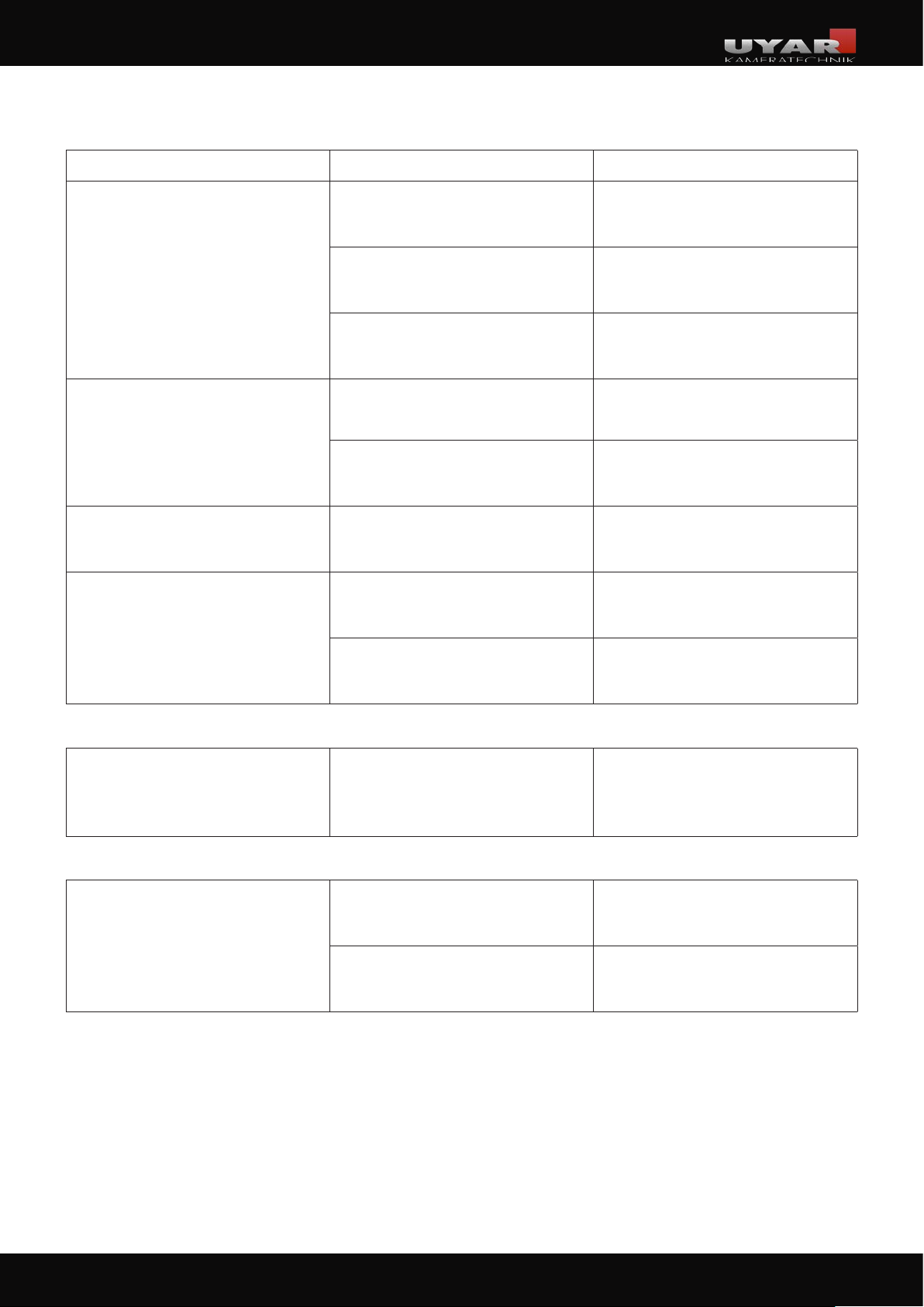
4�4 Error diagnostics
Disturbance / error Reason Remedy
Rocker switch is in position „I“:
System still remains out of service
Pressure regualtor is open, but no
compressed air flows
Compressed air does not flow
consistent during operation
Camera is switched on, but no
picture appears on the monitor
Power supply provided by
costumer is out of service
Put power supply into operation
Power supply not connected Connect plug
Fuse damaged / triggered Change the fuse
Supply line provided by customer
is kinked
Compressed air is not switched on
Switching behaviour of the compressed
air does not fit the system
HDMI cable is not connected
Monitor is not switched on /
connected
Renew the hose and secure it against
kinking
2
Check switching behaviour and change
if necessary
2
Check switching behaviour and change
if necessary
2
Connect HDMI cable. Pay attention
to directional cables.
Switch on the monitor
1
VisionLine RWC
On the displayed picture a „swimming“
occurs
Frequency of the machine LED and
rotation of the special glass pane
superimpose each other
VisionLine EAC
Compressed air leakage within
the camera system
Pane is too slowly cleared of coolant
Set pressure is too low Increase pressure at pressure gauge
1 Disconnect before starting the repair. Observe safety rules!
2 Switch off the compressed air before starting the repair.
Slightly increase the speed of the motor.
See chap. 4.4.1 (Pitcure of the control
box with marked potentiometer)
Check camera system for leakage
and replace defective parts
29
29
Page 30
Operating instructions VisionLine
4�4�1 Adjusting the engine speed of the rotary pane
In some machines, strong LED lighting can cause the image to „float“. This is shown by the fact that
the image on the monitor looks as if the surface is like undulating water. If the camera is moved several
times in a machine and the angle of incidence of the machine LED changes, the problem can also occur
again after previous speed regulation. To solve the problem there is a small potentiometer on the power
supply of the control box to regulate the engine speed.
See the picture in chapter 3.3.1 for this. The plastic potentiometer must be turned slightly clockwise (to
increase the speed) or counterclockwise (to reduce the speed) with a screwdriver.
Finally close the control box properly!
If the disturbances cannot be remedied by the listed steps or repeat frequently, please contact directly:
A.U. Uyar Technology Center e.K.
Carl-Bosch-Straße 6
33790 Halle (Westf.)
Germany
Phone: +49 (0) 5201 - 97 180 - 0
4�5 Decomissioning / Disposal
According to the WEEE (Waste of Electrical and Electronic Equipment) guideline electronic and electrical devices does not belong into the household waste. This product and its
components must be recycled or disposed separately. The consumer obliges to dispose the
product in accordance with the legal regulations.
5 Appendix
30
30
 Loading...