

Page 1

Operating Manual
SWISS MADE BY UWATEC AG
®
Smart TEC
English
Page 2
2
Safety considerations
I UWATEC®Smart dive computers
You must carefully read and understand this entire manual before using your Smart TEC.
Diving has many inherent risks. Even if you follow the instructions of this
manual in a careful manner, it is still possible that you may be seriously injured
or die from decompression sickness, oxygen toxicity or some other inherent
risk of scuba with Nitrox or compressed air. Unless you are fully aware of these
risks and are willing to personally accept and assume responsibility for those
risks, do not use Smart TEC!
Guidelines for the use of Smart TEC:
The following guidelines for using Smart TEC are derived from the latest medical research and the
recommendations of the American Academy of Underwater Sciences for diving with diving computers.
Following these guidelines will greatly increase your safety while diving, but cannot guarantee that
decompression sickness or oxygen toxicity will not occur.
• Smart TEC is designed for dives with Nitrox (to a max.100% O
2
) and compressed air (21%O2) only. Do
not use Smart TEC for dives made with other mixed gases.
• It is absolutely necessary to check the set mixture before each dive and to compare it to the gas mixture currently used. Always remember: setting an incorrect mixture carries an inherent risk of decompression sickness and/or oxygen toxicity! Maximum deviation from the measured mixture must not
exceed 1% O
2
. An incorrect gas mixture can be lethal!
• Only use Smart TEC with open circuit breathing systems. The gas mixture must be determined for each
pressure tank you use.
• Only use Smart TEC for diving with an independent breathing apparatus. Smart TEC is not designed
for long term exposures with Nitrox.
• Always observe the visual and audible alarm signals of Smart TEC. Avoid situations of increased risk
which are marked with a warning sign in this operating manual.
• If the ascent arrow appears, start to ascend.
• If the flashing ascent arrow appears, start to ascend immediately.
• Smart TEC has a ppO
2
warning, the default limits of which are set at 1.4 bar ppO2max. This limit can
be adjusted via SmartTRAK. An alteration of the ppO2max to higher than 1.6 bar is dangerous and we
do not recommend this.
• Frequently check the "oxygen clock" (CNS O
2
Limit), especially in the range higher than 1.4 bar ppO2.
Ascend and finish the dive if the CNS O2exceeds 75%.
• Never dive deeper than the Maximum Operating Depth (MOD) pertinent to the gas mixture in use.
• Always check the diving limits considering the oxygen content and standard sports diving procedures
(decompression sickness, oxygen toxicity).
• In accordance with the recommended maximum diving limit of all instructional agencies, do not dive
deeper than 40 metres/130 feet.
•
The danger of nitrogen narcosis has to be taken into consideration
. Smart TEC gives no warning about
this.
• On all dives with Smart TEC, make a safety stop for at least 3 minutes at 5 metres (15 feet).
• All divers using dive computers to plan dives and indicate or determine decompression status must use
their own computer, which they take with them on all dives.
• If Smart TEC fails at any time during the dive, the dive must be terminated, and appropriate surfacing
procedures (including a slow ascent and a 3 to 5 minute safety stop at 5
metres /15 ft
) should be initia-
ted immediately.
• Comply with the ascent rate and carry out any decompression stop required. If the computer should
fail for any reason, you must ascend at a rate of 10m (30 feet) per minute or less.
• On any given dive, both divers in a buddy pair must follow the most conservative dive computer for
that particular dive.
• Never dive without a buddy. Smart TEC does not substitute for a dive buddy.
• Only make dives that are appropriate to your level of dive training. Smart TEC does not increase your
knowledge of diving.
WARNING
Page 3
English
3
Safety considerations
I UWATEC®Smart dive computers
I
• Always dive with back-up instruments. Make sure that you always use back-up instrumentation including a depth gauge, submersible pressure gauge, digital bottom timer or dive watch, and have access
to decompression tables whenever diving with a dive computer.
• Avoid repeated ascents and descents (yo yo diving).
• Avoid repeated heavy workload while at depth.
• Plan the dives to be shorter if they are made in cold water.
• After finishing the decompression or at the end of a no-stop dive, the final stage of the ascent should
be as slow as possible.
• You MUST be familiar with all signs and symptoms of decompression sickness before using Smart TEC!
Seek IMMEDIATE treatment for decompression sickness should any of these signs or symptoms occur
after a dive! There is a direct correlation between the effectiveness of treatment and the delay between the onset of symptoms and the treatment for decompression sickness.
• Only dive with Nitrox after you have been thoroughly instructed by a recognised institution.
Repetitive dives
• Do not start your next dive before your CNS O
2
% status has dropped below 40%.
• Diving with Nitrox: Make sure your surface interval is long enough (just like diving with compressed
air). Plan for a minimum surface interval of two hours. Oxygen, too, needs sufficient time to leave
the body.
• Match gas mixture to the intended dive.
• Do not attempt a repetitive dive if the microbubble warning is visible on the display.
• Plan a day without diving once a week.
• If you have to change computers, wait at least 48 hours before carrying out your next dive.
Altitude and diving
• Do not dive at altitudes higher than 4000m (13000 feet).
• After a dive do not rise to altitudes that Smart TEC prohibits via the flashing altitude
segments. (->25)
Flying after diving
• After diving, wait at least 24 hours prior to flying.
NO
Smart TEC dive instrument is a personal protective equipment in compliance with the essential safety
requirements of the European Union directive 89/686/EEC. RINA SpA, Via Corsica 12, I-16128 Genoa,
notified body no. 0474, have certified the conformity with the European Standard EN 250:2000 and EN
13319:2000.
EN250:2000 Respiratory equipment - Open circuit self contained compressed air diving apparatus Requirements, testing, marking (pressure gauge test).
EN13319:2000 Diving accessories - Depth gauges and combined depth and time measuring devices Functional and safety requirements, test methods. Any information on decompression obligation displayed by equipment covered by this standard is explicitly excluded from its scope.
Page 4
4
Introduction
I UWATEC®Smart dive computers
The following symbols are used in the operating manual:
This operating manual makes use of the following icons to indicate especially important comments:
Remarks Information and tips which are important for optimal use of the functions of
Smart TEC.
Danger!
– + E
B
Bridge contacts
Example: bridging contacts B and E
Instructions for manual input
Flashing display
Audible attention
signal
Audible signals
September 2004, Copyright©by UWATEC Switzerland
4 sec.
Audible alarm signal
Valid only for dives
with more than one
gas mixture
Page reference
e.g. ->10
Important remarks concerning signal words and symbols
Congratulations on purchasing Smart TEC and welcome to UWATEC. From now on you will enjoy the assistance of the most extraordinary dive computer - equipped with UWATEC's most innovative technology while diving.
Smart TEC enables you to use up to three different gas mixtures during the same dive. However,
for an easy reading this manual mainly refers to dives with a single gas mixture. Information for diving with
several gas mixtures is marked with ( ) or has been summarised in special chapters.
We thank you for choosing Smart TEC and we hope you will enjoy safe dives in the future!
Further information on UWATEC Smart dive computers and other products by UWATEC can be found on
our web page at www.uwatec.com.
To make this manual easier to read we will use the term 'TEC' as an abbreviation for 'UWATEC Smart TEC
diving computer' throughout this booklet.
Safety considerations
Dive computers provide divers with data; they, however, do not provide the knowledge how this data
should be understood and applied. Dive computers cannot replace common sense! You must therefore
carefully read and understand this entire manual before using your TEC.
->
Push buttons
Press or press and hold (->9)
e.g. press the upper left button
Indicates a potentially hazardous situation which, if not avoided, could result
in death or serious injury.
WARNING
Page 5
English
5
Quick reference
I UWATEC®Smart dive computers
I
%
Logbook
39
Dive planner
Battery capacity
10
37
O2 mix
18
Microbubble level
28
Exit (2 sec.)
Exit
Confirmation
Confirmation
%
Switching on
10
+
–
Gauge mode
26
Confirmation
+
–
Navigation
Display
switched off
%
NO STOP
%
%
Bottom time
+
–
Surface
interval
+
–
()
Percentage
of oxygen
Microbubble
level
Gauge mode
on and off
+
–
Maximum
operating
depth (MOD)
+
–
Dive number
+
–
NO
NO
%
DECO
STOP
NO STOP
LEVELSTOP
CNS O2%
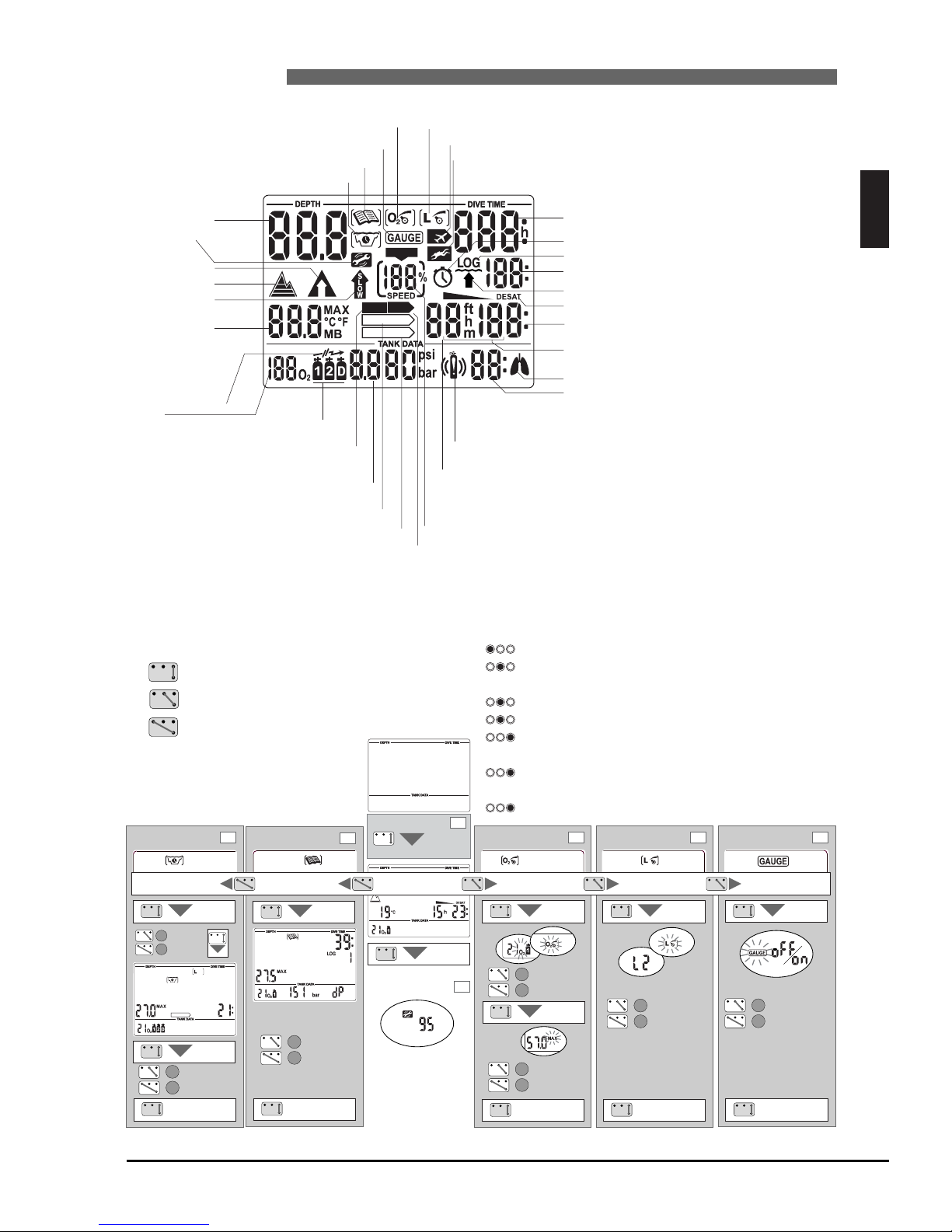
Dive planner icon
Logbook icon
Microbubble level icon (input / MB level reduced)
O
2 mix icon (input)
Current depth
Altitude sections
Ascent obligation
Too fast ascent
Maximum depth
Temperature
Microbubble level
Maximum Operating
Depth (MOD)
Service icon
Do not fly Icon
Dive time / No-fly time / SOS duration
Oxygen toxicity CNSO
2
Ascent rate
Battery capacity
Desaturation time indicator
Desaturation duration / Duration of surface interval
Total ascent time / Dive number
Increased workload warning
Transmitter warning
Remaining bottom time RBT / Number of active tanks
Decompression depth / Level stop depth
No-stop time / Decompression duration / MB no-stop time
Level stop duration / Duration of Microbubble Warning
Tank pressure / Gas consumed
Partial pressure of oxygen ppO
2
Logbook indicator
Ascent time icon
No-stop indicator
Level stop indicator
Decompression stop obligation
Ignored decompression stop
Tank pressure warning
At the surface: several gas mixture have been set
Decompression stop indicator
Gauge icon
Icon for stopwatch and safety stop
Tank icons
Do not dive icon
Microbubble warning
O2 mix
Start / Confirmation / Enter
+ / Navigate
– / Navigate
Display switches off automatically after 3 minutes without operation.
Operating scheme
Select (press) and confirm (press and hold) gas mixtures
Activate the timer for safety stops (dive mode only, in
depths < 6.5 m / 20 ft)
(press)
Operate the stopwatch (gauge mode only) (press)
Set a bookmark (press)
Toggle between maximum depth > temperature >
MB level > …(press)
Intermediate time and reset (in gauge mode only and
while stopwatch is active) (press)
Switching on the backlight (press and hold)
Page 6

I Safety considerations ___________________________________2
Introduction ___________________________________4
Important remarks concerning signal words
and symbols ___________________________________4
Quick reference / Operating scheme ___________________________________5
List of chapters ___________________________________6
II System and operation ___________________________________8
1 System description ___________________________________8
2 Operation ___________________________________8
2.1 Operating elements ___________________________________8
2.2 SmartTRAK ___________________________________9
2.3 Switching on the display __________________________________10
2.4 Checking the battery capacity __________________________________10
2.5 Selection and activation of user functions __________________________________10
2.6 Active backlight __________________________________11
2.7 Switching off the display __________________________________11
3 SOS mode __________________________________11
4 Setting up Smart TEC __________________________________12
4.1 Mounting of transmitter __________________________________12
4.2 Pairing of transmitter and dive computer __________________________________13
III Diving with Smart TEC __________________________________15
1 Terminology / Symbols __________________________________15
1.1 General terminology / Display during no-stop phase __________________________________15
1.2 Display during decompression phase /
Remaining Bottom Time __________________________________15
1.3 Nitrox information (
O2information) __________________________________16
2 Attention messages and alarms __________________________________17
2.1 Attention messages __________________________________17
2.2 Alarms __________________________________17
3 Preparation for the dive __________________________________18
3.1 Setting the gas mixture and MOD __________________________________18
3.2 Setting the MB level __________________________________18
3.3 Preparation for diving with more than one gas mixture ________________________________18
3.4 Preparation for the dive and function check __________________________________18
4 Functions during the dive __________________________________19
4.1 Immersion __________________________________19
4.2 Setting bookmarks __________________________________19
4.3 Dive time __________________________________19
4.4 Current depth __________________________________19
4.5 Maximum depth / Temperature __________________________________19
4.6 Ascent rate __________________________________19
4.7 Partial pressure of oxygen (pp
O
2
) / Maximum Operating Depth (MOD) ___________________20
4.8 Oxygen toxicity (CNS
O2%) __________________________________21
4.9 Tank pressure __________________________________21
4.10 Remaining Bottom Time (RBT) __________________________________22
4.11 Decompression information __________________________________22
4.12 Safety stop timer __________________________________23
5 Functions at the surface __________________________________24
5.1 End of a dive __________________________________24
5.2 Desaturation time __________________________________24
5.3 No-fly time __________________________________24
5.4 Microbubble warning __________________________________24
6
List of chapters
I UWATEC®Smart dive computers
Page 7

English
7
List of chapters
I UWATEC®Smart dive computers
I
6 Diving in mountain lakes __________________________________25
6.1 Altitude ranges __________________________________25
6.2 Prohibited altitude __________________________________25
6.3 Decompression dives in mountain lakes __________________________________25
IV Gauge mode __________________________________26
V Diving with microbubble levels (MB) __________________________________28
1 Comparison of dives with MB level L0 and MB level L5 __________________________________28
2 Terminology __________________________________29
2.1 Display during microbubble (MB) no-stop phase __________________________________29
2.2 Display during level stop phase __________________________________29
3 Preparation for a dive with microbubble levels (MB levels) __________________________________30
3.1 Setting the MB level __________________________________30
4 Functions during the dive with microbubble levels __________________________________30
4.1 Level stop information __________________________________30
4.2 Total time of ascent __________________________________31
4.3 Decompression obligation __________________________________31
4.4 Level stop and deco stop __________________________________32
5 Complete a dive with MB levels __________________________________32
VI Diving with more than one gas mixture __________________________________32
VII Dive planner __________________________________37
1 Planning a no-stop dive __________________________________37
2 Planning a decompression dive __________________________________38
3 Leaving the dive planner __________________________________38
VIII
Logbook __________________________________39
1 Survey __________________________________39
2 Operation __________________________________39
IX Appendix __________________________________40
1 Technical information __________________________________40
2 Maintenance __________________________________40
2.1 Replacing the battery of the transmitter __________________________________40
3 Conversion of tank pressure __________________________________42
4 Warranty __________________________________42
5 FCC __________________________________43
6 Index __________________________________43
Page 8
8
II System and operation
II UWATEC®Smart dive computers
1 System description
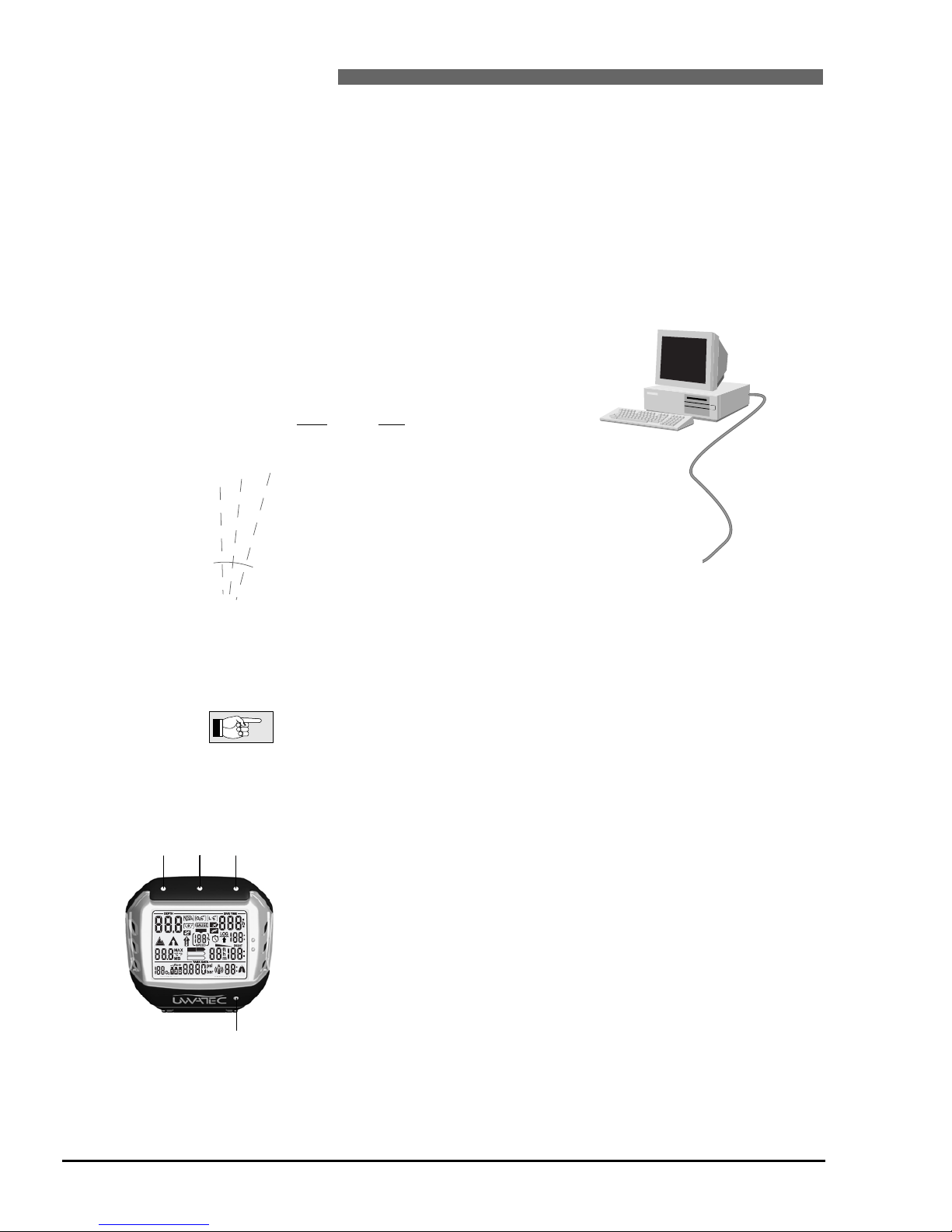
TEC displays all important dive and decompression data and comes with a unique multichannel receiver,
which can receive tank pressure data from up to 3 transmitters. Each transmitter is mounted at the high
pressure (HP) outlet of the regulator, where it measures the tank pressure and radio transmits the information to TEC. UWATEC's specially patented transmission process prevents interference and ensures continuous and reliable reception
TEC has a data memory which stores the dive data. The data can be transmitted with an infrared interface (IrDA) and the SmartTRAK software to a Windows
®
personal computer.
The SmartTRAK CD software is included with the TEC Package. Infrared interfaces are available in PC stores. A list of recommended interfaces is available on the UWATEC homepage (www.uwatec.com).
2 Operation
On page 5 you will find an operating schematic.
2.1 Operating elements
TEC has 4 operating contacts B, E, +, – on the outside of the housing. For
manual operation, touch base contact B and any one of the other three contacts above the display with moistened fingers («bridging» contacts).
Contact B: Base contact, which has to be touched for all operations.
Contact E: Enter contact. It serves to switch on TEC and to confirm or enter the
displayed value. It is therefore comparable to the ENTER or RETURN key of a
keyboard.
+ / – Contacts: These allow to navigate between menus and, once inside a
menu, to increase or decrease the indicated value.
Smart TEC
Pressure transmitter
Infrared Interface
(option)
SmartTRAK
Contacts
-+E
B
NO
NO
%
DECO
STOP
NO STOP
LEVELSTOP
CNS O2%
Infrared port
Page 9

9
II System and operation
II UWATEC®Smart dive computers
To use the push buttons TEC must be switched on. Operation of the push
buttons is divided into «press» and «press and hold (1 second)».
The push buttons , and activate the following functions:
Select the gas mixture (press)
Confirm the gas mixture (press and hold)
Activate the timer for safety stops (dive mode only, in depths < 6.5 m /
20 ft) (press)
Operate the stopwatch (gauge mode only) (press)
Set a bookmark (press)
Toggle between maximum depth > temperature > MB level > …
(press)
Intermediate time and reset (in gauge mode only and while stopwatch is active) (press)
Switching on the backlight (press and hold)
2.2 SmartTRAK
With SmartTRAK you can transfer dive data to a personal computer and graphically display the data.
The following settings may be changed with SmartTRAK:
• Unit system metric/imperial
• Audible attention signal suppression selective
• Gauge mode
• Depth alarm 5 - 100 m (20 - 330 feet)
• Backlight illumination duration 2-12 sec.
• Maximum partial pressure of oxygen (ppO
2 max
) 1-1.95 bar
• Time limit to reset the O2% mix to air no reset / 1 - 48 hrs.
• Minimum reserve pressure at the end
of the dive (basis for RBT calculation) 20 – 120 bar (300 - 1750 psi)
• Tank pressure alarm 50 - 200 bar (750 - 2900 psi)
• Replace audible RBT alarm by audible attention signal
• Workload sensitivity 25 steps
• Safety stop duration 1-5 min.
The following data may be recalled with SmartTRAK:
• Number of past dives
• Total duration of past dives
• Atmospheric pressure
• Pairing information from up to 3 transmitters
• Dive profile
• Logbook
• Temperature curve
• Workload curve
• Alarms and attention messages
• Bookmarks
II
English
Push buttons
Page 10
10
II UWATEC®Smart dive computers
2 Operation
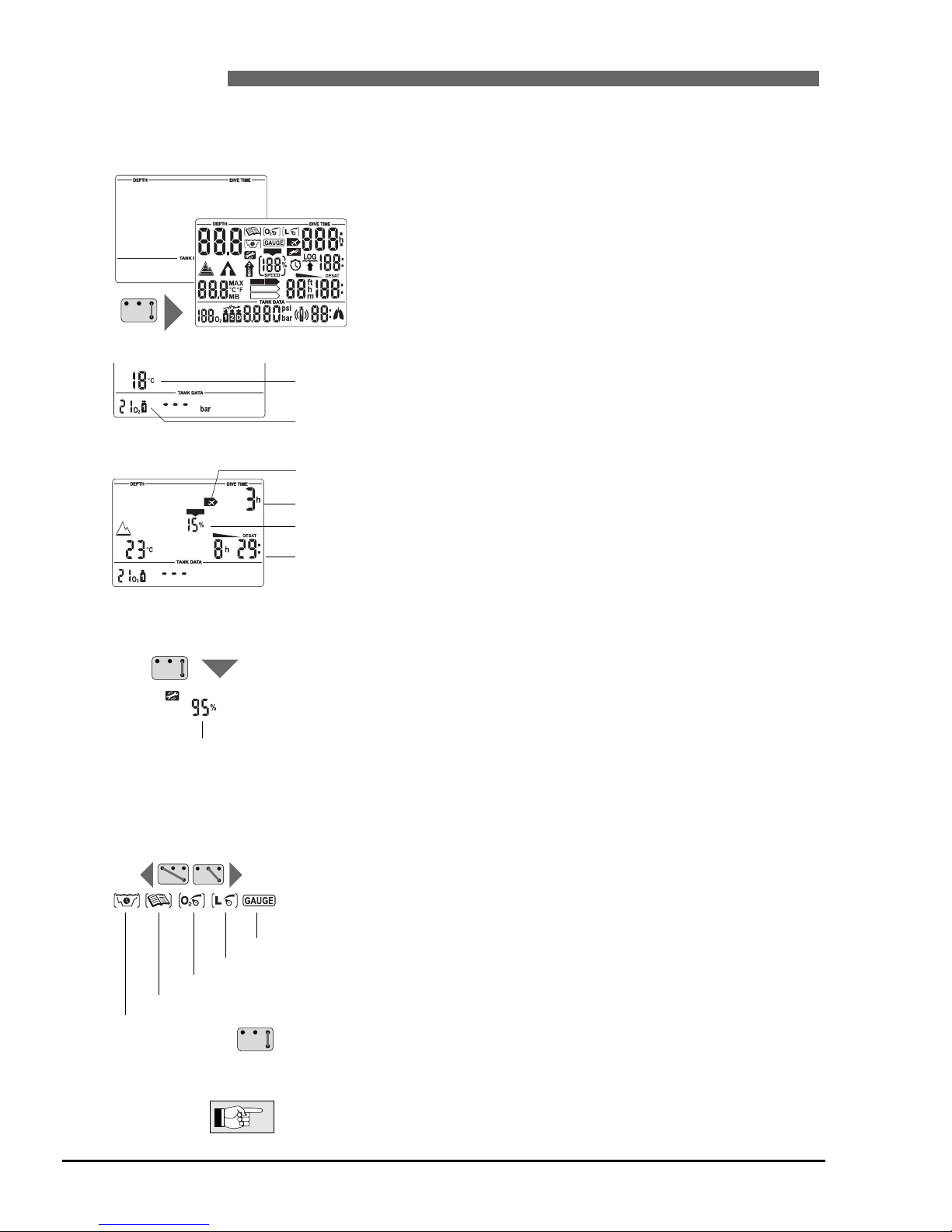
2.3 Switching on the display
• automatically, on submerging in water or when adaptation to atmospheric
pressure is necessary;
• manually, by bridging contacts on housing (B-E).
• When TEC is in state of rest no information is displayed but
the atmospheric pressure is continuously monitored. If a
higher
altitude range is detected, TEC switches on for 3 minu-
tes automatically. -> 25
• TEC switches on by bridging the contacts B and E. All
segments light up for 5 seconds.
Afterwards the display shows the selected O
2
mix, the
temperature and in certain circumstances an altitude range
->25.
If the appertaining transmitter is switched on and located
within transmitting distance, the tank pressure is displayed,
otherwise <---> will be displayed. If no transmitter has been
paired yet, the display will be blank.
If there is a remaining saturation due to the last dive or
change of altitude, TEC also displays the remaining desaturation time, the oxygen toxicity and the "no-fly time"
->24.
2.4 Checking the battery capacity
After switching on TEC you can check the battery capacity by bridging the
contacts
B and E. The remaining capacity is displayed for 3 seconds as a per-
centage. If the value reaches 0%, the battery warning gets activated (->17)
and
the battery has to be replaced by an authorised SCUBAPRO UWATEC dealer.
For a 7-day diving vacation TEC uses between 2 – 5 % of its battery capacity.
%NO%
CNS O2%
NO
NO
%
DECO
STOP
NO STOP
LEVELSTOP
CNS O2%
Do not fly icon
Battery capacity
2.5 Selection and activation of user functions
At the surface you can select the dive planner, the logbook
and gauge mode as well as the functions to enter the
O2%
mix and the microbubble levels by bridging the contacts +
and B or – and B.
After the selection of the desired function you can activate and deactivate it by
bridging the contacts B and E.
Details to the user functions are to be found on the pages mentioned above.
Gauge mode ->26
Input microbubble level ->30
Input O2mix ->18
Logbook ->39
Dive planner ->37
Temperature
O2Mix
No-fly time
Oxygen toxicity
Desaturation time
Page 11
English
11
II UWATEC®Smart dive computers
I
2 Operation / 3 SOS mode
3 SOS mode
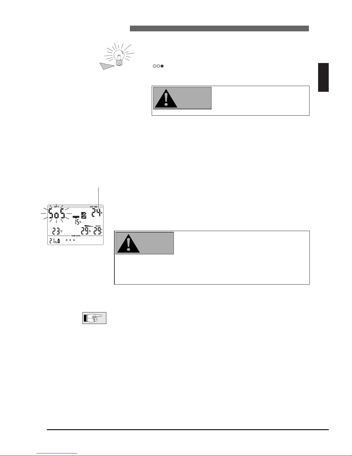
Activation: automatic
If the diver remains above a depth of 0.8m (3 feet) for more than three minutes without observing a prescribed decompression, the computer will automatically switch into SOS mode after the dive.
The display shows the "SOS" sign and the remaining length of the SOS mode.
The dive will be entered in the logbook with "SOS". Other than that the SOS
mode has no further impact on the displays and functions on the surface.
• Serious injury or death may result if a diver does
not seek immediate treatment should any signs
or symptoms of decompression sickness occur
after a dive.
• Do not dive to treat symptoms of decompression sickness!
• Diving in SOS mode is extremely dangerous and you must assume full
responsibility for such behaviour. UWATEC will assume no liability.
Once in the SOS mode, the computer will lock up and will be inoperable as a
diving instrument for 24 hours.
A diving accident can be analyzed at any time in the logbook and downloaded
to a PC by means of the infrared interface (IrDA) and the SmartTRAK software.
NO
NO
CNS O2%
%
Time remaining until
SOS mode switches
off automatically
2.6 Active backlight
The display of TEC can be illuminated both on the surface and
underwater.
The backlight can be activated by pushing and holding button
for 1 second. The light will turn off automatically after 8
seconds or after the time selected via SmartTRAK.
The backlight can only be activated if the computer display is on.
2.7 Switching off the display
On the surface TEC switches off automatically after 3 minutes without
operation.
The active backlight is no substitute
for a dive torch. When diving at
night or at increased depth we
recommend the use of a dive torch.
II
WARNING
WARNING
Page 12
12
II UWATEC®Smart dive computers
4 Setting up Smart TEC (transmitter and dive computer)
4.1 Mounting of transmitter
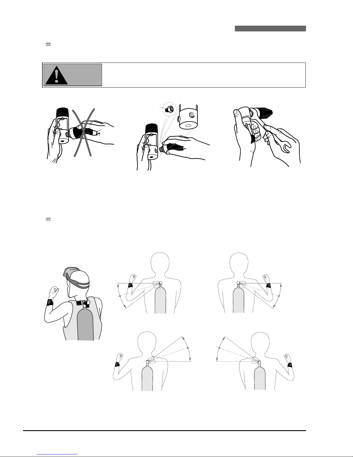
Each individual pressure tank requires a separate transmitter.
The transmitter is mounted at the high pressure (HP) outlet of the regulator’s first stage before the first
dive.
• Use air and Nitrox components in accordance with the law of the country.
Procedure:
The transmitter is best mounted laterally on the regulator.
If pressure tanks 2 and D are carried at the side, make sure the position of their transmitters in relation to TEC resembles that of the transmitter of the main tank on the back.
It is advisable to mount the transmitter on the same side that the computer is located. This is the optimal
position for transmission.
HP
Do not hold the transmitter
by its plastic part.
Mount the transmitter at the HP
oulet. If the threads do not match,
you can get a fitting adaptor at your
diving equipment retailer.
Tighten the transmitter by
means of a size 3/4" wrench.
Position of the transmitter
for left handers.
Position of the transmitter
for right handers.
Position of the transmitter for left
handers, if there is no connection
possible on the left hand side.
Position of the transmitter for right
handers, if there is no connection
possible on the right hand side.
(Adaptor)
WARNING
Page 13
English
13
II UWATEC®Smart dive computers
I
4 Setting up (transmitter and dive computer)
4.2 Pairing of transmitter and dive computer
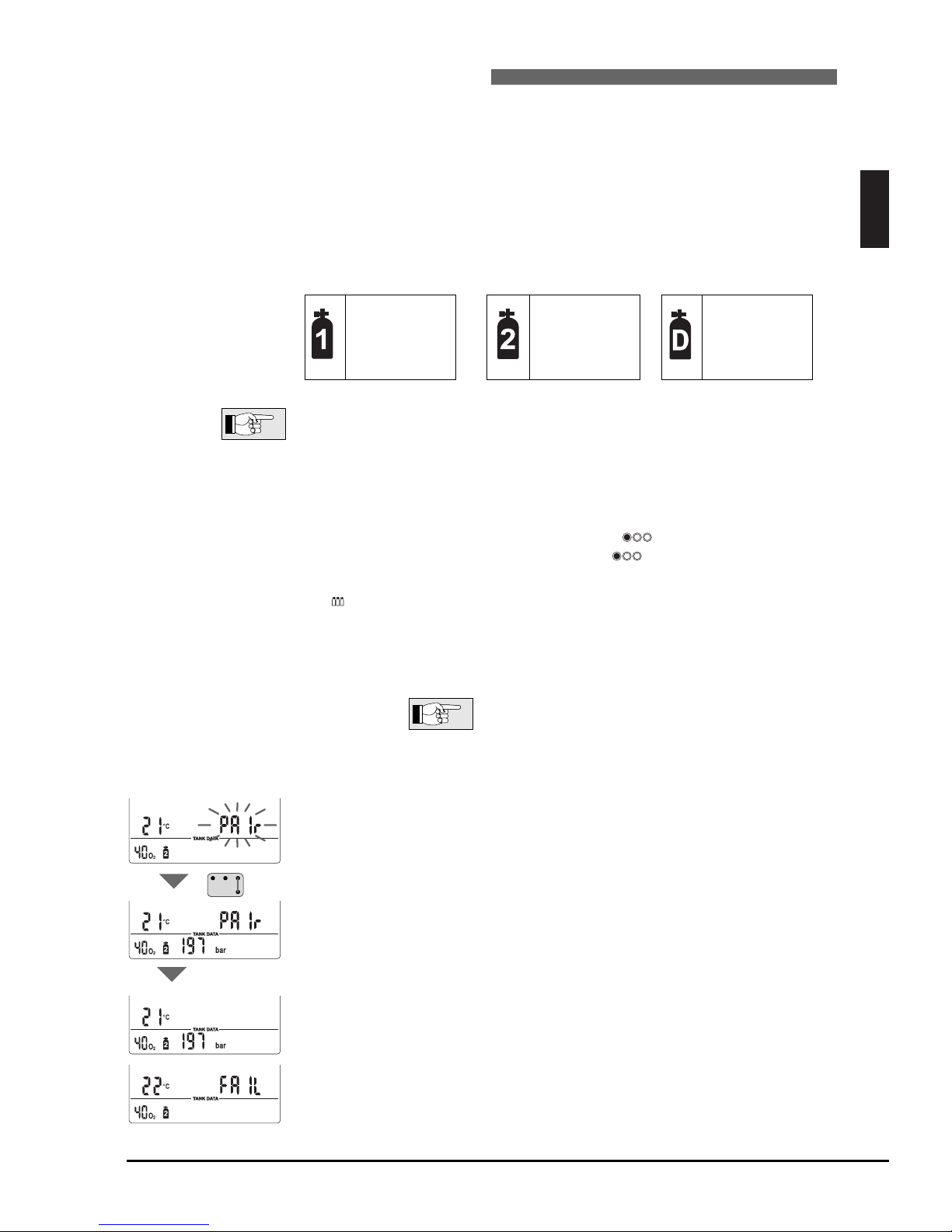
To receive the data of the transmitters, each transmitter must be assigned to one tank symbol and paired
with TEC.
Pairing is necessary:
• before the first use of TEC with the transmitter;
• if you use a new transmitter or a new computer;
• after changing the battery;
• if a different tank symbol (1, 2, or D) is to be paired to the transmitter;
e.g. The transmitter is to be paired to tank symbol D instead of tank symbol 2.
To distinguish your tanks and transmitters you should regard the following assignments:
Note that you can also set 2 or even 3 tanks to the same gas mixture. This comes
in handy when diving with twin tanks or with double outlet on a single tank.
Pairing procedure:
1. Shut the valve, depressurise the regulator and wait for 15 seconds.
2. Switch on TEC (bridge contacts B and E). Select the tank symbol you wish to
pair with a certain transmitter by pressing . Selected tank symbol will
flash. Confirm the selection by pressing for at least 1 second. Tank
symbol stops flashing.
Tank symbol 2 can only be selected after tank symbol D has been assig-
ned to a certain gas mixture.
3. Move the dive computer and transmitter into the
shown position.
Transmitter and dive computer must be in physical
contact during the entire pairing procedure.
4. Open the tank valve. The transmitter briefly sends a pairing sequence to the
computer.
5. The dive computer shows a flashing <PAIr> shortly after the valve has been
opened.
6. In order to confirm the pairing, the B and E contacts have to be bridged within 5 sec. A beep confirms the input and the <PAIr> display remains still.
7. "PAIr" disappears after approx. 10 sec.
In case of faulty pairing, the display <FAIL> appears instead of <PAIr>. In that
case, completely purge the regulator and repeat the pairing procedure. This is
only possible after at least 15 seconds.
10 sec.
%
%
Travel Mix
Transmitter 2
Intermediate
oxygen %
Deco Mix
Transmitter 3
Highest
oxygen %
%
Bottom Mix
Transmitter 1
Lowest
oxygen %
%
II
Page 14
14
II UWATEC®Smart dive computer
4 Setting up Smart TEC
• Pairing of transmitter and dive computer may already be carried out at home
and need only be executed once, before the first use.
• A transmitter can only be paired with a single tank symbol at a time. If
you try to pair the same transmitter with a second tank symbol, the first
pairing will automatically be deleted.
• The pairing of transmitter and tank symbol will remain valid, even if the
gas mixture is switched off (-> 34, switching off of gas mixtures).
• You may delete the pairing of transmitter and dive computer by means of
the SmartTRAK software.
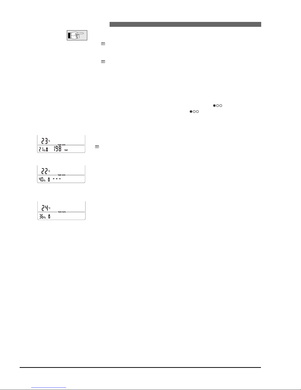
How to check if transmitter and computer are paired correctly:
1. Switch on the computer manually (B and E)
2. To check the pairing of a certain tank symbol, press to select the tank
symbol. Confirm your choice by pressing for 1 second.
3. Move the computer into transmitting range of the transmitter.
4. Open the tank valve. The transmitter switches on automatically.
5. Check the display: Pairing has been carried out correctly if the pressure is
displayed within 5-10 seconds.
Check the assignment of all tanks and transmitters as well as the pairing of
transmitters and dive computer!
If the transmitter of a selected pressure tank has been correctly paired, but TEC
cannot receive the tank pressure, "- - -" will appear on the display. In that case,
check the position of transmitter and dive computer.
If the specific channel of transmission (i.e. tank) has not been paired, or if an
existing pairing has been deleted via SmartTRAK, the display will remain empty.
In that case, transmitter and computer must be paired again.
Pairing ok
Pairing not present
%
%
Pairing present, no pressure
data available
%
Page 15
English
15
III Diving with Smart TEC
III UWATEC®Smart dive computers
III
1 Terminology / Symbols
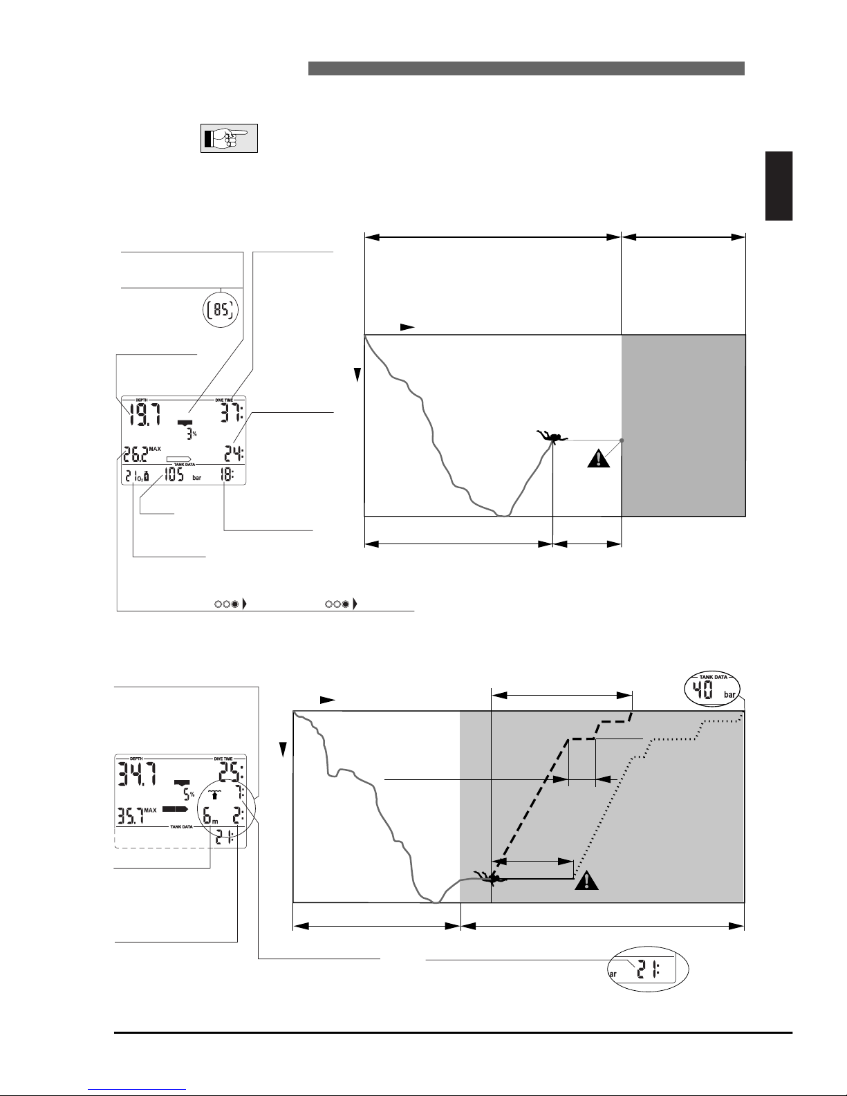
The information on the display of TEC varies depending on the kind of dive and the dive phase.
For information about diving with microbubble levels (MB levels) see chapter V
->28. Specific features of "Diving with more than one gas mixture", are described in chapter VI -> 32.
1.1 General terminology / Display during no-stop phase
37 min. Dive time
Elapsed bottom time
No-stop time
24min
Current depth
Maximum depth
26.2 m
Decompression phase
Dive phase during which
surfacing is allowed only
after decompression
stops are completed.
No-stop phase
Dive phase during which surfacing is allowed
without stop.
Time
Depth
Ascent rate
(Only while
ascending)
SPEED
%
Tank
pressure
Current depth
In metres (feet)
Maximum depth Temperature MB Level…
Maximum depth reached during the dive
No-stop time
Remaining time
at a given depth
during which ascent
is allowed without
decompression
stop (min).
Oxygen toxicity
CNS O
2%
Dive time
Duration of
the dive (min)
O
2% Mix
Selected oxygen fraction
tank 1
%
NO STOP
CNS O2%
RBT, Remaining
bottom time
%
DECO
STOP
CNS O2%
Total ascent time to surface (7 min)
6 m
35.7 m
Decompression rangeNo-stop range
3 m
Time
Depth
Decompression
stop depth
Deepest stage is
displayed.
Decompression
stop duration
Prescribed duration of the
decompression stop at the
displayed decompression
stage (minutes).
Total ascent time
Including decompression
stops in minutes.
Decompression stop
All required decompression
stops must be observed.
RBT 21 min
Deepest
decompression
stop depth
Decompressionstop duration 2 min
Remaining bottom time, RBT
Maximum remaining time at current
depth including all decompression
obligations (minutes).
1.2 Display during decompression phase / Remaining Bottom Time (RBT)
Page 16
1.3 Nitrox information (O2information)
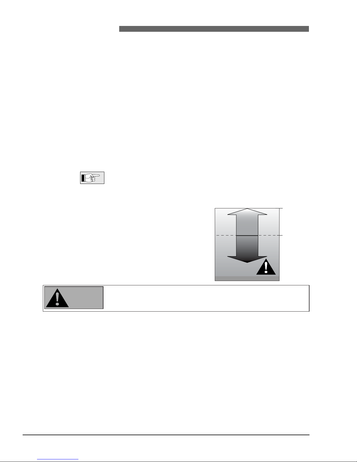
For dives with compressed air in normal recreational diving, nitrogen is the decisive gas for the decompression calculations. When diving with Nitrox, the risk of oxygen toxicity rises with the increase of the fraction of oxygen and the increase of depth and can limit dive time and the maximum depth. TEC includes
this in the calculations and displays the necessary information:
<O
2
% MIX> Fraction of oxygen: The fraction of oxygen in the Nitrox mixture can be set bet-
ween 21% (normal compressed air) and 100% in 1% increments. Your
selected mix will be the basis for all calculations.
ppO
2 max.
Maximum allowed partial pressure of oxygen: the higher the fraction of oxygen
in the mixture, the shallower the dive depth at which this value of the
partial pressure of oxygen is reached. The depth at which ppO
2
max. is reached
is called Maximum Operating Depth (MOD). Default setting is 1.4 bar, but it can
be set by means of SmartTRAK between 1.0 and 1.95 bar. When you enter the
settings for the gas mixture, TEC will display the ppO
2
max. limit setting and the
corresponding MOD. TEC warns the diver audibly and visually once the depth
is reached at which the ppO2reaches the maximum allowed value.
•
The partial pressure limit set by means of SmartTRAK can be reduced manually
at TEC (->18, setting the gas mixture).
• The CNS O2% value/alarm is not influenced by the selected ppO2max. setting.
<CNS O
2
> Oxygen toxicity: With the increased
percentage of oxygen, the oxygen in
the tissues (especially in the central
nervous system (CNS)) becomes important. If the partial pressure of oxygen rises above 0.5 bar, the CNS O
2
value increases, if the partial pressure of oxygen is below 0.5 bar, the
CNS O2value decreases. The closer
the CNS O
2
value is to 100%, the
closer the limit where symptoms can
occur. See page 21.
Nitrox diving may only be attempted by experienced divers after proper training
from an internationally recognized agency.
16
1 Terminology / Symbols
III UWATEC®Smart dive computers
CNS O2%
increases
ppO
2
0,5 bar
CNS O2%
decreases
0,21 bar
WARNING
Page 17
17
2 Attention messages and alarms
III UWATEC®Smart dive computers
TEC draws the diver’s attention to certain situations and warns the diver of unsafe diving practices. Attention messages and alarms are always visual and audible under water, only visual at the surface except the
decompression alarm.
The audible attention messages (but not the alarms) can be selectively
switched off with SmartTRAK.
III
English
2.1 Attention messages
Attention messages are communicated to the
diver visually by symbols, letters or flashing figures. In addition, two short audible sequences can
be heard (in an interval of 4 seconds) in two different frequencies under water.
Attention messages come up in the following
situations (more information can be found on the
listed pages):
Page
• Maximum Operating Depth / max ppO
2
is reached 20
• Set maximum depth is reached 19
• Oxygen toxicity reaches 75% 21
• No-stop time = 2 minutes 22
• Prohibited altitude* (surface mode) 25
•
Entering decompression when diving with L0
23
• Remaining Bottom Time < 3 minutes 22
• Tank pressure has reached set warning level 21
• Increased workload 21
• Depth for tank switch has been reached 35
Diving with microbubble levels (L1-L5):
• MB no-stop time = 0 30
• MB level stop ignored 31
• MB level reduced 31
• Entering decompression when diving
with MB level L1-L5 31
*without audible alarm
4 sec
2.2 Alarms
Serious injury or death may result from failing to
immediately respond to alarms given by TEC.
Alarms are given to the diver visually by flashing
symbols, letters or figures. In addition, an audible
sequence in one frequency can be heard during
the whole duration of the alarm.
An alarm occurs in the following situations
(more information can be found on the listed
pages):
Page
• Oxygen toxicity reaches 100% 21
• Ignored decompression 23
• Remaining Bottom Time = 0
( can be switched to attention beep) 22
• Exceeding the prescribed ascent rate 20
(Particular scale of beeps, ->20)
• Low battery alarm* see below
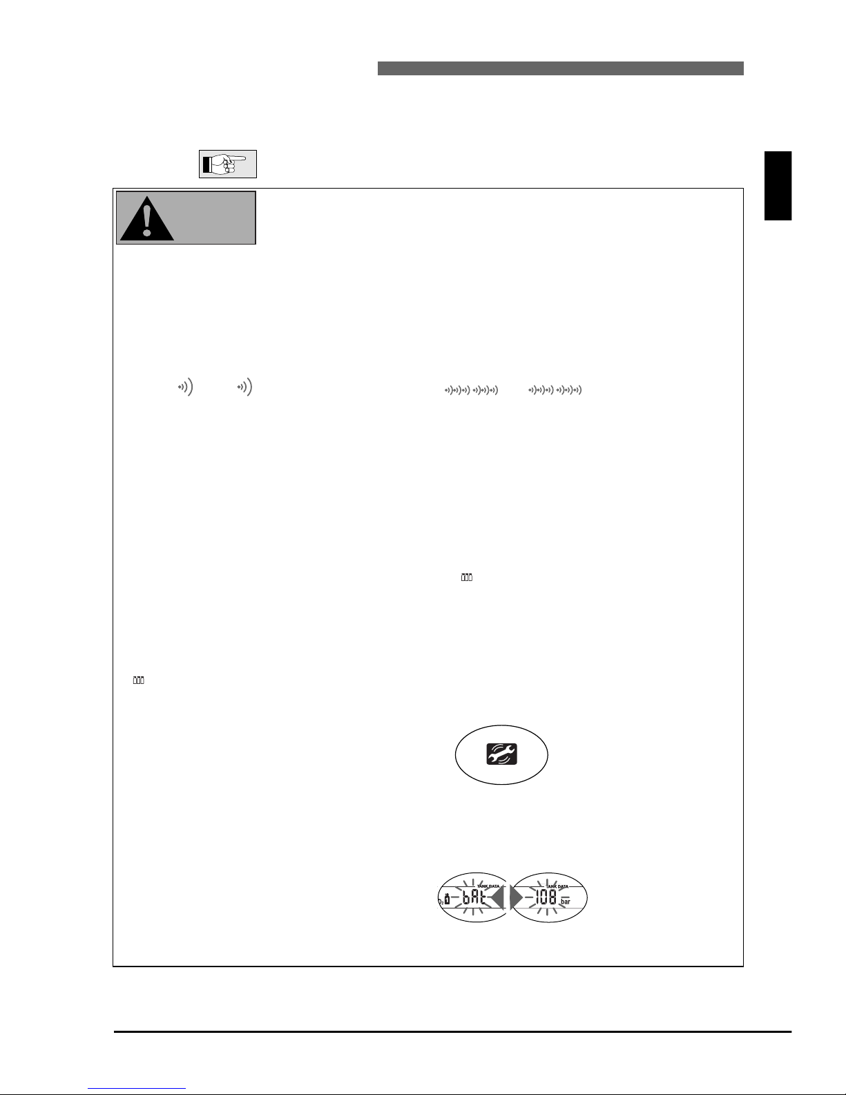
Low battery alarm TEC*
The service symbol appears if the battery capacity
reaches 0%.
Take the unit to your
authorised SCUBAPRO
UWATEC retailer.
Transmitter battery low: *
<bAt> flashing and alternating with the display of
the tank pressure.
Replace the battery in
the transmitter. ->40
*without audible alarm
(can be switched off)
(can not be switched off)
%
NO STOP
NO STOP
WARNING
Page 18
18
3 Preparation for the dive
III UWATEC®Smart dive computers
3.1 Setting the gas mixture and MOD
Before every dive and after changing the tank, make sure that the settings for the
gas mixtures correspond with the current mixtures used.
An incorrect setting causes TEC to miscalculate this particular dive. If the fraction of oxygen is set too
low this can lead to oxygen poisoning without warning. If the value is set too
high decompression sickness may occur.
Inaccuracies in the calculations are carried
over to repetitive dives.
For dives with a single gas mixture, assign the gas mixture to tank symbol 1 and shut off gas mixtures
2 and D. ->34
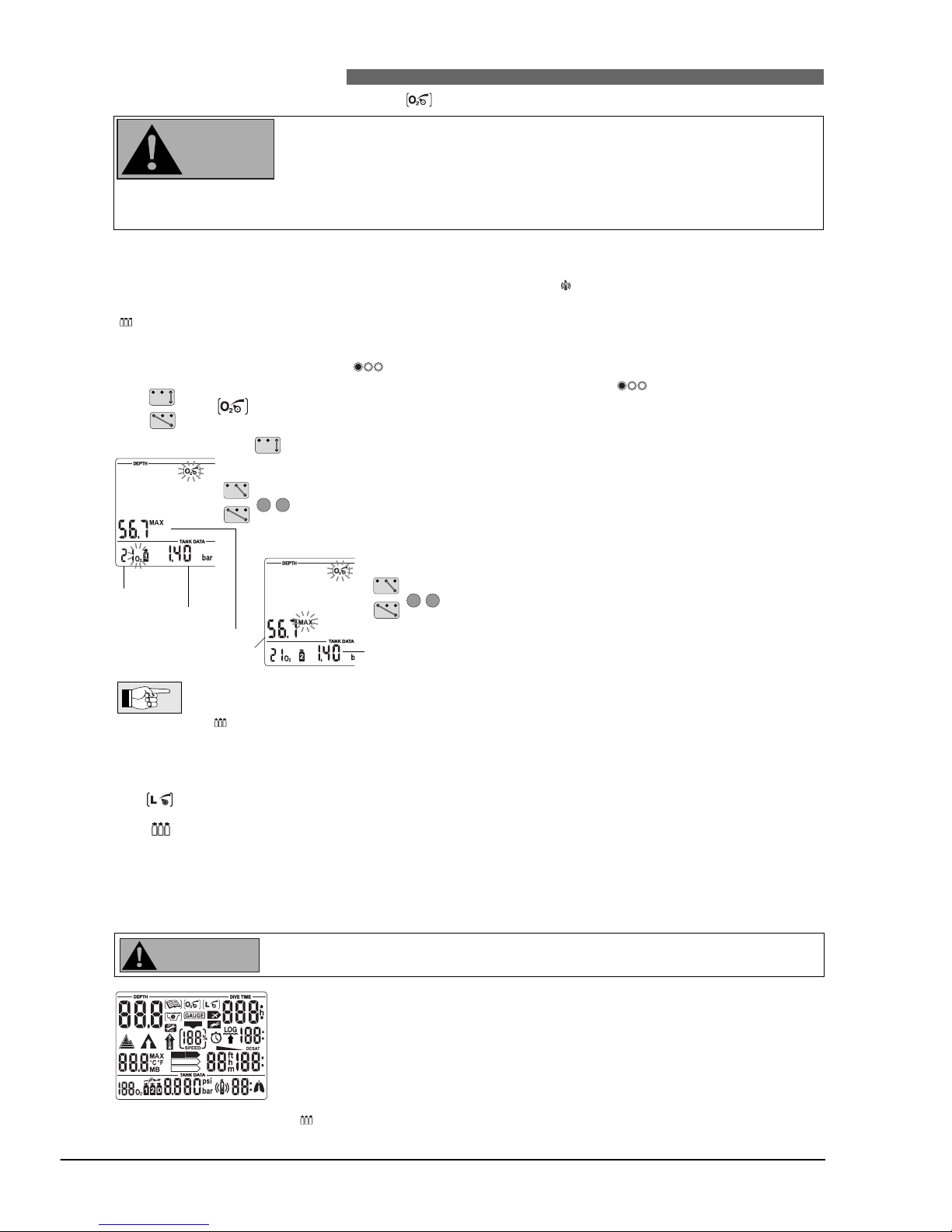
If more than one gas mixture has been selected, TEC will display at the surface and the number of
gas mixtures.
For dives with several gas mixtures please read pages 32 and 13 for further reference.
To set the gas mixture, TEC must be in user mode.
1. Press to choose the tank for the O
2
mixture you are going to enter. The
tank symbol will start flashing. Press and hold to confirm your selection.
2. Bridge contacts B and + or B and – until the symbol for the setting of the
O2mixture appears.
3. Confirm that you wish to change the displayed oxygen fraction by bridging
B and E.
4. Change the oxygen fraction in increments of 1% by bridging B and + or B
and –. TEC will display the current fraction of oxygen, the maximum parti
al
pressure limit, ppO2 max (as pre-set by means of SmartTRAK) and the MOD
.
5. Confirm the selected percentage with B and E.
6. By bridging B and + or B and – you can change the
MOD for the chosen fraction of oxygen. TEC will now
display the corresponding partial pressure limit (pp
O
2
max) for the new MOD.
7. Confirm your MOD settings with B and E.
•
Without confirmation the display will disappear after 3 minutes and your entries will not be
accepted.
•
Please refer to page 32 for the setting of gas mixtures for tanks 2 and D.
• The time to reset the O2% mix to air can be set with SmartTRAK between 1 and 48 hours
or to "no reset" (default).
3.2 Setting the MB level See chapter V, ->28
3.3 Preparation for diving with more than one gas mixture See chapter VI, ->32
3.4 Preparation for the dive and function check
The following descriptions of the preparation are based on the assumption that all transmitters have been
correctly mounted at the HP outlet of the regulators (->12) and successfully paired with TEC (->13).
1. Mount the regulator together with the transmitter on the tank
2. If present, check the reserve valve of your tank, the reserve valve must be
open.
3. Switch on TEC (B-E) and check the test display: Are all elements of the display activated? Do not use TEC if the display does not show all elements.
4. Open the valve (transmitter will switch on automatically) and check the tank
pressure (after approx. 10 seconds). If the pressure is insufficient, change the
tank.
5. Check the connections and instruments for leaks. Never dive with leaky
equipment!
Repeat 4 and 5 with all transmitters you are going to use.
…
+
–
%
…
NO
NO
%
DECO
STOP
NO STOP
LEVELSTOP
CNS O2%
O2% mix
PpO2max.
Max. Operating
Depth MOD
%
+
–
ppO2max.
WARNING
WARNING
Page 19
19
4 Functions during the dive
III UWATEC®Smart dive computers
4.1 Immersion
After immersion, starting at a depth of about 0.8 m (3 ft), TEC automatically selects gas mixture 1, all
diving functions are monitored, i.e. depth and dive time displayed, maximum depth stored, saturation of
tissues calculated, no-stop time or decompression prognosis determined, ascent rate controlled and displayed and the correctness of the decompression procedure supervised. In addition, TEC also shows the
tank pressure and about 2 minutes into the dive the Remaining Bottom Time (RBT) is displayed.
4.2 Setting bookmarks
During the dive you can create bookmarks in your dive profile by pressing . An audible signal confirms the creation of the bookmark. These bookmarks will be graphically displayed in the dive profile of
SmartTRAK.
To visualize the bookmarks on the dive profile, you must select the box “Generate bookmarks” under “Program options” in SmartTRAK.
4.3 Dive time
The whole time spent below a depth of 0.8m (3 feet) is displayed as dive time
in minutes. The time above 0.8m (3 feet) is counted as dive time only if the
diver descends again below 0.8m (3 feet) within 5 minutes.
While the dive time is running, the colons on the right of the figures are
flashing in one second intervals. Maximum dive time displayed is 999 minutes.
If a dive lasts longer than 999 minutes the dive time display starts
again at 0 minutes.
4.4 Current depth
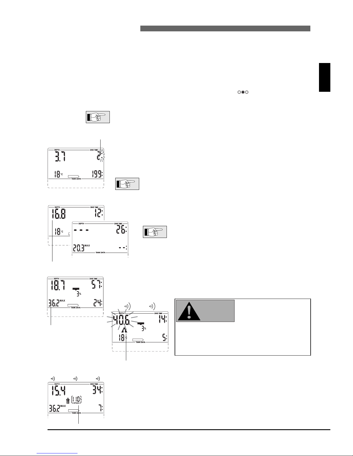
Current depth is given in 10 cm increments (1 foot). On switching
on and at a diving depth of less than 0.8 m (3 ft) the display shows
<– – –>.
Depth measurement is based on freshwater. Therefore,
TEC shows a slightly greater depth when diving in salt
water, depending on the salinity of the water. No calculation however is affected.
III
English
%
NO STOP
%
NO STOP
%
4.5 Maximum depth / Temperature
Maximum depth is only displayed if it exceeds the current depth by more than
1 m (3 feet) (maximum indicator function). If maximum depth is not displayed,
TEC shows the temperature.
Set maximum depth reached
If the maximum depth set with SmartTRAK has
been reached (default 40m/130 feet), the display
will flash and the ascent arrow will be displayed.
Ascend until the ascent arrow disappears.
4.6 Ascent rate
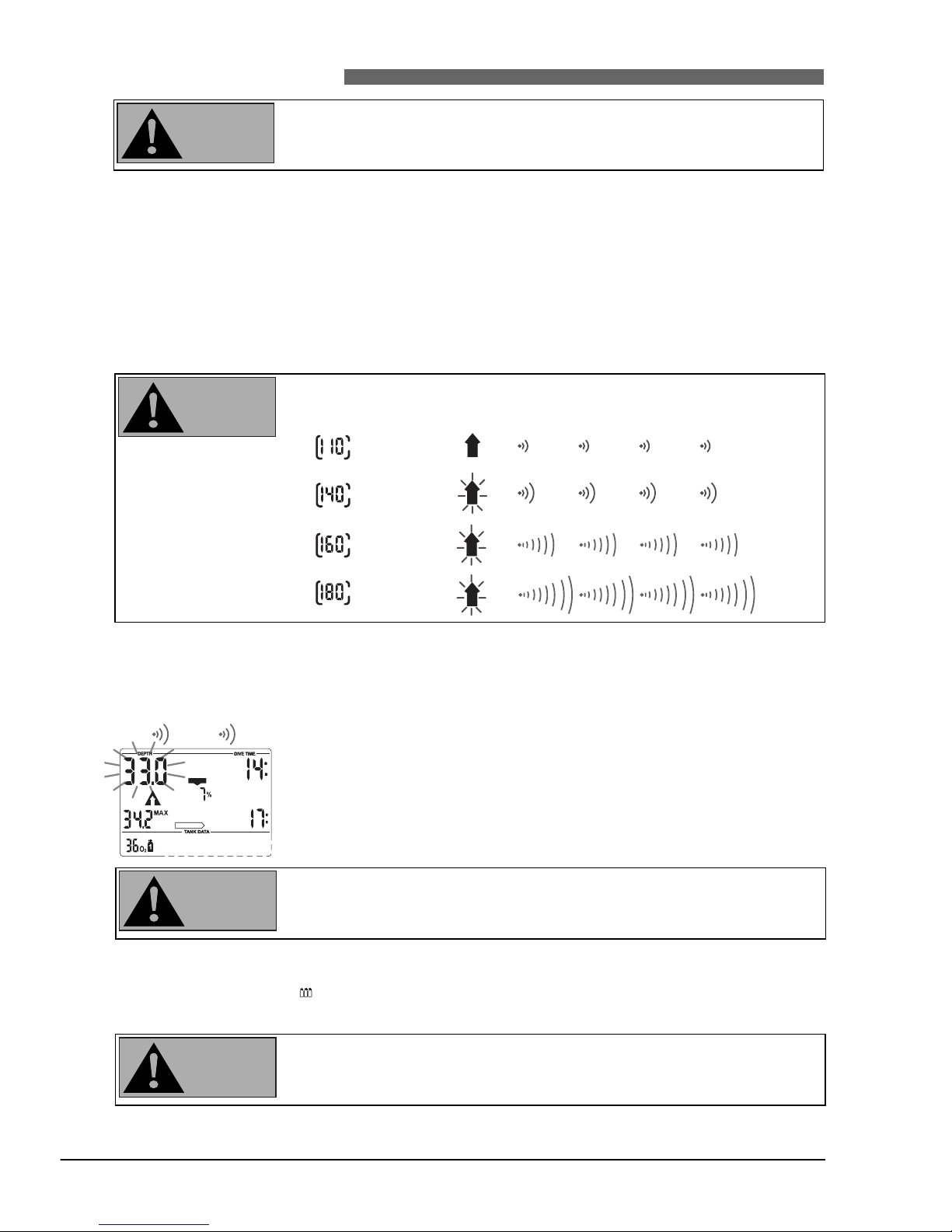
Optimal ascent rate varies depending on depth between 7 and 20 m/min (23
and 67 ft/min). It is displayed as a percent of the reference variable ascent rate.
If the ascent rate is greater than 100% of the set value, the black arrow
<SLOW> appears. If the ascent rate exceeds 140%, the arrow starts flashing.
TEC provides an audible alarm if the ascent rate is 110% or greater. The intensity of the alarm increases in direct proportion to the degree that the prescribed ascent rate is exceeded.
NO STOP
%
NO STOP
CNS O2%
%
NO STOP
CNS O2%
4 sec
Maximum depth
Ascent arrow
Current depth
Dive time
Ascent rate
WARNING
Page 20
20
4 Functions during the dive
III UWATEC®Smart dive computers
The prescribed ascent rate must be observed at all times! Exceeding the prescribed ascent rate can lead to microbubbles in the arterial circulation which
can lead to serious injury or death due to decompression sickness.
• In case of an improper ascent TEC may require a decompression stop even
within the no-stop phase because of the danger of microbubble formation.
• The decompression duration necessary for the prevention of microbubbles can
increase massively if the ascent rate is exceeded.
• From great depth a slow ascent may cause heightened saturation of tissues
and an extension of both decompression duration and total ascent time.
At shallow depth, a slow ascent may shorten the decompression duration.
• Display of the ascent rate has the priority over <CNS O
2
>.
Excessive ascent rates for longer periods are entered in the logbook.
Ascent rate Visual
alarm
Audible alarm
SPEED
SPEED
SPEED
SPEED
S
L
O
W
S
L
O
W
S
L
O
W
S
L
O
W
%
%
%
%
4.7 Partial pressure of oxygen (ppO
2 max
) / Maximum Operating Depth (MOD)
The maximum partial pressure of oxygen ppO
2 max
(default 1.4 bar) determines
the Maximum Operating Depth (MOD). Diving deeper than the MOD will expose the diver to oxygen partial pressures higher than the set maximum level.
The MOD and consequently the ppO
2 max
can be reduced manually at TEC
(->18, setting the gas mixture, point 6).
In addition the maximum allowed ppO
2
can be set by means of SmartTRAK
between 1.0 to 1.95 bar.
The MOD is a function of ppO
2 max
and the mixture used. If during the dive
the MOD is reached or exceeded TEC sends an audible attention message,
the ascent arrow appears and the current depth display starts flashing.
Ascend to a shallower depth in order to diminish the danger of oxygen poisoning.
Change to the gas mixture that is required at this depth by
selecting the appropriate tank symbol.
• The MOD should not be exceeded. Disregarding the warning can lead to
oxygen poisoning.
• ppO
2 max
should not be set higher than 1.6 bar.
%
NO STOP
CNS O2%
4 sec
WARNING
WARNING
WARNING
WARNING
Page 21
English
21
4 Functions during the dive
III UWATEC®Smart dive computers
III
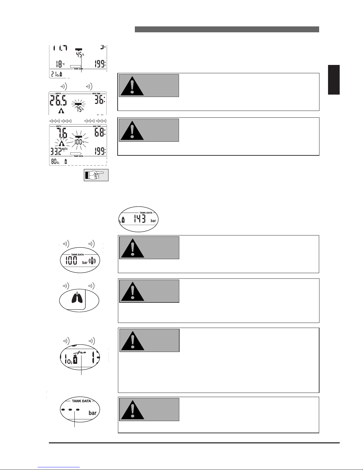
4.8 Oxygen toxicity (CNS O2%)
TEC calculates oxygen toxicity from depth values, time and the gas mixture and
displays it in the location of the ascent rate. The toxicity is expressed in 1%
increments of a maximum tolerated value (O2clock). The symbol <CNS O2> is
displayed together with the percentage.
An audible attention signal goes off if oxygen toxicity reaches 75%. The symbol <CNS O
2
> flashes
and the ascent arrow appears.
Ascend to shallower depth to decrease oxygen
loading.
When oxygen toxicity reaches 100%, an audible
alarm goes off every 4 seconds. <CNS O
2
>, the
precentage value and the ascent arrow flash. Danger of oxygen toxicity!
Start ascent at once.
• During an ascent and if the CNS O
2
% value does not increase anymore (due
to a lower partial pressure of oxygen), the audible warning is suppressed.
• During the ascent, the display of the oxygen toxicity is replaced by the ascent
rate. If the ascent is stopped, the display changes back to the indication of the
CNS value.
• TEC will display CNS O
2
% values exceeding 199 % with 199 %.
4.9 Tank pressure The tank pressure is also used for the calculation of
the remaining bottom time (RBT) and the workload.
When the tank pressure reaches the set warning
pressure (SmartTRAK) an audible alarm goes off
and the tank symbol is shown. Default value of
warning pressure: 100 bar (1450 psi)
Do not dive any deeper. Start to ascend soon.
In case of increased workload, TEC displays a lung
symbol and an audible alarm goes off. (The sensitivity of workload can be changed with SmartTRAK).
In order to prevent additional saturation, reduce
exertion, relax and breathe more slowly.
If TEC receives no data for 30 seconds, an audible
alarm goes off and the transmitter warning
appears.
If TEC does not receive pressure data for another 40 seconds, it will activate another audible alarm. RBT and transmitter warning will no longer be displayed. Instead of the tank pressure value TEC will display "- - -".
Check the position of transmitter and TEC. Start ascending at once.
TEC will switch back to its normal display as soon as new data is received.
If the tank pressure is lower than 14bar/200psi the
transmitter switches off and TEC will display "---".
Do not let the tank pressure drop below
14bar/200psi.
NO STOP
CNS O2%
%
CNS O2%
4 sec
NO STOP
CNS O2%
%
%
4 sec
4 sec
%
4 sec
Transmitter warning
If tank pressure
<14 bar/200psi
WARNING
WARNING
WARNING
WARNING
WARNING
WARNING
Oxygen toxicity
Page 22
4.11 Decompression information
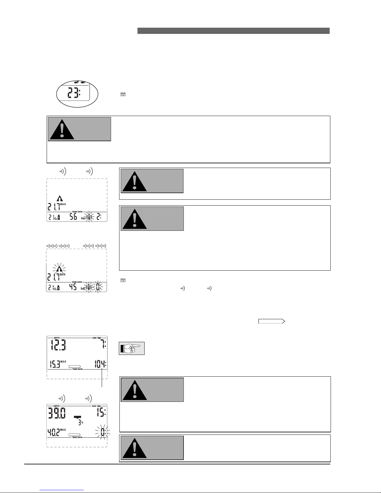
No-stop time is displayed if no decompression stops are necessary. The arrow is visible if no
decompression stops are necessary. The figures indicate no-stop time in minutes.
• No-stop display <199:> means remaining time of 199 minutes or
more.
• No-stop time is calculated on line and influenced by the current
workload and current water temperature
If no-stop time drops below 3 minutes, an audible
attention signal is activated and the no-stop value
begins to flash.
If no-stop time is less than 1 minute, the no-stop
display shows the flashing value "0".
In order to prevent a decompression dive, ascend
slowly until the no-stop time is 5 minutes or more.
Dives that require decompression stops are not
recommended.
NO STOP
22
4 Functions during the dive
III UWATEC®Smart dive computers
%
NO STOP
%
NO STOP
CNS O2%
4 sec
No-stop time
4.10 Remaining Bottom Time (RBT)
RBT is the time left at the current depth until the point of time when the ascent
must be started. The RBT is calculated on the basis of the current tank pressure,
breathing rate, the temperature, and the dive data so far recorded. The RBT is
based on the assumption that the tank pressure should amount to the set pressure (default 40 bar/600 psi) at the end of the dive. Alterations can be made with
SmartTRAK. A graphic representation of RBT is on page
15.
During dives with several gas mixtures, the calculation of the RBT is based
on the assumption that the diver will use the current gas mixture to finish the
dive.->34, 35
Never allow the RBT to go below three minutes. If the RBT goes below three
minutes there is a danger of insufficient supply of gas mixture for the ascent
as well as an increased risk of decompression sickness, and serious injury or
death may result!
Correct calculation of RBT when using a reserve or “J“ type valve is possible only if the reserve function of the valve is in the open (down) position during the dive.
If the RBT drops below three minutes, an audible
attention signal is activated, the ascent arrow is displayed and the tank icon start flashing.
Start ascent immediately.
The RBT value should never reach <0:>. With
RBT=0 the remaining tank reserve may not be sufficient for the ascent.
When the last minute has passed (RBT=0) an audible alarm is activated every
4 seconds. The RBT, the ascent arrow and
the tank icon
start flashing.
The
audible alarm
*
on exceeding the RBT is suppressed at depths less than 6.5
m (21 ft) if TEC is in the no-stop phase.
Start ascent at once.
* The audible RBT alarm can be changed to an audible attention signal by
means of SmartTRAK.
%
NO STOP
%
NO STOP
4 sec
4 sec
RBT < 3 minutes
RBT = 0 minutes
WARNING
WARNING
WARNING
WARNING
WARNING
Page 23
English
23
4 Functions during the dive
III UWATEC®Smart dive computers
III
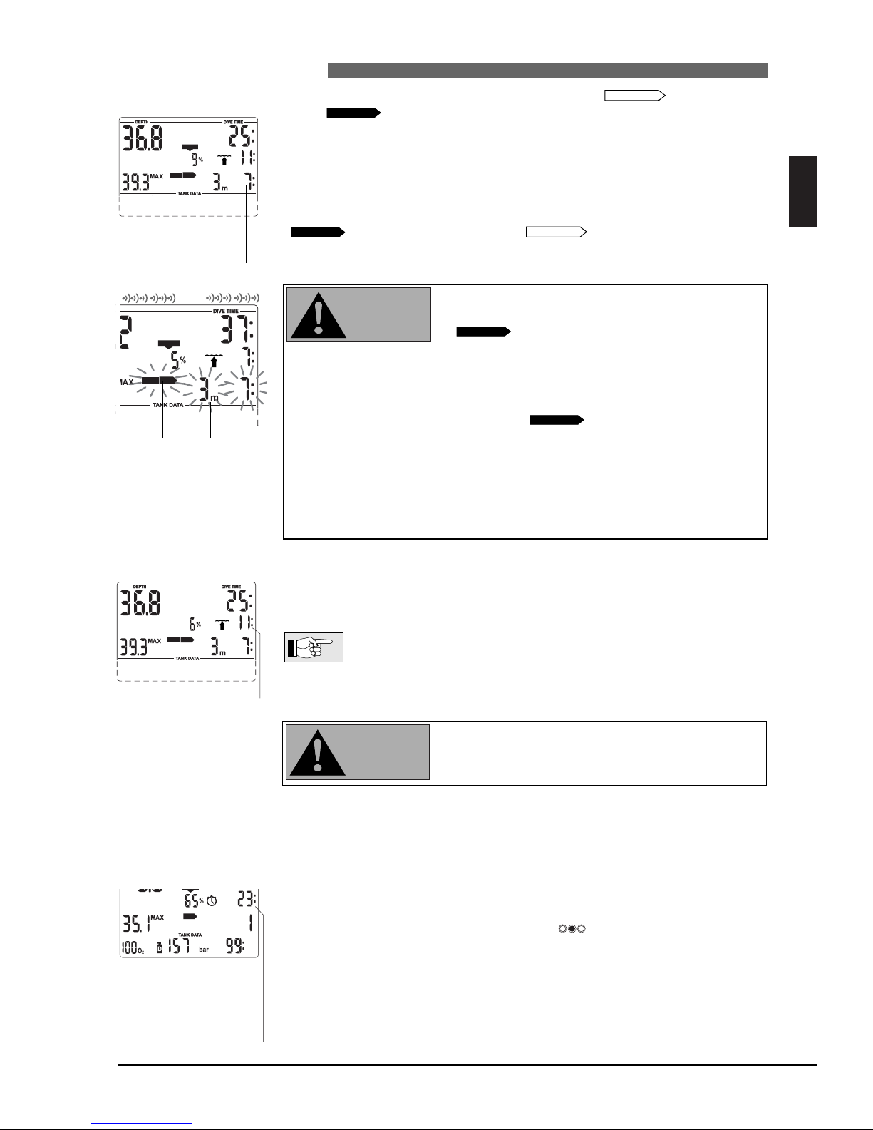
Decompression values On entering the decompression phase, the arrow disappears, the
arrow appears and an attention beep goes off. Right beside the
arrow, the deepest decompression stage in metres (feet) is displayed. Next to
the decompression stop depth, the decompression stop duration of the displayed stage appears in minutes. The display <3m 7:> means that a decompression stop of 7 minutes at a depth of 3m has to be made.
When a decompression stop has been finished, the next higher decompression
stop is displayed. When all decompression stops have been made, the arrow
extinguishes and the arrow reappears. The indication of
time on the lower right shows the no-stop time again.
Deco stop depths deeper than 27m (90 ft) are displayed as <– – : – – >
The decompression alarm is activated if the
decompression stop is ignored. The arrow
, the decompression stop duration and
decompression stop depth begin to flash and an
audible alarm goes off.
Due to the formation of microbubbles, decompression can increase massively if a decompression stop is ignored. When the surface is reached during
the decompression alarm, the arrow
, the decompression stop
duration and decompression stop depth
continue flashing, in order to
point to the risk of a decompression accident. The SOS mode is activated 3
minutes after the dive if corrective action is not taken (->11).
If the total (cumulative) duration of the decompression alarm is longer than
one minute, it is entered in the logbook.
Descend to the prescribed decompression stop depth immediately!
Total time of ascent
As soon as decompression stops are necessary TEC shows the total time of ascent.
This includes the ascent time from the current depth to the surface and all decompression stop obligations.
The total time of ascent is calculated on the basis of the prescribed
ascent rate and a normal workload. Total time of ascent can be
subject to change if the ascent rate is not ideal (100%) or if TEC
detects a higher workloa
d.
Ascent time greater than 199 minutes is displayed as <– –>.
On all dives with TEC, make a safety stop for at least
three minutes at a depth of 5 m (15 feet).
DECOSTOP
DECOSTOP
NO STOP
DECOSTOP
DECOSTOP
NO STOP
DECO
STOP
CNS O2%
%
DECO
STOP
Total time of ascent
%
DECO
STOP
CNS O2%
Decompression
time
Decompression
stop depth
4.12 Safety stop timer
The safety stop timer displays the time span a diver should spend at the safety stop depth at the end of
the dive. The timer is activated by the diver and counts back to zero, starting with the time that was
pre-set with SmartTRAK. It can be restarted any number of times. Range: 1 - 5 minutes (default 3 min.)
The safety stop timer can be activated under the following conditions:
Depth
< 6.5 m
(21 ft)
, no-stop display 199 min., gauge mode is switched off.
Activate the safety stop timer by pressing . The timer begins to count
backwards and a bookmark will be created in the dive profile.
The safety stop timer will switch off automatically if the depth exceeds 6.5 m
(21 ft) or the no-stop phase is shorter than 199 minutes.
%
STOP
CNS O2%
safety stop
icon
remaining time span
minutes
seconds
Ignored decompression
alarm
WARNING
WARNING
Page 24
24
5 Functions at the surface
III UWATEC®Smart dive computers
5.1 End of a dive
After reaching the surface (<0.8 m/3 ft) TEC remains in dive mode for 5 minutes.
The delay allows for surfacing for a short period for orientation.
After 5 minutes the dive is closed and it is entered into the logbook.
For the calculations of the desaturation and no-fly time it is assumed that the
diver breathes air while on the surface.
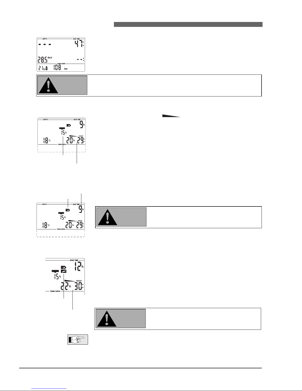
5.2 Desaturation time
After the dive has been closed
,
desaturation time in hours and
minutes and, if available, oxygen toxicity is displayed. Desaturation time is
determined either by oxygen toxicity, nitrogen saturation or the regression of
microbubbles, depending on which requires the longer time. Oxygen toxicity
(<CNS O
2
>) is displayed and adjusted until the value becomes 0%.
Desaturation time is indicated until the next dive or until it reaches zero.
The display is switched off to save energy three minutes after the last manipulation is made. The calculations are nevertheless continued in the background.
5.3 No-fly time
The <no-fly time> is indicated beside the icon <do not fly>. <No-fly time> is the
time in hours that should pass before a flight and is displayed and adjusted until
the value becomes 0 hours.
Flying while TEC displays <do not fly> may lead to
serious injury or death from decompression sickness.
DESAT
%
NO
%
CNS O2%
NO
%
CNS O2%
Desaturation time
Oxygen toxicity
Do not fly icon
No-fly time
5.4 Microbubble warning
Through repetitive dives microbubbles accumulate in the lungs if the surface
interval is not long enough. Ignoring decompression stops or ascending at an
excessive rate can also lead to microbubbles in tissues. In order to reduce the
risk of decompression sickness for repetitive dives, the surface interval should
be planned long enough. If TEC calculates that the formation of microbubbles
occurs during the surface interval, it will advise a diver to extend the surface
interval via the microbubble warning. The duration of the microbubble warning is visible by entering the dive planner -> 37.
If the <microbubble warning (NO DIVE)> is visible
during the surface interval, the diver should not
undertake another dive.
If the dive is made in spite of the microbubble warning, the diver must cope
with a clearly shorter no-stop time or an extension of decompression. Also, the
duration of the microbubble warning at the end of the dive can increase considerably.
NO
CNS O2%
NO
Microbubble
warning
Desaturation time
WARNING
WARNING
WARNING
Page 25
English
25
6 Diving in mountain lakes
III UWATEC®Smart dive computers
III
%
Altitude range 1
Desaturation time
Adaptation time
Altitude ranges
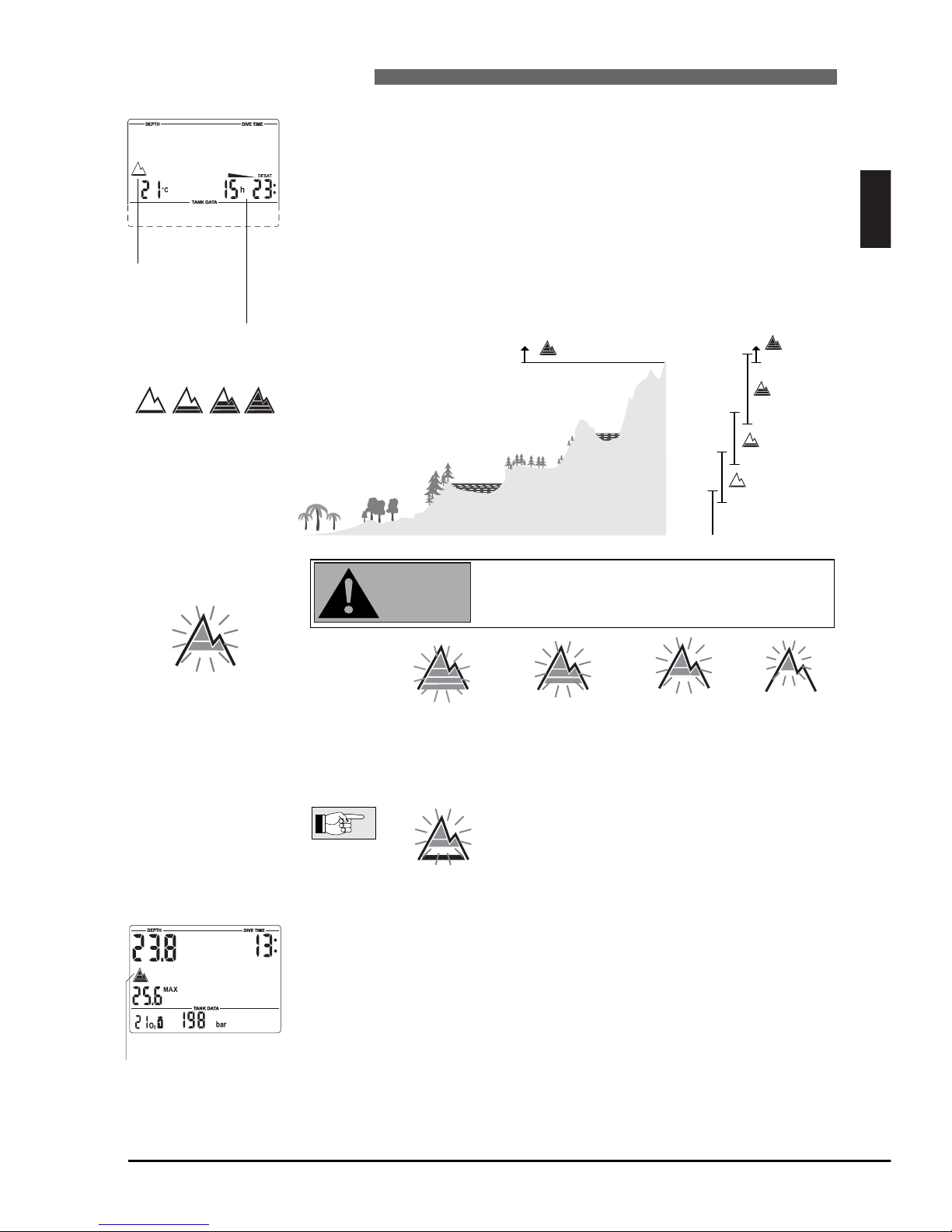
1 2 3 4
6.2 Prohibited altitude
TEC shows via flashing alti
tude segments while at
the surface to which altitude
the diver may not rise.
The ascent prohibition can also be displayed together with an
altitude range:
Example: You are at 1200 m (3937 ft) (altitude
range 1) and you may ascend to range 2 only
(2650 m / 8694 feet). You may not rise to the altitude range 3 or 4.
Ascent to altitude range 3
and 4 prohibited.
Max. allowed altitude:
2650 m (8694 ft).
6.3 Decompression dives in mountain lakes
In order to assure optimal decompression even at higher altitudes, the 3m (10
ft) decompression stage is divided into a 4 m (13 ft) stage and a 2 m (7 ft) stage
in altitude ranges 1, 2 and 3. The prescribed decompression stop depths are, in
sequence, 2m / 4m / 6m / 9m… (7 ft / 13 ft / 20 ft / 30 ft…).
If atmospheric pressure is below 620 mbar (8.99 psi) (altitude higher than
4100 m / 13450 ft above sea level), no decompression data is calculated and
displayed (automatic gauge mode). In addition RBT and the dive planner are
not available anymore. The oxygen toxicity and the tank pressure are still indicated.
%
Dive at altitude range 4:
• no deco data
• no RBT
6.1 Altitude ranges TEC measures the atmospheric pressure every 60 seconds even while the display is switched off. If the computer detects a sufficient increase in altitude, it
switches on automatically and indicates the new altitude range (1-4) and the
desaturation time. Desaturation time indicated at this moment refers to
adaptation time at this altitude. If the dive starts within this adaptation time,
TEC treats it as a repetitive dive,
since the body is offgassing.
Altitude is divided into five ranges, which are influenced by barometric pressure. That is why the defined altitude ranges overlap on their fringes. If a mountain lake is reached, the altitude range is indicated at the surface, in the logbook and in the dive planner by a stylised mountain
filled with one or more of
4 segments representing the 4 ranges. Sea level to an altitude of approximately
1000m (3300 feet) is not
indicated. In the following
diagram, you can see the
approximate breakdown of
the altitude ranges
:
4000 m
13120 ft
2000 m
6560 ft
1000 m
3280 ft
3000 m
9840 ft
0 m
905 mbar
13.12 psi
815 mbar
11.82 psi
725 mbar
10.51 psi
610 mbar
8.85 psi
Switching
at approx.
No deco data
gauge mode
WARNING
Max. altitude: 850 m 1650 m 2650 m 4000 m
2790 ft 5413 ft 8694 ft 13120 ft
Page 26
26
IV Gauge mode
IV UWATEC®Smart dive computers
In gauge mode ALL audible and visual alarms and attention messages are
turned off. This includes ascent speed, low tank pressure and interrupted
signal from transmitter.
In gauge mode TEC will display depth, dive time and tank pressure, the maximum depth is stored, ascent
rate and tank pressure are monitored. By pressing you can switch from maximum depth to temperature and vice versa. You can also activate the stopwatch and check the split time. Gauge mode does not
support the calculation of no-stop time or the supervision of decompression. Supervision of ppO
2
max and
CNS O2% will also be switched off. TEC will display no information about RBT or microbubble development. Bookmarks can be set. The settings for gas mixtures, MOD and microbubble level cannot be set and
the dive planner cannot be selected.
• Dives in gauge mode are performed at your own risk!
• After diving in gauge mode you should wait for at least 48 hours before
using a decompression computer.
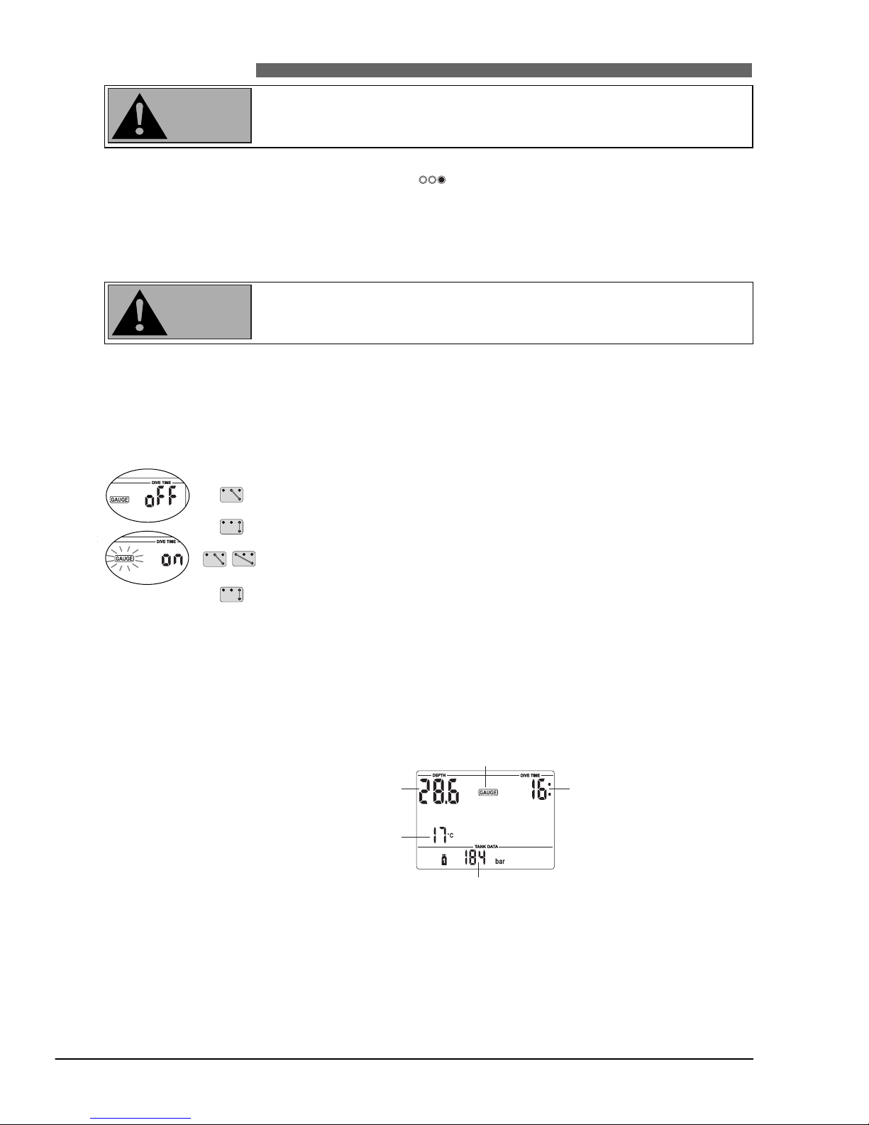
Switching the gauge mode on and off
Gauge mode can be switched on and off at the surface, if no desaturation time
is being prescribed.
After diving in gauge mode, TEC can not be used as dive computer for 48
hours.
Procedure:
1. Bridge contacts B and + or B and – until the gauge symbol and "on" or
"off" are displayed.
2. Confirm with B and E that you wish to activate or deactivate the gauge
mode. The gauge symbol starts flashing.
3. By bridging contacts B and + or B and – the gauge mode is switched on and
off.
4. Confirm your settings with B and E.
Without confirmation the display will disappear after 3 minutes and your
entries will not be accepted.
Diving in gauge mode
After immersion, starting at a depth of about 0.8m (3 ft), TEC automatically selects gas mixture 1.
The following information is displayed in gauge mode:
Changing the gas mixtures in gauge mode
In gauge mode it is up to the diver to decide on a time and depth to change
the gas mixture. TEC will not indicate a necessary change of gas mixture. For
more information about changing the gas mixture see page 35.
Dive timeCurrent depth
Gauge icon
Maximum depth /
Temperature
Tank pressure
WARNING
WARNING
Page 27
Stopwatch
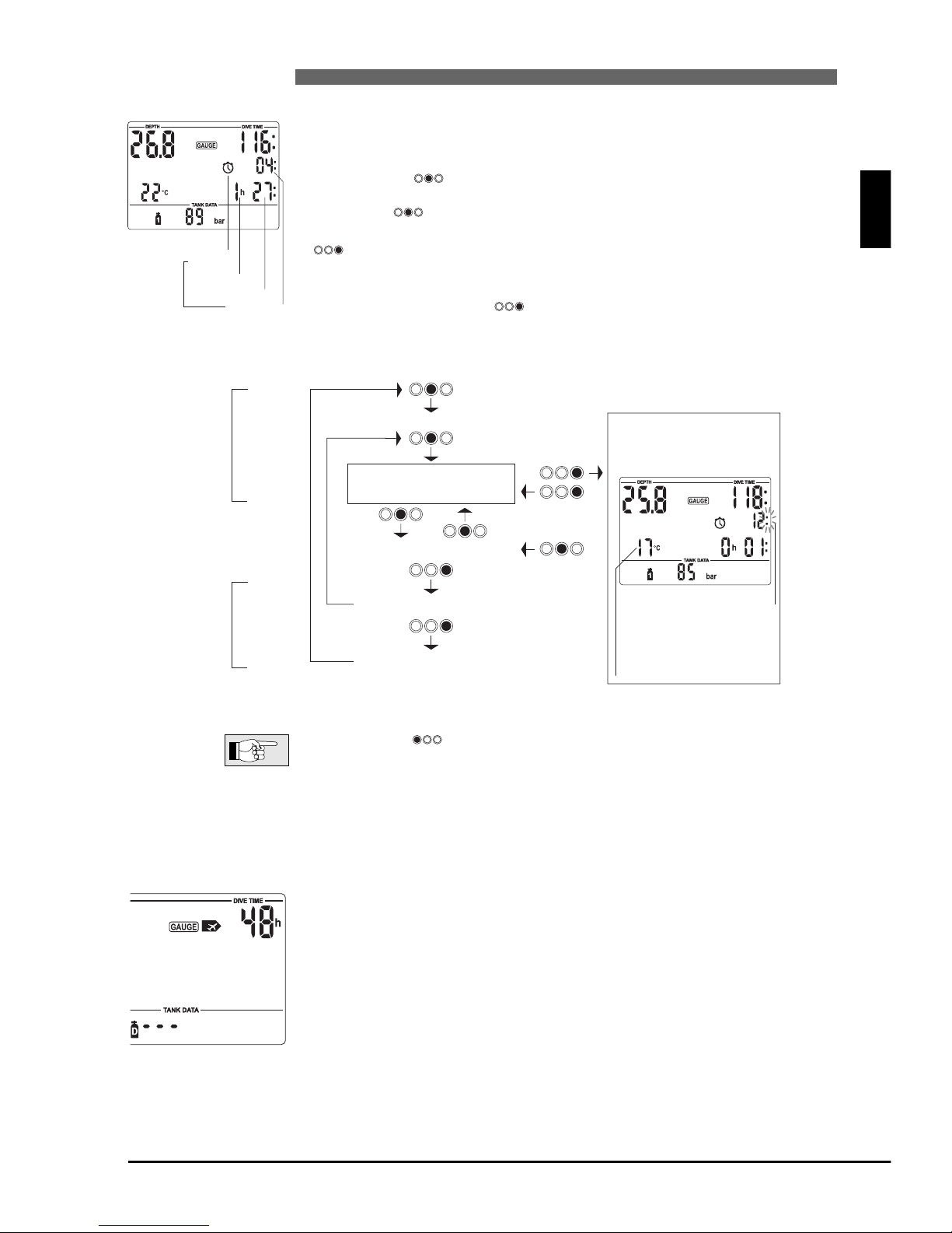
In gauge mode, after immersion, TEC will automatically monitor the dive time
and at the same time activate the stopwatch. If the gauge symbol and "on"
are displayed (-> 26, point 1) the stopwatch can also be activated at the surface by pressing . The stopwatch will run for a maximum of 1 hour at the
surface and no longer than 24 hours underwater.
By pressing you can start, stop and restart the stopwatch.
Once the stopwatch has been stopped, you can reset the timer to zero with
.
While the stopwatch is running you can measure split times and return to the
timer display by pressing . The timekeeping is not interrupted in the
meantime.
• By pressing you can select a different pressure tank even while the
stopwatch is running or the split time is being displayed.
• At a diving depth of less than 0.8m (3 ft) the stop watch will automatically
measure and display the split time. If the diver descends again the stopwatch
timer will be displayed again.
After diving in gauge mode
TEC shows the remaining time span during which it cannot be used in computer mode. Once the waiting period is over, the gauge mode can be switched
off manually. ->26
The no-fly time after diving in gauge mode is 48 hours.
Desaturation time will not be displayed.
English
27
IV Gauge mode
IV UWATEC®Smart dive computers
III
Hours
Minutes
Seconds
Stopwatch icon
Timing
NO
Stopwatch activated
00h00 00
Example
Time reset00h00 00
Stopwatch is running
Split time
(stopwatch continues to
run in the background)
00h00 15
Stopwatch halted00h02 35
Stopwatch
will start
automatically
after
immersion
Automatically
at the end of
dive
Exit stopwatch
Icon for split time
When split time is
taken, the temperature is
displayed for 5 seconds.
Page 28
28
V Diving with microbubble levels (MB)
V UWATEC®Smart dive computers
The following chapter deals with the characteristics of diving with microbubble levels (MB levels).
For general information about displays and features of diving with TEC see chapter III.
Microbubbles are tiny bubbles that can build up inside a diver's body during any dive and normally dissipate
naturally during an ascent and on the surface after a dive. Dives within no-stop time and observance of decompression stops do not prevent the formation of microbubbles in the venous blood circulation.
Dangerous microbubbles are those migrating into the arterial circulation. The reasons for the migration
from the venous blood circulation to the arterial circulation can be a great many microbubbles collecting in
the lungs. UWATEC has equipped Smart dive computers with a new technology to protect from microbubbles.
The diver chooses – according to his/her needs – an MB level and influences through it the level of pro-
tection from microbubbles.
Diving with MB levels requires additional ascent stops (level stops), the ascent is slowed down and the body gets more time to desaturate. This works contrary to the formation of the microbubbles and increases the safety
.
Smart TEC features 6 microbubble levels (L0-L5). Level L0 corresponds to UWATEC's well-known
decompression model ZH-L8 ADT and does not require level stops due to microbubble formation. Levels L1
to L5 offer additional protection from microbubble formation with level L5 offering the highest protection.
Similar to the display of information during decompression dives or dives within no-stop time, TEC displays
depth and duration of the first level stop as well as the total time of ascent as soon as the MB no-stop time
has run out. As the MB no-stop time is shorter than the ordinary no-stop time a diver will be required to carry
out a stop (level stop) sooner than a diver using level L0.
If a diver ignores a required level stop, TEC will change over to a lower MB level and the dive can not be
completed with the initially chosen MB level. E.g. If a diver sets level L4 on TEC prior to the dive and during the
dive ignores the stops recommended TEC will automatically adjust the setting to level L3 or lower.
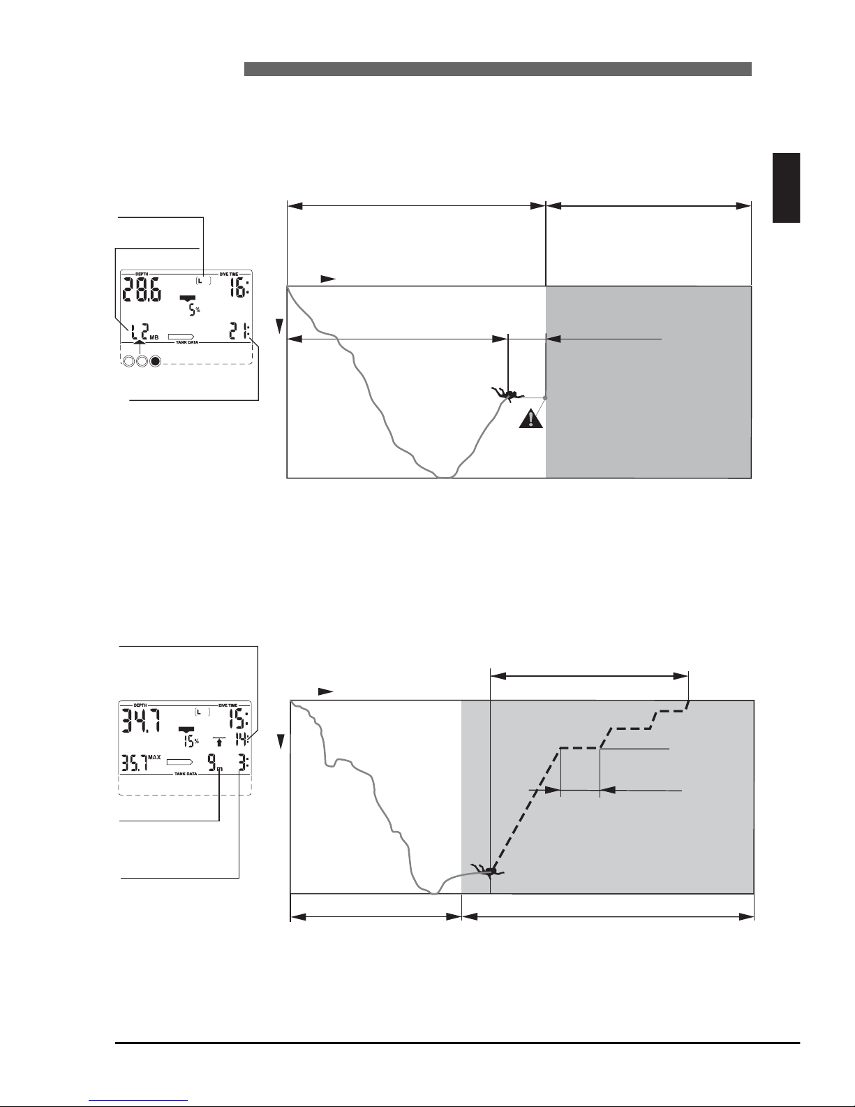
1 Comparison of dives with MB level L0 and MB level L5
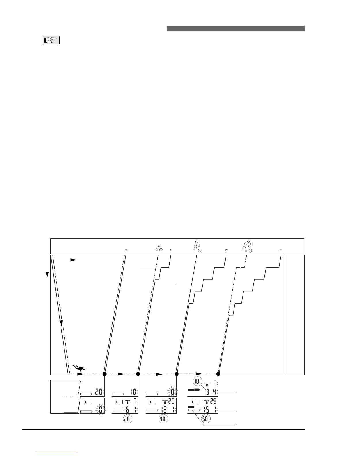
When two Smart TECs are used simultaneously, one unit is set for example to MB level L5, the other to
L0, the no-stop time will be shortened and level stops will be required before the diver has the obligation
of a decompression stop. These additional level stops help dissipate the microbubbles.
3m/10ft
6m/20ft
9m/30ft
12m/40ft
15m/50ft
Time
Depth
Microbubble
level
Microbubble accumulation
at the end of dive
Stop depth
L0
L5
L0
L5
m
DECO
STOP
m
LEVELSTOP
m
LEVELSTOP
NO STOP
m
LEVELSTOP
NO STOPNO STOP
NO STOP
DECO
ft ft
ft
ft
Decompression values
Level stop values
Decompression obligation, ->31
Page 29
English
29
2 Terminology
V UWATEC®Smart dive computers
V
This chapter will exclusively deal with terminology and display features used while diving with MB levels.
All other features are described in chapter III (page 15).
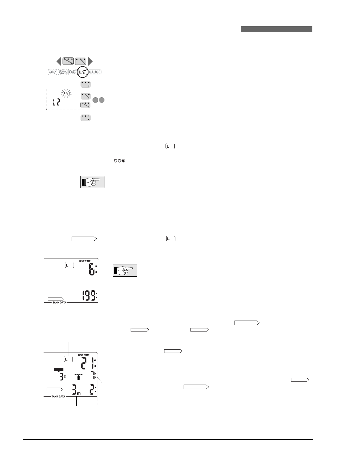
2.1 Display during microbubble (MB) no-stop phase
Dive time MB no-stop time
21min
Current depth
Maximum depth
29.9 m
Level stop phase
MB no-stop phase
Dive phase during which surfacing is
possible without MB level stop.
Time
Depth
MB level
activated
Level L2 is active
MB no-stop time
Remaining time at a
respective depth allowing
ascent without level stop.
%
NO STOP
CNS O2%
2.2 Display during level stop phase
Lowest level
stop depth
Total ascent time (14 min)
3 min
Level stop duration
MB no-stop phase
Time
Depth
Level stop duration
The duration of a level
stop at a given level
stop depth is displayed.
Level stop depth
The deepest level
stop is displayed.
Total ascent time
including level stops
Level stop phase
To complete the dive without being
reduced to a lower MB level all
requested level stops must be
observed.
%
LEVELSTOP
CNS O2%
35.7m
9m/30ft
6m/20ft
3m/10ft
Page 30
30
3 Preparation for a dive with microbubble levels (MB levels)
V UWATEC®Smart dive computers
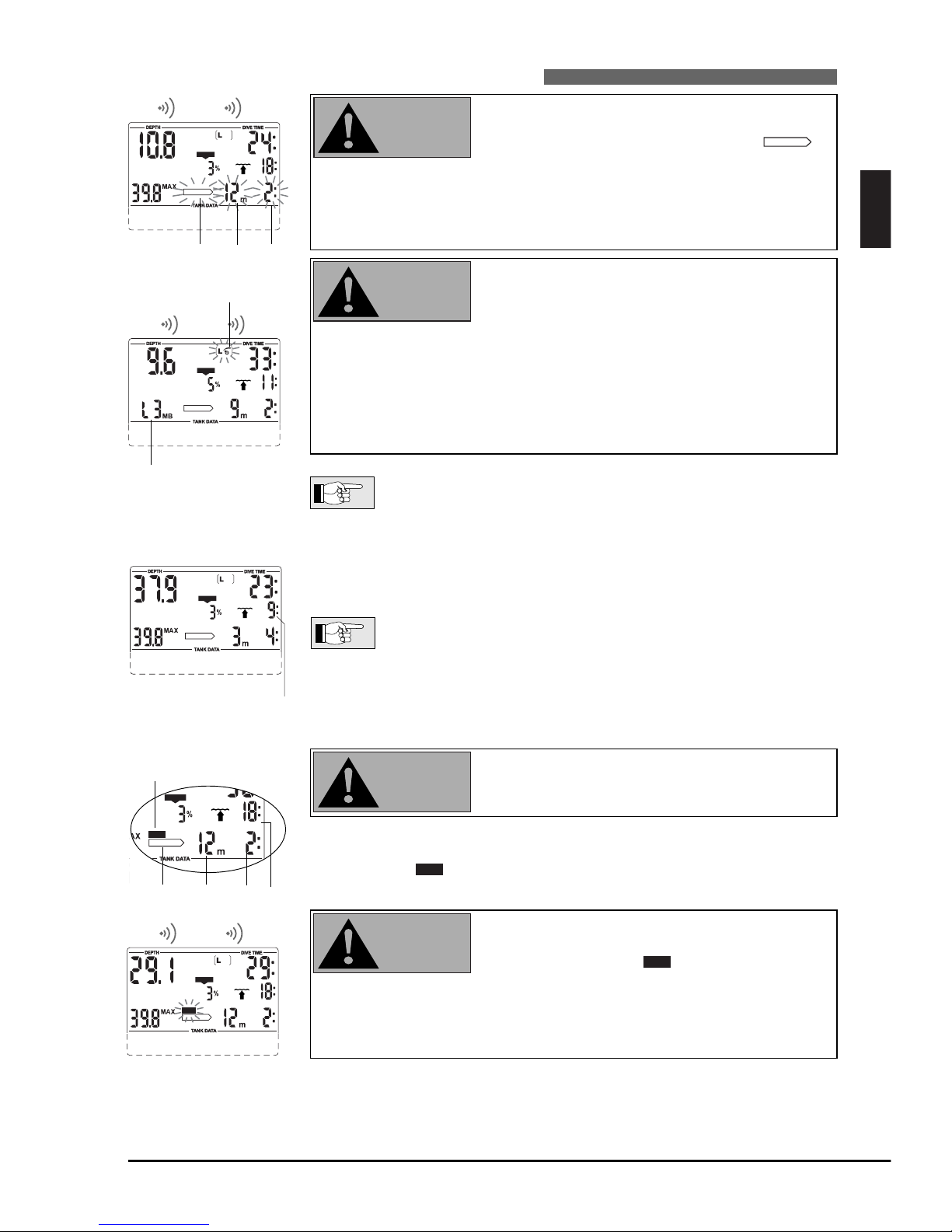
3.1 Setting the MB level
To change the MB level TEC must be in user mode.
1. Bridge contacts B and + or B and – until the symbol for MB levels appears.
2.
Confirm that you wish to change the displayed MB level by bridging B and E.
3. Change MB level by bridging contacts B and + or B and – .
4. Confirm with B and E the selected MB level.
Without confirmation the display will disappear after 3 minutes and your
entries will not be accepted.
TEC will display the symbol to confirm that an MB level beyond L0 (L1-L5)
has been chosen. During the dive the MB level is shown by pressing briefly
. If however a level stop is ignored, the new MB level is permanently
shown (->31).
MB levels have an influence on the dive planner.
4 Functions during the dive with microbubble levels
4.1 Level stop information
Microbubble (MB) no-stop time
While diving with MB levels L1 to L5 TEC will display the MB no-stop time instead of the ordinary no-stop
time. Within the MB no-stop time no level stops are required.
The arrow and the MB level symbol are visible. The remaining MB no-stop time is shown
in minutes.
• Information and alarms for MB no-stop time and ordinary nostop time are the same (->22).
• Regardless of the MB level, we generally recommend to perform
a slow ascent during the last few metres / feet.
Level stop
On entering the level stop phase, the arrow disappears and the
arrow
appears. The arrow flashes for 8 seconds and an
audible attention beep goes off. To complete the dive without being reduced
to a lower MB level, all requested level stops must be observed.
To the right of the arrow, the deepest level stop is displayed in metres/feet. The display <3m 2:> (<10ft 2:>) means that a level stop of 2 minutes
at a depth of 3 metres (10ft) has to be observed.
When a level stop obligation is finished, the next higher level stop – if present
– is displayed. When all level stops have been observed, the arrow
extinguishes and the arrow reappears. The indication of time shows
the MB no-stop time again.
NO STOP
LEVELSTOP
LEVELSTOP
LEVELSTOP
LEVELSTOP
NO STOP
NO STOP
NO STOP
MB no-stop time
+
–
LEVELSTOP
CNS O2%
Deepest level
stop depth
Total ascent time
Level stop duration
Level stop icon
Page 31
English
31
4 Functions during the dive with microbubble levels
V UWATEC®Smart dive computers
V
The attention message "Level stop ignored" is
activated if the requested level stop is not observed.
An attention beep* goes off, the arrow ,
the depth and duration of the ignored level stop
begin flashing.
To complete the dive without being reduced to a
lower MB level, you must descend to the prescribed
depth immediately!
The warning "microbubble level reduced" is
activated if the diver ascends more than 1.5m (5ft)
above the required level stop. TEC reduces the
microbubble level, an attention beep* goes off and
for the rest of the dive the new MB level is indicated in the position of the maximum depth. The level
stop for the reduced MB level is now displayed.
To complete the dive without being further reduced
to an even
lower
MB level the new level stop must
be observed.
* Attention beeps can be suppressed via SmartTRAK.
LEVELSTOP
LEVELSTOP
CNS O2%
4 sec
%
DECO
LEVELSTOP
CNS O2%
4 sec
4.2
Total time of ascent
TEC displays the level stop information and the total time of ascent. This includes the time of ascent as well as all level stops.
The total time of ascent is calculated on the basis of the prescribed
ascent rate and a normal workload. Total time of ascent can be subject to change if the ascent rate is not ideal (100%) or if TEC detects
a higher workloa
d.
4.3 Decompression obligation
Avoid decompression dives when diving with MB
levels.
TEC calculates and displays level stops to reduce microbubble formation, but it
also calculates the diver's decompression data. If decompression stops become
obligatory, the symbol will be displayed. The total ascent time will now
also contain a decompression stop.
You are close to entering decompression: At the
beginning of a decompression phase an attention
beep goes off and the symbol flashes for 8
seconds.
In order to prevent a dive with long decompression
stops it is recommended that you ascend a few metres/feet on seeing this message.
DECO
DECO
DECO
LEVELSTOP
CNS O2%
Level stop ignored
%
LEVELSTOP
CNS O2%
4 sec
Microbubble level reduced
Total ascent time
Decompression obligation
Level stop information
New microbubble level
LEVELSTOP
CNS O2%
WARNING
WARNING
WARNING
WARNING
Page 32
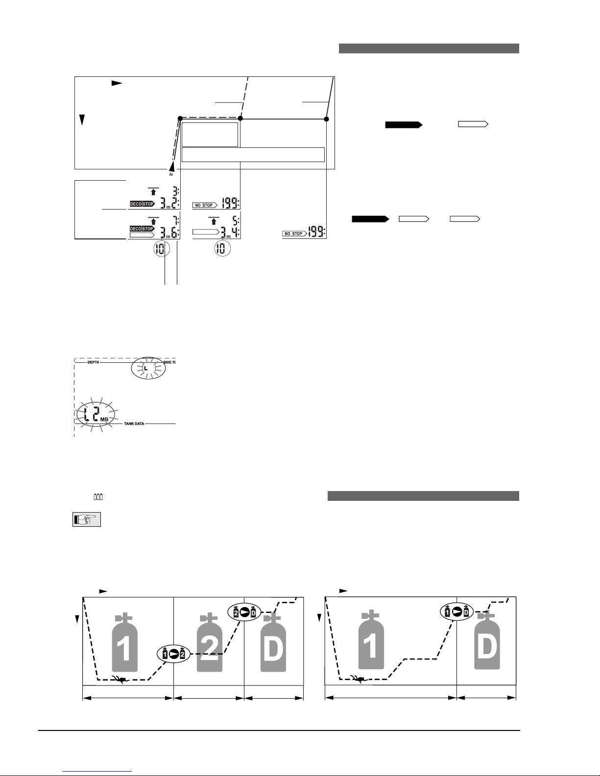
32
4 Functions during the dive with microbubble levels
V/ VI UWATEC®Smart dive computers
5 Complete a dive with MB levels
A dive with MB levels is completed the same way as a dive without MB levels
(L0) (-> 24), save for the following exceptions:
If the MB level has been reduced during the dive, TEC will display a flashing MB
level symbol and the current MB level for five minutes after reaching the surface. The dive is then completed and TEC changes to user mode with the MB
level switching back to the original MB setting.
Repetitive dives and microbubble levels: If during a dive a level stop is being
ignored and the diver starts another descent shortly afterwards, TEC might
immediately request level stops. To complete the dive with the initially set MB
level all level stops must be observed.
4.4 Level stop and deco stop
When the level stop depth equals the
depth of the first obligatory decompression stop and if you are within
1.5m/5feet of the stop depth itself, TEC
shows and . The
indicated duration refers to level stop
duration.
Since level stops are more restrictive
than decompression stops, when all
decompression obligations have been
observed the display changes from
to only.
LEVELSTOP
LEVELSTOP
DECOSTOP
LEVELSTOP
DECOSTOP
Microbubble
level
L0
L5
L0
L5
3m/10ft
Deco stop
duration
Level stop duration
Depth
Time
LEVELSTOP
LEVELSTOP
ft
ft
Level stop duration
decompression stop
depth = level stop depth
VI Diving with more than one gas mixture
VI
The following chapter deals with the characteristics of diving with more than one gas mixture.
Smart TEC enables you to use up to three different gas mixtures during the same dive. To measure the tank
pressure, each tank requires an individual transmitter. Tank 1 contains the bottom mix, tank 2 contains the
travel mix and tank D contains the deco mix. For dives with a single gas mixture you must use tank 1, for
dives with 2 gas mixtures you must use tanks 1 and D.
Diving with 3 gas mixtures Diving with 2 gas mixtures
Bottom mix Travel mix Deco mix
Time
Depth
Bottom mix Deco mix
Time
Depth
Page 33
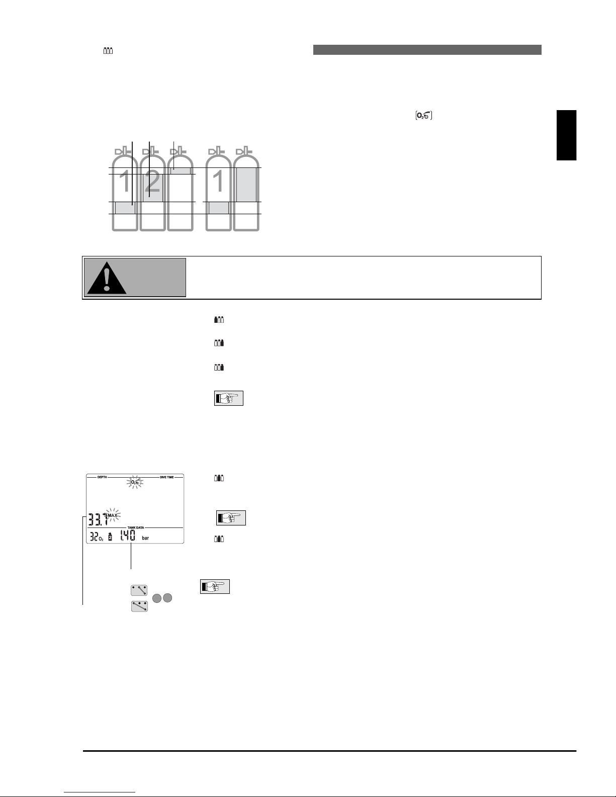
33
VI Diving with more than one gas mixture
VI UWATEC®Smart dive computers
Preparation for a dive with several gas mixtures
Before the dive, all transmitters in use must be paired with TEC, the fraction of oxygen must be entered for
each tank and the depth for changing the gas mixture must be set for tanks 2 and D.
Setting the gas mixture and the depth for changing the gas mixture
During dives with more than one gas mixture the bottom mix
(tank 1) contains the lowest fraction of oxygen, while the deco
mix (tank D) contains the highest fraction.
The additional travel
mix (tank 2) for dives with 3 gas mixtures holds a fraction of
oxygen that is between that of tank 1 and tank D. TEC will only
accept settings corresponding with this order. Note however
that you can also set 2 or even 3 tanks to the same gas mixture.
TEC will only accept gas mixture switching depths (MOD) as
input where the maximum partial pressure of oxygen (ppO
2
), as
pre-set manually (-> 18 point 6) or by means of SmartTRAK, is
not exceeded.
For gas mixtures having an oxygen percentage of 80% or greater the pp
O2is
fixed at 1.6bar and cannot be altered in any way.
Procedure:
1. Enter the setting for the fraction of oxygen and the MOD for tank 1 (bottom mix) according to the instructions on page 18 (points 1-7).
2. Enter the setting for the fraction of oxygen for tank D (deco mix) according to the instructions on page 18 (points 1-5).
3. By bridging B and + or B and – enter the desired depth at which you will
change to tank D during the ascent phase. Confirm your settings with B and E.
The depth you have selected is the Maximum Operating Depth
(MOD) for this gas mixture and the indicated ppO
2
becomes the
maximum tolerable partial pressure of oxygen (ppO
2 max
). During
the ascent an audible attention message will indicate that you
have reached the depth which requires the change of your gas
mixture. This applies to tanks D and 2 (see points below).
4.
For dives with three gas mixtures enter the setting for the fraction of
oxygen for tank 2 (travel mix) according to the instructions on page 18
(points 1-5).
Note that tank symbol 2 can only be selected after tank symbol
D has been assigned to a gas mixture.
5. Now enter the maximum depth for the use of tank 2 by bridging B and
+ or B and -. Confirm your settings with B and E.
The information given under point 3. does apply here also.
Without confirmation with B and E the display will disappear
after 3 minutes and your entries will not be accepted.
The time to reset the O2% mix to air can be set with SmartTRAK between 1 hour
and 48 hours or to "no reset" (default).
After the reset, the oxygen fraction of tank 1 is set to 21%, tanks 2 and D are
switched off (– – %O
2
).
VI
English
100%
O
2
fraction
Range of O
2
fraction
3 gas mixtures
21%
D
2 gas mixtures
D
WARNING
%
Depth for ppO
2
max
change of
gas
mixture,
MOD
+
–
Page 34
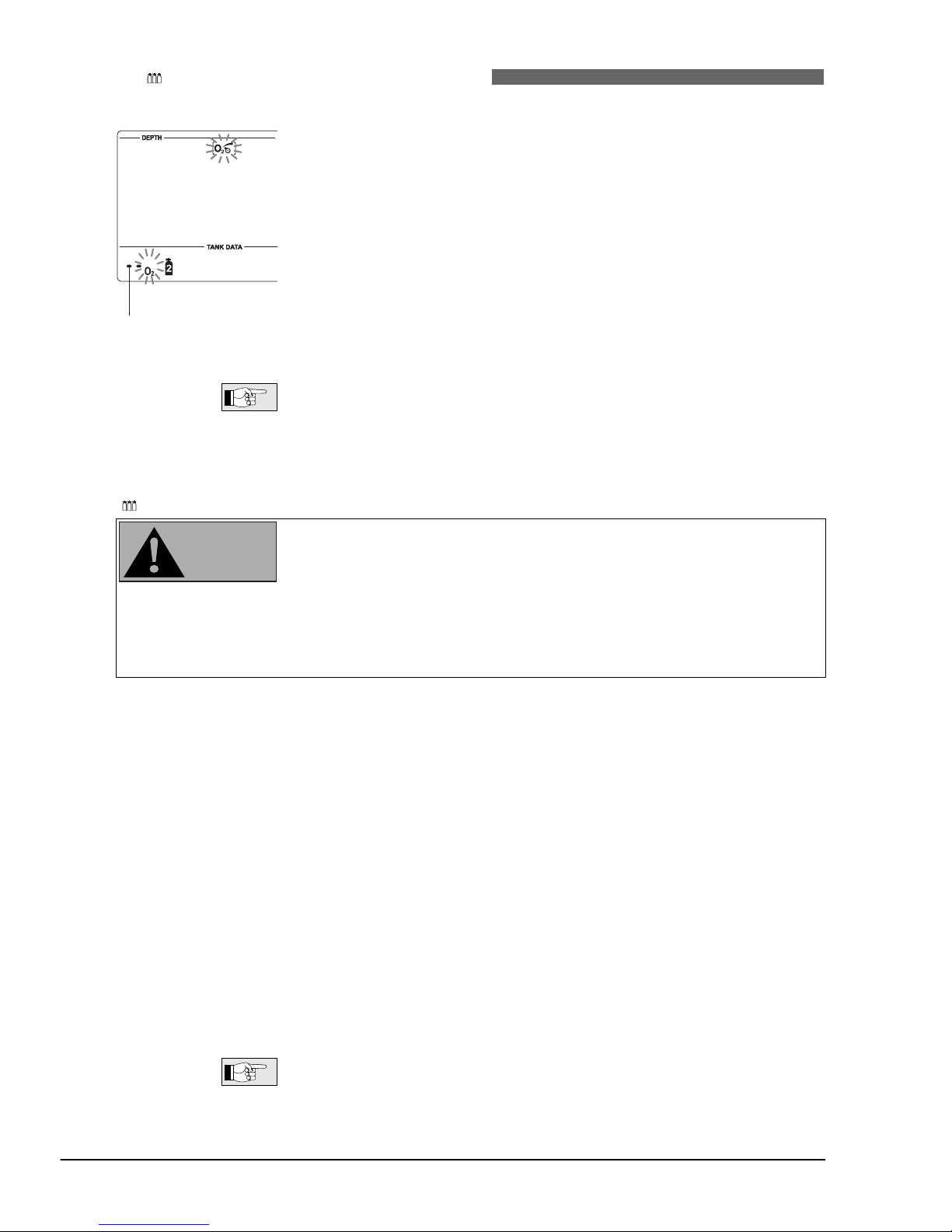
34
VI Diving with more than one gas mixture
VI UWATEC®Smart dive computers
Switching off gas mixtures
Tanks which are not going to be used during the next dive (even though their
fraction of oxygen has been defined) must be "switched off". This is achieved
by switching off the appropriate gas mixture at TEC.
Gas mixtures which have been switched off cannot be selected during the dive
and TEC will ignore their transmitters.
Tank 1 cannot be switched off. If tank D (deco mix) is switched off, tank 2 will
automatically be switched off as well.
Procedure:
1. Select the tank symbol of the gas mixture you wish to switch off and the setting of the O
2
mix, according to the instructions on page 18 (points 1-3).
2. Reduce the fraction of oxygen with B and –, until "– – %O
2
" appears.
3. Confirm your settings with B and E.
The pairing of transmitter and tank symbol will remain valid even if the gas mixture has been shut off.
The selected depth for the change of gas mixture (MOD) is deleted once the
gas mixture is switched off.
Functions during a dive with several gas mixtures
Diving with more than one gas mixture represents a much higher risk (than
diving with a single mixture), and mistakes by the diver may lead to serious
injury or death.
During dives with several gas mixtures, always make sure you are breathing
from the tank you intended to breath from.
Mark all your tanks and regulators, so they can under no circumstances be
mixed up! Before every dive and after changing a tank, make sure that each
gas mixture is set to the correct value for the corresponding tank.
Decompression prognosis
The calculation of decompression data (e.g. the total time of ascent) is based on the assumption that
chan
ges of gas mixture will be performed at the previously selected depths (MOD gas mixture 2, MOD gas
mixture
D). If a diver ignores a required change or changes the mixture belatedly, TEC will readjust the
decompression calculation accordingly. The dive computer will then base its calculations on the assumption
that the diver will either use the indicated gas mixture until he/she reaches the depth for the next
change
or – if no further changes are planned – that
he/she
will ascend to the surface with the current mixture.
Remaining Bottom Time
In addition to calculating the decompression prognosis for all the activated tanks, in the background TEC
also calculates the decompression prognosis for tank 1 by itself, and (when diving with three tanks) for
tanks 1+2 only and for tanks 1+D only. The Remaining Bottom Time (RBT) while breathing from tank 1
considers that you will finish the dive with tank 1, using the decompression prognosis for tank 1 alone.
The RBT while breathing from tank 2 considers that you will finish the dive with tank 2 using the decompression prognosis for tanks 1 and 2 only (see -> 35, 36). This allows, when starting the ascent before
RBT=0, to always be able to finish a dive if by accident you were to lose the travel and/or deco bottles,
find that they are empty or in case of regulator malfunction. Note that for any tank (1, 2 or D) when you
are shallower than 6m/20ft the RBT indicates the duration of the gas supply (minus the reserve) at the current depth.
Since TEC needs to evaluate your breathing pattern and the corresponding
pressure drop in the tank, it takes about 2 minutes after you start breathing
from a tank before TEC shows the RBT.
WARNING
%
Mixture 2
"switched off"
Page 35
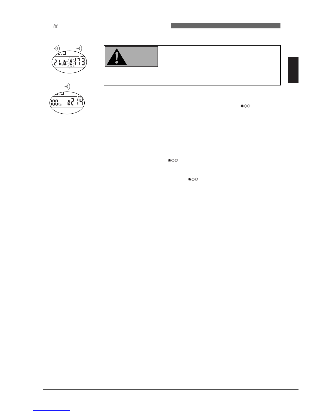
English
35
VI Diving with more than one gas mixture
VI UWATEC®Smart dive computers
VI
No change of gas
mixture:
Belated change of
gas mixture:
Submerging again
after a change
of gas mixture:
%
DECO
STOP
4 sec
oxygen fraction of tank 1
%
DECO
STOP
NO STOP
LEVELSTOP
change of gas mixture
confirmed
Changing the gas mixture
After immersion, TEC automatically selects gas mixture 1.
If during the ascent a diver reaches the depth
requiring a change of gas mixture (MOD gas mixture D or 2), the imminent change is brought to
the diver’s attention by an audible attention signal
and the flashing of the tank symbol of the new
gas mixture, both lasting for 30 seconds.
Procedure: • switch to the regulator with the new gas mixture and start brea-
thing
• confirm the change by pressing and holding (long beep)
within 30 seconds. The tank symbol will stop flashing.
If a diver fails to confirm the change of gas mixture, TEC will continue to calculate with the previous gas mixture and adapt the decompression calculation
accordingly.
A diver can catch up on a required change of gas mixture until he reaches the
surface. By quickly pressing the tank symbol of the new gas mixture will
start flashing.
Switch to the regulator with the new gas mixture and start breathing. Confirm
the change by pressing and holding . The tank symbol will stop flashing
and the decompression calculation will readjust accordingly.
If after a change of gas mixture the Maximum Operating Depth (MOD) of the
current mixture is exceeded, the ppO
2
max warning will appear. ->20
Change to the gas mixture suited for this depth and select the appropriate tank
symbol or rise to the Maximum Operating Depth of the current gas mixture.
Failure to do so can result in oxygen poisoning.
WARNING
…
Examples for clarification of RBT and change of gas mixtures
The following figures show a dive profile and the display of various TECs in the following settings:
1. Start of ascent: the TECs have different decompression prognosis, indicating the benefit of the travel
and/or decompression gases. However, the RBT is the same for all four, as it relates to tank 1 only. It
indicates that starting the ascent within the next three minutes the diver will have enough gas for the
ascent and the decompression obligations shown on TEC-1. At RBT=3 or less, the ascent arrow is showing: TEC suggests that the diver starts the ascent.
2. Slightly below MOD for 50% mix (MOD=22m): The slow ascent has caused significant build-up of
decompression obligations. There is a marked difference in ascent times, indicating the benefit of
decompressing at high oxygen percentage.
3. Above MOD for 50%, missed switch: TEC-2 adjusts its decompression prognosis to be same as TEC-
1. TEC-4 adjusts its decompression prognosis to be the same as TEC-3.
4. Again below MOD for 50%: TEC-2 and TEC-4 once again show credit for the presence of the 50%
mix in their calculations.
5. Above MOD for 50%, switch carried out: TEC-2 and TEC-4 show the tank pressure in the 50% tank.
The RBT agrees because also in TEC-4 it considers the 50% tank will be used to finish the dive. TEC-1
and TEC-3 are not receiving any signals from the transmitter on the 21% tank and show “- - -“.
6. Slightly below the MOD for 100% mix (MOD=6m): During the slow ascent from 22m, TEC-2 using
50% oxygen has caught up on the decompression schedule of TEC-3, which is still using 21% oxygen
but gives credit for the upcoming switch to 100% oxygen.
TEC-1: set to 21% (tank 1)
TEC-2: set to 21% (tank 1) and 50% (tank D)
TEC-3: set to 21% (tank 1) and 100% (tank D)
TEC-4: set to 21% (tank 1), 50% (tank 2) and
100% (tank D)
Page 36
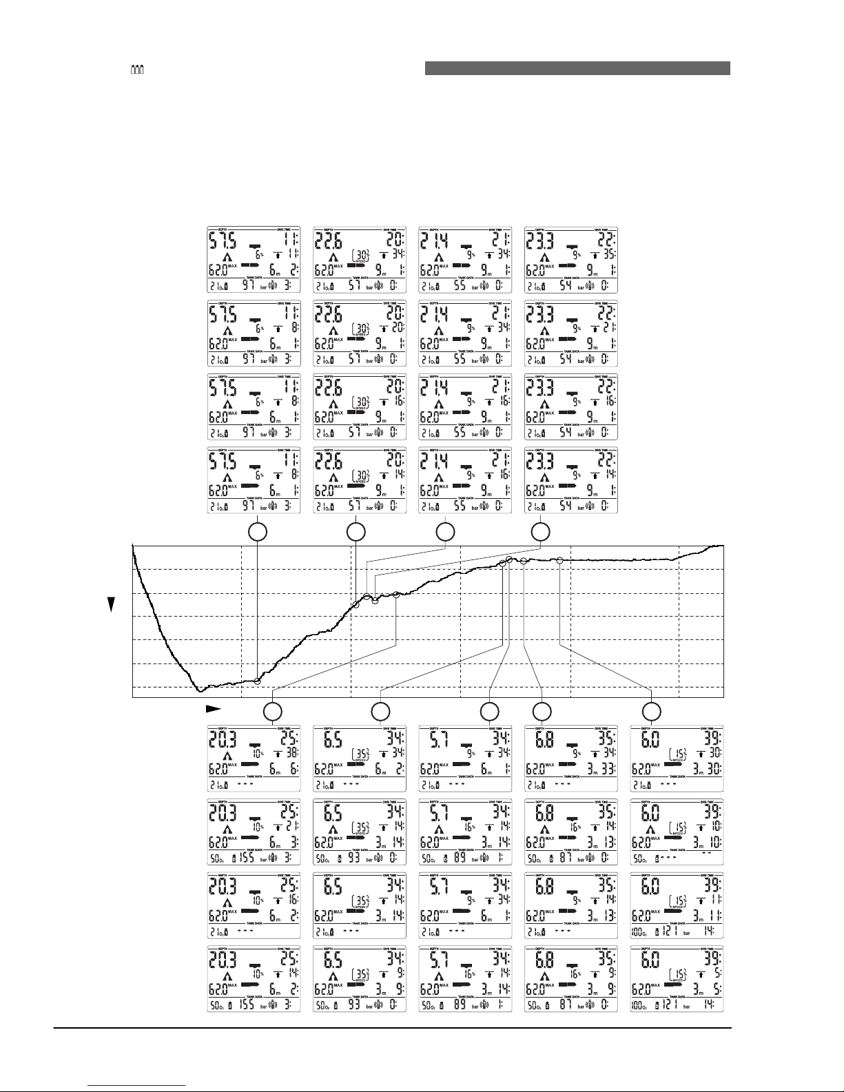
36
VI Diving with more than one gas mixture
VI UWATEC®Smart dive computers
7. Above MOD for 100%, missed switch: now TEC-3 gives the same decompression prognosis as TEC-
1. TEC-4 gives the same decompression prognosis as TEC-2.
8. Again below the MOD for 100%: TEC-3 and TEC-4 again show credit for the presence of the 100%
mix in their calculations
9. Above MOD for 100%, switch carried out: TEC-3 and TEC-4 show the tank pressure in the 100%
tank. The RBT agrees. TEC-2 is not receiving anymore signals from the 50% tank and shows “- - -“.
However, the slow ascent and delayed switch to 100% has caused the decompression prognosis to be
shorter on TEC-2 than TEC-3.
%
DECO
STOP
CNS O2%
%
DECO
STOP
CNS O2%
%
DECO
STOP
CNS O2%
%
DECO
STOP
CNS O2%
%
DECO
STOP
CNS O2%
%
DECO
STOP
%
DECO
STOP
%
DECO
STOP
%
DECO
STOP
%
DECO
STOP
CNS O2%
%
DECO
STOP
CNS O2%
%
DECO
STOP
CNS O2%
%
DECO
STOP
CNS O2%
%
DECO
STOP
CNS O2%
%
DECO
STOP
CNS O2%
%
DECO
STOP
CNS O2%
%
DECO
STOP
CNS O2%
%
DECO
STOP
CNS O2%
%
DECO
STOP
CNS O2%
%
DECO
STOP
CNS O2%
%
DECO
STOP
CNS O2%
TEC-1
21% tank 1
0
10
20
30
40
10
20 30 40 50
0
50
60
Time (min)
Depth (m)
%
DECO
STOP
%
DECO
STOP
%
DECO
STOP
%
DECO
STOP
%
DECO
STOP
CNS O2%
%
DECO
STOP
CNS O2%
%
DECO
STOP
CNS O2%
%
DECO
STOP
CNS O2%
%
DECO
STOP
CNS O2%
%
DECO
STOP
CNS O2%
%
DECO
STOP
CNS O2%
%
DECO
STOP
CNS O2%
%
DECO
STOP
%
DECO
STOP
%
DECO
STOP
%
DECO
STOP
TEC-2
21% tank 1
50% tank D
TEC-3
21% tank 1
100% tank D
TEC-4
21% tank 1
50% tank 2
100% tank D
TEC-1
21% tank 1
TEC-2
21% tank 1
50% tank D
TEC-3
21% tank 1
100% tank D
TEC-4
21% tank 1
50% tank 2
100% tank D
1 2 3 4
5 6 7 8 9
Page 37
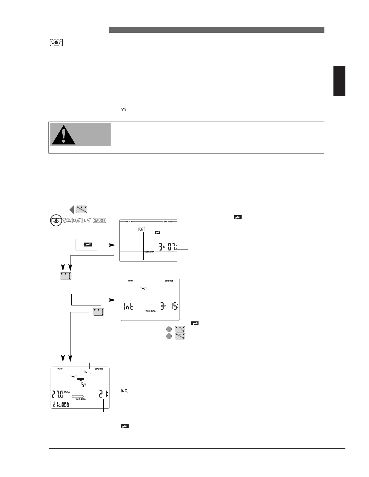
English
37
VII Dive planner
VII UWATEC®Smart dive computers
VII
TEC has a dive planner which allows the planning of no-stop dives as well as decompression dives with
freely determinable surface intervals and with up to three different gas mixtures.
• selected fraction of oxygen and MOD of all active gas mixtures
• selected microbubble level
• water temperature of the most recent dive
• altitude range (if any)
• status of saturation at the time the dive planner is selected
• assuming a normal workload of the diver and observance of the prescribed
ascent rates
• assumption: changes of gas mixture are performed at the selected MOD of
mixtures 2 and D.
If two or more divers using computers are planning a dive, planning for all
divers has to be based on the dive computer showing the shortest no-stop
times. Failure to do this may lead to serious injury or death from decompression sickness.
Before using the dive planner, the fraction of oxygen must be entered for each required tank and the
depths for a change of gas mixture for tanks 2 and D must be entered. Tanks, i.e. gas mixtures which are
not going to be used during the next dive must be switched off (->33-34). All 'activated' gas mixtures will
be indicated by their tank symbols and allowed for calculation.
1 Planning a no-stop dive
With the contacts B and – or B and + you can select the dive planner at the
surface. (The dive planner cannot be selected in gauge mode)
The microbubble warning and
its duration are displayed if
TEC detects an increased risk
due to the accumulation of
microbubbles.
Enter the dive planner with B and E.
The input window for the time interval is displayed
if there was a remaining desaturation (DESAT) before the Dive Planner has been selected. This surface
interval between now and the beginning of the dive
can be changed with the contacts + and – in steps
of 15 minutes.
If a microbubble warning (no dive) and its duration has been displayed, TEC proposes this time –
rounded up to the next 15 minutes – as surface
interval. If the proposed interval is shortened, the
microbubble warning appears.
With B and E you confirm the displayed interval (if applicable), then TEC starts
scrolling the no-stop times. The no-stop times are displayed in 3 metre increments (10 ft) and are displayed for every increment for about 2 seconds. The
process starts at 3 metres (10 ft).
If a microbubble level has been selected (L1-5), the MB no-stop time is
shown.
No-stop times will be displayed as long as the selected maximum operating
depth (MOD) of tank 1 is not exceeded.
On page 24 you will find further information and safety considerations
regarding the microbubble warning.
NO
NO
NO
Input of the
surface interval
%
NO STOP
CNS O2%
Icon for
microbubble
level 1-5
No-stop time or
MB no-stop time
NO
Microbubble warning
(Do Not Dive)
Duration of the
warning
Basis of the planning:
+
–
WARNING
Enter the
dive planner
Dive planner icon
if
NO
if rep. dive
Page 38
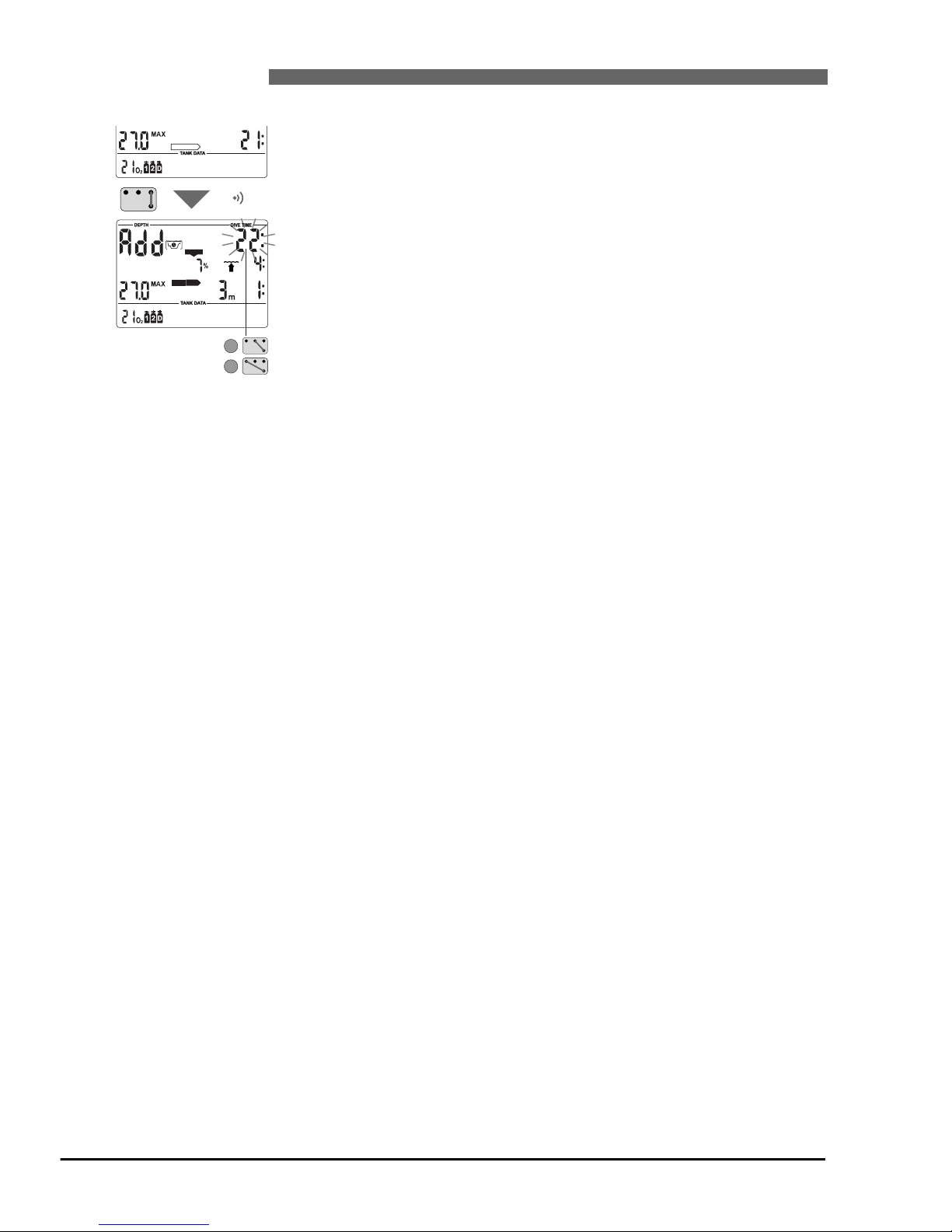
38
VII Dive planner
VII UWATEC®Smart dive computers
%
NO STOP
%
DECO
STOP
CNS O2%
+
–
Bottom Time
2 Planning a decompression dive
1. Activate the dive planner for a no-stop dive ->37.
2. Wait until the desired depth appears, then switch into decompression planning by bridging contacts B and E. TEC shows the bottom time (no-stop time
+ 1 minute) and the appropriate decompression information or level stop
data respectively.
3. <Add> asks that you set the bottom time. This is done with contacts B and
+, B and – respectively. As soon as the contacts are no longer bridged, TEC
calculates the decompression information or level stop data respectively for
this set bottom time.
If you wish to plan a decompression dive at another depth, switch from decompression planning to no-stop planning by means of B and E. TEC again shows
the scrolling no-stop times. Now you can switch between no-stop planning and
decompression planning at will with contacts B and E.
If the calculated decompression information and the total ascent time exceed
199 minutes, or the CNS O
2
% value exceeds 199%, the said values will start
flashing on the display or <– –> values appear and the decompression calculation is suspended until the bottom time has been reduced accordingly. CNS
O
2
% values higher than 199% will be displayed as 199 %.
3 Leaving the dive planner
With the contacts B and E (1-2 sec) you can exit the Dive Planner. This also
occurs after three minutes without operation.
Page 39
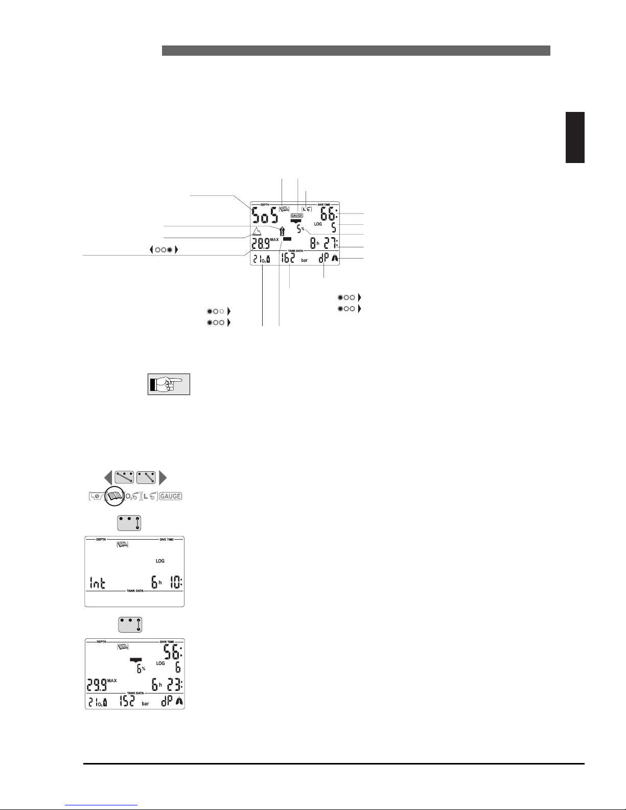
English
39
VIII Logbook
VIII UWATEC®Smart dive computers
VIII
2 Operation
With the contacts B and + or B and – you can select the logbook. With B and
E you enter the logbook.
If there was a remaining desaturation time (DESAT) before selecting the logbook, the time since the last dive (surface interval) is displayed.
With B and E you get the most recent dive displayed (LOG 1).
Each bridging of B and + or B and – causes a jump to the next older or more
recent dive. Upon continuous bridging of the contacts all dives are displayed
successively.
With the contacts B and E you can exit the logbook.
The logbook closes automatically after 3 minutes without operation.
%
CNS O2%
1 Survey
A dive is entered in the logbook if the dive time is longer than 2 minutes. TEC records the profiles of about
100 hours of diving. This information can be transferred to a PC with the standard infrared interface (IrDA)
and the Windows
®
software SmartTRAK. Up to 99 dives can be displayed directly on the dive computer.
The following information of the dive is displayed:
If a dive is started within adaptation time (after a change of altitude), the
adaptation time is displayed instead of the surface interval.
%
CNS O2%
Ignored decompression stop* or
diving in SOS mode
Logbook icon
MB level reduced*
*Alarms during the dive
Dive time
Dive number
Duration of surface interval (only with repetitive dives)
Gas consumed (bar or psi) from tank 1
" tank 2
" tank D
(displays only those gas
mixtures used during the dive)
DECO
Too fast ascent*
Ignored decompression stop*
Fraction of oxygen tank 1
" tank 2
" tank D
Altitude range (if any)
CNS value at the end of the dive
Maximum depth / Lowest temp. / MB level
(at the beginning of the dive)
Increased workload warning*
dP = differential pressure (gas consumed)
Diving in gauge mode
Page 40
40
IX Appendix
XI UWATEC®Smart dive computers
1 Technical information
Operating altitude: with decompression information: sea level up to approx. 4000 m (13120ft);
w/o decompression, w/o RBT information: usable in gauge mode (at any altitude)
Max. displayed depth: 120m (395 ft), resolution between 0.8 m and 99.9 m: 0.1 m, >99.9 m: 1m
The resolution in feet is always 1 foot
• Do not dive deeper than the limits given by the chosen fraction of oxygen
(nitrogen narcosis, oxygen toxicity).
• Never dive deeper than your training qualification (experience) allows you.
• Always observe local dive depth restrictions.
Decompression calculation depth range: 0.8 to 120m (3 to 395 ft)
Maximum environment pressure: 13 bar (189 psi)
Clock: Quartz timer, display up to 999 minutes.
O
2% Mix: Adjustable between 21%O2 (compressed air) and 100% O2
Operating temperature:
-10° to +50°C (14°F to 122°F).
Power supply: Special battery UWATEC LR07
Life of the battery: 500 to 800 dives, depending on the quantity of dives per year and the use of
the backlight.
Transmitter: High pressure connection: Maximum working pressure: 300 bar (4350 psi)
Life of the battery: up to 1000 dives, max. 3 years without use.
Power supply: User replaceable battery CR2450
2 Maintenance
The tank pressure gauge and the parts of this product used to measure the tank pressure should be serviced
by an authorized SCUBAPRO UWATEC dealer every second year or after 200 dives (whichever comes first).
Aside from that your TEC is virtually maintenance free. All you need to do is to rinse it carefully with fresh
water after each use and to have the batteries changed when needed. To avoid possible problems with your
TEC, the following recommendations will help assure that it will give you years of trouble free service:
• Avoid dropping or jarring your TEC.
• Do not allow your TEC to be exposed to direct, intense sunlight.
• Rinse your TEC thoroughly with fresh water after each dive.
• Do not store your TEC in a sealed container; make sure there is free ventilation.
• If there are problems with operating the contacts, use soapy water to clean
TEC and dry it thoroughly. The surface of your TEC housing can be treated
with
silicone grease. Do not apply grease to the water contacts!
• Do not clean TEC with liquids containing solvent (apart from water).
• If the service icon appears, TEC must not be used for any further dives. Take
your dive computer to an authorized SCUBAPRO UWATEC dealer.
Take the dive computer to an authorised SCUBAPRO UWATEC dealer in order
to change the batteries. The battery replacement is carried out by a SCUBAPRO UWATEC
subsidiary. TEC is checked for its technical integrity
at the same
time. Do not attempt to have the batteries changed by anyone other than an
authorised SCUBAPRO UWATEC dealer.
2.1 Replacing the battery of the transmitter
It is recommended to have the battery of the transmitter replaced by an
authorized
SCUBAPRO UWATEC dealer. The change must be made with particular care in order to prevent water from seeping in.
The warranty does not cover damages due to an improper replacement of the
battery.
Transmitter battery set (PN 06.201.920): Includes a Type CR 2450 battery and a 26.00 x 2.00 mm trans-
mitter cap o-ring .
WARNING
WARNING
WARNING
WARNING
Page 41
41
IX Appendix
IX UWATEC®Smart dive computers
Never touch the metal surface of the battery with bare fingers.
The two battery poles must never be short circuited.
Procedure:
To replace the battery you need a Phillips screwdriver and a clean cloth.
• A leaking transmitter cap may lead to the destruction of the transmitter by
water seeping in or cause the transmitter to switch off without prior notice.
• Always open the transmitter in a dry and clean environment.
• Only open the transmitter to replace the battery.
1. Remove the transmitter from the HP outlet of the first stage of the regulator.
2. Dry the transmitter with a soft towel.
3. Remove the 3 screws with the Phillips screwdriver.
4. Remove the transmitter cap carefully.
5. Remove the transmitter cap o-ring carefully. Do not damage the sealing surfaces.
6. Remove the battery by holding it on both sides. Do not touch the contacts or electronic
parts.
Protect the environment and dispose the battery properly.
If you notice traces of seeping water, damages, or other defects on the o-ring,
do not use the transmitter for further dives. Take it to an authorized SCUBAPRO UWATEC dealer for check and repair.
7. Always insert a new o-ring when you replace the battery and dispose the old o-ring.
Make sure that the new, lubricated o-ring is in perfect condition, and that o-ring, o-ring groove and
the sealing surfaces of HP outlet and transmitter cap are free of dust and dirt.
If necessary, clean the parts with a soft cloth. Fit the o-ring in the o-ring groove.
8. Check the proper polarity of the battery. The transmitter can be damaged
if you do not insert the battery correctly.
Wait for at least 30 seconds. Now insert the new battery, with "+" pointing upwards, into the battery
compartment.
9. After battery replacement the transmitter will perform an automatic test and switch into ready mode
after 60 seconds.
IX
English
WARNING
WARNING
WARNING
WARNING
HP port o-ring
8.73 x 1.78 mm
Transmitter screws
PT
®
KA 30 x 16 mm
Transmitter cap o-ring
26.00 x 2.00 mm
Transmitter Battery
CR2450
Transmitter Cap
Page 42
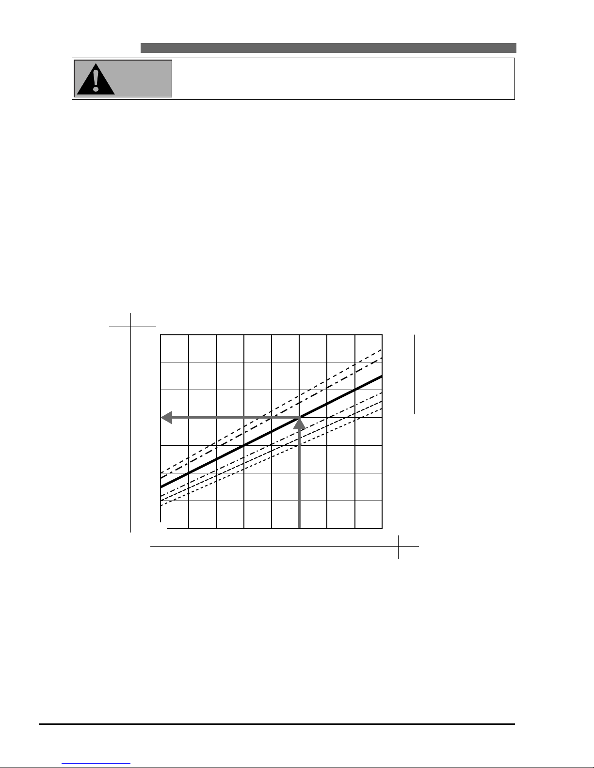
42
IX Appendix
IX UWATEC®Smart dive computers
4 Warranty
The warranty only covers dive computers which have been bought from an authorised SCUBAPRO
UWATEC retailer.
The warranty is given for a period of 2 years.
Repairs or replacements during the warranty period do not increase the warranty period.
In order to put forward a warranty claim: send the dive computer together with a dated receipt of the
purchase to your authorised retailer or an authorised servicing point.
UWATEC reserves the right to determine the merits of a warranty claim and to determine whether the
computer will be repaired or replaced.
3 Conversion of tank pressure
Tank pressure indicated may differ from the information given by a manometer/pressure gauge. TEC displays pressure always converted to a temperature of 20°C / 68°F, whereas the mechanical pressure gauge
displays the current pressure influenced by temperature.
The figure below allows you to compare the information given by a conventional pressure gauge and by
TEC at six different temperatures.
260
240
220
200
180
160
140
120
150 160 170 180 190 200 210 220 230 bar
35
o
C
30
o
C
20
o
C
10
o
C
5
o
C
0
o
C
Display Smart TEC
Display pressure gauge
3770
3480
3190
2900
2610
2320
2030
1740
psi
bar
95
o
F
86
o
F
68
o
F
50
o
F
41
o
F
32
o
F
2175 2320 2465 2610 2755 2900 3045 3190 3335 psi
10.
The transmitter cap will only fit in one position. Check the proper position
of the guide slots on the electronic support and in the transmitter cap.
Slide the transmitter cap carefully back into its proper position.
11. Do not overtighten the screws! Fasten the transmitter cap with the 3 screws.
12. Mount the transmitter on the HP outlet of the first stage of the regulator and check transmission and
pairing. If you do not receive valid tank pressure data, transmitter and dive computer must be paired
again.
WARNING
Page 43

English
Active backlight___________________________11
Ascent rate________________________15, 17, 19
Battery alarm _____________________________17
Battery capacity, Checking the… ____________10
Battery lifetime ___________________________40
Beep, Switch off the…_____________________17
Changing the gas mixture ______________26, 34
CNS O
2________________2, 3, 15, 16, 17, 21, 39
Deco data during decompression phase ______15
Deco data during no-stop phase ____________15
Decompression stop, Ignored… __________17, 23
Depth, current____________________________19
Desaturation time _________________________24
Dive ____________________________________15
Dive planner _____________________________37
Dive time ________________________________19
Dive, end of a dive ________________________24
Fly, "no-fly time" ______________________10, 24
Gas mixture, Setting…_____________________18
Gauge mode _____________________________26
Light ____________________________________11
Logbook_________________________________39
Maintenance _____________________________40
Maximum depth_______________________19, 39
Microbubbles_____________________________28
Microbubbles, Warning of… ____________24, 37
Mountain lakes, Diving in… ____________25, 39
Mounting the transmitter to the first stage ___12
Nitrox ______________________________16
43
IX Appendix
iX UWATEC®Smart dive computers
IX
No-stop time ______________________15, 22, 28
O2% mix, Set up… ________________________18
O
2 fraction ________________________15, 16, 18
O2 partial pressure__________________16, 17, 20
O2 partial pressure, maximum ___________16, 20
O2 toxicity __________________15, 16, 17, 21, 39
Operating TEC ________________________4, 8, 9
Oxygen…, see "O
2…"
PC, transfer to PC (logbook) ________________39
ppO
2, see O2 partial pressure
Premix, setting the gas mixture______________18
RBT ______________________________15, 17, 22
Safety stop timer__________________________23
Setting the MOD ______________________18, 33
SmartTRAK ___________________8, 9, 16, 17, 39
SOS mode _______________________________11
Stopwatch _______________________________27
Surface interval________________________37, 39
Switching off gas mixtures__________________34
System ___________________________________8
Tank pressure ____________________________21
Technical information ______________________40
Transmitter _________________________8, 12, 40
Warnings ________________________________17
Workload _______________________________21
Workload, Increased… ____________________ 21
6 Index
Excluded are faults or defects due to:
• excessive wear and tear;
• exterior influences, e.g. transport damage, damage due to bumping and hitting, influences of weather
or other natural phenomena;
•
servicing, repairs or the opening of the dive computer by anybody not authorised
by the manufactu-
rer. This especially concerns the change of battery;
• pressure tests which do not take place in water;
• diving accidents;
• improper placement of the transmitter cap.
5 FCC
This device complies with part 15 of the FCC Rules. Operation is subject to the following two conditions:
(1) This device may not cause harmful interference, and (2) this device must accept any interference
received, including interference that may cause undesired operation.
Page 44

UWATEC®Smart dive computers
SCUBAPRO UWATEC Americas
(USA/Canada/Latin America)
1166 Fesler Street
El Cajon, CA 92020 USA
t: +1 619 402 1023
f: +1 619 402 1554
www.scubapro.com
SCUBAPRO UWATEC Asia Pacific
1208 Block A, MP Industrial Center
18 Ka Yip St.
Chai Wan Hong Kong
t: +852 2556 7338
f: +852 2898 9872
www.scubaproasiapacific.com
SCUBAPRO UWATEC Australia
Unit 21, 380 Eastern Valley Way
Chatswood, N.S.W. 2067
t: +61 2 9417 1011
f: +61 2 9417 1044
www.scubapro.com.au
SCUBAPRO UWATEC Deutschland
(Germany / Austria / Scandinavia)
Taucherausrüstungen GmbH
Rheinvogtstraße 17
79713 Bad Säckingen-Wallbach
t: +49 (0) 7761 921050
f: +49 (0) 7761 921051
www.scubapro.de
SCUBAPRO UWATEC Italy
Via G.Latiro 45
I-16039 Sestri Levante (GE)
t: +39 0185 482 321
f: +39 0185 459 122
www.scubapro.it
SCUBAPRO UWATEC Japan
4-2 Marina Plaza 5F
Kanazawa-Ku
Yokohama
Japan
t: +81 45 775 2288
f: +81 45 775 4420
www.scubapro.co.jp
SCUBAPRO UWATEC France
Les Terriers Nord
175 Allée Belle Vue
F-06600 Antibes
t: +33 (0) 4 92 91 30 30
f: +33 (0) 4 92 91 30 31
www.scubapro-uwatec.com
SCUBAPRO UWATEC Benelux
Avenue des Arts, 10/11 Bte 13
1210 Bruxelles
t: +32 (0) 2 250 37 10
f: +32 (0) 2 250 37 11
www.scubapro-uwatec.com
SCUBAPRO UWATEC España
Pere IV, nº359, 2º
08020- Barcelona
t: +34 93 303 55 50
f: +34 93 266 45 05
www.scubapro-uwatec.com
SCUBAPRO UWATEC U.K.
Vickers Business Centre
Priestley Road
Basingstoke, Hampshire RG24 9NP
England
t: +44 0 1256 812 636
f: +44 0 1256 812 646
www.scubapro.co.uk
SCUBAPRO UWATEC Switzerland
Oberwilerstrasse 16
CH-8444 Henggart
t: +41 (0) 52 3 16 27 21
f: +41 (0) 52 3 16 28 67
www.scubapro.de
www.uwatec.com
9.04
 Loading...