


Copyright © 2018 UUGear s.r.o. All rights reserved.
Zero2Go Omini
Wide Input Range, Multi-Channel Power supply for Raspberry Pi
User Manual (revision 1.01)

Copyright © 2018 UUGear s.r.o. All rights reserved.
Table of Content
Product Overview .............................................................................................. 1
What is in the Package? .................................................................................... 3
Zero2Go Omini Specifications ........................................................................... 4
Software Installation .......................................................................................... 5
Software Update/Uninstallation .......................................................................... 6
Mounting Zero2Go on Raspberry Pi Zero .......................................................... 7
Mounting Zero2Go on Other Raspberry Pi Models ............................................ 8
Connecting Power Supplies ............................................................................. 10
Software Usage ................................................................................................ 11
1. Set Default State .............................................................................. 12
2. Set Blinking Interval ......................................................................... 12
3. Set Power Cut Delay ........................................................................ 12
4. Set Low Voltage Threshold............................................................... 12
5. Set Recovery Voltage Threshold ...................................................... 13
6. Set Step-Down Engine Always-On ................................................... 13
7. Exit ................................................................................................... 14
Ghost Voltage .................................................................................................. 14
Work as Uninterruptible Power Supply (UPS) .................................................. 15
Hardware Hackings ......................................................................................... 15
1. Interface with different Power Supplies ............................................ 15
2. Change the Pin Used by Zero2Go Omini ......................................... 17
3. Modify and Upload Firmware............................................................ 18
Zero2Go Omini Log Files ................................................................................. 19
Frequently Asked Questions (FAQ) ................................................................. 20
1. What I2C Address is Used by Zero2Go Omini? ................................ 20
2. What I2C Registers Are Provided by Zero2Go Omini? ...................... 20
3. What GPIO Pins Are Used by Zero2Go Omini?................................ 23
4. Is Zero2Go Omini Compatible with “Other Hardware”? .................... 24

Copyright © 2018 UUGear s.r.o. All rights reserved.
5. How to Understand the Color of LED on Zero2Go Omini? ............... 24
Revision History............................................................................................... 26
1
Product Overview
Zero2Go is a Raspberry Pi Zero sized (or pHAT shape) extension board that can work
as wide input range power supply for Raspberry Pi. Zero2Go Omini is the second
member in the Zero2Go family.
Zero2Go Omini supports all Raspberry Pi models that has the 40-pin GPIO header,
including A+, B+, 2B, 3B, 3B+, Zero and Zero W.
The main features of Zero2Go Omini include:
Three separated input channels (each accepts 3.5~28V DC).
Auto step-up or step-down to output 5V for powering Raspberry Pi.
Auto switch input channel (one with highest voltage takes the priority).
Gracefully turn on/off Raspberry Pi with single tap on the button.
Fully cuts power for Raspberry Pi and all its USB peripherals after shutdown.
Long hold the button to force power cut, when OS loses response.
Monitor the input voltage on each channel (via software).
Shutdown Raspberry Pi when input voltage below preset threshold.
Recover Raspberry Pi when input voltage exceed preset threshold.
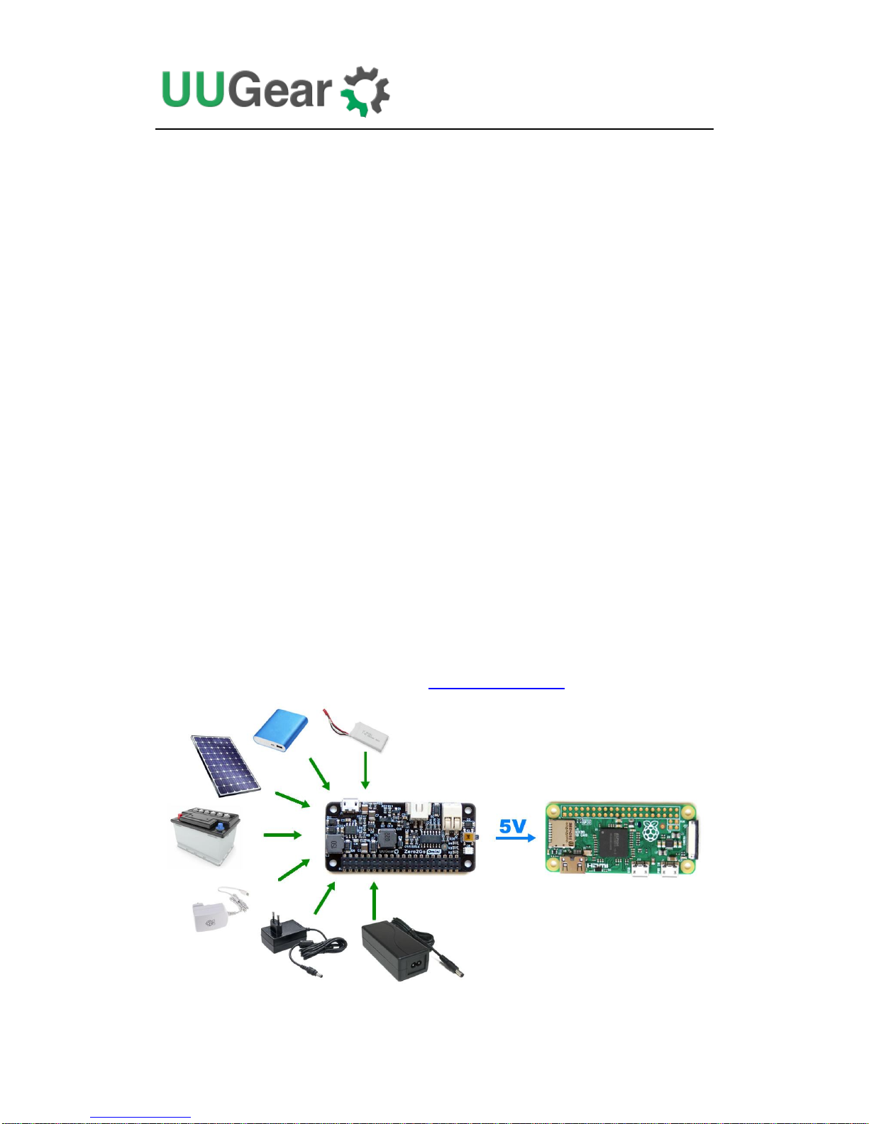
Zero2Go has quite wide input range (3.5V~28V), so it is convenient to power your
Raspberry Pi with power bank, Li-Po battery pack, solar panel, car battery or different
kinds of power adapters etc. You can also configure it as a UPS.

2
The board size of Zero2Go is exactly the same with Raspberry Pi Zero (W), and can
be mounted on Raspberry Pi Zero or other Raspberry Pi models that have 40-pin
header.
How does it work? Please see below the simplified diagram. It demonstrates the main
functionalities of Zero2Go Omini and can help you to understand how it works.
Three input channels (A, B and C) are merged as Vin with 3 schottky diodes. The
comparator will compare Vin with an internal reference and decide whether to use
step-up or step-down engine. When Vin is lower than 5.5V, the step-up engine will be
used; When Vin is 5.5V or higher, the step-down engine will be used instead. The
outputs of both engines are also merged with 2 schottky diodes.
The voltage on each input channel can be measured by ADC (analog-to-digital
converter) and the result can be queried via I2C interface.
Zero2Go Omini also has built-in low-voltage protection, which can gracefully
shutdown your Raspberry Pi when input voltage is too low. This feature can be
enabled via Zero2Go Omini Console. Please read Software Usage chapter for more
information.

3
The picture below shows how Zero2Go Omini looks like:
1) Micro USB connector for input channel A
2) XH2.54-2P connector for input channel B
3) Universal wire connector for input channel C.
4) Tact button to turn on/off Raspberry Pi.
5) Three-color LED (red, green, blue) as action indicator.
6) 2x20-pin header (connects to Raspberry Pi).
What is in the Package?
Each Zero2Go Omini package contains:
Zero2Go Omini board x 1
M2.5 x 10mm plastic screw x 4
4mm spacer x 4
M2.5 plastic nut x 4

4
Zero2Go Omini Specifications
Dimension:
65mm x 30mm x 7.7mm
Weight
12g (net weight)
Mainly Used Chips
MCU: ATtiny841 (datasheet)
DC-DC Bulk: MP4462 (datasheet)
DC-DC Boost: SDB628 (datasheet)
LED Indicator
Three-color LED (red, green and blue)
Interface
Micro USB female connector for input channel A.
XH2.54-2P connector for input channel B.
Universal wire connector for input channel C.
20x2 header (h=2mm) for connecting Raspberry Pi.
Input
Three separated channels (A, B, and C)
All accept DC 3.5V~28V (5.5~7.0V is not recommended
as the DC-DC converter needs more dropout to work well)
Output
Output 5V (±5%), maximum 2A
Efficiency
Up to 87% @ Step-Up mode
Up to 82% @ Step-Down mode
Standby Current
~0.13mA @ Vin=3.5V
~0.36mA @ Vin=12V
~0.87mA @ Vin=28V
Operating Temperature
-30℃~80℃ (-22F~176F)
Storage Temperature
-40℃~85℃ (-40F~185F)
Humidity
0~80%RH, no condensing

5
Software Installation
We strongly recommend to install the software before physically mount Zero2Go
Omini on your Raspberry Pi.
You will need to have your Raspberry Pi connected to the Internet. The installation
will be very simple if you run our installing script. The wiringPi utility is required by
the software so the script will install it for you, if you haven’t done so before.
First step is to run this command in your home directory:
If your Raspberry Pi has internet connection, it will immediately download the script
from our website, and you will then see the “installZero2Go.sh” script in your home
directory. You can then run it with sudo:
Please notice that sudo is necessary to run this script, because it will copy file to the
/etc/init.d/ directory as well. This script will automatically do these tasks in sequence:
1. Enable I2C on your Raspberry Pi
2. Install i2c-tools, if it is not installed yet
3. Configure Bluetooth to use mini-UART
4. Install wiringPi, if it is not installed yet
5. Install Zero2Go programs, if they are not installed yet
You can also manually install these packages and make those configurations, if you
prefer to. After the installation, please remember to reboot your Raspberry Pi.
You will see a new “zero2go” directory, and it contains 2 runnable files:
pi@raspberrypi ~ $ wget http://www.uugear.com/repo/Zero2GoOmini/installZero2Go.sh
pi@raspberrypi ~ $ sudo sh installZero2Go.sh
pi@raspberrypi ~ $ cd zer2go
pi@raspberrypi ~ /zero2go $ ls
daemon.sh init.sh utilities.sh zero2go.sh

6
Although the daemon.sh is runnable, you should not run it manually. The installing
script has registered it into /etc/init.d and it will run automatically after the boot.
The zero2go.sh is the software that allows you to monitor the working status of
Zero2Go and make configuration interactively. Please see the “Software Usage”
chapter for more information.
Now the software has been installed, and you will need to physically mount Zero2Go
Omini on your Raspberry Pi.
Software Update/Uninstallation
If you want to update the software to newer version, you don’t have to uninstall it
first. Just remove or rename your “zero2go” directory and repeat the installing
process, then you are all set.
If you prefer to completely remove the software, besides removing the “zero2go”
directory, you should also remove the “/etc/init.d/zero2go_daemon” file. There are
some dependencies (such as wiringPi, i2c-tools etc.), who are installed during the
software installation. In the majority of cases you don’t have to remove them, but if
you wish, you can check the content of “installZero2Go.sh” script and do the reverse.
pi@raspberrypi ~ $ mv zero2go zero2go.bak
pi@raspberrypi ~ $ wget http://www.uugear.com/repo/Zero2GoOmini/installZero2Go.sh
pi@raspberrypi ~ $ sudo sh installZero2Go.sh

7
Mounting Zero2Go on Raspberry Pi Zero
If you want to use Zero2Go Omini on Raspberry Pi Zero (V1.2, V1.3 or W), you will
need to solder the 20x2 pin male header (not included in the package) on it first, or
you can buy one with the header pre-soldered.
You can simply mount Zero2Go Omini on your Raspberry P Zero’s 40-pin header,
and it can work immediately. However, if you wish, you can use the plastic screws,
spacers and nuts (included in the package) to tightly mount Zero2Go Omini on your
Raspberry Pi Zero. Please make sure NOT to put Zero2Go up side down, the 40 pins
should connect to the female header via the holes underneath, as shown in figure
below.

8
Mounting Zero2Go on Other Raspberry Pi Models
Other Raspberry Pi models (A+, B+, 2B and 3B) have the 40 pin header pre-soldered
already, so it is possible to directly mount Zero2Go Omini over them. However,
because of the existence of display connector, you may not be able to firmly connect
them.
In order to make reliable connection, we suggest to use a stacking pin header (not
included in the package).
The 40 extra long pins on stacking header should reach the female header via the
holes on the back of Zero2Go Omini. You can then place a steel ruler (or something

9
similar) between the two rows of pins and push Zero2Go Omini until it reaches the
plastic of the stacking header, as shown in figure below:
If you want to take off the stacking header from Zero2Go Omini, the proper way is to
put your Zero2Go Omini upside down, and let the 40 pins contact a flat surface (e.g.
the desktop), hold the two edges and press the board down. That way the stacking
header will be taken off safely. See the figure below:

10
Connecting Power Supplies
Zero2Go Omini has 3 separated input channels, and you can connect multiple power
supplies at the same time (one power supply per channel).
If multiple power supplies present, the one with highest voltage will take effect. If that
power supply is turned off, the one with second highest voltage will take its place.
The diagram below explains how this happens:
In Zero2Go Omini, these diodes (D1, D2 and D3) are high current schottky diodes.
Thanks to them, the input channels are separated, and they all have reverse polarity
protection.
Each input channel can accept 3.5V~28V DC. If there is at least one input channel has
enough voltage, you will see the LED indicator blinking in red, which means it is
standing by.
Remarks: when connecting power supply with rather high voltage (> 12V), please
turn off the power supply until the reliable connection has been made. Otherwise the
inrush current could damage the hardware!

11
After your Raspberry Pi is up, you can run the software and monitor the voltages on
these three input channels. Please read Software Usage chapter to learn more.
It is possible to configure Zero2Go Omini as an Uninterruptible Power Supply (UPS),
please read the Work as Uninterruptible Power Supply (UPS) chapter for more
details.
Software Usage
You can run the zero2go.sh bash script to launch the Zero2Go Omini console:
The Zero2Go Omini console looks like this:
In the “Status” area you can read the current voltage of each input channel, and know
what the current working mode is (step-up or step-down). The whole interface will be
refreshed for every 5 seconds.
In the “Menu” area you can make some configurations on your Zero2Go Omini.
pi@raspberrypi ~/zero2go $ ./zero2go.sh
ZERO2GO OMINI CONSOLE
V1.00 by UUGear s.r.o.
Status
Channel-A: 4.75V Channel-B: 0.40V Channel-C: 0.40V
Working Mode: Step-Up
Menu
1. Set default state when power is connected: [Default Off]
2. Set blinking interval when standing by: [4 Seconds]
3. Set delay between shutdown and cutting power: [5.0 Seconds]
4. Set low voltage threshold: [Disabled]
5. Set recovery voltage threshold: [Disabled]
6. Set step-down engine always-on: [No]
7. Exit
Enter your choice (1~7)

12
1. Set Default State
By default, your Zero2Go will not turn on your Raspberry Pi when power supply is
connected, and you will need to tap on the button to boot your Raspberry Pi. This
means “Default Off”.
If you change it to “Default On”, Raspberry Pi will be turned on automatically when
power supply is connected. A typical use case is that you wish Raspberry Pi to get
back to work after a power failure.
2. Set Blinking Interval
Zero2Go is in “stand by” state when power supply is connected, and Raspberry Pi is
not turned on yet. In this state the LED will blink in red color with a fixed interval,
whose default value is 4 seconds (blink once per 4 seconds).
Here you can choose 1, 2, 4 or 8 seconds. Since Zero2Go uses watchdog timer to
wake itself up and blink the LED, this interval can not be set to other values due to the
limitation of watchdog timer.
3. Set Power Cut Delay
After the operational system has been shut down, the TXD pin on Raspberry Pi will
go to LOW state, and Zero2Go will wait for a few seconds and then cut the power for
Raspberry Pi.
Here you can choose the delay between system shutdown and the power cutting. The
default value is 5.0 seconds, and you can choose any value from 0.0 to 8.0 seconds
(numbers with one decimal digit are supported).
4. Set Low Voltage Threshold
Zero2Go Omini allows you to specify a voltage threshold, that when all input voltages
are below this threshold, Zero2Go will suggest Raspberry Pi to shutdown (by pulling
down GPIO-4 for a moment).
This threshold is disabled by default. Here you can specify 2.0~25.0 volts as the
threshold (numbers with one decimal digit are supported). You can disable this
threshold again by inputting 0 here.

13
5. Set Recovery Voltage Threshold
Here you can also specify a voltage threshold, that when any of input voltage exceeds
this threshold, Zero2Go will turn on your Raspberry Pi. This behavior will happen
only when your Raspberry Pi was shut down due to the low voltage (see the “Set Low
Voltage Threshold” section above). If low voltage threshold is disabled, configuration
of this recovery voltage threshold will be ignored.
This threshold is disabled by default. Here you can specify 2.0~25.0 volts as the
threshold (numbers with one decimal digit are supported). You can disable this
threshold again by inputting 0 here.
It is recommended to configure this threshold to a value higher than the “low voltage
threshold”. Otherwise you may encounter “shutdown - startup” infinite loop. For
example, assume you are using a single-cell Li-Po battery to power Zero2Go. If you
configure the low voltage threshold to 3.0V, you can configure the recovery voltage
threshold to 4.2V. So the system will shutdown when the battery is running out, and
get back to work when the battery gets fully charged.
6. Set Step-Down Engine Always-On
Zero2Go Omini uses two DC-DC converting engines at the same time: one for
step-up (boost) and one for step-down (bulk).
Usually only one engine is activated at a time. When input voltages are all below
5.5V, the step-up engine is on; When any input voltage exceeds 5.5V, the step-down
engine will be activated, while the step-up engine will be off.
However, starting an engine will take some time and switching between engines may
cause the interrupt of output voltage. For example, assume the input voltage from
3.7V drops to 7.4V, the step-up engine will be turned off and the step-down engine
will be on. The output voltage will be lost when step-up engine is off, while the
step-down engine has not been initialized yet, thus the output voltage will be
interrupted. If Raspberry Pi is running, it will lose the power for a moment and most
probably will be rebooted.
That’s why we have this configuration here, which allows you to turn the step-down
engine always-on, so it can start working in no time. Don’t worry, turning step-down
engine always-on only cost a small current (about 0.1mA) because the step-down
engine is still disabled when input voltages are lower than 5.5V.
You may ask, why there is no option to turn the step-up engine always-on? It is
because the step-up engine does not isolate the input and output (they are coupled via
an inductor), so the voltage will reach the output as long as the step-up engine is
14
enabled, and should not cause Raspberry Pi to reboot. So there is no need to turn
step-up engine always-on.
7. Exit
Choose this option to quit the Zero2Go Omini console. This will not affect the
daemon.sh running in the background, which will continue running and monitor the
state of GPIO-4 pin.
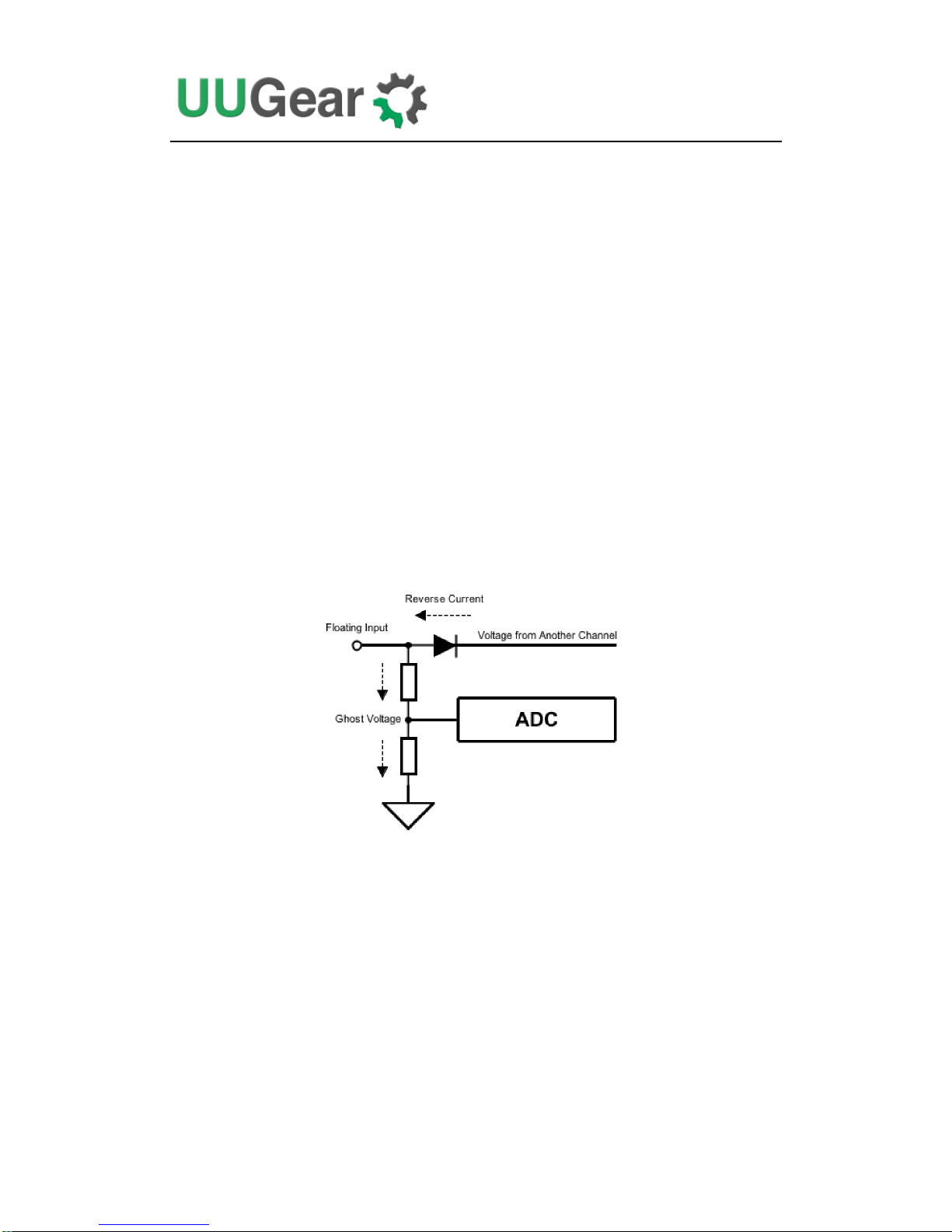
Ghost Voltage
If you leave any input channel floating (not connecting to any power supply), you
may see it has voltage too (in Zero2Go Omini Console). It is normal, because the
schottky diode for isolating each channel has a reverse leaking current, which could
be up to 0.5mA. That reverse current will generate a “ghost voltage” on the voltage
divider network, which the ADC (Analog to Digital Converter) on Zero2Go Omini
can detect.
Usually you don’t need to worry about it, and the ghost voltage only gets displayed
and will not bring any harm.
If you don’t want to see the ghost voltage, you may short the floating input to ground,
or remove the schottky diode, given that channel will never be used.
15
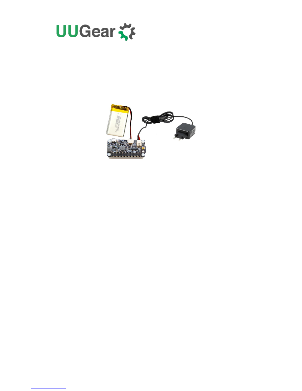
Work as Uninterruptible Power Supply (UPS)
Zero2Go Omini can be easily configured as an uninterruptible power supply (UPS)
for Raspberry Pi.
You will need at least two power supplies. For example, you connect a 3.7V Li-Po
battery pack and a 18V wall adapter to Zero2Go Omini.
Then you can make these configurations in Zero2Go Omini Console:
Set low voltage threshold to 3.2V
Set recovery voltage threshold to 4.2V
Set step-down engine always-on
Now your Zero2Go Omini becomes a UPS with strategies below:
1. If electric power supply is normal, the 18V from wall adapter will be used
2. When electric power supply fails, the 3.7V Li-Po battery pack will be used
3. When the voltage of battery goes below 3.2V, shutdown Raspberry Pi.
4. When the battery is fully charged (back to 4.2V), restarts Raspberry Pi.
5. When the power failure is recovered, uses the 18V from wall adapter.
Hardware Hackings
Zero2Go Omini’s hardware is quite hack-able. However, please understand that once
you make any hacking on your Zero2Go Omini, you will lose the warranty. So
please think twice before going further.
1. Interface with different Power Supplies
There are 3 input channels on Zero2Go Omini, and each of them has different
interface. Channel A uses a micro USB connector; Channel B uses an XH2.54-2P

16
connector; Channel C uses a universal wire connector and can connect DuPont wires
or any power wire.
If your power supply has different interface, for example, a barrel shaped plug, you
can prepare a barrel jack with two leads, and solder its leads to the pads on Zero2Go
Omini’s bottom surface.
You can solder the two leads on any channel (they all support 3.5~28V input):
The same idea can be used to interface any kind of power supply.

17
2. Change the Pin Used by Zero2Go Omini
Zero2Go Omini uses GPIO-4 (BCM naming) as SWITCH signal and GPIO-17 (BCM
naming) as System-Up signal. You can learn more details here.
The SWITCH signal is in HIGH state by default, and it goes LOW when you press
the button on Zero2Go Omini, then it goes back to HIGH when you release the
button. The System-Up signal is in LOW state by default, and it goes HIGH for 0.5
second after booting your Raspberry Pi.
You can change the pins used by Zero2Go Omini. What you need to do is to cut the
thin copper track on the back and wire the signal pad to new pin accordingly.
For example, if you want to use GPIO-27 (BCM naming) as SWITCH signal, you cut
the copper track between Switch and GPIO-4, and then wire the “Switch” pad to
GPIO-27, as shown in picture below:
You will also need to modify the daemon.sh file to adapt this change. Just change the
“HALT_PIN” variable to 27:
You can also change the pin used for System-Up signal as well. Just cut the copper
track between System-Up and GPIO-17, and then wire the System-Up pad to the new
pin. You will also need to change the “SYSUP_PIN” variable in daemon.sh file.
7 # halt by GPIO-4 GPIO-27 (BCM naming)
8 readonly HALT_PIN=4 HALT_PIN=27
9
10 # pull up GPIO-17 (BCM naming) to indicate system is up
11 readonly SYSUP_PIN =17
18
3. Modify and Upload Firmware
Usually you don’t need to modify the firmware, and we do not suggest to modify the
firmware, because it could damage the hardware if you don’t do it right. Just like
doing other hackings, once you upload the firmware by yourself, you will lose the
warranty. If you still want to proceed, please make sure you understand how it
works.
Zero2Go Omini uses an ATtiny841 microcontroller to control the DC-DC converter
engines, measure voltages and communicate with Raspberry Pi via I2C interface. The
firmware is developed with Arduino IDE and the source code can be found in GitHub
repository.
The firmware uses these open sourced libraries, and you will need to install them to
your Arduino IDE to have the firmware compiled properly:
ATTinyCore: https://github.com/SpenceKonde/ATTinyCore
analogComp: https://github.com/leomil72/analogComp
Please read the document of these libraries to learn how to install and configure them.
Before making any modification on firmware, please read its source code carefully
and fully understand it. Incorrectly modifying the firmware can lead to very bad
consequence. For example, if your firmware turns on the DC/DC step-up engine
when input voltage is 12V, that high voltage will reach your Raspberry Pi and
blow everything!
Although we are not obliged to support your modification on the firmware, we don’t
want you to kill your Zero2Go Omini and Raspberry Pi either. So please do ask us if
you have anything not sure in the firmware, and we will try to help.
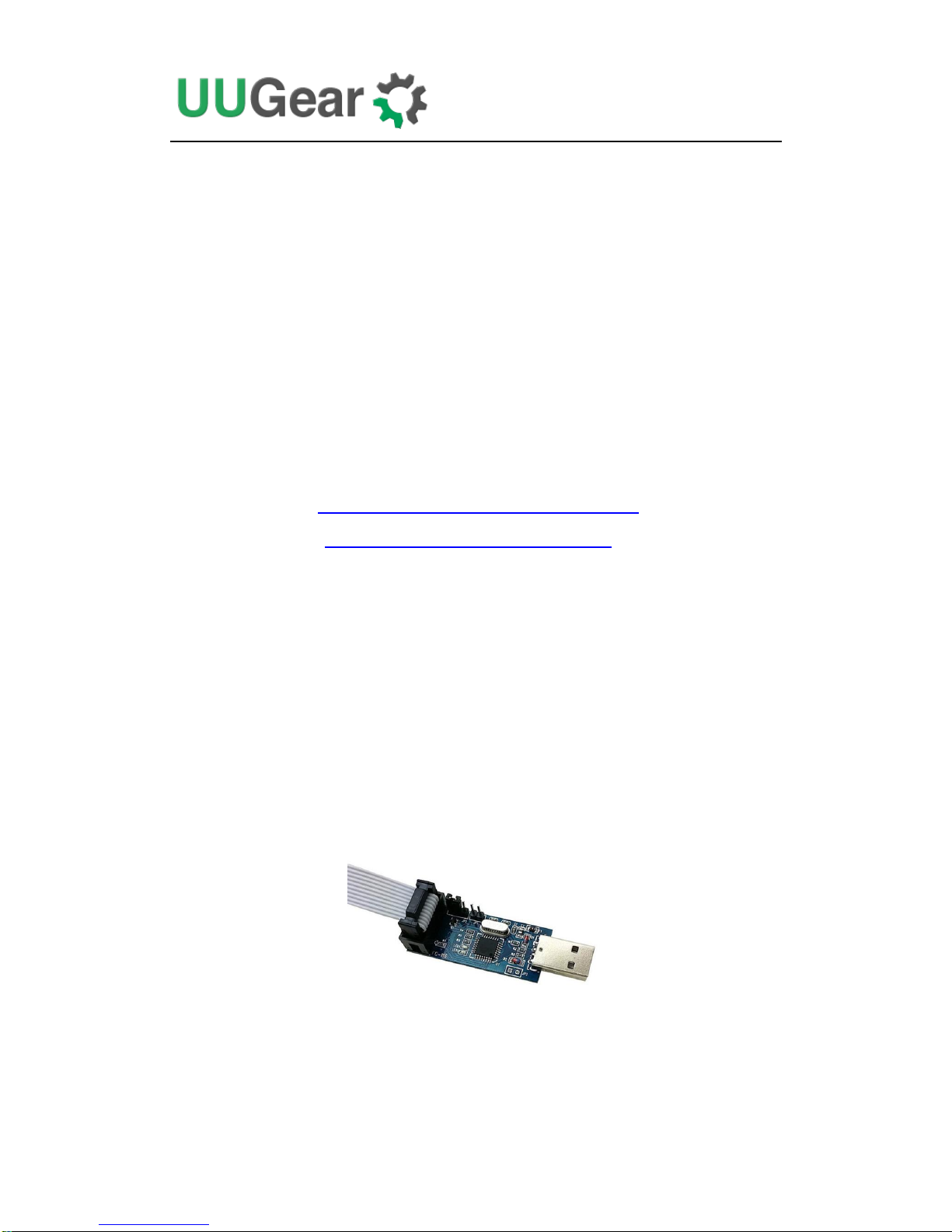
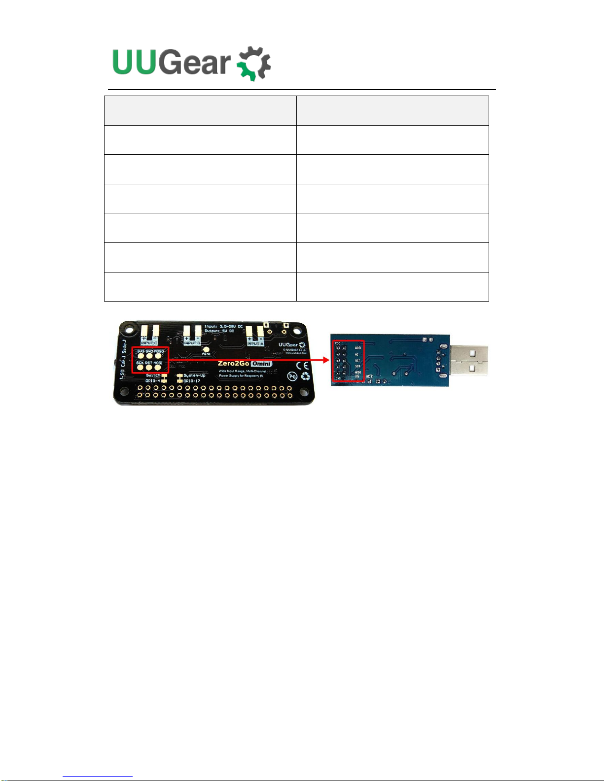
Assume you modify the firmware in your PC, then you will need a USB programmer
to upload the firmware to your Zero2Go Omini. Here we use USBasp as an example.
The USB programmer can communicate with Zero2Go Omini board via Serial
Peripheral Interface (SPI). You will need to wire the pads (pins) with same name
together:
19
Zero2Go Omini
USB Programmer
3V3
VCC
GND
GND
MOSI
MOSI
MOSO
MOSO
SCK
SCK
RST
RST
After doing so, you need to configure the programmer in your Arduino IDE. If you
are using USBasp, just select menu “Tools->Programmer->USBasp (ATTinyCore)”.
Now you can upload the firmware.
We strongly suggest to test the new firmware without having Raspberry Pi connected.
You can measure the output voltage with voltmeter, and make sure your Raspberry Pi
will not receive high voltage.
Zero2Go Omini Log Files
In the directory that you install your Zero2Go software, you can find on log files:
zero2go.log. If you need our help for solving a problem, please kindly put the log
files in email attachment too. This will help us to help you better.
The “zero2go.log” file records the history of all Zero2Go activities. If you think your
Zero2Go doesn’t behave right, this log file might provide more information for
debugging.

20
Frequently Asked Questions (FAQ)
1. What I2C Address is Used by Zero2Go Omini?
Raspberry Pi communicates with the MCU (ATtiny841) on Zero2Go Omini via I2C
protocol. The default I2C address is 0x29.
If you have Zero2Go Omini connected to Raspberry Pi and run “i2cdetect -y 1” in the
command line terminal, you will see the used address:
2. What I2C Registers Are Provided by Zero2Go Omini?
The MCU in Zero2Go Omini works as an I2C slave and Raspberry Pi can read/write
some registers via I2C interface. The software configures Zero2Go Omini by setting
the I2C register accordingly.
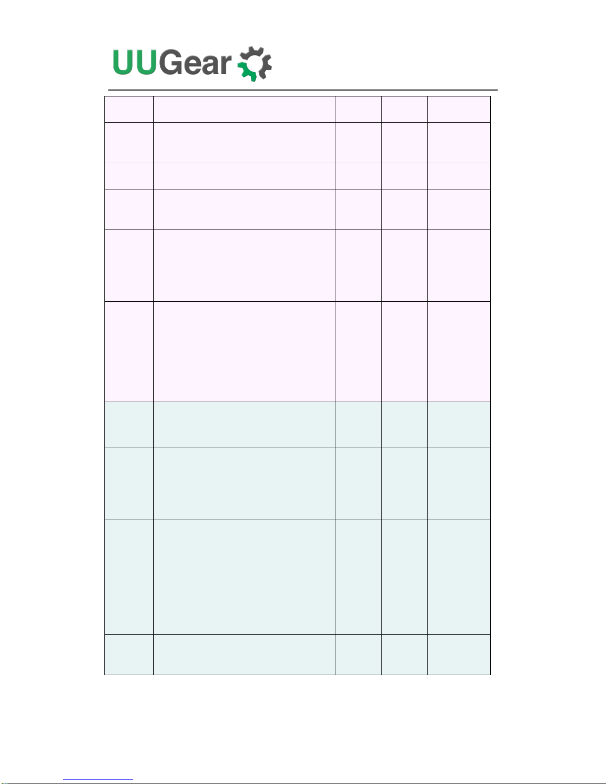
The table below shows the 16 registers provided by Zero2Go Omini. As you can see,
some of them are read-only (only get updated by firmware):
Address
Description
Range
Default
Accessible
0
Firmware ID
--
0x70
Read-only
1
Integer part for voltage of channel A
0~255
0
Read-only
2
Decimal part (multiple 100 times) for
voltage of channel A
0~99
0
Read-only
pi@raspberrypi ~ $
i2cdetect -y 1
0 1 2 3 4 5 6 7 8 9 a b c d e f
00: -- -- -- -- -- -- -- -- -- -- -- -- --
10: -- -- -- -- -- -- -- -- -- -- -- -- -- -- -- --
20: -- -- -- -- -- -- -- -- -- 29 -- -- -- -- -- --
30: -- -- -- -- -- -- -- -- -- -- -- -- -- -- -- --
40: -- -- -- -- -- -- -- -- -- -- -- -- -- -- -- --
50: -- -- -- -- -- -- -- -- -- -- -- -- -- -- -- --
60: -- -- -- -- -- -- -- -- -- -- -- -- -- -- -- --
70: -- -- -- -- -- -- -- --
pi@raspberrypi ~ $
21
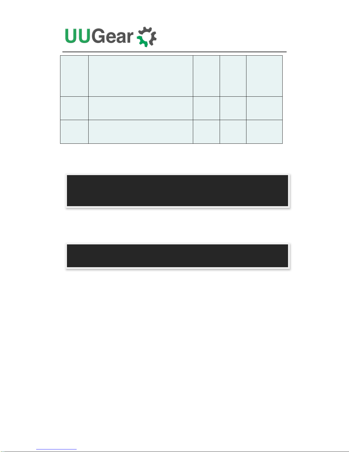
3
Integer part for voltage of channel B
0~255
0
Read-only
4
Decimal part (multiple 100 times) for
voltage of channel B
0~99
0
Read-only
5
Integer part for voltage of channel C
0~255
0
Read-only
6
Decimal part (multiple 100 times) for
voltage of channel C
0~99
0
Read-only
7
Working mode:
bulk (step-down) = 1
boost (step-up) = 0
1 or 0
1
Read-only
8
A flag indicates that whether the
previous shutdown is because of low
voltage:
Yes = 1
No = 0
1 or 0
0
Read-only
9
I2C slave address: default=0x29
0x08
~0x77
0x29
Read &
Write
10
State when power connected:
Default On = 1
Default Off = 0
1 or 0
0
Read &
Write
11
Red LED Blink interval:
1 second = 6
2 seconds = 7
4 seconds = 8
8 seconds = 9
6,7,8 or
9
8
Read &
Write
12
Low voltage threshold (multiple 10
times, 255=disabled)
0~255
255
Read &
Write
22
13
Set bulk converter always-on:
Yes = 1
No = 0
1 or 0
0
Read &
Write
14
The delay (multiple 10) before power
cut: default=50 (5 seconds)
0~255
50
Read &
Write
15
Recovery voltage threshold (multiple
10 times, 255=disabled)
0~255
255
Read &
Write
Below is an example to read the register at address 7, to know the current working
mode (0x00 means boost/step-up mode):
And below is an example to write the register at address 11, to set the blinking
interval to 1 second (using value 6):
Remarks: although the register at address 9 is writable, changing the I2C slave
address is more than writing an I2C register. You will need to modify the software
accordingly (change the I2C_SLAVE_ADDRESS value in utilities.sh file), and
reconnect the power supply to make it work.
pi@raspberrypi ~ $ i2cget -y 1 0x29 7
0x00
pi@raspberrypi ~ $
pi@raspberrypi ~ $ i2cset -y 1 0x29 11 6
pi@raspberrypi ~ $

23
3. What GPIO Pins Are Used by Zero2Go Omini?
The GPIO pins used by Zero2Go Omini are marked with green color in the table
below.
GPIO
(BCM)
Name
Physical
Name
GPIO
(BCM)
3.3V
1
2
5V 2
SDA 1
3
4
5V 3
SCL 1
5
6
GND
4 GPIO 7
7
8
TXD
14 GND
9
10
RXD
15
17
GPIO 0
11
12
GPIO 1
18
27
GPIO 2
13
14
GND
22
GPIO 3
15
16
GPIO 4
23 3.3V
17
18
GPIO 5
24
10
MOSI
19
20
GND
9 MISO
21
22
GPIO 6
25
11
SCLK
23
24
CE0 8
GND
25
26
CE1
7 0 SDA 0
27
28
SCL 0
1
5
GPIO 21
29
30
GND
6 GPIO 22
31
32
GPIO 26
12
13
GPIO 23
33
34
GND
19
GPIO 24
35
36
GPIO 27
16
26
GPIO 25
37
38
GPIO 28
20 GND
39
40
GPIO 29
21
As you can see in the table, Zero2Go Omini uses GPIO-4, GPIO-17, GPIO-2 (SDA
1) and GPIO-3 (SCL 1).

24
GPIO-4 is used as SWITCH signal. It goes LOW when you press the button on
Zero2Go Omini, then it goes back to HIGH when you release the button.
GPIO-17 is used as System-Up signal. It is in LOW state by default, and it goes
HIGH for 0.5 second when your Raspberry Pi finishes booting.
If you want Zero2Go Omini to use different pins, please read Change the Pin Used by
Zero2Go Omini to learn more.
GPIO-2 and GPIO-3 are for I2C communication between Raspberry Pi and the MCU
in Zero2Go Omini (ATtiny841). Multiple I2C devices can share these two pins, as
long as they have different I2C address.
Zero2Go Omini doesn’t actually use the TXD pin (it only monitors it). Using serial
port for data exchanging will not be a problem.
4. Is Zero2Go Omini Compatible with “Other Hardware”?
Please understand that we might not have the hardware you have on hand, and even if
we have, it is difficult for us to make tests on all these hardware with Zero2Go Omini.
Fortunately, it is not that difficult to figure out the answer by yourself. Basically you
just need to consider the I2C address and GPIO pins used by the “Other Hardware”.
If the “Other Hardware” doesn’t use any GPIO pin that used by Zero2Go Omini, and
it doesn’t use 0x29 I2C address, then it should be compatible with Zero2Go Omini.
If the “Other Hardware” uses 0x29 I
2
C address, it will be a confliction with Zero2Go
Omini. You can either change the I
2
C address used by the “Other Hardware” (if
possible), or change the I2C address used by Zero2Go Omini (learn more here).
If you have no idea which I2C address (if applicable) or GPIO pins are used by the
“Other Hardware”, please contact its developer, as they certainly know their hardware
and can provide you accurate information about it.
5. How to Understand the Color of LED on Zero2Go Omini?
There is an RGB three-color LED on Zero2Go Omini, and it indicates the current
working status of the board. The RGB LED actually include 3 standalone LEDs. They
have red, green and blue color and each of them can be turned on/off.
When Zero2Go is standing by, it blinks the LED in red with an interval. Telling you
that the power supply has connected, and you can tap the button to turn on your
Raspberry Pi.

25
If one of the input channel has voltage higher than 5.5V, Zero2Go Omini uses the
step-down engine to output 5V, and the LED will be turned on in green, indicating
Zero2Go is working in bulk (step-down) mode.
= Bulk (step-down) Mode
If all input channels have voltage lower than 5.5V, Zero2Go uses step-up engine to
output 5V or the input voltage, whoever is higher. In this case the LED will be turned
on in blue, indicating Zero2Go is working in boost (step-up) mode.
= Boost (step-up) Mode
If you have configured step-down engine always-on. When Zero2Go is working in
boost (step-up) mode, you will see the LED in cyan instead, because its internal blue
and green LEDs are both on.
= Step-Up Mode + Step-Down Engine Always-On
After your Raspberry Pi is booted, the internal red LED will be on for 0.5 second and
you will see a flash in yellow (when working in step-down mode), or in purple (when
working in step-up mode), or in white (when working in step-up mode with
step-down engine always-on).
= Step-Down Mode
= Step-Up Mode
= Step-Up Mode with Step-Down Engine Always-On
If you tap the button on Zero2Go Omini to turn off your Raspberry Pi, the internal red
LED will also be on before the system shutdown. You will see the LED in yellow, in
purple or in white, for the same reason above.

26
Revision History
Revision
Date
Description
1.00
2018.08.28
Initial revision
1.01
2018.09.09
Fix some typos
 Loading...