


Copyright © 2017 UUGear s.r.o. All rights reserved.
Zero2Go
Wide Input Range Power Supply for Your Raspberry Pi
User Manual (revision 1.02)

Copyright © 2017 UUGear s.r.o. All rights reserved.
Table of Content
Product Overview ............................................................................................... 1
Product Details ................................................................................................... 3
Package Content ................................................................................................ 4
Specifications ..................................................................................................... 5
Mounting on Raspberry Pi Zero .......................................................................... 6
Mounting on Other Raspberry Pi Models ............................................................ 8
Connect Power Source .................................................................................... 10
Working Modes ................................................................................................ 12
Before Installing Software ................................................................................ 13
Software Installation ......................................................................................... 14
GPIO Pins Used by Zero2Go ........................................................................... 15
About the Protective Frame .............................................................................. 16
Revision History ............................................................................................... 17

1
Product Overview
Zero2Go is a small and smart power supply add-on for Raspberry Pi. When using the
pogo pin connector (included in package), it can connect to Raspberry Pi Zero without
soldering. It also supports other Raspberry Pi models who have 40-pin header.
Main features include:
Same board size with Raspberry Pi Zero
No soldering required when mounting on Raspberry Pi Zero
Wide range input voltage (5~26V)
Reversed polarity protection
Connect power source via micro-USB, DC power plug or electric wires
Support “pass-through” and “step-down” modes (auto switching)
Single tap to startup/shutdown Raspberry Pi
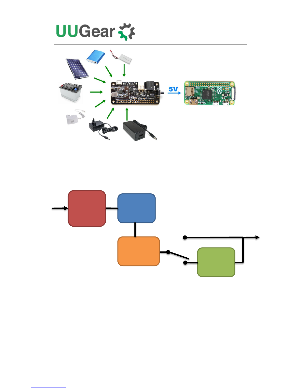
Zero2Go has quite wide input range (5V~26V), so it is will be convenient to power
your Raspberry Pi with power bank, Li-Po battery pack, solar panel, car battery or
different kinds of power adapters etc.
2
The board size of Zero2Go is exactly the same with Raspberry Pi Zero, and can be
mounted on Raspberry Pi Zero without soldering (thanks to the pogo pin connector).
You can also mount Zero2Go on other Raspberry Pi models that have 40-pin header,
if you solder a female header on Zero2Go as well (not included in the package).
How Zero2Go works? The diagram below gives you the main idea.
If the input voltage is higher than 5.5V, then the DC-DC converter will be used,
otherwise the input voltage will pass through to output. The e-Latching Switch will
maintain the power if system is up and the button on Zero2Go is not tapped or hold.
Since DC-DC converter needs more dropout to work well, inputting 5.5~7.0V should
be avoided when possible.
DC-DC
Step Down
Reversed
Polarity
Protection
e-Latching
Switch
Voltage
Comparator
Pass-through
Output
5V
Input
5~26V

3
Product Details
The figure below shows how Zero2Go looks like:
1) Micro-USB port for power source connection.
2) Red LED as error indicator.
3) Green LED as DC-DC step down indicator.
4) Blue LED as 5V pass through indicator.
5) Terminal block for power source connection.
6) DC power jack for power source connection.
7) Tact switch for power on/off.
8) 40-pin header footprint.
9) Acrylic protective frame.

4
Package Content
Each package of Zero2Go contains:
Zero2Go board x 1
Plastic male-female standoff x 4
M2.5 x 4 mm screws x 4
M2.5 nuts x 4
Dual-head Pogo pin connector (5-pin set)

5
Specifications
Dimension:
65mm x 30mm x 9mm
Weight
10g (net weight without any accessory)
Input Voltage (Vin)
5~26V 1
Output Voltage (V
out
)
5V (5% tolerance)
Max Output Current
2.6A 2
DC-DC Efficiency
88% max
LED Indicators
Red: lights up when input polarity is reversed
Green: lights up when DC-DC converter is working
Blue: lights up when input pass through to output
Static Current
~0.5mA when Vin=5V
~4mA when Vin=26V 3
1
Input 5.5~7.0V is not recommended as the DC-DC converter needs more
dropout to work well.
2
Without adding heat sink to DC-DC chip and the inductor (U2 and L1), we
suggest to keep the current below 1.5A for long term usage. If you are using
the Pogo pin connector to output all current to Raspberry Pi Zero and
peripherals, the current should be 1A or lower.
3
It is the current drawn from the power source, when Raspberry Pi doesn’t get
powered.

6
Mounting on Raspberry Pi Zero
To mount Zero2Go on Raspberry Pi Zero (without 40-pin header soldered), the first
step is to fix the 4 male-female standoffs on four corners with screws.
Then you place the pogo pin connector on the correct position. Please make sure the
small tip on the plastic frame is on the right and it points to the SD card, as shown
below:

7
Now you can mount Zero2Go above your Raspberry Pi Zero, please make sure the
pogo pin connector contacts the correct pads:
Use the 4 nuts to fix your Zero2Go at its place. You may find tweezers are quite
helpful in this case:
After tightening the 4 nuts, Zero2Go is now firmly mounted on your Raspberry Pi Zero.
Please notice the pogo pin connector is designed to work with 1A current, if you
are expecting a much higher current output, please consider soldering a 40-pin
header for the connection.

8
Mounting on Other Raspberry Pi Models
If you want to mount Zero2Go on other Raspberry Pi models, you will need to solder a
40-pin header (not included in package) on your Zero2Go.
Which type of header should you solder? It depends. If you intend to mount Zero2Go
on Raspberry Pi A+, B+, 2B or 3B, which has male 40-pin header onboard, you should
solder a female 40-pin header on Zero2Go. Optionally it could be a stacking header
which has extra long pins. Below is such an example:
If you are mounting Zero2Go on a Pi Zero with a female 40-pin header soldered, you
should solder a male 40-pin header on your Zero2Go. This is also the suggested
way for driving high current devices from Pi Zero.
After soldering the pin-header, mounting Zero2Go to your Raspberry Pi is the same
with mounting other HATs. Just connect the 40-pin headers together and it is done.
The pictures below shows how Zero2Go looks like when being mounted on Raspberry
Pi A+ and Raspberry Pi 3.

9
10
Connect Power Source
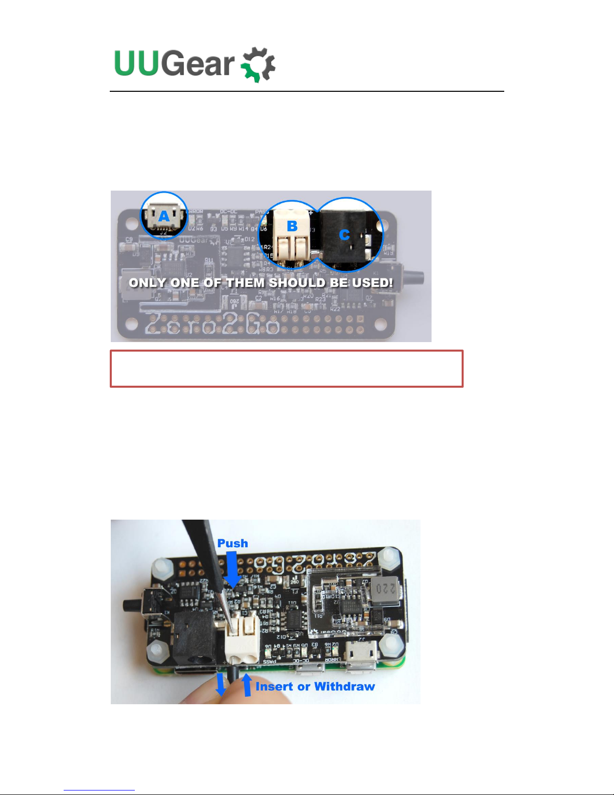
Zero2Go has three input power port on board, the micro-USB port (A), the terminal
block (B) and DC power jack (C). You can use one of them to connect the power
source for your Raspberry Pi.
The micro-USB port is for connecting those power adapters with matching plug. The
official Raspberry Pi power adapter, many mobile phone chargers and all power
banks belongs to this category. Although most devices that output 5V to micro-USB,
this micro-USB port can accept 5~26V.
The terminal block in white can connect metal wires with diameter 0.5~1mm. When
connecting or disconnecting a wire, you need to push the small button on top, and
then insert or withdraw the wire.
Caution: do not connect multiple power sources at the same time!
11
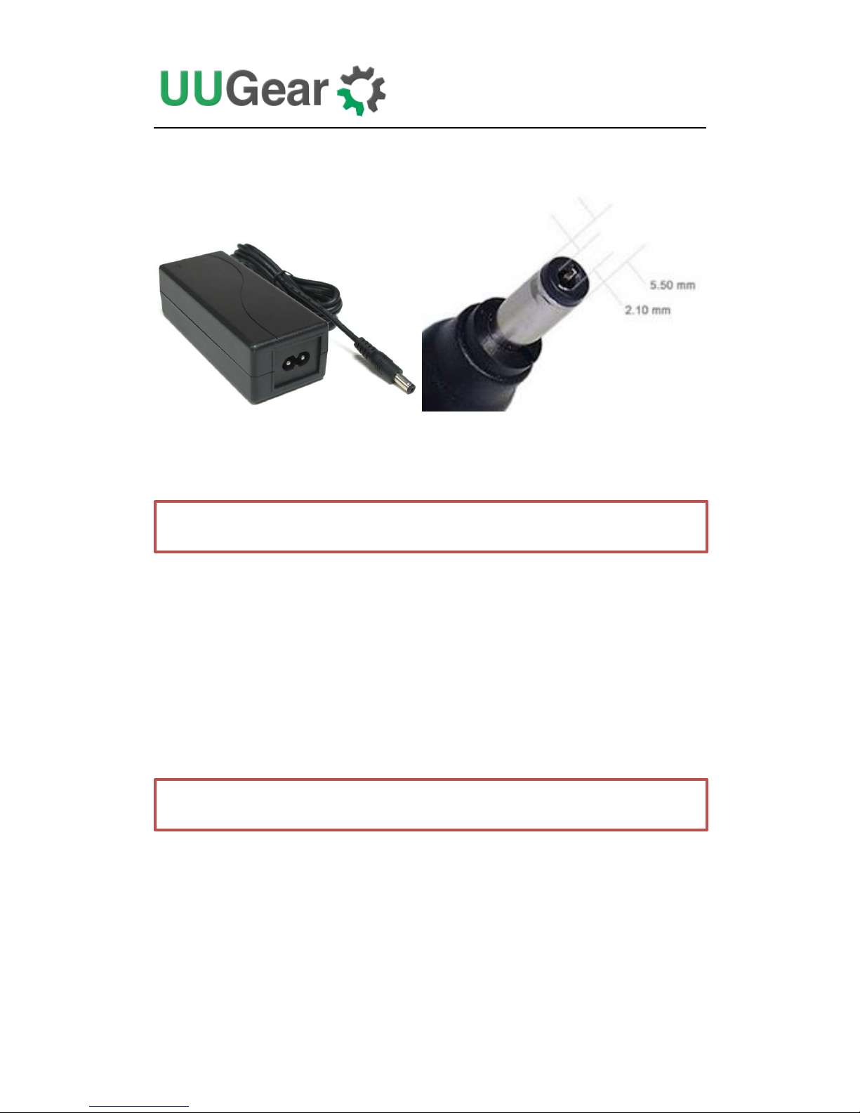
The DC power jack in black is for connecting those power adapters with
5.5mm/2.1mm plug. Many power adapters for notebook belongs to this category.
Different than the micro-USB and then terminal block, the connection between barrel
shaped plug and DC power jack is not that tight, as it could still be rotated after the
connection. This might lead to unstable input voltage, which should be avoided.
If Zero2Go is used on a portable project, it is recommended to use the micro-USB or
terminal block for power source connection. If the DC power jack is used, it is
recommended to take additional efforts to fix the barrel shaped plug on its place.
Please keep in mind that, the power source should have very solid connection to
Zero2Go. If you are using the terminal block, please make sure the wires are tightly
fixed, and they should not be disconnected during the usage. If the connection is not
reliable, it could lead to very bad consequence, especially when input voltage is
higher than 20V. In worse case it could burn out the MOSFET on Zero2Go and then
kill your Raspberry Pi!
Caution: please avoid poor contact between power source and Zero2Go.
Caution: quickly connect and disconnect power source is a big NO NO!!!

12
Working Modes
If the input polarity is reversed, the red LED will light up and Zero2Go does not work.
This will not harm any device as the power switch is disabled in this case.
After correctly connection with the power source, a single tap on the button (K1) will
turn on your Raspberry Pi.
If the input voltage is less than 5.5V, Zero2Go works in “pass-through” mode, and
the input voltage will be directly output (with very low voltage drop). In this case the
blue LED will light up.
If the input voltage is higher than 5.5V, Zero2Go works in “step-down” mode, and the
DC-DC converter will convert input voltage to 5V output. In this case the green LED
will light up.

13
Before Installing Software
You will need to installed the OS on the SD card first. We recommend NOT to use
NOOBS, instead download the Raspbian image and directly flash it into your SD card
(tutorial is here). The process could be faster and you will not have the problem
caused by the NOOBS boot menu (read on for details).
The software of Zero2Go has been tested under Raspbian Jessie. Raspbian
Wheezy should also work, but it is better to use Jessie as it will be much easier to
install Qt 5, which is required by the (optional) GUI of the software.
The software of Zero2Go might also work on other operating systems with or without
modification. The software is written in BASH, so it could be easily modified by the
customers to support other OS. However, at lest for now, only Raspbian Jessie and
Wheezy are officially tested. You should have mind preparation that tweaking might
be needed when using Zero2Go on other operating systems.
If you have installed the OS with NOOBS, please make sure to skip the boot
menu. Otherwise the boot menu will postpone the booting long enough to make
Zero2Go think the system is down and then cut the power (so your Raspberry Pi will
not boot).
Here is how to skip the NOOBS boot menu: you insert your SD card to your PC (use a
SD card reader if your PC doesn’t have SD card slot), open the RECOVERY partition
and create a text file named “autoboot.txt” there. Edit it and put this into the file:
boot_partition=6
It tells NOOBS to boot from the partition who is numbered 6. It is usually the case
when you installed only one OS on the SD card (more details could be found here). If
you have multiple OS installed, you can run “sudo fdisk –l” command to find the
partition to boot with.
Remarks: there is a regression on NOOBS V2.2 and V2.3, so the trick above will not
work on (at least) these two versions (details here). We hope it could be fixed soon,
meanwhile you can use NOOBS V2.1 to avoid this problem (download from here), or
even better, do not use NOOBS and directly flash the OS into the SD card.

14
Software Installation
After mounting Zero2Go on your Raspberry Pi, you can tap on the button to turn your
Raspberry Pi on. However, without installing the software, you can only hold the
button for several seconds to force the power cut, which is not recommended.
How the Zero2Go software works? The software will run in the background after boot,
and listen to your button input (via GPIO-4). It will initiate a shutdown command once
you tap on the button. After the system gets shutdown, the TXD pin will go LOW
permanently, and Zero2Go will then fully cut the power.
Zero2Go’s software is a subset of the software for Witty Pi. So if you have installed
Witty Pi’s software on your Raspberry Pi, you don’t need to install Zero2Go’s software
and it will work just out of the box.
To install Zero2Go’s software, please run this command in your home directory:
If your Raspberry Pi has internet connection, it will immediately download the script
from our website, and you will then see the “installZero2Go.sh” script in your home
directory. Then you just need to this script with with sudo:
Please notice that sudo is necessary to run this script. This script will copy a file to
“/etc/init.d/zero2go”, and register it to run after boot.
pi@raspberrypi ~ $ wget http://www.uugear.com/repo/Zero2Go/installZero2Go.sh
pi@raspberrypi ~ $ sudo sh installZero2Go.sh

15
GPIO Pins Used by Zero2Go
Besides the +5V and GND pins, Zero2Go uses GPIO-4 (BCM naming) to monitor the
button tapping. The TXD pin is also monitored but it will not affect the data transferring
via serial port. Zero2Go will cut power when TXD pin gets pulled down for long
enough (> 3 seconds).
GPIO
(BCM)
Name
Physical
Name
GPIO
(BCM)
3.3V
1
2
5V
2
SDA 1
3
4
5V 3
SCL 1
5
6
GND
4 GPIO 7
7
8
TXD
14 GND
9
10
RXD
15
17
GPIO 0
11
12
GPIO 1
18
27
GPIO 2
13
14
GND
22
GPIO 3
15
16
GPIO 4
23 3.3V
17
18
GPIO 5
24
10
MOSI
19
20
GND
9 MISO
21
22
GPIO 6
25
11
SCLK
23
24
CE0 8
GND
25
26
CE1
7 0 SDA 0
27
28
SCL 0
1 5 GPIO 21
29
30
GND
6 GPIO 22
31
32
GPIO 26
12
13
GPIO 23
33
34
GND
19
GPIO 24
35
36
GPIO 27
16
26
GPIO 25
37
38
GPIO 28
20 GND
39
40
GPIO 29
21
16
About the Protective Frame
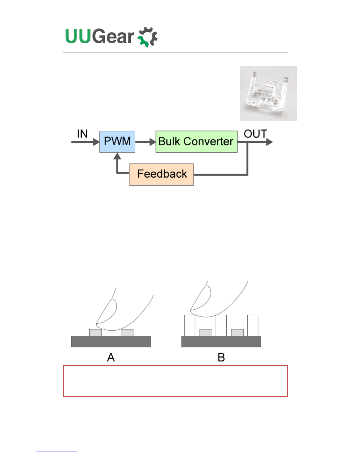
Around the DC-DC chip (U2), there is an Acrylic protective frame,
which sticks on the top surface of the PCB with adhesive gel.
What is this frame for? It is there to protect the DC-DC circuit,
from your finger. Below is a (very simplified) chart to show how the
DC-DC converter works.
The feedback channel is there to make sure the output voltage is at the expected level.
If for any reason, the feedback channel is interfered, the PWM module will collect
wrong sample and the output voltage will be wrong.
In Zero2Go we use a SO-8 IC (U2) to build the DC-DC converter, some resistors
and capacitors around setup the feedback channel for it. If you use a finger to
touch some of them at the same time, you may interfere the feedback channel and
the result could be disaster (scenario A in figure below). With the Acrylic protective
frame mounted, your figure will not be able to touch those components (scenario
B in figure below).
Caution: please try not to remove the Acrylic protective frame, if you are
using Zero2Go without a case.

17
Revision History
Revision
Date
Description
1.00
2016.11.22
Initial revision
1.01
2017.03.03
Add caution about unreliable power source connection.
1.02
2017.04.03
Add “Before Installing Software” section.
 Loading...