

Page 1

User Manual
WX Series WiFi Controller
Page 2

Copyright Notice
© 2000-2016, Shanghai UTT Technologies Co., Ltd.
All rights reserved.
The information of this publication is protected by copyright. No part of this publication may be
reproduced, transmitted, transcribed, stored in a retrieval system, or translated into any language
without written permission from the copyright holders. The scope of delivery and other details are
subject to change without prior notice.
Trademark
UTT® is a registered trademark of Shanghai UTT Technologies Co., Ltd.
Other trademarks and registered trademarks of products mentioned in this publication may be the
properties of their respective owners and are only used for identification purposes.
Version 1.0_201603
Page 3

Table of Contents
About this Manual ............................................................................................................................. 1
0.1 Manual Description .......................................................................................................... 1
0.2 Web UI Style .................................................................................................................... 1
0.3 Document Conventions ................................................................................................... 2
0.3.1 Format ................................................................................................................... 2
0.3.2 Icons ...................................................................................................................... 2
0.4 Factory Default Settings .................................................................................................. 2
0.5 Contact us ........................................................................................................................ 3
Chapter 1. Hardware Installation ................................................................................................... 4
1.1 Panel Description ............................................................................................................ 4
1.2 Installation Guideline ....................................................................................................... 5
1.3 Installation Requirements ................................................................................................ 5
1.4 Installation Procedure ...................................................................................................... 6
1.5 Connecting the Device .................................................................................................... 7
Chapter 2. Logging to the Device .................................................................................................. 8
2.1 Configuring Your Computer ............................................................................................ 8
2.2 Logging to the Device .................................................................................................... 10
Chapter 3. Map Tab ..................................................................................................................... 13
3.1 Overview ........................................................................................................................ 14
3.2 Details ............................................................................................................................ 14
3.3 Load ............................................................................................................................... 15
3.4 Interference .................................................................................................................... 16
3.5 Coverage ....................................................................................................................... 17
3.6 Map ................................................................................................................................ 20
Page 4

Chapter 4. Statistics Tab .............................................................................................................. 22
Chapter 5. Access Point Tab ....................................................................................................... 25
5.1 AP Controller ................................................................................................................. 25
5.1.1 Terminology ........................................................................................................ 25
5.1.2 Working Principle ................................................................................................ 26
5.1.3 Layer 2 Roaming ................................................................................................. 27
5.2 AP Settings .................................................................................................................... 28
5.2.1 Batch settings ...................................................................................................... 29
5.2.2 Single AP Settings .............................................................................................. 30
Chapter 6. Users Tab ................................................................................................................... 38
6.1 Connected ..................................................................................................................... 38
6.2 Disconnected ................................................................................................................. 39
6.3 Blacklist .......................................................................................................................... 39
Chapter 7. Events Tab ................................................................................................................. 40
Chapter 8. Settings Tab ............................................................................................................... 43
8.1 WLAN............................................................................................................................. 43
8.1.1 RF ........................................................................................................................ 44
8.1.2 VLAN ................................................................................................................... 46
8.1.3 Security ............................................................................................................... 47
8.1.4 QoS ..................................................................................................................... 52
8.2 RF .................................................................................................................................. 52
8.3 Load Balance ................................................................................................................. 55
8.4 Firmware ........................................................................................................................ 56
8.5 Example of AP centralized management ...................................................................... 56
8.6 Example of AP centralized management (Three layer management) ......................... 59
Chapter 9. System Tab ................................................................................................................ 64
Page 5

9.1 Information ..................................................................................................................... 64
9.2 Admin ............................................................................................................................. 64
9.3 Time ............................................................................................................................... 66
9.4 System ........................................................................................................................... 67
Chapter 10. FAQ ......................................................................................................................... 70
Appendix A List of Common IP ....................................................................................................... 71
Appendix B Common service ports ................................................................................................ 72
Page 6
UTT Technologies About this Manual
http://www.uttglobal.com Page 1
About this Manual
Notes: For better user experience, it is strongly recommended to use Internet Explorer 10.0
or above, Google Chrome or Firefox.
0.1 Manual Description
This manual applies to UTT WX Series WiFi Controller.
The manual describes the characteristics and features of UTT WX Series WiFi Controller, which
are based on ReOS_SE V2.8.0 firmware. It mainly describes how to configure and manage the
Device via Web UI. Please make sure that your Device’s firmware version accords with ReOS_SE
V2.8.0. As the product or firmware upgrades or other changes happen, this guide will be updated
periodically.
In addition, as the product specifications of each model may differ, please contact UTT support
team for more information if needed.
Note:
The Device (first letter in uppercase.) mentioned in this manual stands for WX Series WiFi
Controller.
0.2 Web UI Style
The Device’s Web User Interface (Web UI) follows the web standards, as follows:
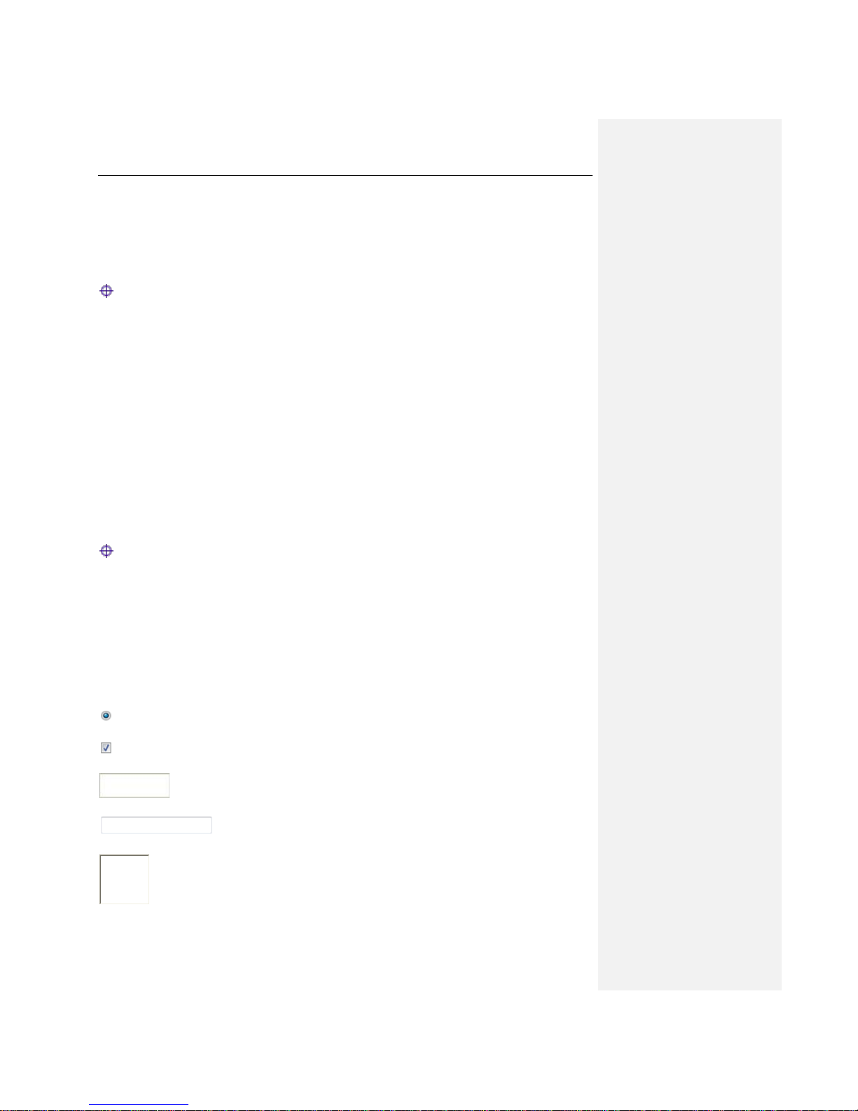
Radio Button: Allows you to choose only one of a predefined set of options.
Check Box: Allows you to choose one or more options.
Button: Allows you to click to perform an action.
Text Box: Allows you to enter text information.
List Box: Allows you to select one or more items from a static multiple line text box.
Page 7
UTT Technologies About this Manual
http://www.uttglobal.com Page 2
Drop-down List: Allows you to choose one item from a list. When a drop-down
list is inactive, it displays a single item. When activated, it drops down a list of items, from which
you may select one.
0.3 Document Conventions
0.3.1 Format
Notes: Please pay attention to the content of notes.
Parameters: Describe the meaning of basic parameters or buttons. If there is “*” before that
parameter, it couldn’t be empty.
Bullets: List the parallel content.
Bold font: Examples of information displayed on the screen.
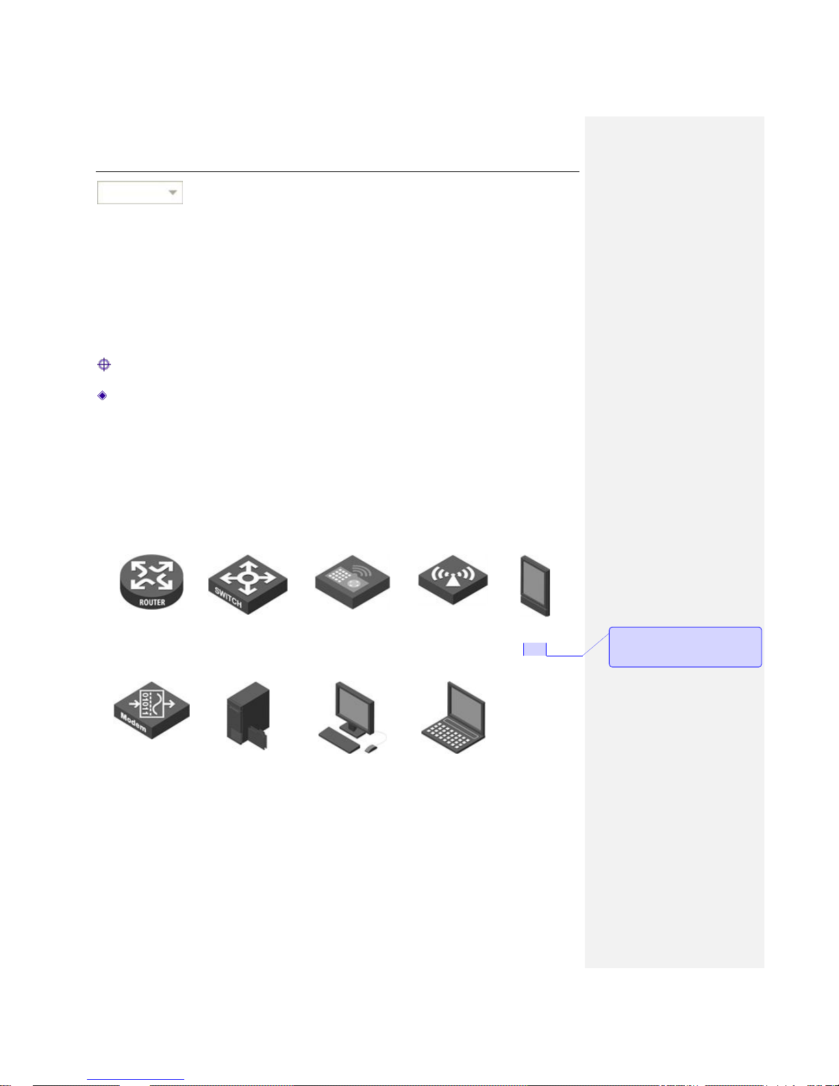
0.3.2 Icons
Router
Switch
Access Controller
Access Point
PDA
Modem
Server
Wired client
Wireless client
0.4 Factory Default Settings
The factory default settings of interfaces are shown in the following table.
批注 [周瑶1]: PDA 现在用的很少吧,
需不需要删除或者换掉,整篇文档里
没有见到试用该图标
Page 8
UTT Technologies About this Manual
http://www.uttglobal.com Page 3
Parameter
Default Value
Description
User Name
admin
Both the User Name and
Password are case sensitive.
Password
admin
LAN IP Address
192.168.1.253/255.255.255.0
You can use this IP address to
access the Device through a Web
browser.
Table 0- 1 Factory Default Settings of Interfaces
0.5 Contact us
If you have any question about the installation or using the Device, please contact us as the
following ways:
Phone: +86 21-67766519, 67766527
Global Sales Office Number: +1(626)722-5032
Email: [email protected]
批注 [周瑶2]: 请确认 Contact 信息
Page 9
UTT Technologies Hardware Installation
http://www.uttglobal.com Page 4
Chapter 1. Hardware Installation
This chapter describes the physical characteristics of the WX Series WiFi Controllers and explains how
to install them.
1.1 Panel Description
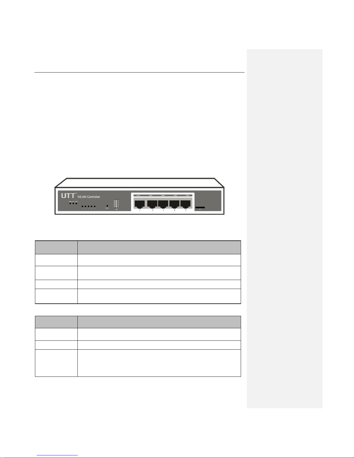
The LEDs and network ports are located on the front panel of the Device, here we use WX-1000S as
an example, as for other models, please see the actual product.
Figure 1-1 Front Panel -- WX-1000S
LED
Description
PWR
The Power LED indicator is on when the Device is powered on.
SYS
The LED indicator blinks twice per second when the system is operating
properly, and it will blink slower under heavy load.
USB
The LED indicator is on when the USB interface is connected properly.
Link/Act
When a device is connected to a port properly, the port’s corresponding LED
indicator will be on. The indicator will blink when there’s traffic on that port.
Table 1-1 LEDs Description
Interface/Button
Description
LAN port
These interfaces provide a LAN connection to network devices, such as PCs
or switches.
USB port
Plug in a USB storage for data sharing.
Reset
Reset current settings to the factory default settings. When the Device is
powered on, use a pin or paperclip to press and hold the Reset button for
more than 5 seconds, and then release the button. After that, the Device will
restart with factory default settings.
Page 10
UTT Technologies Hardware Installation
http://www.uttglobal.com Page 5
Note: The reset operation will clear all the configuration that you have made.
Table 1-2 Interfaces and Buttons Description
1.2 Installation Guideline
When determining where to place the Device, please observe these guidelines:
Make sure that your workbench or standard rack is level and stable.
Do not place heavy objects on the Device.
Make sure that there is proper space for heat dissipation and adequate ventilation around the
Device.
Position the Device out of direct sunlight and away from sources of heat and ignition.
Please install the Device in a place far away from any High Power Radio or Radar Station.
Keep the Device far away from water!
Please use the supplied power cord.
1.3 Installation Requirements
The following items are required for installation:
1) Broadband Internet connection.
2) Tools and equipment:
(1) Broadband modem (optional).
(2) PC with an Ethernet card and TCP/IP installed.
(3) Network devices like a hub, a switch, a wireless access point.
(4) Network cables.
(5) Screwdriver.
(6) Power outlet.
Page 11
UTT Technologies Hardware Installation
http://www.uttglobal.com Page 6
1.4 Installation Procedure
Before you install the Device, make sure your Internet connection is working properly. If it is not,
please contact your ISP.
1) Installing the Device on a Flat Surface
(1) Make sure the Device is powered off.
(2) Place the Device upside down on a sturdy, flat bench with a power outlet nearby. Make sure
that the bench is well grounded.
(3) Remove the adhesive backing from the supplied rubber feet. Attach the four rubber feet to
the round recessed areas on the bottom of the Device.
(4) Turn the Device over to make it right side up on the bench.
2) Installing the Device in a 19-inch Standard Rack
Follow these steps to install the Device in a 19-inch standard rack:
(1) Make sure the Device is powered off.
(2) Make sure the rack is stable and well grounded.
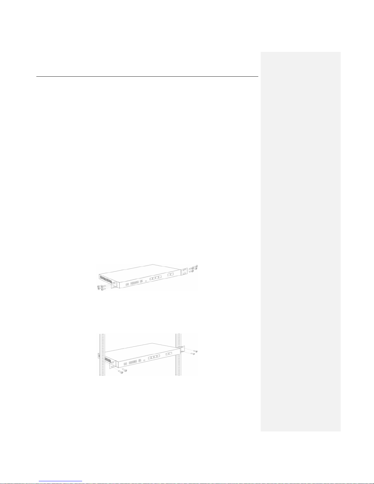
(3) Attach the supplied rack-mount brackets to the left and right side of the Device with the
supplied screws, and secure the brackets tightly, as shown below.
Figure 1-2 Attaching Brackets to the Device
(4) Insert the Device into the rack, and align the brackets to the rack.
(5) Use the supplied screws to secure the Device in the rack.
Figure 1-3 Mounting the Device in a Rack
Page 12
UTT Technologies Hardware Installation
http://www.uttglobal.com Page 7
1.5 Connecting the Device
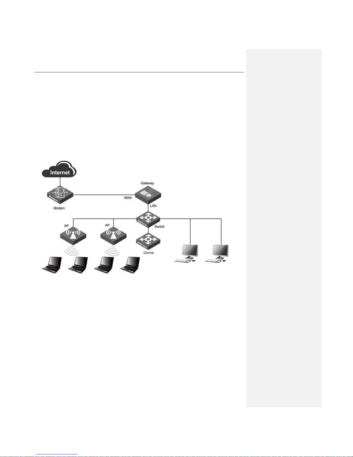
Follow these steps to connect the Device:
1)Connect the Device to the local network
Connect one end of an Ethernet cable to one of the LAN ports on the Device, and the other end to a
network port on a PC, hub, switch or wireless access point.
2)Power on the Device
Before you power on the Device, make sure that the power supply is normal and well grounded.
Figure 1-4 Connecting the Device
Page 13

UTT Technologies Logging to the Device
http://www.uttglobal.com Page 8
Chapter 2. Logging to the Device
This chapter describes how to configure TCP/IP settings on your computer, and how to login to the
Device. In addition, it briefly describes the layout of the Device’s Web interface.
2.1 Configuring Your Computer
To configure the Device via Web UI, you need to properly configure TCP/IP settings on the computer
that you use to manage the Device. To achieve this, follow below steps:
Step 1 Connect the computer to a LAN port of the Device.
Step 2 Install TCP/IP protocol on your computer. If it is already installed, please skip this step.
Step 3 Do one the following step to configure TCP/IP settings on your computer:
(1) If you want to set the IP address and other settings manually, select Use the
following IP address, set the IP address to an unused one in the 192.168.1.0/24
subnet, subnet mask to 255.255.255.0, and default gateway to 192.168.1.1. Note:
the Device’s default LAN IP address is 192.168.1.252 with a subnet mask of
255.255.255.0.
(2) If a DHCP server is available on your network, and you want IP settings to be
assigned automatically, select Obtain an IP address automatically and Obtain
DNS server address automatically.
Step 4 Use the Ping command to verify network connectivity between the computer and the
Device. Open the command line interface on the computer, type ping 192.168.1.252, and
then press Enter.
A successful ping will look like this.
Page 14

UTT Technologies Logging to the Device
http://www.uttglobal.com Page 9
An unsuccessful ping will look like this.
If the Ping command is successful, the connection between the computer and the Device is working
properly. If the Ping command fails, please follow these steps:
Pinging 192.168.1.252 with 32 bytes of data:
Request timed out.
Request timed out.
Request timed out.
Request timed out.
Ping statistics for 192.168.1.252:
Packets: Sent = 4, Received = 0, Lost = 4 (100% loss),
Approximate round trip times in milli-seconds:
Minimum = 0ms, Maximum = 0ms, Average = 0ms
Pinging 192.168.1.252 with 32 bytes of data:
Reply from 192.168.1.252: bytes=32 time<1ms TTL=255
Reply from 192.168.1.252: bytes=32 time<1ms TTL=255
Reply from 192.168.1.252: bytes=32 time<1ms TTL=255
Reply from 192.168.1.252: bytes=32 time<1ms TTL=255
Ping statistics for 192.168.1.252:
Packets: Sent = 4, Received = 4, Lost = 0 (0% loss),
Approximate round trip times in milli-seconds:
Minimum = 0ms, Maximum = 0ms, Average = 0ms
Page 15
UTT Technologies Logging to the Device
http://www.uttglobal.com Page 10
1) Check physical connection: Make sure that the LAN LED on the Device and the LED on your
computer’s network card are lit.
2) Check TCP/IP settings: Make sure that your computer is on the same subnet as the Device’s
LAN interface. E.g., if the Device’s LAN IP address is 192.168.1.252 (default), the computer’s IP
address must be an unused IP address in the 192.168.1.0/24 subnet.
2.2 Logging to the Device
No matter what operating system is installed on your computer, such as, MS Windows, Macintosh,
UNIX, or Linux, and so on, you can configure the Device through the Web browser (e.g., Internet
Explorer, Firefox).
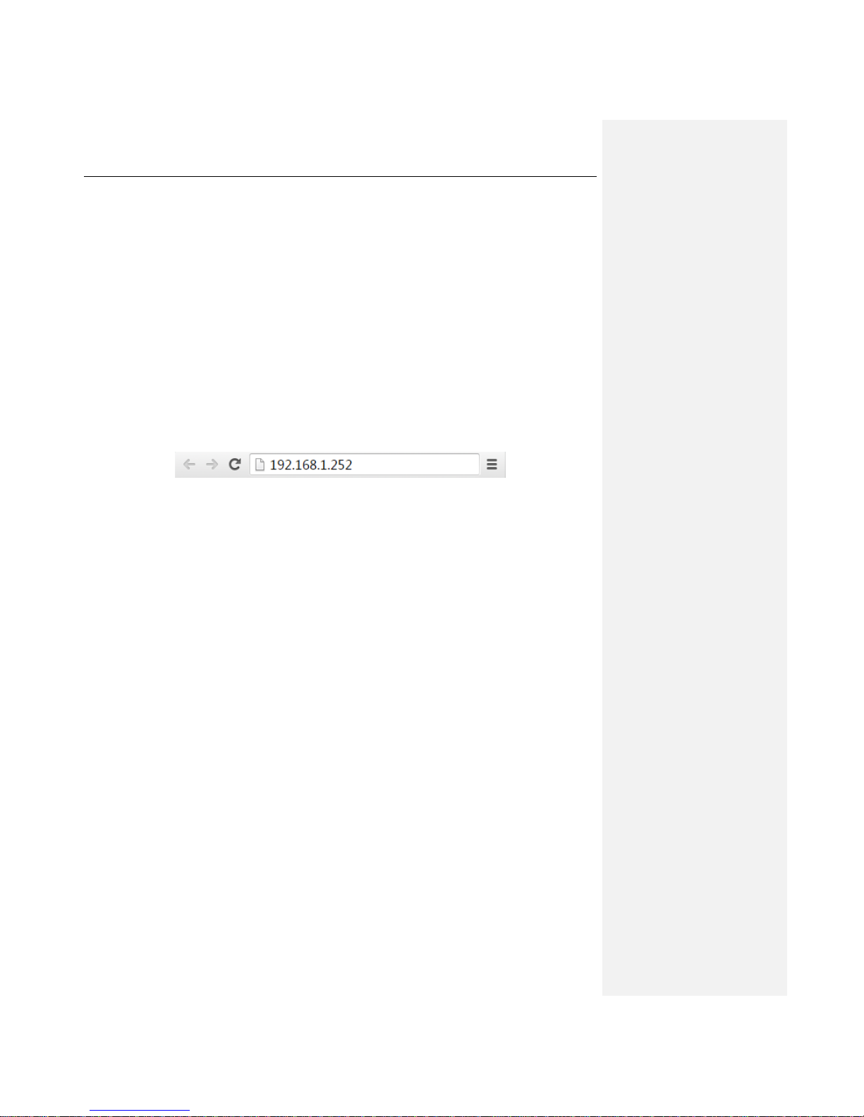
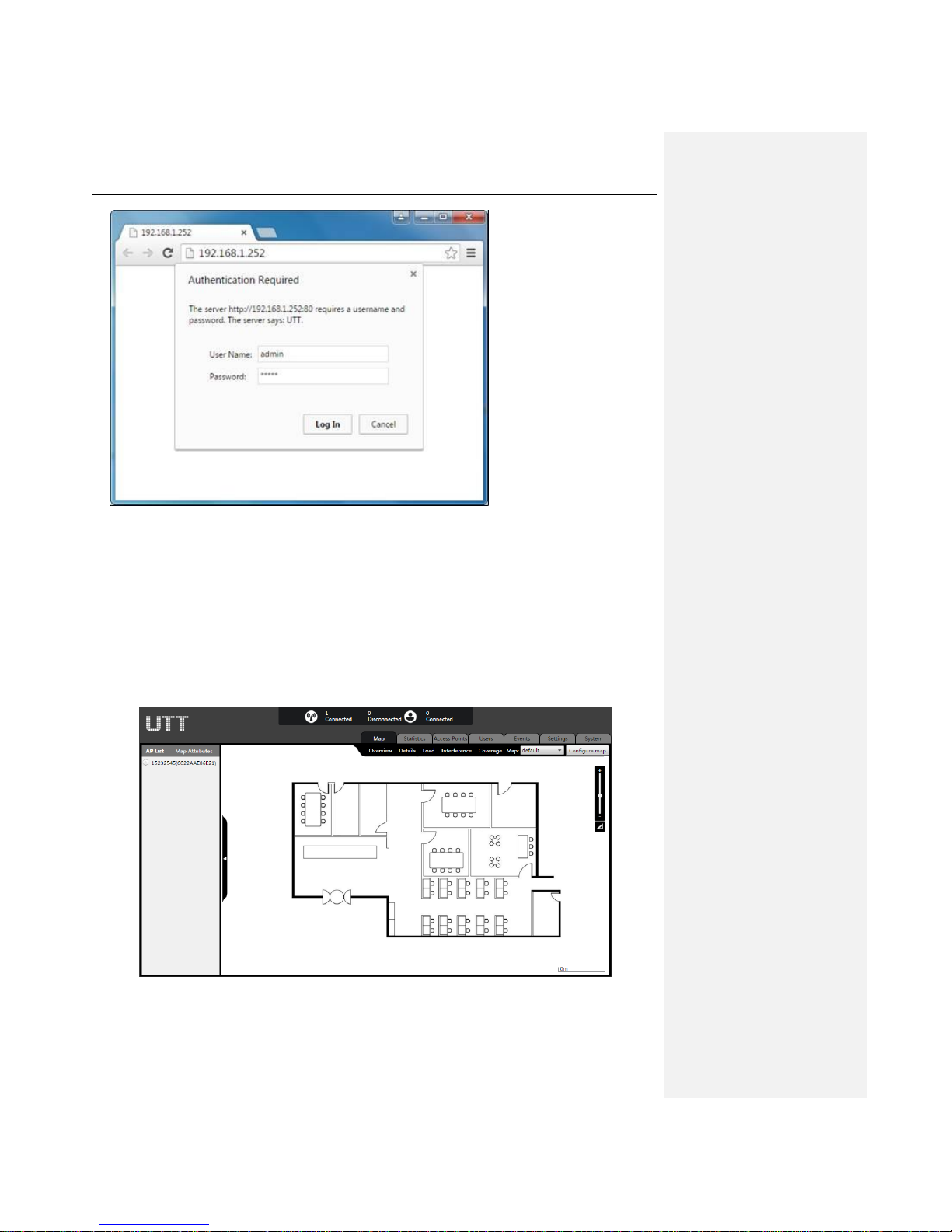
Step 1: For local access to the Device’s web-based utility, launch your web browser, and enter the
Device’s default IP address 192.168.1.252 in the URL field. Then press the Enter key.
Figure 2-1 Address Bar
Step 2: A login screen prompts you for Username and Password. Enter admin (case sensitive) in the
Username field, and enter admin in the Password field. Then click the Log In button.
Page 16
UTT Technologies Logging to the Device
http://www.uttglobal.com Page 11
Figure 2-2 Login Screen
Step 3: If the login is successful, the homepage appears, as shown below.
Figure 2-3 Web UI Home Page
Page 17
UTT Technologies Logging to the Device
http://www.uttglobal.com Page 12
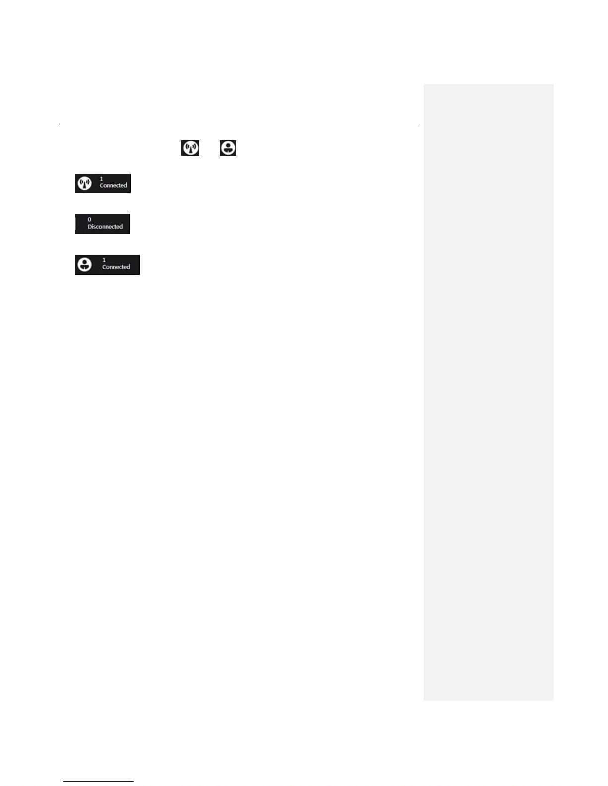
1) On top of the page there is the number of online and offline APs, and the number of online
wireless users, click the icon and to refresh the number of APs and online wireless
users. The icons on the top mean as follows:
: Number of currently online APs
: Number of currently offline APs
: Number of online wireless users, indicating the total number of
wireless users connected to the AP.
2) The main operation page is located in the center of the page, in which you can configure various
functions, view the related configuration, status, and statistics, etc.
If this is the first time for you to log into the Device, the main operation page will link directly to the
Map. In the next chapter, we will describe how to configure the basic parameters needed for the
Device to work properly.
Page 18
UTT Technologies Map Tab
http://www.uttglobal.com Page 13
Chapter 3. Map Tab
The Map shows the distribution of AP in the architectural plan, so as to manage the AP in a more
effective manner. In the Map, you can import several architectural plans, edit the AP distribution
locations, view the AP profile, details, and other information, as well as detect AP anomalies by
applying tests like interference testing, load testing, etc.
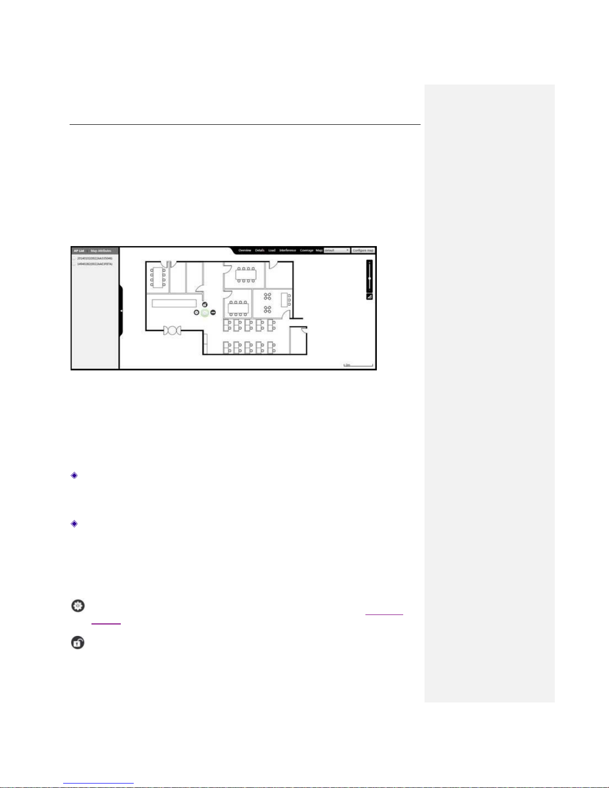
Figure 3-1 Page of Map
This page displays AP List and Map Attributes on the left side.
AP List: Displays the information of APs which are currently online and have not been added
to the map, including the MAC address, etc.. To add an AP to the map, please click and drag
the AP name to the actual position of the map on the right side. Note: The AP that has been
added to the map will not be displayed in the AP list.
Map Attributes: Displays the number of online APs, offline APs, users in the current Map,
and the name, description, size information of the Map . Here, the name and description of the
Map can be modified. The current Map can be saved to the local computer.
The center of this page is the display interface of the Map. All the APs you can manage will be
displayed on the Map if manually added. APs’ online status is represented by colors, green means
online, while gray means offline. Click the AP icon on the Map for single unit management.
: Click to manage the current AP. More information please refer to the chapter Single AP
Settings.
: Click to lock the location of AP on the map.
Page 19
UTT Technologies Map Tab
http://www.uttglobal.com Page 14
: Click to delete the current AP on the map.
3.1 Overview
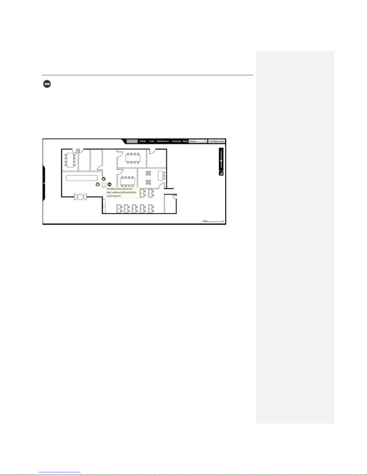
Click Map > Overview to display the AP's IP address, MAC address and serial number on the
map.
Figure 3-2 AP Overview
3.2 Details
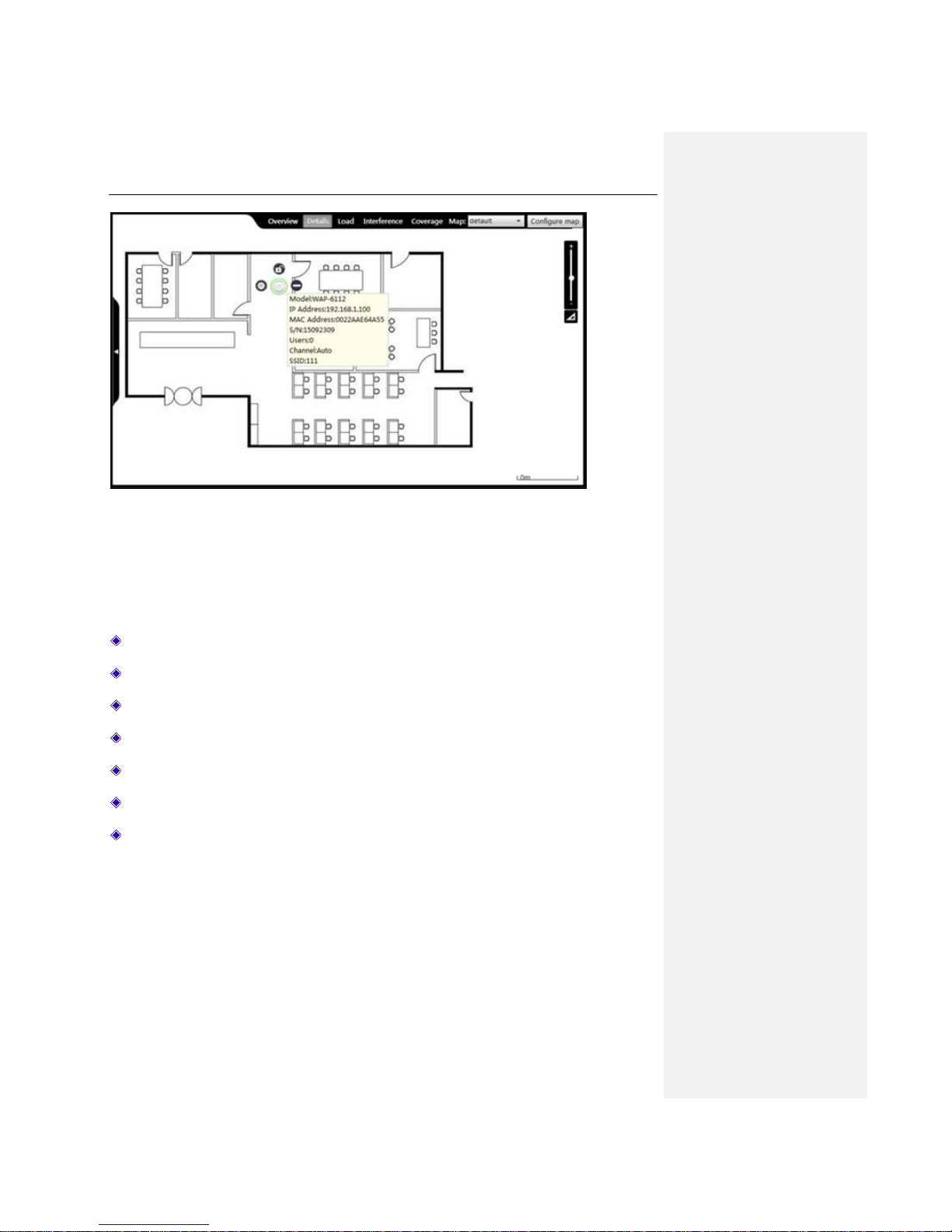
Click Map > Details to display the AP's Model name, IP address, MAC address, serial number,
online users, channel and SSID on the map.
Page 20
UTT Technologies Map Tab
http://www.uttglobal.com Page 15
Figure 3-3 AP Details
Model: Displays the name of the AP.
IP address: Displays the IP address of the AP.
MAC address: Displays the AP's MAC address.
S/N: Displays the AP's serial number.
Users: Displays the number of clients connected to the AP.
Channel: Displays the current wireless network frequency on which the AP works.
SSID: The SSID (Service Set Identification) is also known as the wireless network name,
which is used to uniquely identify a wireless network. It is case sensitive.
3.3 Load
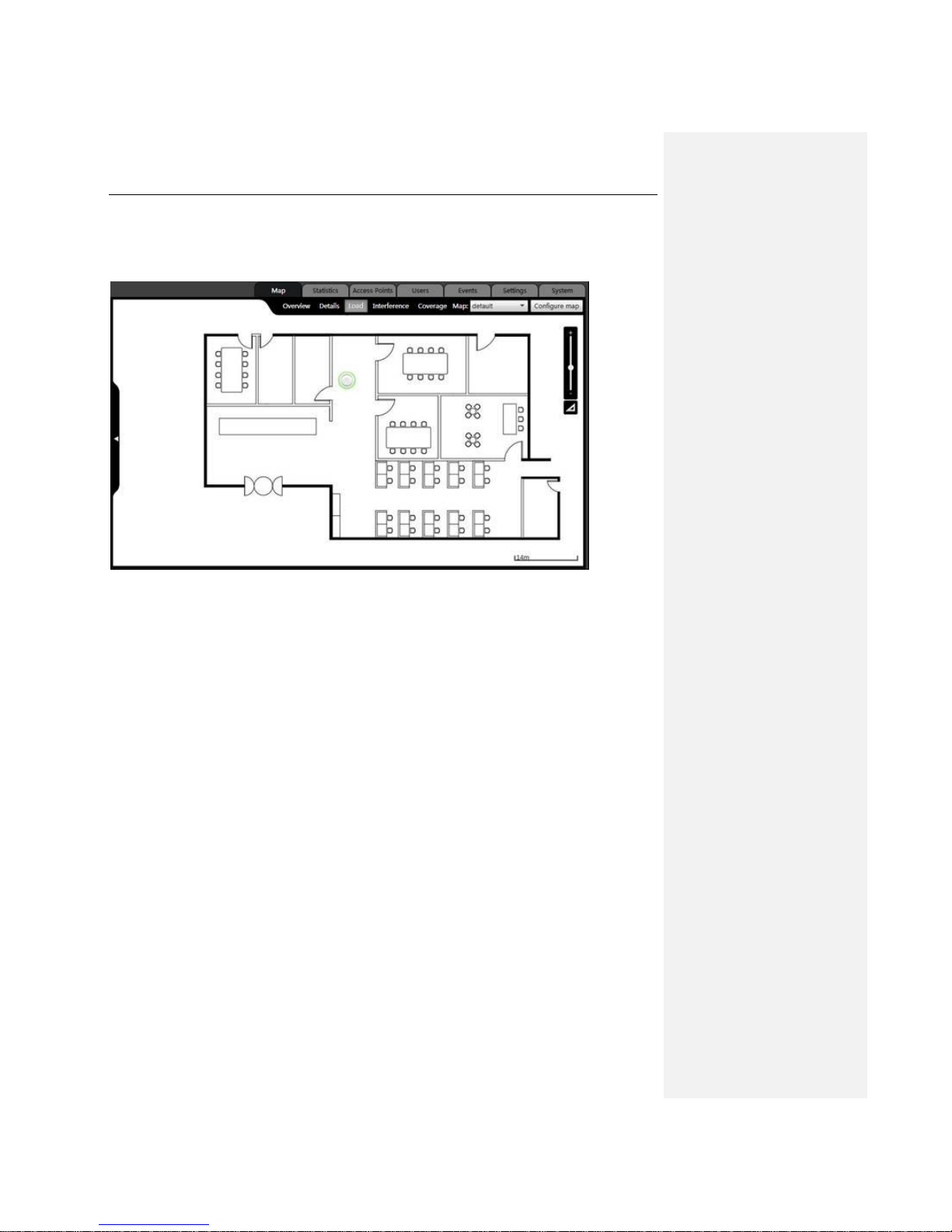
Click Map > Load to detect the proportion of the number of wireless clients connected to the AP to
the AP’s carrying capacity. The detection results are represented by colors:
Green: The proportion of the number of clients connected to the AP to the AP’s carrying
capacity is less than 40%.
Page 21
UTT Technologies Map Tab
http://www.uttglobal.com Page 16
Orange: The proportion of the number of clients connected to the AP to the AP’s carrying
capacity is more than/equal to 40% and less than 80%.
Red: The proportion of the number of clients connected to the AP to the AP’s carrying capacity
is more than/equal 80%.
Figure 3-4 Load
3.4 Interference
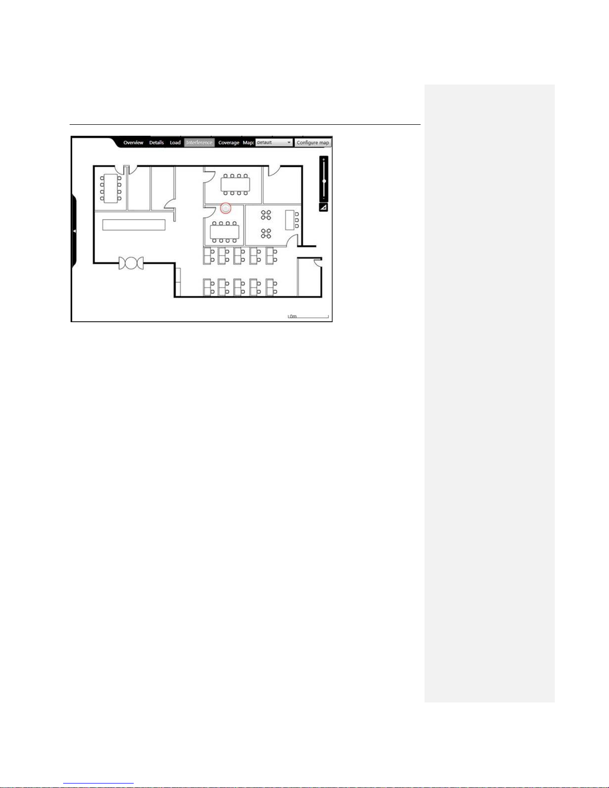
Click Map > Interference to check the interference degree in the same channel between the AP
and other devices near the AP. The detection results are represented by colors. Green means
there is a low disturbance; orange means there is a normal disturbance; red means there is a
serious disturbance.
Page 22
UTT Technologies Map Tab
http://www.uttglobal.com Page 17
Figure 3-5 Interference Detection
3.5 Coverage
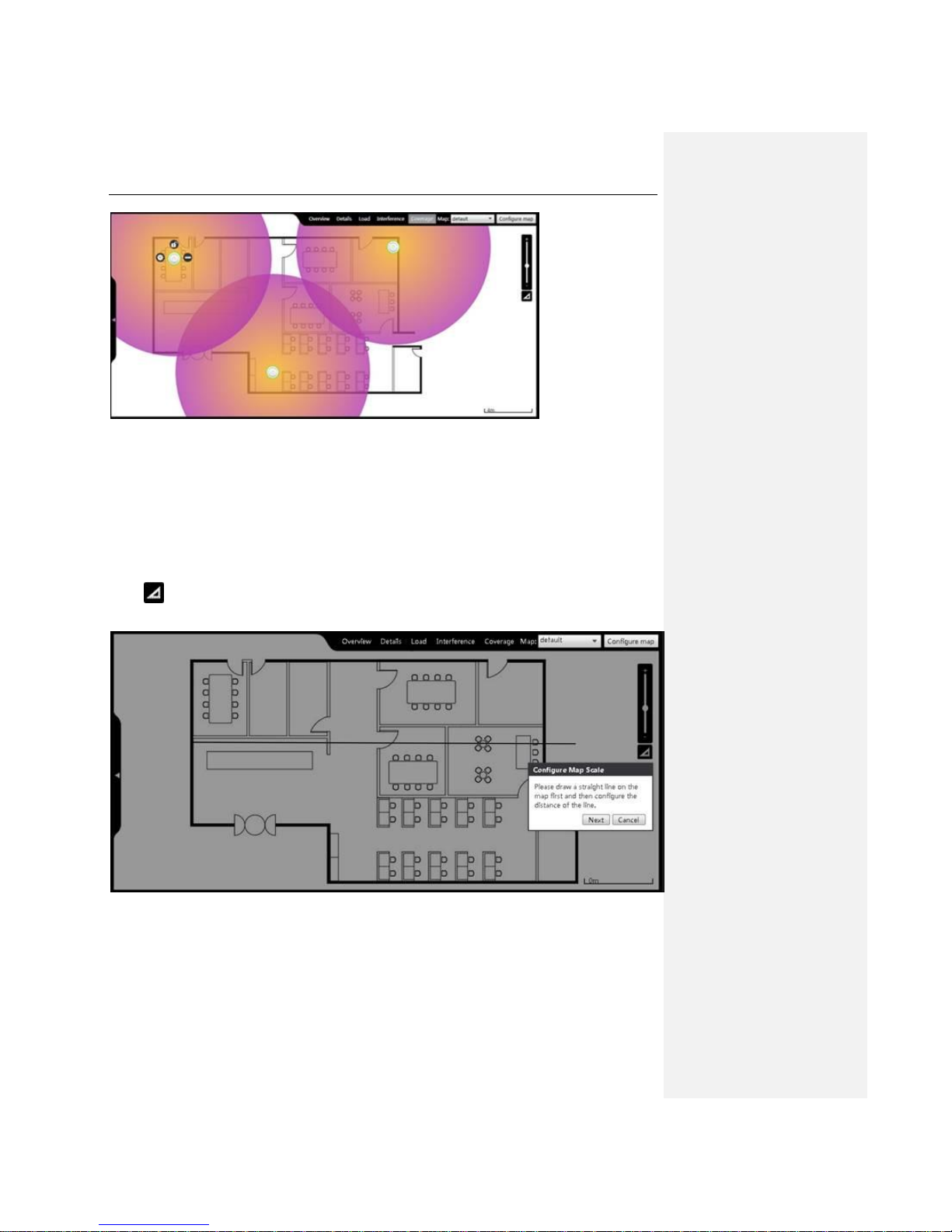
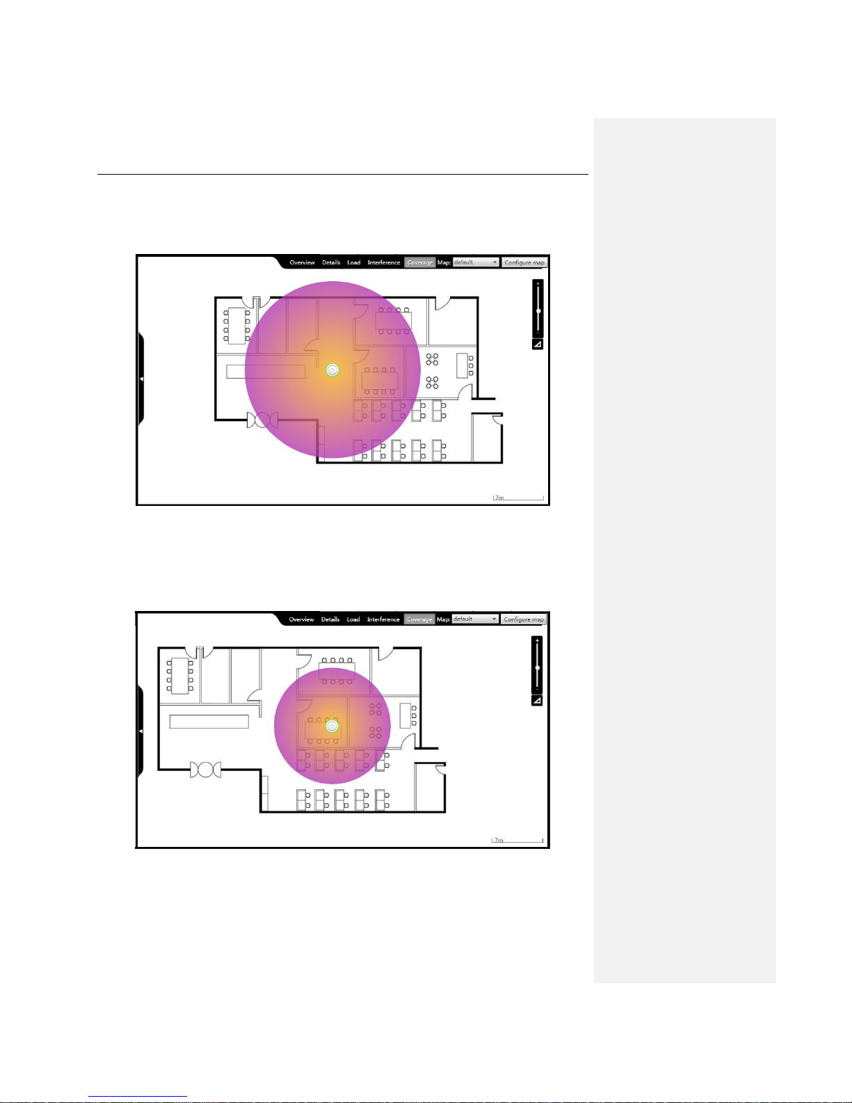
Click Map > Coverage to view the coverage area of the AP’s wireless signal. On the map, the
coverage area of the AP is displayed by a circle with the AP icon as its center.
Page 23
UTT Technologies Map Tab
http://www.uttglobal.com Page 18
Figure 3-6 AP Coverage
Before viewing the coverage area chart of AP for the first time, it is required to set the scale of the
map. The steps are as follows:
Click , draw a line on the map, and input the actual distance of the straight line drawn on the
Map in the pop-up dialog box, and click Next.
Figure 3-7 Configure Map Scale
Page 24
UTT Technologies Map Tab
http://www.uttglobal.com Page 19
Tips: The coverage distance of the Device is different while in different wireless modes. For
example, the coverage distance of the Device in 802.11n mode is wider than in 802.11g mode.
Following is the coverage figure of the Device in 802.11n mode:
Figure 3-8 Configure Map in 802.11n Mode
For comparison, we change the mode of the Device to 802.11g, the coverage area of the Device is
as following:
Figure 3-9 Configure Map in 802.11g mode
Page 25
UTT Technologies Map Tab
http://www.uttglobal.com Page 20
3.6 Map
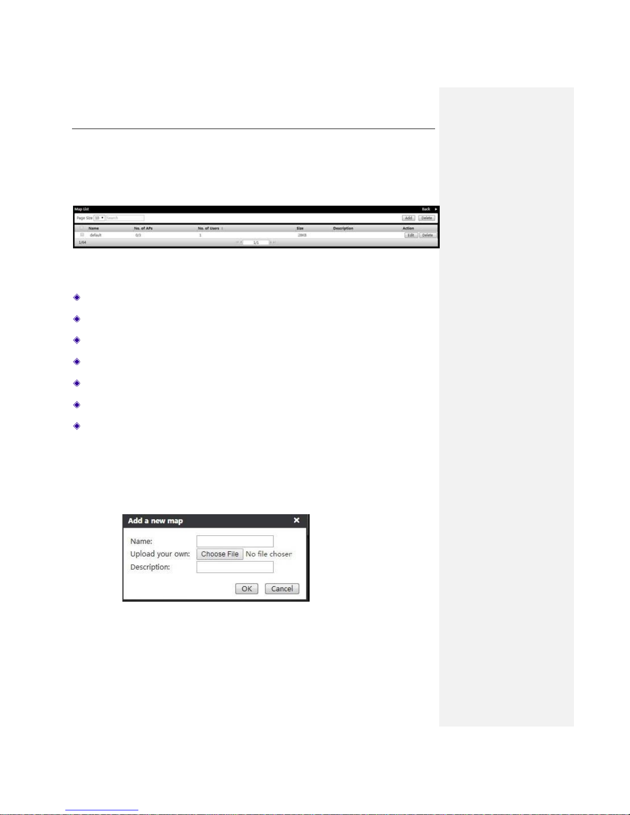
The Map is displayed in the architectural plan in the middle of the page. You can choose different
maps from the Map drop-down list, and can manage the maps. Click on Configure Map button to
enter the interface as shown below.
Figure 3-10 Import Drawing Interface
Name: Displays the map name.
No. of APs: Displays the number of APs on the map.
No. of Users: Displays the number of the connected terminal devices on the map.
Size: Displays the map size.
Description: Displays the description of the map.
Edit: Click to modify the drawing name and note information.
Delete: Delete the map.
On the top right corner of the page, there are two buttons, Add and Delete. You can add new
maps and delete maps in batch.
Add maps: Click the Add button to open up the dialog box as shown in the figure below,
upload maps, enter the name and description of the maps, then click the OK button to save
the maps. Notes: The map name supports upper/lowercase letters, numbers, underline. The
picture uploaded should be in JPG format.
Figure 3-11 Map Importing
Delete maps in batch: Select the maps to be deleted, and click the Delete button on the top
Page 26

UTT Technologies Map Tab
http://www.uttglobal.com Page 21
right of the page.
Page 27
UTT Technologies Statistics Tab
http://www.uttglobal.com Page 22
Chapter 4. Statistics Tab
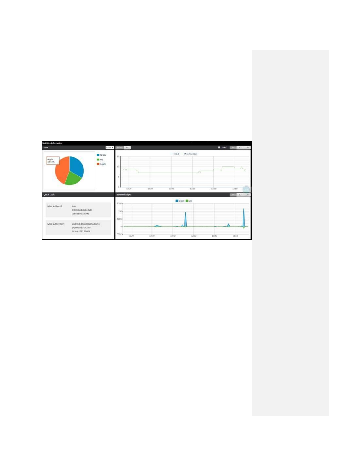
In the Statistics page, the administrator can view four kinds of statistics: statistics of user number
classified by SSID, radio frequency, map, or operating system; statistics of online wireless
clients/APs; the most active wireless client and AP; traffic statistics.
Figure 4-1 Statistics Chart
1) On the upper left corner of the figure, the statistics about currently online wireless clients is
displayed in sector diagram, and you can choose to display them by classification of SSID, RF,
Map or OS.
2) On the upper right corner of the figure, the statistics about currently online wireless clients/APs
is displayed in the line chart. It can be displayed by hours, days or weeks. The horizontal axis
represents time, while the vertical axis represents the number of users.
3) The lower left corner of the figure shows the information about the most active wireless client
and AP, including the name of that device, download traffic and upload flow. Click the name of the
wireless client to view more information about it. Click the name of the AP to configure that AP.
With regard to how to configure the AP, please refer to chapter Single AP Settings.
4) The lower right corner of the figure shows the total input/output data of all APs within a specified
time period.
Here are three examples to for us to learn more about the features of the Statistics page.
Page 28
UTT Technologies Statistics Tab
http://www.uttglobal.com Page 23
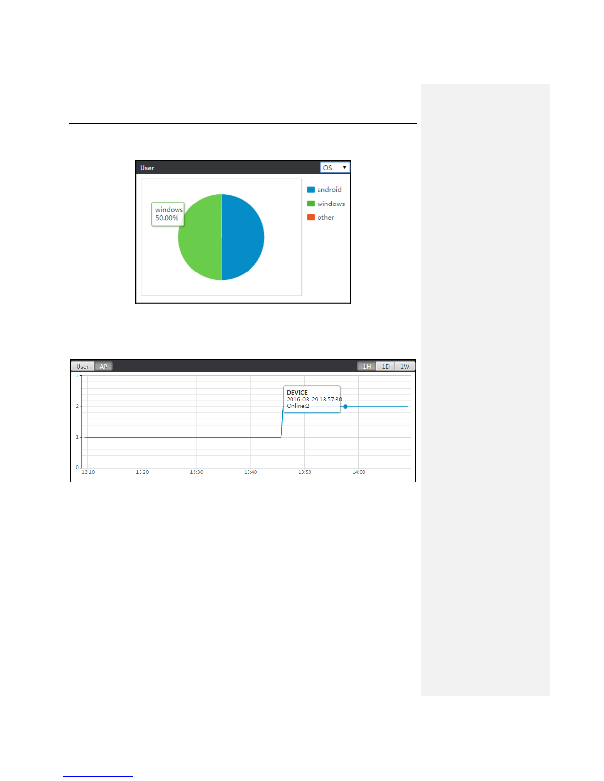
Example 1: Following is the user statistics classified by operating system. It shows clients with
Windows OS take up 50% of all clients.
Figure 4-2 User Statistics Chart_OS
Example 2: Following is the AP number statistics chart, show there are 2 online APs at 2016-3-29
13:57:30.
Figure 4-3 AP Statistics Chart
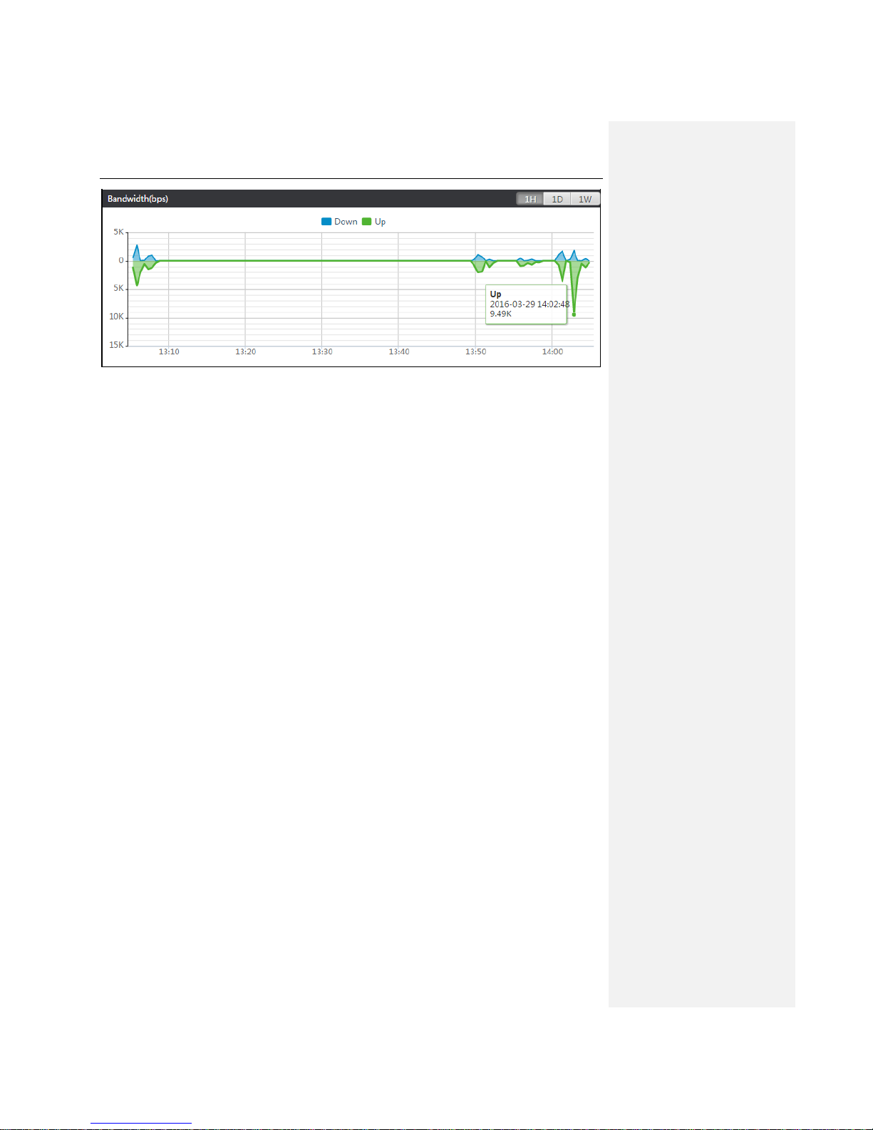
Example 1: Following is the traffic statistics chart, showing that the total up traffic from all clients is
9.49K at 2016-03-29 14:02:48.
Page 29
UTT Technologies Statistics Tab
http://www.uttglobal.com Page 24
Figure 4-4 Bandwidth Statistics Chart
Page 30

UTT Technologies Access Point Tab
http://www.uttglobal.com Page 25
Chapter 5. Access Point Tab
5.1 AP Controller
The Device can implement configuration, manage and monitor the entire wireless network in a
centralized manner. AP management includes: transmitting firmware, assigning configuration,
modifying parameters, etc.
The discovery between the Device and a UTT AP can penetrate three-layer network devices. The
Device can manage APs from the second or third layer of the network.
This chapter mainly introduces the related concepts about centralized management of AP and
relative management functions including AP management, distributed WLAN, the configuration of
AP RF templates, AP configuration templates, AP software management, etc.
5.1.1 Terminology
Client: A PC, laptop, or other terminals with a wireless Network Interface Card.
STA (station): A wireless network device in the network node.
WLAN (Wireless Local Area Network): A WLAN is a type of local-area network that uses
high-frequency radio waves rather than wires to transmit data.
AC (Access Controller): An AC, also known as WLAN controller, WiFi Controller, wireless
Controller, is a network device that is used to control and manage access points in the network.
AP (Access Point): An AP is a network device that acts as a base station for the wireless LAN, and
acts as a bridge between wired and wireless networks.
Fat AP: A standalone AP that independently controls and manages wireless clients.
Fit AP: A simple AP that relies on AC to control and manage wireless clients. The access points in
Fit AP mode can retrieve firmware and configuration file from AC.
Intra-Controller Roaming: Intra-controller roaming occurs when a wireless client roams between
APs managed by the same AC.
Layer 2 Roaming: Layer 2 roaming occurs when a wireless client roams between APs on the
same subnet and VLAN.
Page 31
UTT Technologies Access Point Tab
http://www.uttglobal.com Page 26
5.1.2 Working Principle
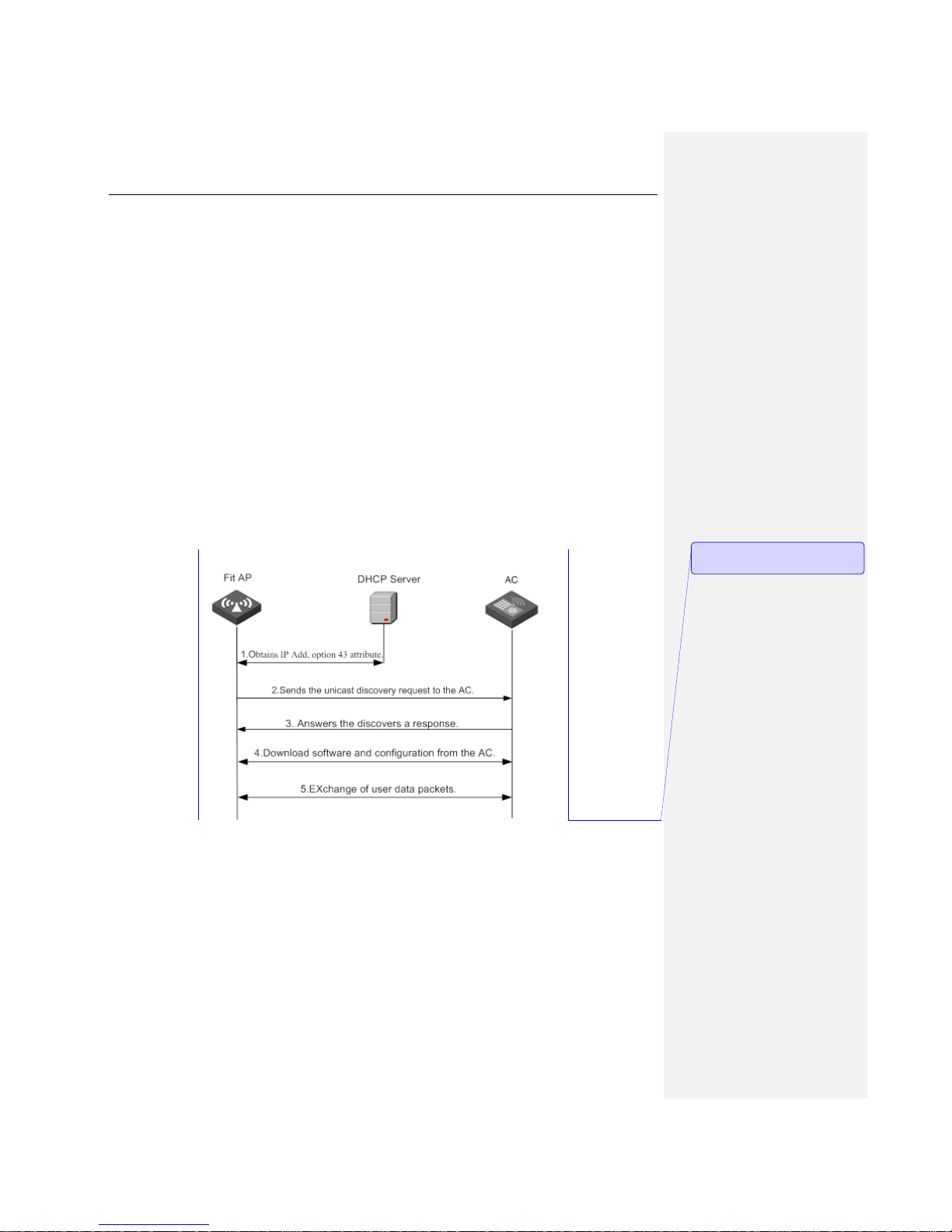
The figure below shows the communication process between a Fit AP and the AC.
For the implementation of Fit AP + AC solution, the first and crucial step is the registration of a Fit
AP behind a three-layer switch. The AC can manage a Fit AP only after the Fit AP is successful
registered. In the practical cases, it is common for AC+Fit AP to accomplish the registration by
crossing a three-layer network. Our Device has three ways of finishing the task:
The first way needs the help of a local DNS server. You need to set up a DNS server on the local
area network and bind the IP address of the AC to a specific domain name on the DNS server.
After that, please configure the domain name as the address of the AC on the AP. In this way,
when the AP requests for the address of the AC, the DNS server will response with the IP address
of the AC.
The second way is configuring AC’s address on the AP directly, this is relatively simple.
The third way is by making use of DHCP Option 43. Fit AP can directly obtain the IP address of the
AC through the Option 43 attribute of DHCP, thus completing the registration on the AC. The
specific process is shown in the figure below:
Figure 5-1 AC and AP centralized manager communicate on layer 2
When the Fit AP and AC are connected crossing a three layers network, the registration procedure
is as follows:
1) Fit AP obtains an IP address and the option 43 attribute (which carries the IP address of the AC)
from the DHCP server.
2) Fit AP will obtain the IP address of the AC from the option 43 attribute, and then send a unicast
discovery request to the AC.
批注 [周瑶3]: 图片中的文字需要修
改
Page 32

UTT Technologies Access Point Tab
http://www.uttglobal.com Page 27
3) The AC that received the discovery request packet will check if the Fit AP has access to it, and
answer the request if the Fit AP is successfully verified.
4) Fit AP downloads the latest version of firmware from AC.
5) Fit AP downloads the latest configuration from AC.
6) Fit AP begins to work normally to exchange user data with AC.
Notes:
(1) While the AP’s configuration file is modified, for instance, it joins a WLAN, AC will save the
modified configuration file locally and send it to the AP, while the configuration file will be deleted
after AC powers off.
(2) AC will delete the saved configuration file after resetting the AP to factory default settings
remotely.
(3) The configuration file will be saved on the AP too, that means, when AC powers off, the
configuration file will not lose.
(4) AP can start transmitting user data immediately after successfully obtaining the firmware and
configuration file.
5.1.3 Layer 2 Roaming
Mobility, or roaming, is a wireless client’s ability to move from one AP’s coverage area to that of
another without interruption in service or loss in connectivity.
AP supports layer 2 roaming, which allows wireless clients to roam across APs on the same
subnet and VLAN. To implement layer 2 roaming, you need to assign the same WLAN parameters
to the APs, so that they have the same SSID, and are on the same subnet and the same VLAN.
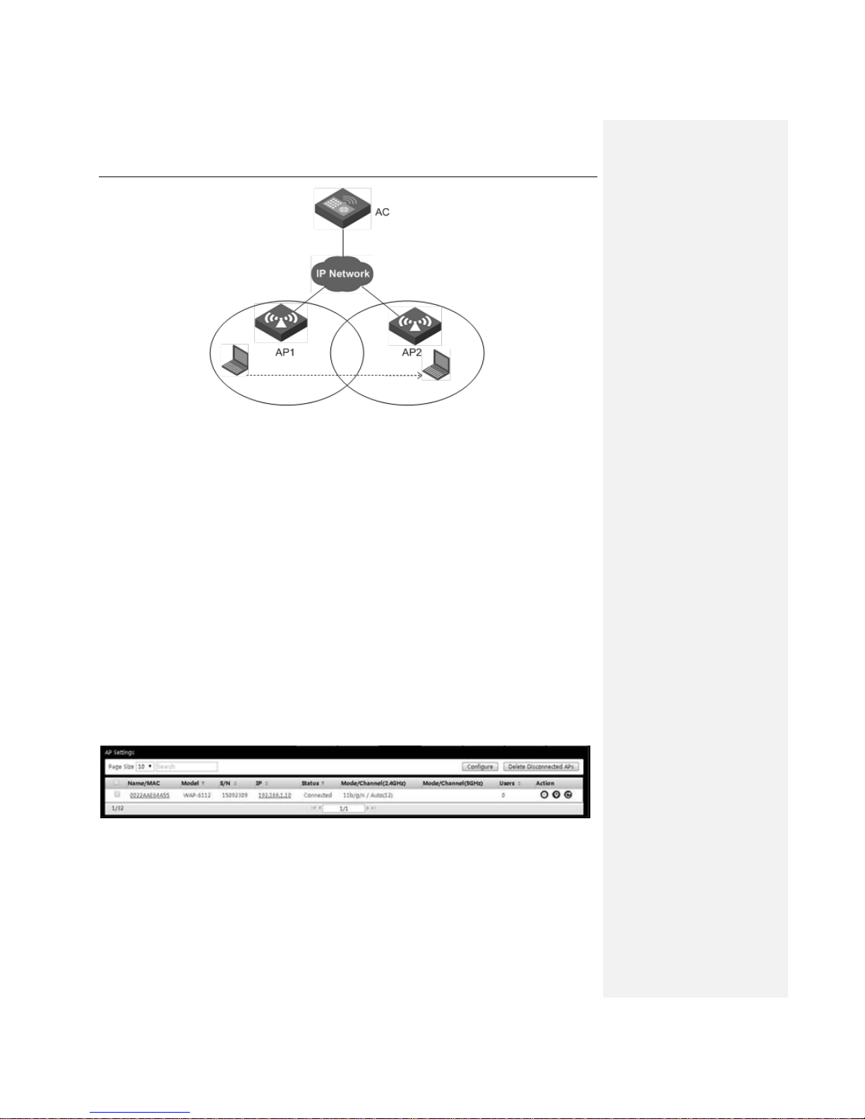
The following figure shows intra-controller layer 2 roaming, which occurs when the coverage of the
two APs overlap.
Page 33
UTT Technologies Access Point Tab
http://www.uttglobal.com Page 28
Figure 5-2 Layer 2 Roaming
As shown in the above figure, AP1, AP2 belong to the same VLAN and are associated with an AC.
1) A terminal is wirelessly connected to AP1, and AP1 connects with the AC.
2) The terminal disconnects with AP1, and roams into the network of AP2 which is connected to
the same AC and in the same VLAN with AP1.
3) The process which the terminal shifts to AP2 from AP1 is referred to as two-layer wireless
roaming.
The way of implementation: Configure a WLAN on the Device and enable the two-layer roaming
function by adding AP1, AP2 into the same WLAN; when the quality of wireless signal reaches the
roaming threshold configured, the two-layer wireless roaming will be implemented.
5.2 AP Settings
Click the Access Points menu to enter the page of AP, and the administrator can view all the APs
in the current intranet, and to locate, restart, set in batch the online APs, or to delete all offline APs.
Figure 5-3 AP Settings
Batch management: After selecting multiple APs, click Configure to make batch operations
to APs, like modifying login passwords, restarting, restoring the factory settings, etc.
Delete Disconnected APs: Click Delete Disconnected APs to remove all the offline APs.
Page 34
UTT Technologies Access Point Tab
http://www.uttglobal.com Page 29
Name/MAC: Displays the name or MAC address of the current AP. Click on the MAC address
to configure the AP. For more information about how to configure the AP, please refer to
Single AP Settings.
Model: Displays the model of the current AP.
S/N: Displays the serial number of the current AP.
IP: Displays the IP address of the current AP.
Status: Displays the status of the current AP, namely, online and offline.
Model/Channel: Displays the channel used by the current AP. When the AP channel is
configured to Auto, the actual channel used will also be displayed.
Users: Displays the number of wireless clients currently connecting to the AP.
Action: Managing, locating and restarting AP.
: To manage the current AP, please refer to Single AP Settings.
: Location button, to locate the AP on the architecture map.
: Restart the current AP.
Notes: The AP list only supports displaying the information of UTT WA series AP.
5.2.1 Batch Settings
When there are multiple APs to be performed with the same action, for example, to be set to the
same RF template, changing the administrator password, updating the firmware, joining the same
WLAN, etc., you can use the batch setting function.
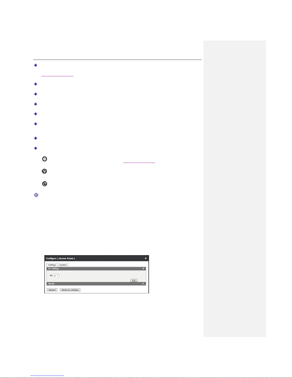
Click on the Access Points menu, select multiple APs, and click Configure on the top right
corner of the page, to do batch setting.
Page 35
UTT Technologies Access Point Tab
http://www.uttglobal.com Page 30
Figure 5-4 Batch settings
RF Setting: Select the RF template and click the OK button. Note: RF can only be set in
batch.
WLAN: Choose the WLAN to be distributed and click Join WLAN.
System Settings: Enter the administrator password and click OK.
Firmware Upgrade: First download the latest version of firmware from the UTT official
website, and then upload the firmware locally to complete the system upgrade.
5.2.2 Single AP Settings
Make configurations for a single AP. Click behind the AP name to view the details of the AP
and setup AP.
5.2.2.1 Details
In the AP list, click the Name/MAC address of AP to show the AP details interface, in which you
can view more information about the system, statistics, radio frequency of the current AP.
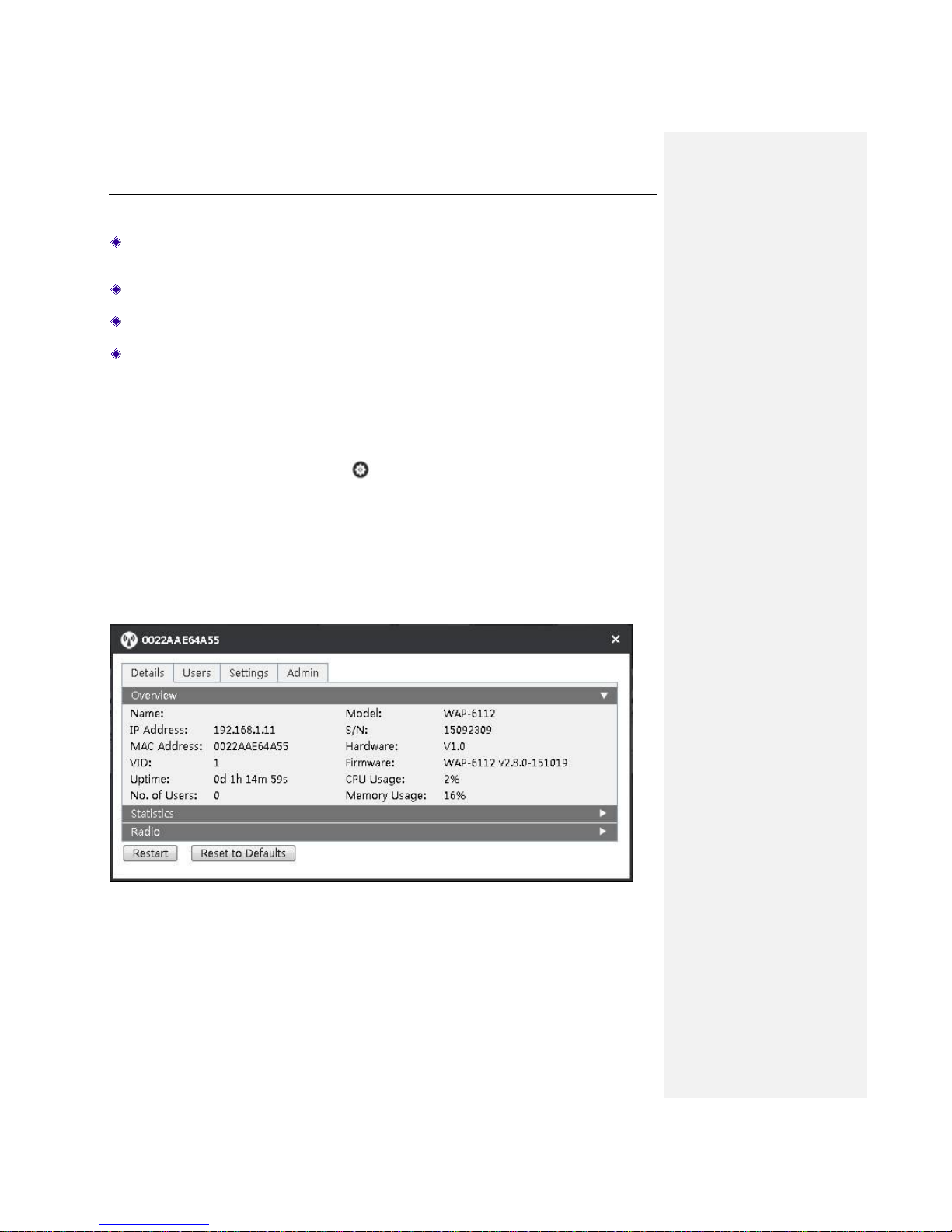
1) Overview
Figure 5-5 System information
Page 36

UTT Technologies Access Point Tab
http://www.uttglobal.com Page 31
Name: Displays the name of the current AP.
IP address: Displays the IP address of the current AP.
MAC Address: Displays the MAC address of the current AP.
VID: Displays the VLAN ID of the current AP, with a range of 1-4094.
Uptime: Displays the running duration of the AP from start to now.
No. of Users: Displays the number of wireless clients connecting to the current AP.
Model: Displays the model name of the AP.
S/N: Displays the serial number of the AP.
Hardware: Displays the hardware version of the AP.
Firmware: Displays the firmware version of the AP.
CPU Usage: Displays the usage rate of CPU.
Memory Usage: Displays the usage rate memory.
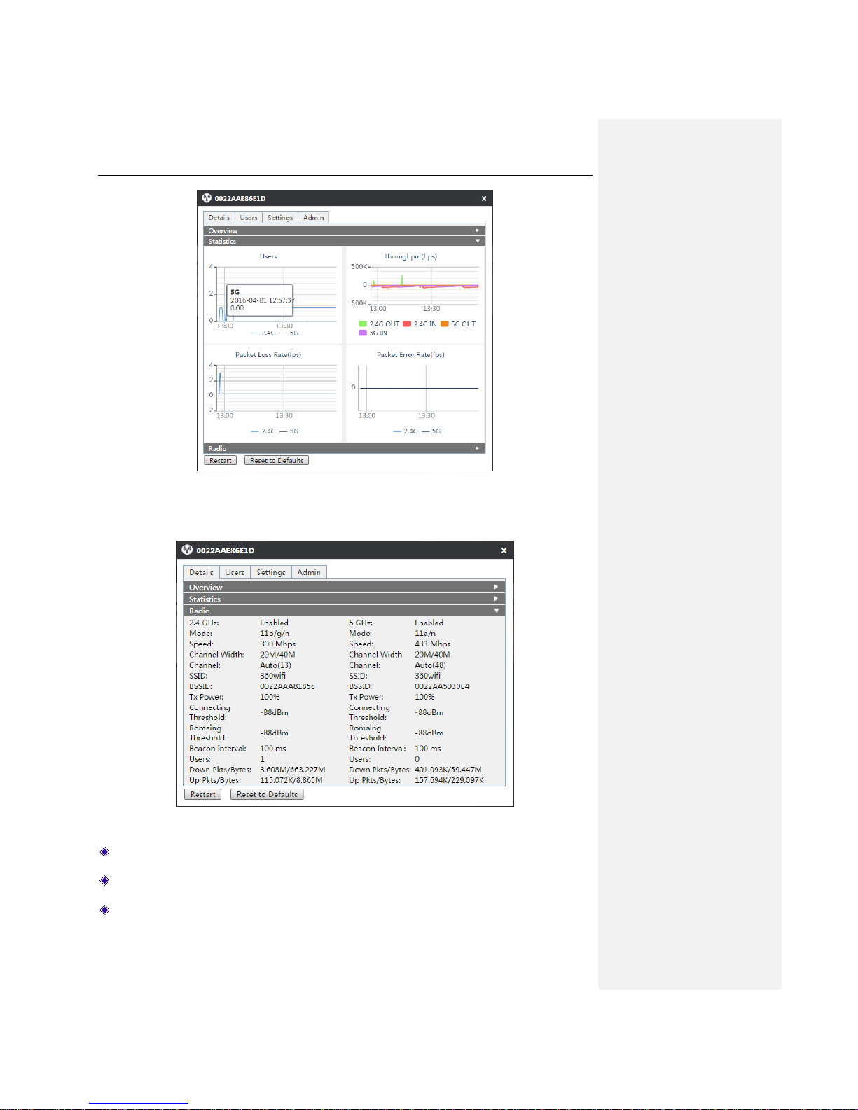
2) Statistics
View the number of users connecting to the current AP at specific time points, wireless throughput,
packet loss rate and packet error rate.
Wireless throughput: The wireless upload, download rate of the current AP.
Packet loss rate: Refers to the ratio of the lost packets to the transmitted data sets in the process
of transmitting data packets.
Packet error rate: Refers to the ratio of the received error packets to the transmitted data sets in
the process of transmitting data packets.
Page 37
UTT Technologies Access Point Tab
http://www.uttglobal.com Page 32
Figure 5-6 Statistics
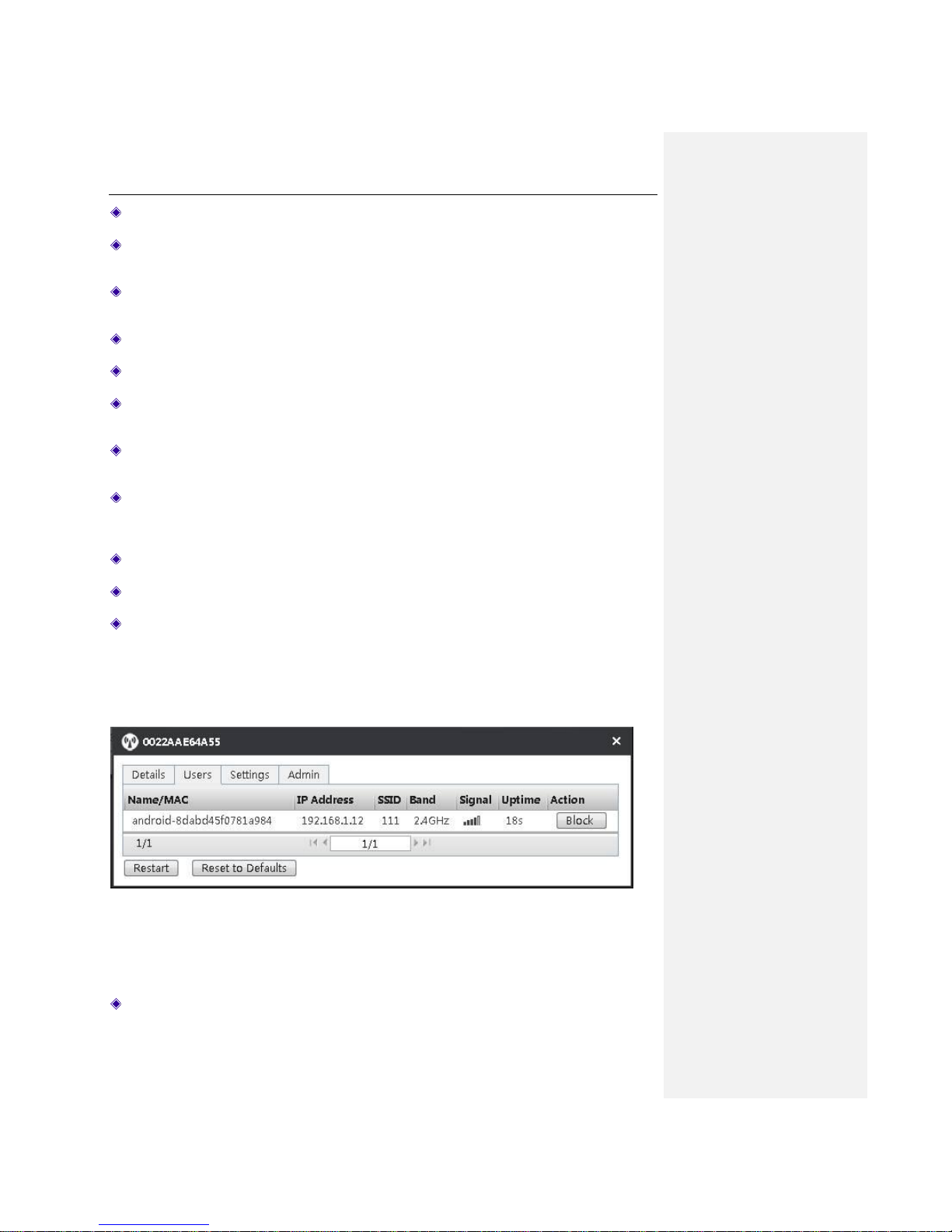
3) Radio
Figure 5-7 Radio Frequency Information
2.4GHz or 5GHz: Displays if the AP’s 2.4G/5G function is enabled.
Mode: Displays the AP’s wireless working mode.
Speed: Displays the AP’s wireless speed rate.
Page 38
UTT Technologies Access Point Tab
http://www.uttglobal.com Page 33
Channel Width: Displays the channel bandwidth occupied by the wireless data transmission.
Channel: Displays the channel used by the current AP. When AP channel is configured to
Auto, the actual channel used will also be displayed here.
SSID: The SSID (Service Set Identification) is also known as the wireless network name,
which is used to uniquely identify a wireless network. It is case sensitive.
BSSID: Displays AP’s wireless MAC address.
Tx Power: Displays the AP transmission power.
Connecting Threshold: The minimum threshold set for the STA to connected to the AP. If
the quality of signal is lower than this value, the AP will not allow the STA to connect to it.
Roaming Threshold: The roaming threshold set for the connected STA. If the quality of
signal is lower that this value, the AP will disconnect the STA.
Beacon Interval: AP will send Beacon frames to the network regularly, and synchronize them
with the network. Beacon interval is the periodic time interval for sending Beacon frames, with
the range of 20 ~ 999 milliseconds.
Users: Displays the number of connected wireless clients.
Down Pkts/Bytes: Displays the number of received packets/bytes.
Up Pkts/Bytes: Displays the number of sent packets/bytes.
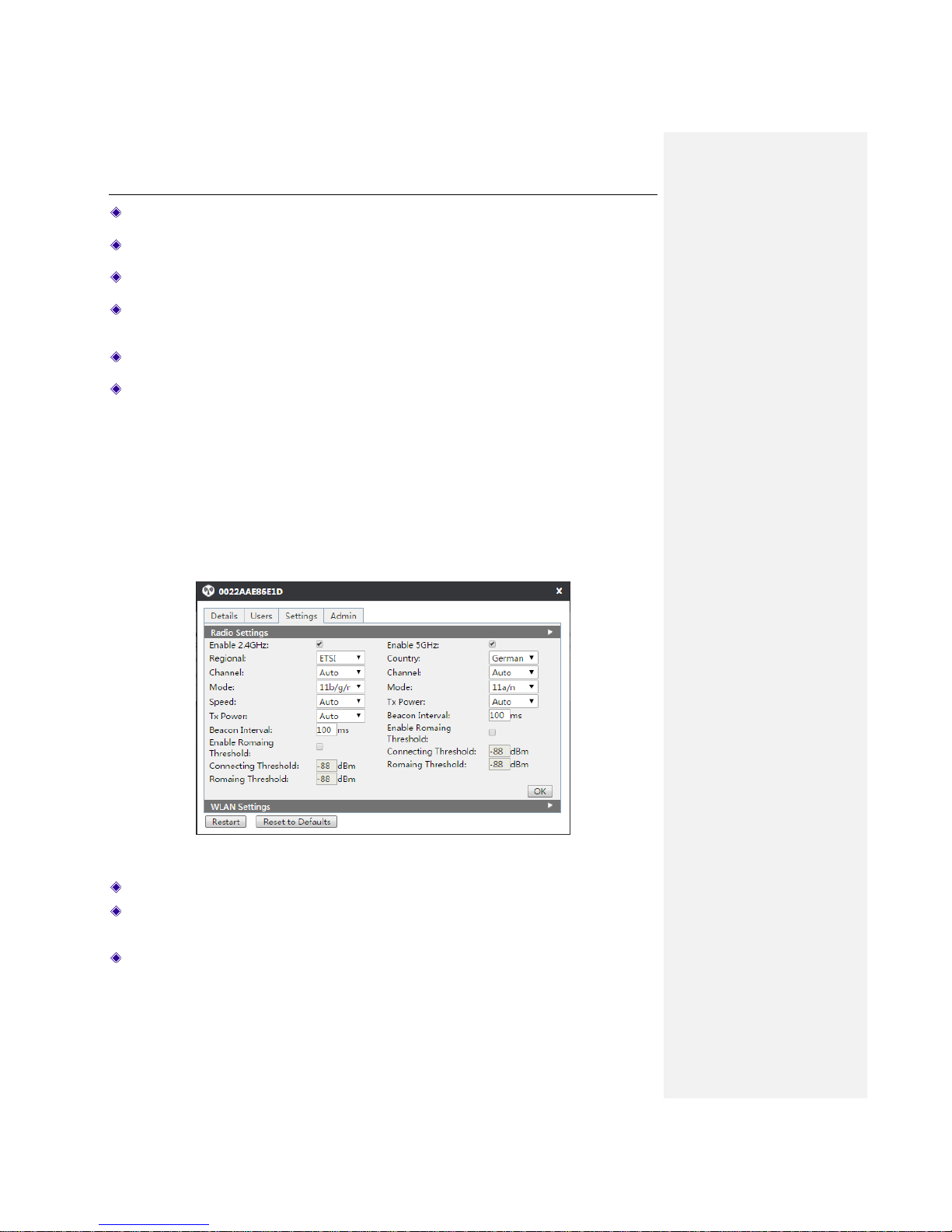
5.2.2.2 Users
Click Access Points > AP name > Users to enter the page as shown in the figure below. The
information about the client connected to the AP displays on the page.
Figure 5-8 Users
Name/MAC: Displays the name or MAC address of the wireless client.
Page 39
UTT Technologies Access Point Tab
http://www.uttglobal.com Page 34
IP Address: Displays the IP address of the wireless client.
SSID: The name of the wireless network currently accessed by the wireless client.
Band: Displays the frequency band to which the wireless client is connected.
Signal: Strength of wireless signals. When a wireless signal has a full occupied lattice, it
means the signal is strong.
Uptime: Displays the online duration of the wireless client.
Action: Click Block to add the current wireless client into the blacklist.
5.2.2.3 Settings
Click Access Points > AP name > Settings to enter into the AP Settings page, and you can
modify the related parameters of RF settings and distribute WLAN settings.
1) Radio Settings
Set the related parameters according to the actual needs, and click OK to complete the setting of
RF parameters.
Figure 5-9 Radio Frequency Settings
Enabling 2.4 GHz or 5GHz: Select it to enable the 2.4GHz/5GHz frequency band.
Regional or Country: Select the correct regional standard from the drop-down list. Different
regions will use different channels.
Channel: Select the frequency bands in which the wireless network works. It provides an
automatic option, which means that the Device can automatically select the optimal frequency
band. The wireless devices in the same frequency band will interfere with each other. If there
are multiple wireless devices around the AP, please select a frequency band different from
that of other wireless devices when setting the channel.
Page 40
UTT Technologies Access Point Tab
http://www.uttglobal.com Page 35
Mode: Select the wireless working mode of AP. It is recommended to use the 11 b/g/n mode.
Speed: Select the wireless data transmission rate of AP.
Tx Power: Select the transmission power for wireless data transmission of AP.
Beacon Interval: AP will send Beacon (Beacon) frames to the network regularly, and
synchronize them with the network. Beacon interval is the periodic time interval for sending
Beacon frames, with the value range of 20 ~ 999 milliseconds.
Enable Roaming Threshold: if enabled, the associated threshold and roaming threshold can
be set.
Connecting Threshold: The minimum threshold set for the STA to connected to the AP. If
the quality of signal is lower than this value, the AP will not allow the STA to connect to it.
Roaming Threshold: The roaming threshold set for the connected STA. If the quality of
signal is lower that this value, the AP will disconnect the STA.
Roaming means that the wireless client can detect other devices with strong wireless signal and
connect to them when it leaves the coverage area of the current AP signal. Threshold refers to the
minimum threshold for the AP to disconnect a client. When signal strength is lower than the set
threshold, the roaming function is enabled.
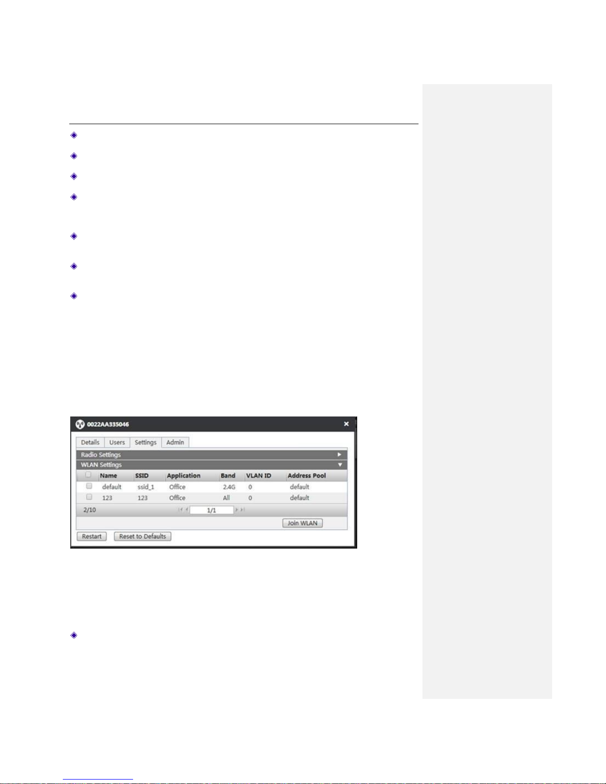
2) WLAN Settings
Select the WLAN to be distributed, and click Join WLAN to distribute a WLAN to the current AP.
Note: One AP can be distributed with at most four WLAN.
Figure 5-10 WLAN Settings
Name: Displays the name of the WLAN.
Page 41
UTT Technologies Access Point Tab
http://www.uttglobal.com Page 36
SSID: The SSID (Service Set Identification) is also known as the wireless network name,
which is used to uniquely identify a wireless network. It is case sensitive.
Application: Displays the application type.
Band: The Device Supports two frequency bands, 2.4GHz / 5GHz. ALL means that both
frequency bands will are set.
VLAN ID: Displays the VLAN value, which range between 1-4094.
Address Pool: Displays the name of the address pool. For the details address pool
configuration, please refer to VLAN Settings.
5.2.2.4 Admin
In this interface, the working mode of AP, the way to obtain the IP address of AP and upgrading of
the AP firmware can be set or done.
There are two AP working modes, Fit AP and Fat AP. In the Fat AP mode, AC can manage the AP;
in the Fat AP mode, the AP can be configured independently without the help of AC. It is
recommended to restart your Device for the configuration to take effect if the Device is to switch
modes no matter which mode it is working under.
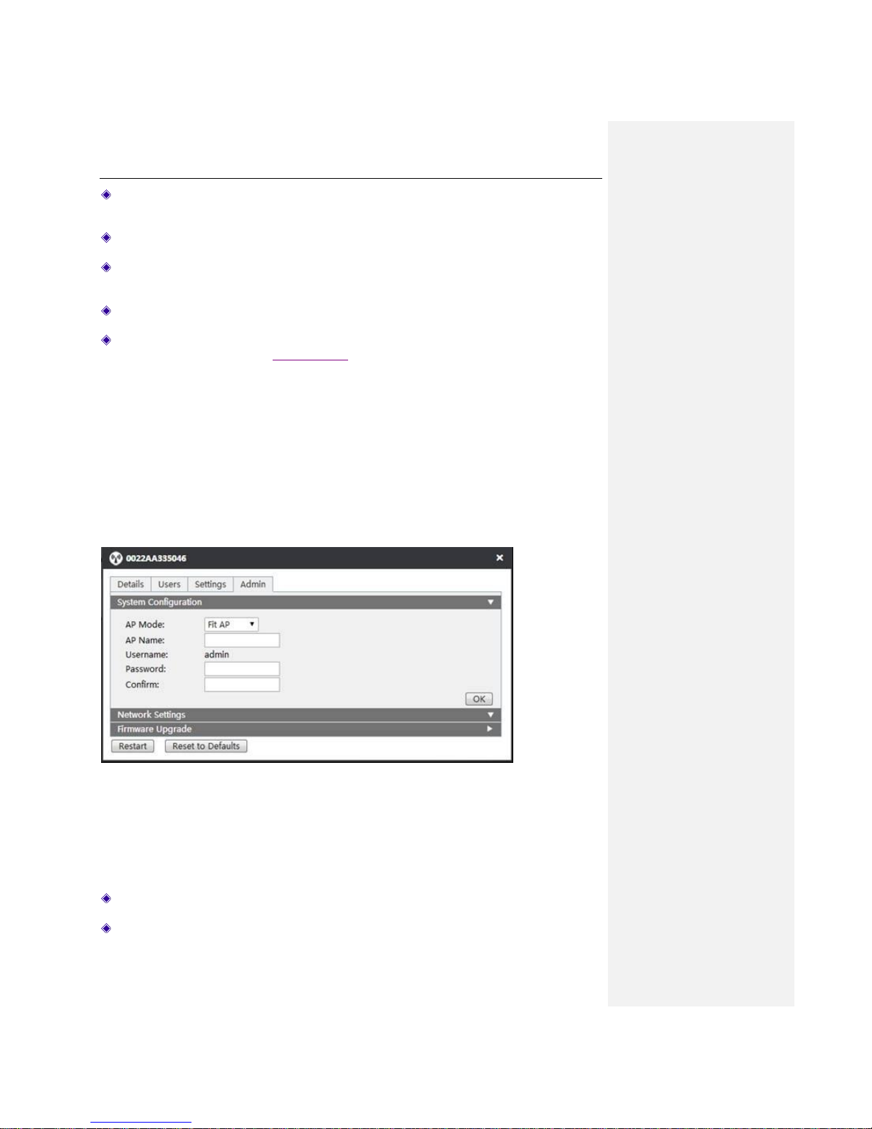
1) System Configuration
Figure 5-11 System Settings
AP Mode: Select the AP’s working mode. There are two modes: Fat AP and Fit AP.
AP Name: Specify the name of the AP.
Page 42
UTT Technologies Access Point Tab
http://www.uttglobal.com Page 37
Username: Displays the name of the currently logged administrator.
Password: Specify the password.
Confirm: Enter the password again.
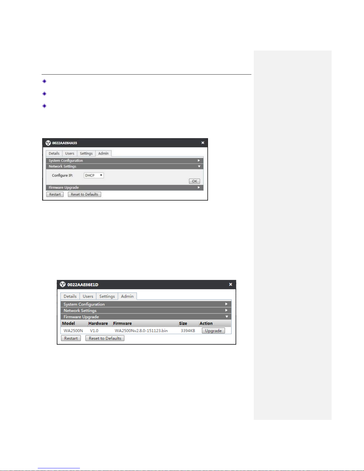
2) Network Settings
Set the way to obtain the IP address of AP, including DHCP (dynamic IP) or Static IP.
Figure 5-12 Network Settings
3) Firmware Upgrade
In the firmware upgrade interface, you can view the information about the currently running
version, or update the firmware. First, download the latest firmware from the UTT website, and
then click Upgrade for system upgrading.
Figure 5-13 Firmware Upgrade
Page 43
UTT Technologies Users Tab
http://www.uttglobal.com Page 38
Chapter 6. Users Tab
On the Users page, the administrator can view all the wireless clients in the intranet. Click
Connected, Disconnected, and Blacklist to respectively manage the clients in different status.
6.1 Connected
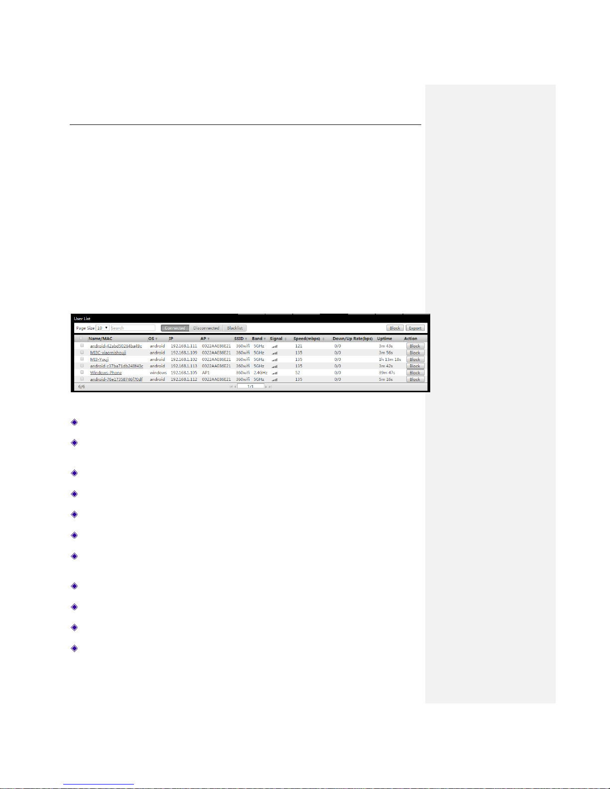
In the Users > Connected page, click the Export button on the top right corner to export the list
and detailed information of online wireless clients. Select multiple wireless clients, and click the
Block button on the top right corner, to join the wireless clients into the blacklist.
Figure 6-1 Connected User List
Name/MAC: Displays the name/MAC address of wireless clients.
OS: Displays the operating system used by wireless clients. Such as Windows, IOS, Android,
etc.
IP: Displays IP address of the wireless client.
AP: Displays the name/MAC address of the AP accessed by the wireless client.
SSID: Displays the name of the wireless network accessed by the wireless client.
Band: Displays the frequency band accessed by the wireless client.
Signal: Displays the strength level of the current wireless signal. Full occupied lattice means
strong signals.
Speed(mbps): Displays the wireless speed rate of wireless clients.
Down/Up rate(bps): Displays the current upload / download rate of the wireless client.
Uptime: Displays the online duration of the wireless client.
Action: Click the Block button to add a wireless client to the blacklist.
Page 44
UTT Technologies Users Tab
http://www.uttglobal.com Page 39
6.2 Disconnected
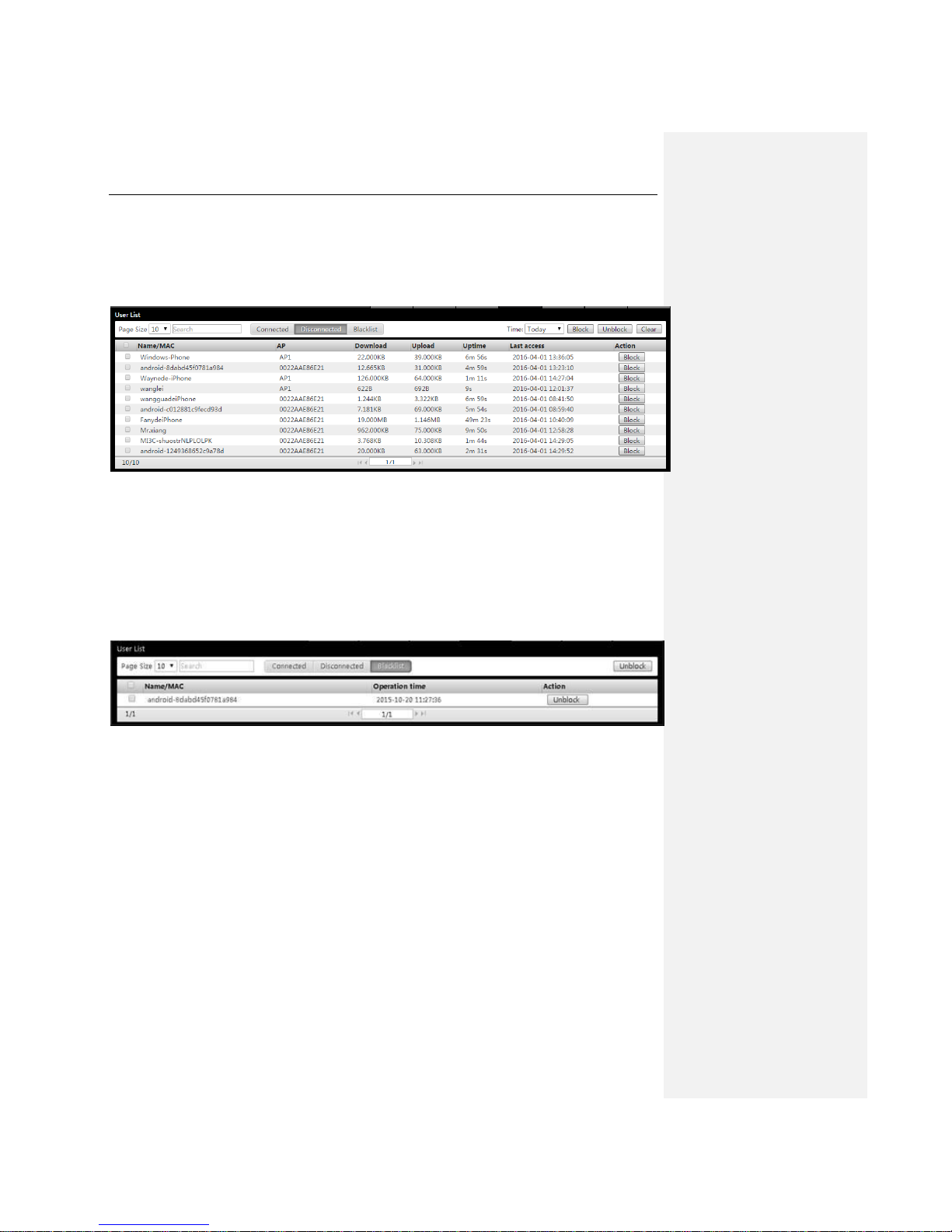
Under this page, you can view the MAC address, access points, download/upload, online time and
last access time of offline wireless clients, or add the offline wireless clients into the blacklist.
Figure 6-2 Disconnected User List
6.3 Blacklist
Under this page, you can view such information as the Name/MAC Address of the blacklist user
and the time of being pulled into the blacklist or remove the client from the blacklist. The blacklist is
effective for all AP.
Figure 6-3 Blacklist User List
Page 45
UTT Technologies Events Tab
http://www.uttglobal.com Page 40
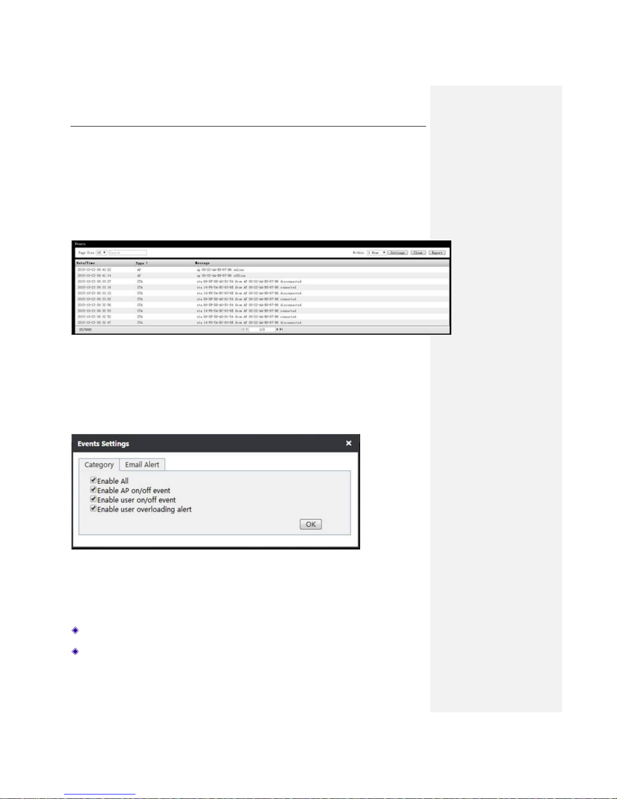
Chapter 7. Events Tab
In the Events page, the system records the AP online/offline logs, wireless client online/offline
logs, wireless client overloading alarm logs and other information. You can display the logs by
category, and delete or export log information.
Figure 7-1 Events Information Interface
1) Setting the events categories
Click Events > Settings > Category to display the interface as shown in the figure below, and
then select the log information categories to be monitored, lastly click OK to save the settings.
Figure 7-2 Events Settings - Category
Enable all: If enabled, all options in the list will be enabled.
Enable AP on/off event: If enabled, the Device will record the online/offline logs of APs.
Page 46
UTT Technologies Events Tab
http://www.uttglobal.com Page 41
Enable user on/off event: If enabled, the Device will record the online/offline logs of wireless
clients.
Enable user overloading alert: If enabled, the Device will record wireless client overloading
logs. It can record more than 20 wireless clients’ connection information.
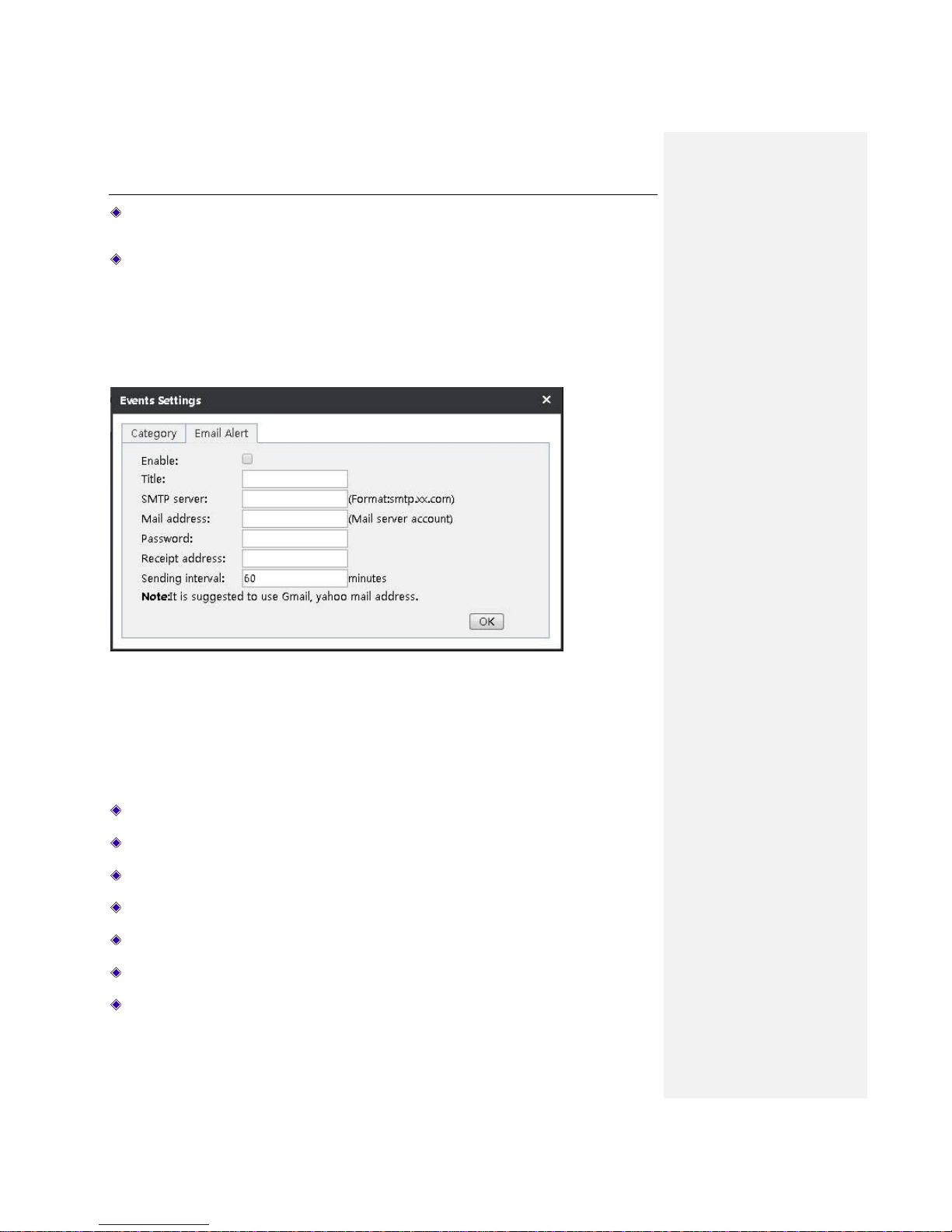
2) Email Alert
Click Events > Settings > Email Alert to show the interface in the figure below, and configure the
title, SMTP server, mail address, password, etc. of the server that sends the monitoring log
information.
Figure 7-3 Log Settings - Monitoring
Enable: Select it to enable this feature.
Title: Specify the subject name for monitoring.
SMTP server: Specify the sending server address.
Mail address: Specify the name of sender’s mailbox, such as 163.com.
Password: Specify the password of sender’s mailbox.
Receipt address: Specify the name of receiver’s mailbox.
Sending interval: Specify the time interval for sending log information.
Page 47

UTT Technologies Events Tab
http://www.uttglobal.com Page 42
Notes: It is recommended to use Gmail, Yahoo mail.
Page 48
UTT Technologies Settings Tab
http://www.uttglobal.com Page 43
Chapter 8. Settings Tab
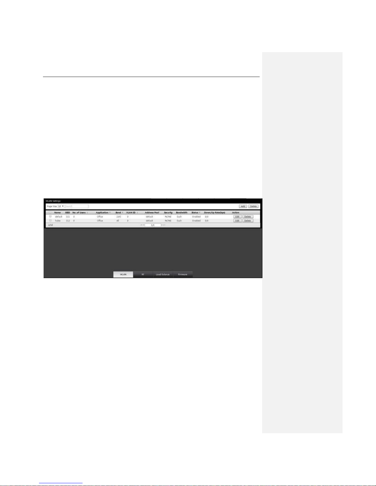
This chapter describes how to configure WLAN, radio frequency template, load balancing,
firmware version, etc. on the AC, and these configurations can be distributed to the AP as a
template.
8.1 WLAN
In the WLAN Settings page, the list of configured WLANs has been displayed. The parameters of
each WLAN in the list can be modified. The configured WLAN are distributed by AP for the
wireless clients to access. Also, you can add or delete a WLAN.
Figure 8-1 Setting Interface
Click the Edit button on the right side of the WLAN to modify the parameters of the WLAN. Click
Delete on the right side of the WLAN to delete the WLAN.
Click Add on the top right corner of the WLAN page to add a WLAN. A dialog box pops up as
shown in Figure 8-2. You can respectively set RF, VLAN, security, QoS. Below is a detailed
description of the meaning of the parameters on the adding WLAN interface.
Page 49
UTT Technologies Settings Tab
http://www.uttglobal.com Page 44
8.1.1 RF
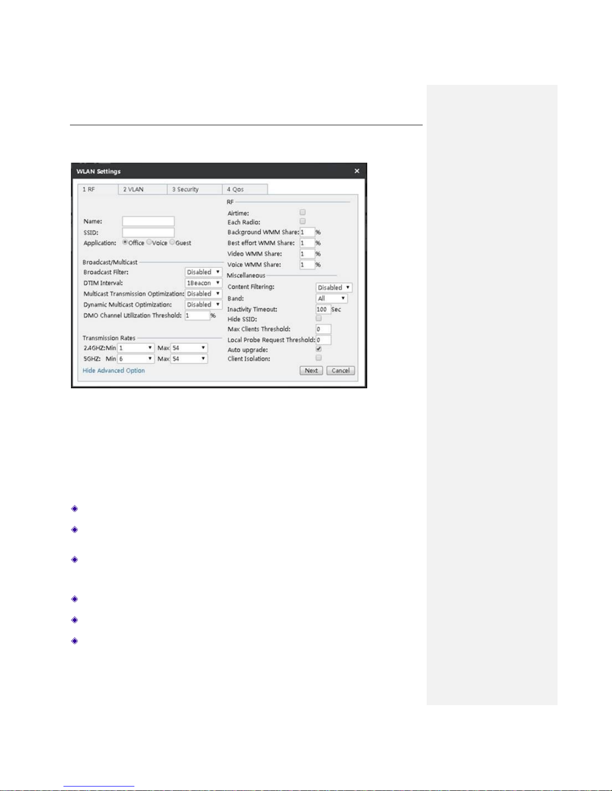
Figure 8-2 WLAN Settings
Name: Specify the name of the WLAN.
SSID: The SSID (Service Set Identification) is also known as the wireless network name,
which is used to uniquely identify a wireless network. It is case sensitive.
Application: The available options are Office (general use), Voice(VoIP or other voice
applications), and Guest(temporary visitors from outside). The access levels of them ranking
from high to low are as follows: Office, Voice, Guest.
Broadcast Filter: Select the way to filter broadcast packets.
DTIM Interval: Select the number of beacon intervals, ranging from 1 and 10 beacons.
Multicast Transmission Optimization: Select to enable/disable optimization of multicast
transmission.
Page 50

UTT Technologies Settings Tab
http://www.uttglobal.com Page 45
Dynamic Multicast Optimization: Select to enable/disable optimal dynamic multicast
transmission.
DMO Channel Utilization Threshold: The higher the percentage, the higher the priority.
2.4GHz: Able to stably reach the Internet by setting the minimum and maximum transmission
rate of 2.4GHz.
5GHz: Able to stably reach the Internet by setting the minimum and maximum transmission
rate of 5GHz.
Airtime: The interface of wireless protocol.
Each Radio: Select it to enable this feature.
Background WMM Share: Specify the percentage of the background WMM share to ensure
the establishing of a stable connection with network resources and provide a high-quality
connection performance.
Best effort WMM Share: Specify the percentage of the most effective WMM sharing to
ensure establishing a stable connection with network resources and provide a high-quality
connection performance.
Video WMM Share: Specify the percentage of the video WMM sharing to ensure establishing
a stable connection with network resources and provide a high-quality video network
connection performance.
Voice WMM Share: Specify the percentage of the language WMM sharing to ensure
establishing a stable connection with network resources and provide high-quality voice
network connection performance.
Content Filtering: Select Enable to enable this feature.
Band: Select the frequency band that the WLAN supports. The available values are 2.4GHz,
5GHz and ALL.
Inactivity Timeout: The default value is 100 seconds.
Hide SSID: If enabled, connection to this SSID is possible only when the SSID name is
manually entered for searching, or before enabling this feature, you have already connected
to the SSID, so that it can be automatically connected.
Max Clients Threshold: Specify the maximum number of clients connected to the AP. It is
recommended not to exceed 20. 0 means no restriction.
Local Probe Request Threshold: Specify the threshold for local detection.
Auto update: Selected by default. It means the new WLAN will be automatically distributed to
all the online APs. When the number of automatically updated WLAN exceeds 4, the new
WLAN will not be automatically distributed.
Client Isolation: Prevent the mutual visit between the connected terminal devices.
Page 51
UTT Technologies Settings Tab
http://www.uttglobal.com Page 46
8.1.2 VLAN
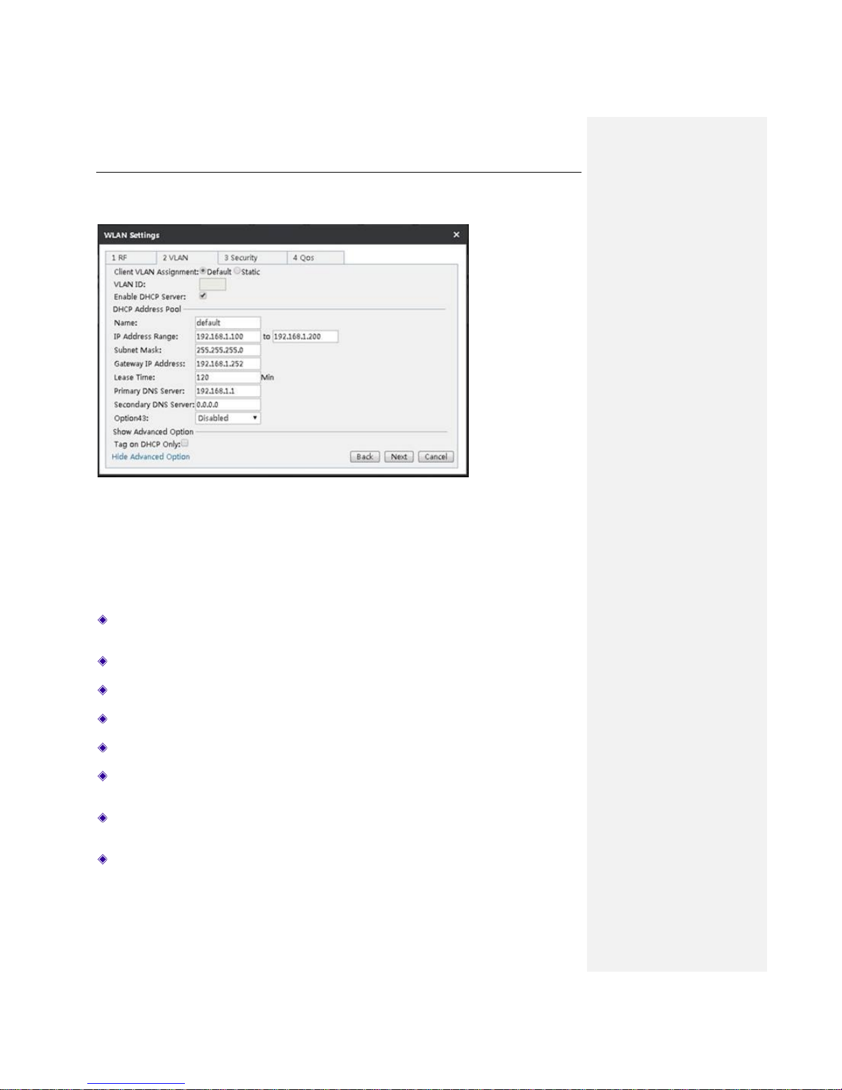
Figure 8-3 VLAN Settings
Client VLAN Assignment: Select Default to use the DHCP address pool in the non-VLAN.
Select Static to use the DHCP address pool you specified in the VLAN.
VLAN ID: Specify the VLAN ID, with the range of value of 1-4094.
Enable DHCP Server: Select it to enable the DHCP server.
Name: Specify the name of custom address pool.
IP Address Range: Specify the range of IP addresses assigned to DHCP clients.
Subnet mask/Gateway IP Address: The subnet mask/gateway addresses assigned by the
DHCP server to the intranet computers, mobile phones and other clients automatically.
Lease Time: The leasing time for the Intranet clients to obtain the IP address assigned by the
Device (Unit: Minutes).
Primary DHCP Server: The primary DNS server IP address assigned by the DHCP server to
the Intranet computers, mobile phones and clients automatically.
Page 52
UTT Technologies Settings Tab
http://www.uttglobal.com Page 47
Secondary DNS Server: The secondary DNS server IP address assigned by the DHCP
server to the Intranet computers, mobile phones and other clients automatically.
Option43: By modifying the variable length fields of option 43 attribute in the DHCP protocol
packets which is used to carry the IP address of AC, AP analyze the AC address to discover
AC. The available options are Disable, HEX Length, ASCII Length, and Customized.
Tag on DHCP only: When the LAN need to be divided into several subnets, and the gateway
does not support VLAN function, you need to select this checkbox. After that, the DHCP
protocol packets will be marked with a tag when clients try to connect AP, and those
non-DHCP protocol packets will not be marked with a tag.
8.1.3 Security
To make access authentication for clients like computers, mobile phones that want to join the
WLAN. Password authentication and free of authentication are now provided. Password
authentication provides three modes, namely WEP, WPA/WPA2 and WPA-PSK/WPA2-PSK. The
following sections will introduce the parameters of them.
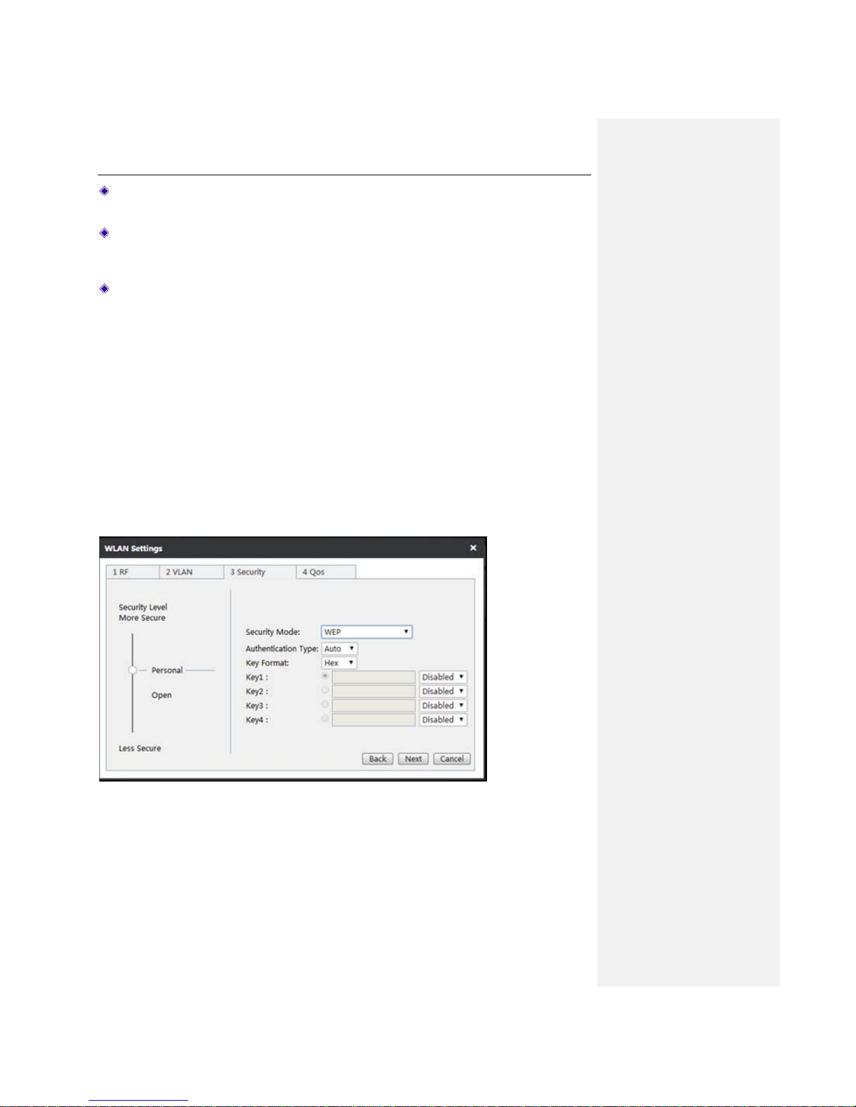
8.1.3.1 WEP
Wired Equivalent Privacy (WEP) is the basic encryption mode which is not as secure as WPA.
Figure 8-4 WEP
Page 53

UTT Technologies Settings Tab
http://www.uttglobal.com Page 48
Authentication Type: Select the authentication type under WEP security mode. The Device
must authenticate a wireless client before the client can join the wireless network. The
available options are Auto, Open System and Shared Key.
Auto: Select to allow the Device automatically choose Open System or Shared key
mode according to the requests of wireless clients.
Open System: At this point, the wireless client host can pass the authentication and be
associated with the wireless devices on the premise of providing no authentication key;
but a correct key must be provided if data transmission is to be made.
Shared Key: At this point, the wireless client host must provide the correct key to passing
the authentication; otherwise, it cannot be associated with the wireless devices, and
cannot perform data transmission.
Key Format: Select the format for entering the WEP keys. The options are Hex and ASCII.
Hex: Select it to enter the WEP keys in hexadecimal format. Hexadecimal digits are a set
of characters that includes numbers 0 through 9 and letters A through F (or a through f).
Hex WEP keys are case insensitive.
ASCII: Select it to enter the WEP keys in ASCII format. ASCII WEP keys are case
sensitive.
Key1~4: Select one of the WEP keys as the default transmit key to transmit data. All keys can
be used to receive data.
Key Type: Select the size of each key, and it also allows you to disable or enable each key.
The options are Disabled, 64-bit and 128-bit. By default, Disabled is selected, which means
the key is of no effect.
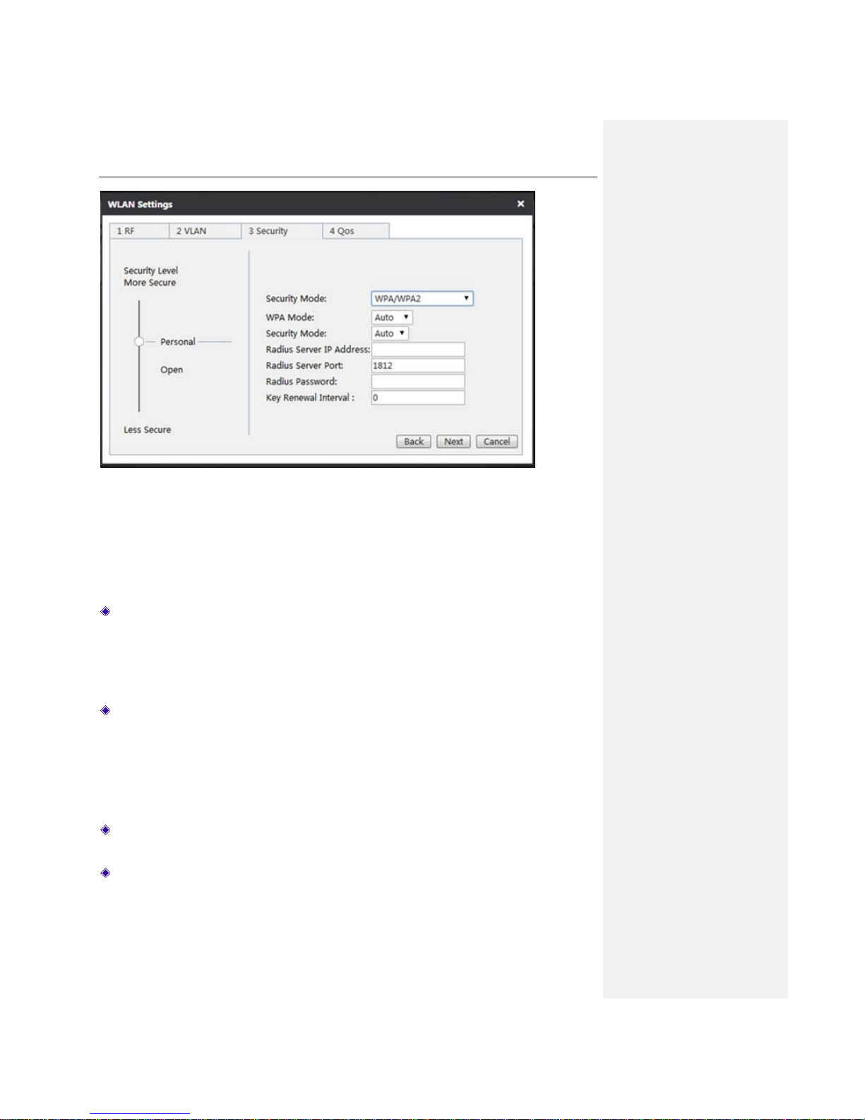
8.1.3.2 WPA/WPA2
Wi-Fi Protected Access (WPA ) and Wi-Fi Protected Access II (WPA2) are two security protocols
and security certification programs to secure wireless computer networks. In WPA/WPA2 mode,
the Device uses an external RADIUS server to authenticate wireless clients.
Page 54
UTT Technologies Settings Tab
http://www.uttglobal.com Page 49
Figure 8-5 WPA/WPA2
WPA Mode: Select the WPA mode you want to use.
Auto: If selected, the Device can automatically choose WPA or WPA2 security mode
according to the requests of wireless clients.
WPA: If selected, the Device will use the security mode of WPA.
WPA2: If selected, the Device will use the security mode of WPA2.
Encryption Method: It is the security algorithm used to encrypt wireless data, with the options
like Auto, TKIP and AES.
Auto: If selected, the Device will automatically choose encryption algorithms according to
needs.
TKIP: If selected, all wireless data will use TKIP as the encryption algorithm.
AES: If selected, all wireless data will use AES as the encryption algorithm.
Radius Server IP Address: Specify the IP address of the RADIUS server, which is used to
authenticate wireless clients.
Radius Server Port: The service port number used by the Radius server for authenticating
wireless hosts. The valid range is 1 to 65535, and the default value is 1812.
Page 55
UTT Technologies Settings Tab
http://www.uttglobal.com Page 50
Radius Password: Specify the password used for authentication between the Device and
RADIUS server.
Key Renewal Interval: Specify the frequency (in seconds) the WPA group key changes.
Value range is 60 ~ 86400 seconds. The default value is 3600 seconds. It means no update
when the value is 0.
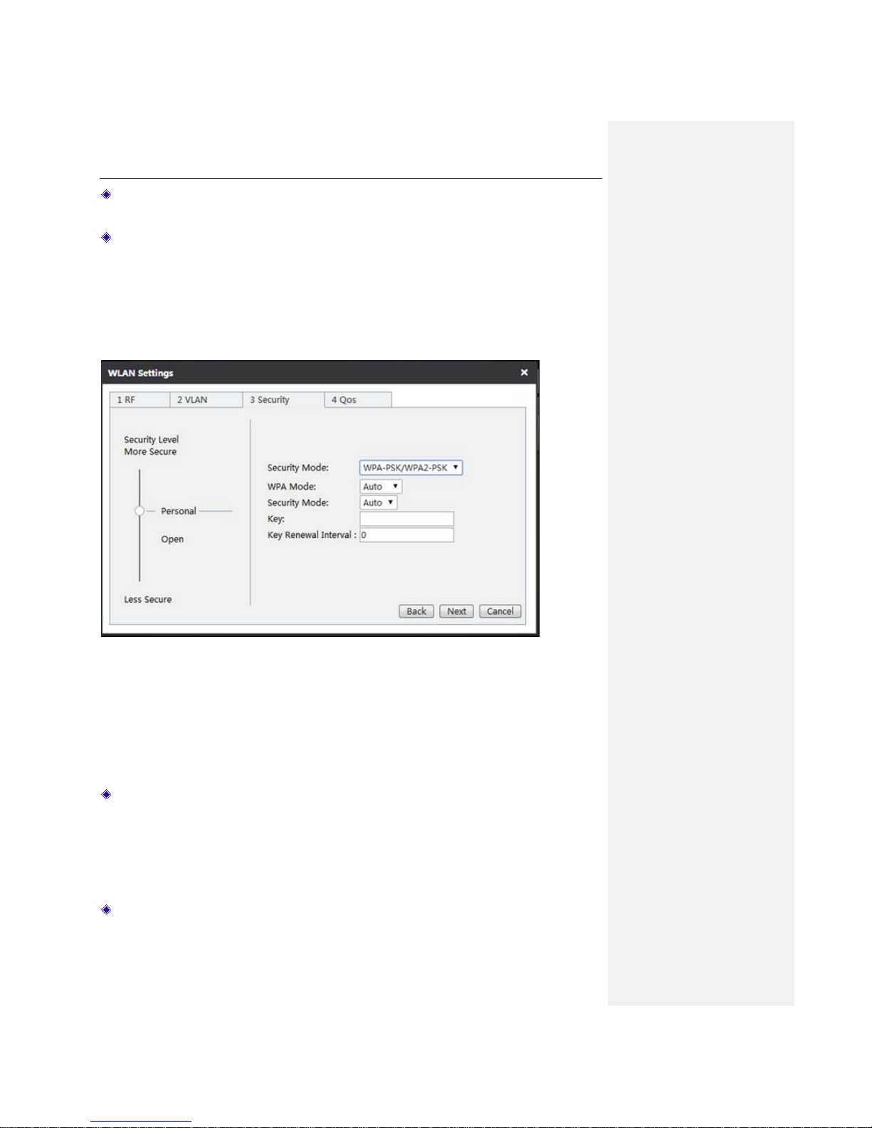
8.1.3.3 WPA-PSK/WPA2-PSK
This mode intends for the wireless network that doesn’t have a RADIUS server. In this mode, the
Device uses the pre-shared key that is manually entered to generate encryption keys.
Figure 8-6 WPA-PSK/WPA2-PSK
WPA Mode: Specify the WPA mode the Device will use:
Auto: If selected, the Device can automatically choose WPA-PSK or WPA2-PSK security
mode according to the requests of wireless clients.
WPA: If selected, the Device will use the security mode of WPA-PSK.
WPA2: If selected, the Device will use the security mode of WPA2-PSK.
Encryption Method: Specify the security algorithm used to encrypt wireless data, with the
options like Auto, TKIP and AES.
Page 56
UTT Technologies Settings Tab
http://www.uttglobal.com Page 51
Auto: If selected, the Device will automatically choose encryption algorithms according to
needs.
TKIP: If selected, all wireless data will use TKIP as the encryption algorithm.
AES: If selected, all wireless data will use AES as the encryption algorithm.
Key: The preset initialization key, with the value of 8 ~ 63 characters.
Key Renewal Interval: Specify the frequency (in seconds) the WPA group key changes.
Value range is 60 ~ 86400 seconds. The default value is 3600 seconds, which means no
update when the value is 0.
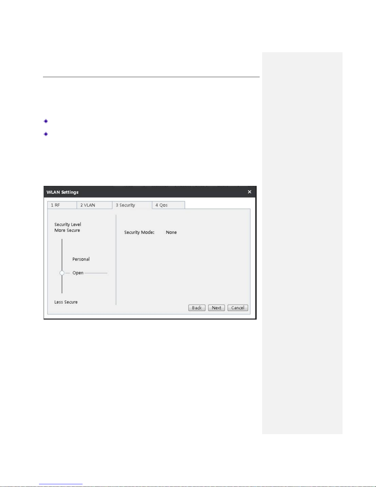
8.1.3.4 None
In the None security mode, the client can access the network without using any security
authentication.
Figure 8-7 None
Page 57
UTT Technologies Settings Tab
http://www.uttglobal.com Page 52
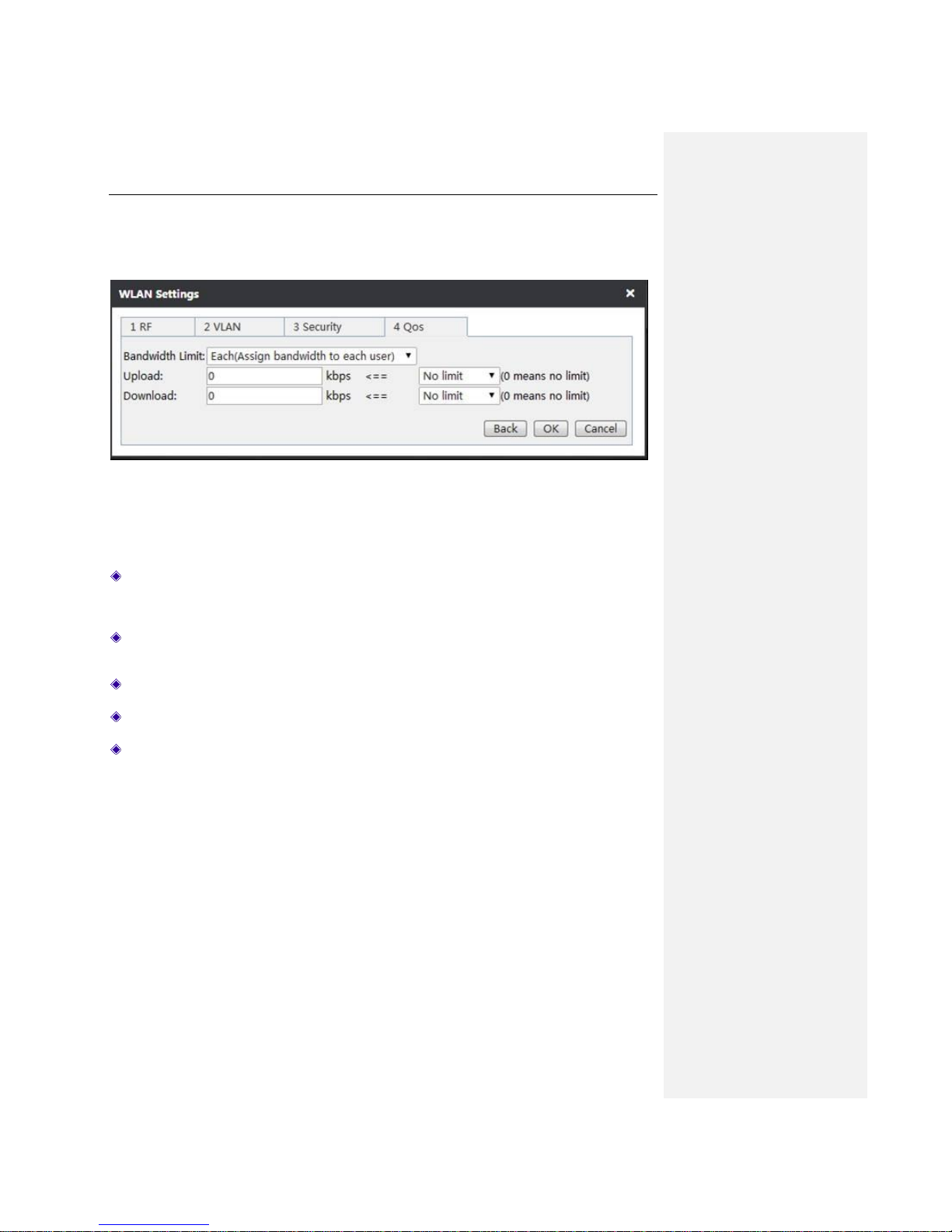
8.1.4 QoS
To set the speed limit for the wireless clients like computers, mobile phones that join the WLAN.
Figure 8-8 Broadband Restrictions
Bandwidth Limit: The available options are Each and Share; Each means each IP address
in this range is assigned with the configured bandwidth; Share means IP addresses in this
range shares the bandwidth.
Upload/Download: Specify the upload speed limit and download speed limit. 0 means no
limitation.
Back: Click to return to the Security interface.
OK: Click to finish configuration.
Cancel: Click to cancel the configuration.
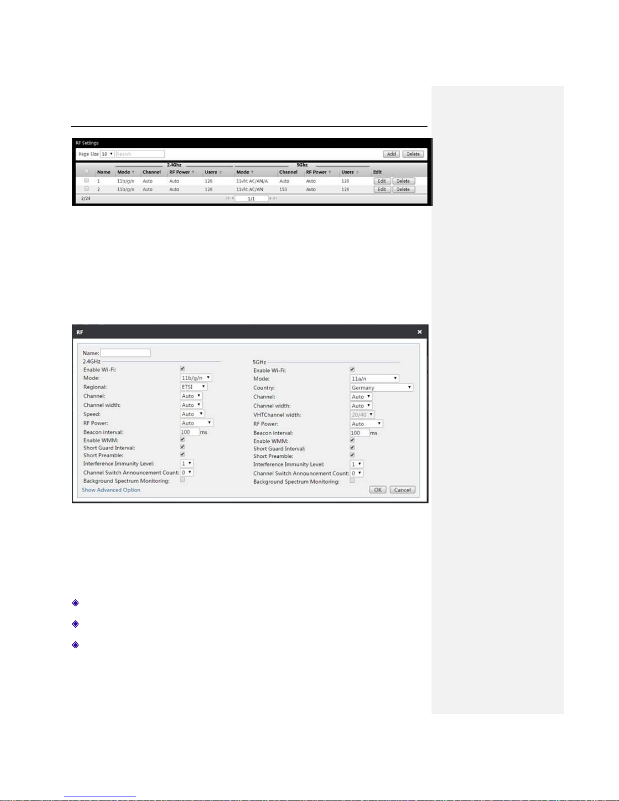
8.2 RF
Set the RF (radio frequency) template for AP to distribute wireless RF parameters. Note: The radio
frequency templates can only be distributed to APs in batch.
The radio frequency template page shows the list of radio frequency templates, in which all the
parameters can be modified. The radio frequency templates can also be deleted or added.
Page 58
UTT Technologies Settings Tab
http://www.uttglobal.com Page 53
Figure 8-9 RF template interface
Click Edit on the right side of the radio frequency template to modify the parameters of the radio
frequency template. Click Delete on the right side of the radio frequency template to delete the
radio frequency template.
In the Settings > RF page, click Add to open up a dialog box as shown in the figure below, and
then set the parameters, lastly click OK to finish the setting. Below is a detailed description of the
meaning of the parameters of the interfaces in adding radio frequency templates.
Figure 8-10 Radio frequency template
Name: Specify the name of the radio frequency template.
Enable Wi-Fi: Select it to enable the wireless function of 2.4 GHz or 5 GHz.
Mode: Select the wireless working mode of AP.
Page 59

UTT Technologies Settings Tab
http://www.uttglobal.com Page 54
Regional: Select the correct region in which the Device lies from the drop-down list. Different
regions will use different channels.
Channel: Select the frequency bands in which the wireless network works; it provides
automatic options, which means that the Device can automatically select the optimal
frequency band. The wireless devices in the same frequency band will interfere with each
other. If there are multiple wireless devices around the AP, please select a frequency band
different from that of other wireless devices when setting the channel.
Channel width: Select the bandwidth of corresponding channels.
Speed: Select the wireless transmission rate.
RF power: Select the wireless transmission power.
Beacon interval: AP will send Beacon frames to the network regularly, and synchronize with
the network. Beacon interval is the periodic time interval for sending Beacon frames. Its value
range is 20~999 milliseconds.
Enable WMM: Select it to enable the WMM function.
Short Guard Interval: Select it to enable this function.
Short Preamble: If selected, it will use Short Preamble. Short Preamble can improve the
utilization of wireless channel to realize high priority transmission bandwidth. If not selected, it
will use long preamble. Which can ensure compatibilities with some old 802.11b devices that
require the long preamble, but it will slightly reduce throughput at high data rate.
Interference Immunity Level: Select the level of interference immunity, with a range of 1 to 5.
Channel Switch Announcement Count: Select the number of channel switching notices,
ranging 1-9.
Background Spectrum Monitoring: Select to enable this function.
Advanced options:
Band Steering Mode: Includes four modes, Disabled, Prefer 5GHZ, Focus 5GHZ and
Balance bands.
Prefer 5GHz: If selected, the Device will guide the STA supporting dual-band frequency
to connect to AP first via 5GHz.
Focus 5GHz: If selected, for STA that supports dual-band frequency, STA is allowed to
connect to AP via 5GHz only.
Balance bands: If selected, the Device will guide STA to connected to WLAN of 2.4 GHz
or 5 GHz in a balanced way.
No. of 2.4G User: Specify the maximum number of wireless clients in the 2.4GHz band for
one AP.
No. of 5G User: Specify the maximum number of wireless clients in the 5GHz band for one
AP.
Page 60
UTT Technologies Settings Tab
http://www.uttglobal.com Page 55
8.3 Load Balance
When the covering area overlaps between the APs, these APs can be set up for load balancing,
and by setting this parameter, the wireless clients in the overlapped area can be connected to the
APs in a load-balancing way, so that the quality of network service can be improved. The load
balance groups can be modified, deleted, added, etc. You can add up to 32 load balance groups.
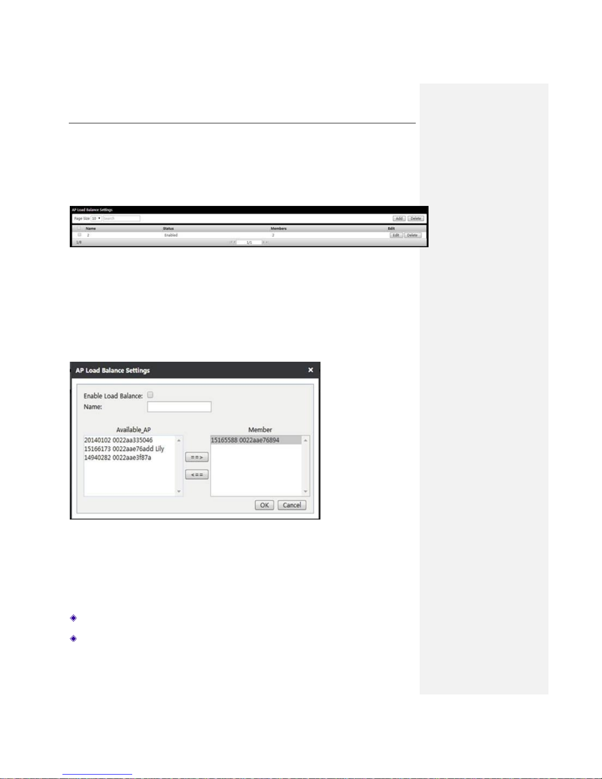
Figure 8-11 Load Balance
Modify load balancing group: Click Edit to modify the current load balancing configuration.
Delete load balancing group: Click Delete on the right end of the corresponding load
balancing group.
Add load balancing group: Click Add to open up a dialogue as shown in the following figure.
You can add APs into the load balancing group.
Figure 8-12 Load Balance Settings
Enable Load Balance: Select it to enable the load balancing function.
Name: Specify the name of this load balance group.
Page 61
UTT Technologies Settings Tab
http://www.uttglobal.com Page 56
Available_AP: Displays the basic information of the current AP.
Member: Displays the basic information of the APs that have enabled the load balancing
function. (A load balancing group's configuration range is 2 ~ 5 sets of AP.)
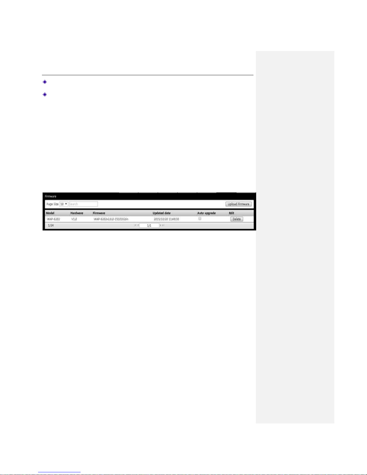
8.4 Firmware
You can check the firmware information of the current AP (which is stored in the memory) by
viewing the Firmware list, or upload the latest version of firmware of the AP. If the corresponding
AP model of the uploaded firmware is the same the one that is stored in the memory, the new
firmware will cover the old version one.
After checking Auto upgrade, all the APs in this model will be automatically upgraded in the
restarting of the APs. Note: Only when the version of the uploaded firmware is higher than that of
the current AP, the system will automatically upgrade. If you want to upgrade a single AP or
several specified APs, please upgrade the corresponding AP under the Access Point menu.
Figure 8-13 Software Management
8.5 Example of APs’ centralized management
Requirements:
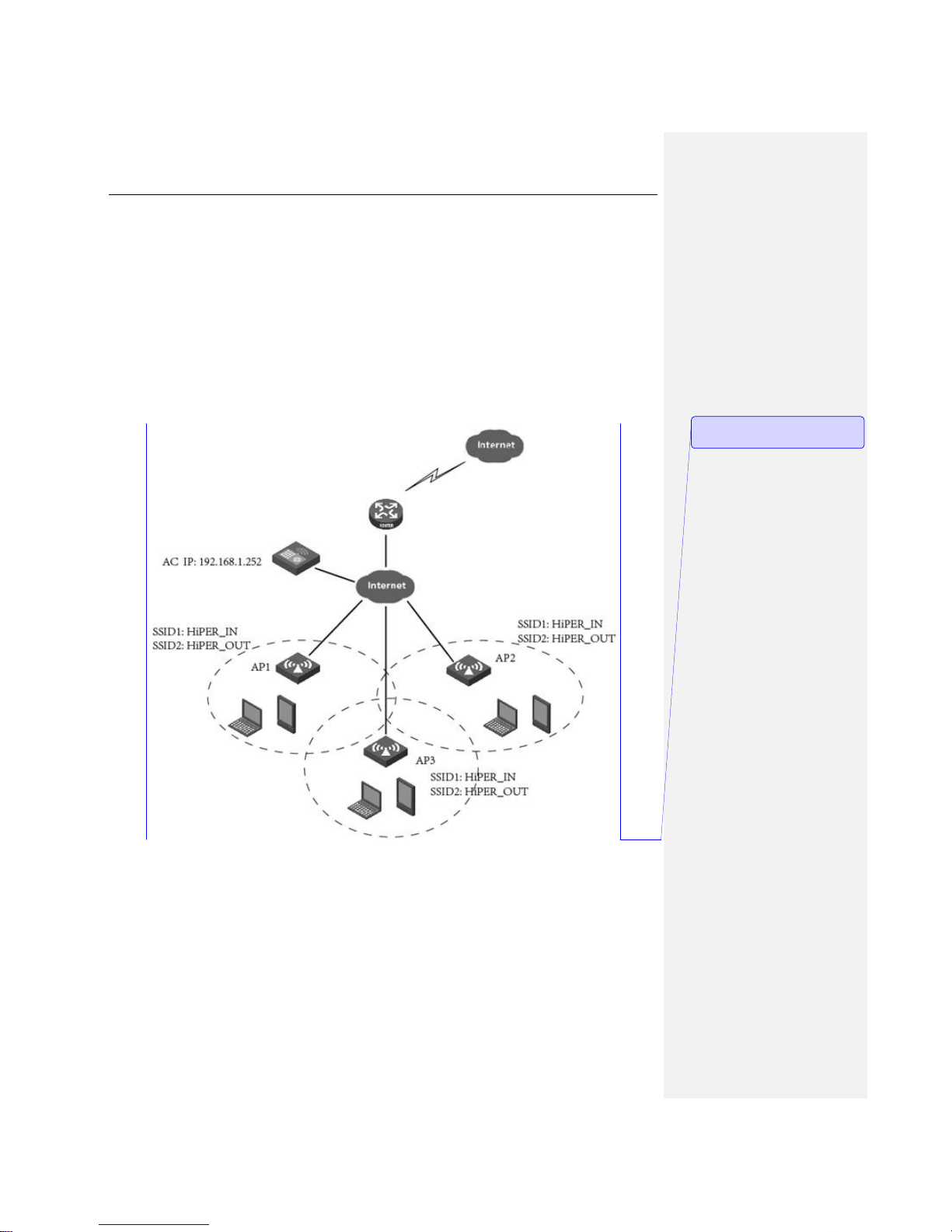
A small business bought three sets of APs and wants to set up a wireless network within the
company. The following requirements and must be met:
1) The wireless network can cover the whole office area of the company.
2) With this wireless network, the company employees can use wireless terminals to access to the
enterprise's internal resources and the Internet, while guests can only use the wireless terminals
to access the Internet, not the enterprise’s internal resources.
3) The number of clients on all three APs should be as even as possible.
Analysis:
Page 62
UTT Technologies Settings Tab
http://www.uttglobal.com Page 57
1) In order to cover the whole office area with wireless network, install the three APs in the
corresponding office area reasonably, make sure they can realize a seamless connection through
the two-layer roaming.
2) Create two WLANs on the AC, one for the company employees, and the other for guests.
Joining all APs into these two WLANs (to achieve 2-layer roaming of wireless network). The
corresponding personnel will be able to access the network in any position of the office area by
connecting to the corresponding SSID.
3) Add the three APs into the same load balancing group on AC to realize load balancing between
the APs.
4) Prevent guests from accessing the internal resources by configuring a strategy on AC.
Figure 8-14 AP Centralized Management Configuration Instance
Configuration steps:
1) Access configuration
Connect the AC in bypass mode to the company network. The upper interface VLAN connected to
the AC here is VLAN10.
2) Interface configuration
批注 [周瑶4]: 图中的 SSID 建议修改
为 Office 和 Guest
Page 63
UTT Technologies Settings Tab
http://www.uttglobal.com Page 58
Log in to AC, configure the LAN port and WAN port of the Device to complete the basic Internet
configuration. Here, the LAN port IP address is 192.168.1.252.
3) WLAN configuration
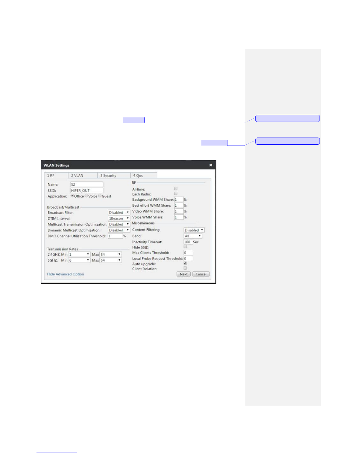
Enter the Settings > WLAN page, to configure two WLANs as default, S2.
The SSID of the default WLAN is set to HiPER_IN, enable SSID broadcasting, the encryption
mode is set to WPA-PSK/WPA2-PSK, the pre-shared key is 1234567890, and the AP
management VLAN range is set to 10.
The configuration of WLAN S2 is shown in the figure below. Its SSID is set to HiPER_OUT, the
SSID broadcasting is enabled, the encryption mode is WPA-PSK/WPA2-PSK, and the AP
management VLAN range is set to 10.
Figure 8-15 WLAN Settings
4) Remote management
批注 [周瑶5]: 建议修改为 Office
批注 [周瑶6]: 建议修改为 Guest
Page 64
UTT Technologies Settings Tab
http://www.uttglobal.com Page 59
After the DHCP server, WLAN, etc. are configured, you can click on top of the page to go to
Access Points page, and remotely manage the three APs.
In the Access Points page, click the AP name > Settings > WLAN Settings, then select the
WLAN whose names are default, S2, lastly click Join WLAN. Please add the other two APs into
these two WLAN in the same way.
5) Load Balance
(1) Enter the Settings > Load Balance page.
(2) Click the Add button, to open the AP Load Balance Settings window.
(3) Select Enable Load Balance.
(4) Input the name of load balancing group, HiPER_NEW.
(5) Add the three APs into the load balancing group.
(6) Click the OK button.
With the above configuration, the enterprise employees can access the network through
HiPER_IN; the guests can access the network through HiPER_OUT.
8.6 Example of APs’ centralized management (Third
layer management)
1) Requirements:
AP Resolves the AC address through option 43, and discover AC.
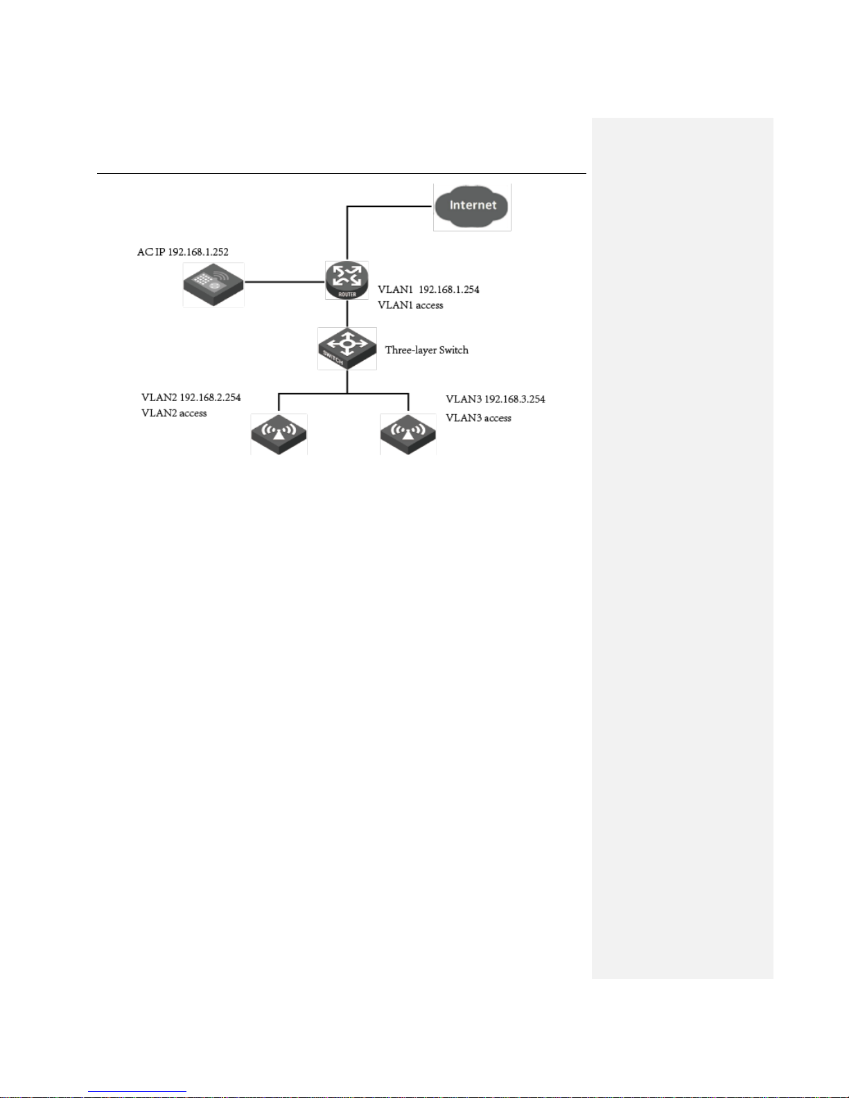
There are three VLANs configured on the 3-layer switch, VLAN1, VLAN2 and VLAN3. AP1 is
connected to the access interface on which VLAN2 is assigned. The IP address of VLAN2’s virtual
interface is 192.168.2.254. AP2 is connected to the access interface on which VLAN3 is assigned.
The IP address of VLAN3’s virtual interface is 192.168.3.254. The LAN IP address of AC is
192.168.1.252. The IP address of VLAN1’s virtual interface is 192.168.1.254.
The address pool of each VLAN is created corresponding to its IP address, and its option 43 set to
the IP address of AC in the format of dotted decimal 192.168.1.252, or in dotted hexadecimal
0104C0A801FC, in which 01 represents fixed identifier while 04 represents the character length of
4 bytes. Configure option 60 on each VLAN to “UTT” in the format of ASCII.
2) Environment topology
批注 [周瑶7]: 最好把 Hiper 都换成
UTT
Page 65
UTT Technologies Settings Tab
http://www.uttglobal.com Page 60
Figure 8-16 Three-layer Environment
3) Operation procedures
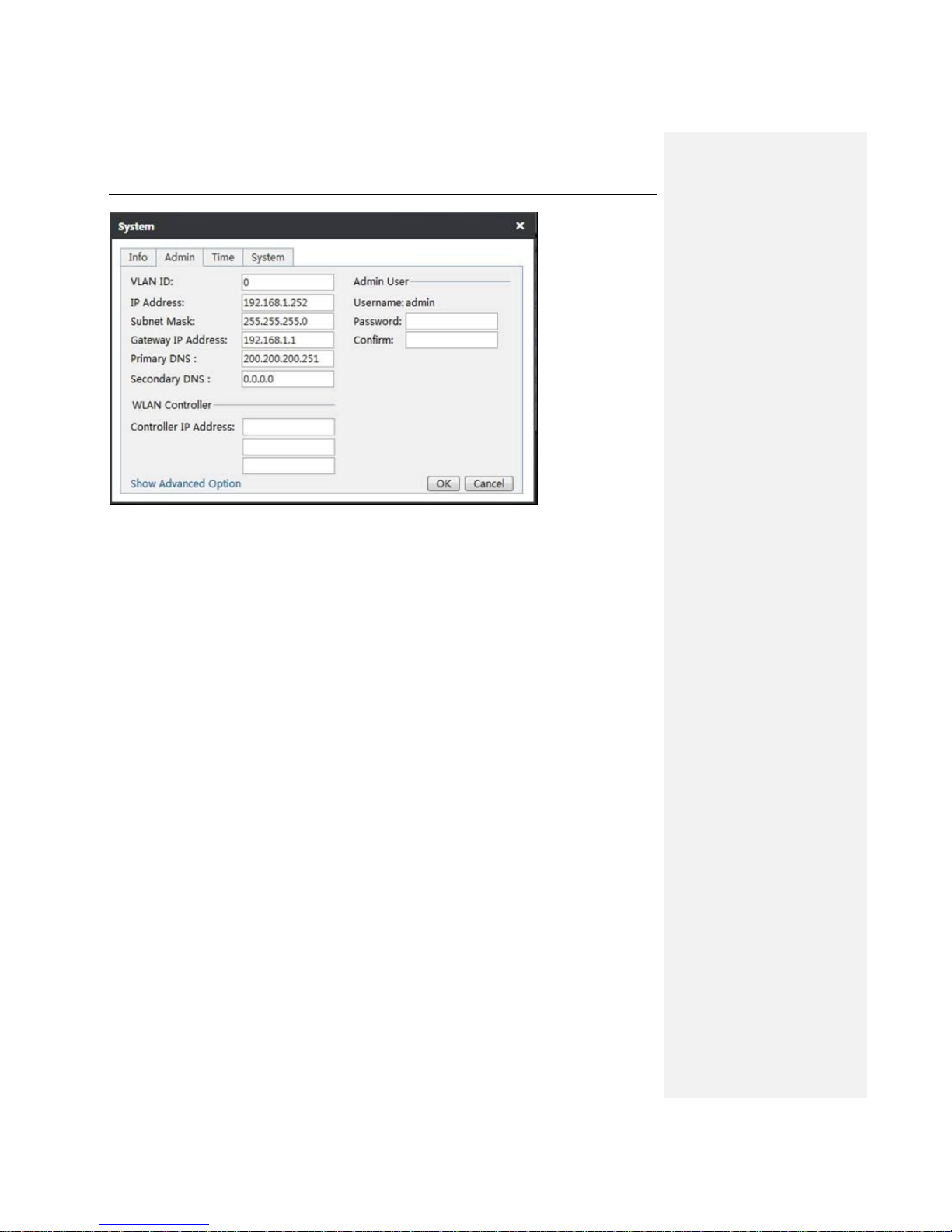
(1) Click System > Admin, and configure the TCP/IP address of AC in the figure below.
Page 66
UTT Technologies Settings Tab
http://www.uttglobal.com Page 61
Figure 8-17 AC IP Address Configuration
(2) Input telnet 192.168.1.254 on the command line interface on the computer to access a switch,
create a VLAN virtual interface, divide the VLAN, configure the DHCP pool corresponding to the
VLAN, configure option 43 and option 60 within the corresponding DHCP pool. The detailed
configuration is as follows:
no service password-encryption
hostname ST3528F
sysLocation China
authentication line console login local
service DHCP
ip dhcp excluded-address 192.168.2.1
ip dhcp excluded-address 192.168.2.254
ip dhcp excluded-address 192.168.3.1
Page 67

UTT Technologies Settings Tab
http://www.uttglobal.com Page 62
ip dhcp excluded-address 192.168.3.254
ip dhcp pool vlan2
network-address 192.168.2.0 255.255.255.0
lease 0 2 0
default-router 192.168.2.254
dns-server 200.200.200.251 8.8.8.8
option 43 ip 192.168.1.252
option 60 ascii UTT.AP
ip dhcp pool vlan3
network-address 192.168.3.0 255.255.255.0
lease 0 2 0
default-router 192.168.3.254
dns-server 200.200.200.251 8.8.8.8
option 43 hex 0104C0A801FC
option 60 ascii UTT.AP
vlan 1-3
Interface Ethernet1/0/7
switchport access vlan 2
Interface Ethernet1/0/8
switchport access vlan 2
Interface Ethernet1/0/9
switchport access vlan 3
Interface Ethernet1/0/10
switchport access vlan 3
interface Vlan1
Page 68
UTT Technologies Settings Tab
http://www.uttglobal.com Page 63
ip address 192.168.1.254 255.255.255.0
interface Vlan2
ip address 192.168.2.254 255.255.255.0
interface Vlan3
ip address 192.168.3.254 255.255.255.0
ip route 0.0.0.0/0 192.168.1.252
no login
end
(3) Open the AC management web page to check if two APs are discovered, and the IP address of
the APs should be 192.168.2.x and 192.168.3.x.
(4) Open WLAN page of AC, create a new WLAN to be distributed to the two APs, and observe if
they can take effect.
Figure 8-18 AP Management List
Page 69
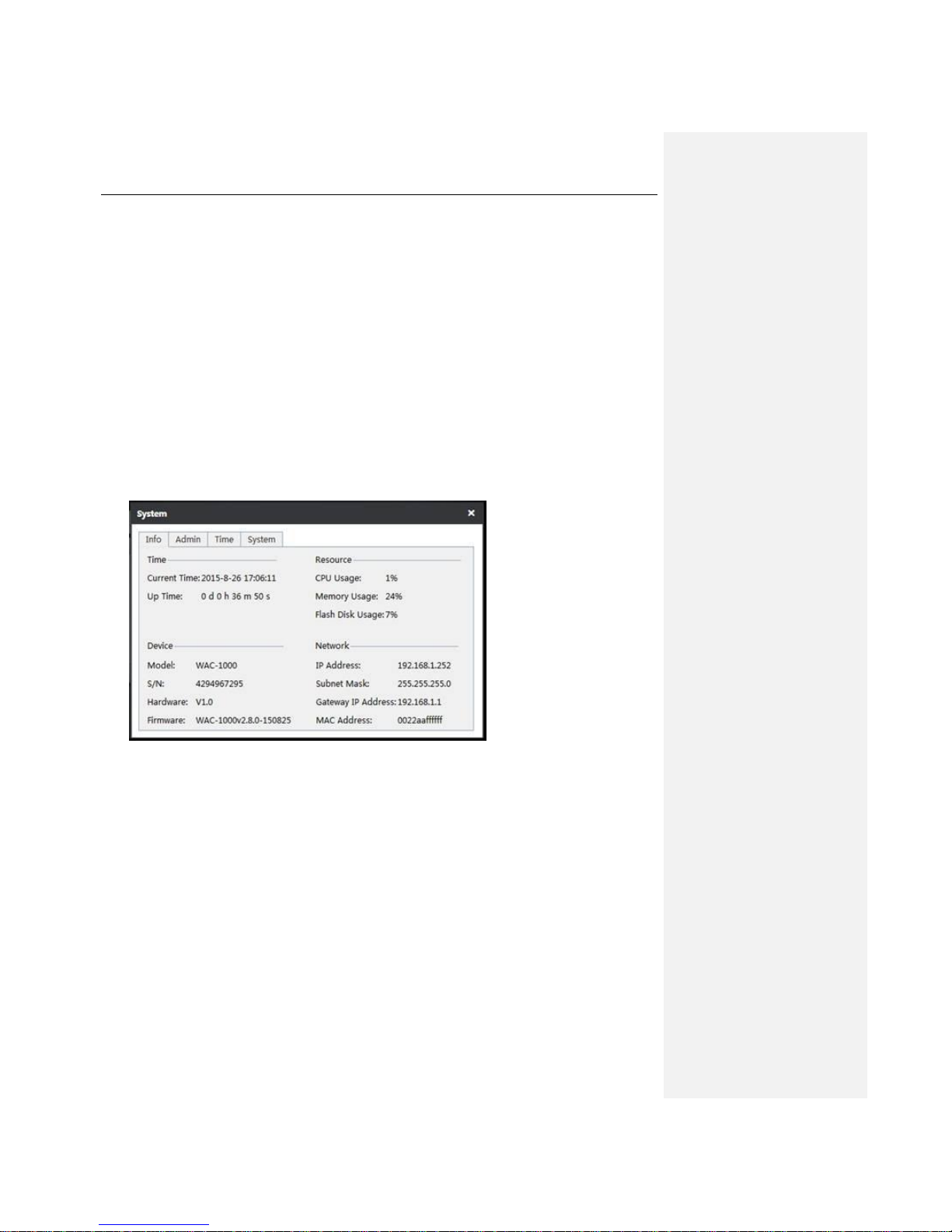
UTT Technologies System Tab
http://www.uttglobal.com Page 64
Chapter 9. System Tab
This chapter mainly describes the way to set time, backup the configuration, import the configuration
files, upgrade firmware, etc.
9.1 Information
On the System > Information page, the administrator can view the system information and find
existing/potential problems in the network by observing the system information, thus improving the
network performance and enhancing network security. The details of the Info interface are shown
below.
Figure 9-1 System Information
9.2 Admin
On this page, you can modify parameters like the IP address of the AC and user account. Please
refer to the following figure for more details.
Page 70
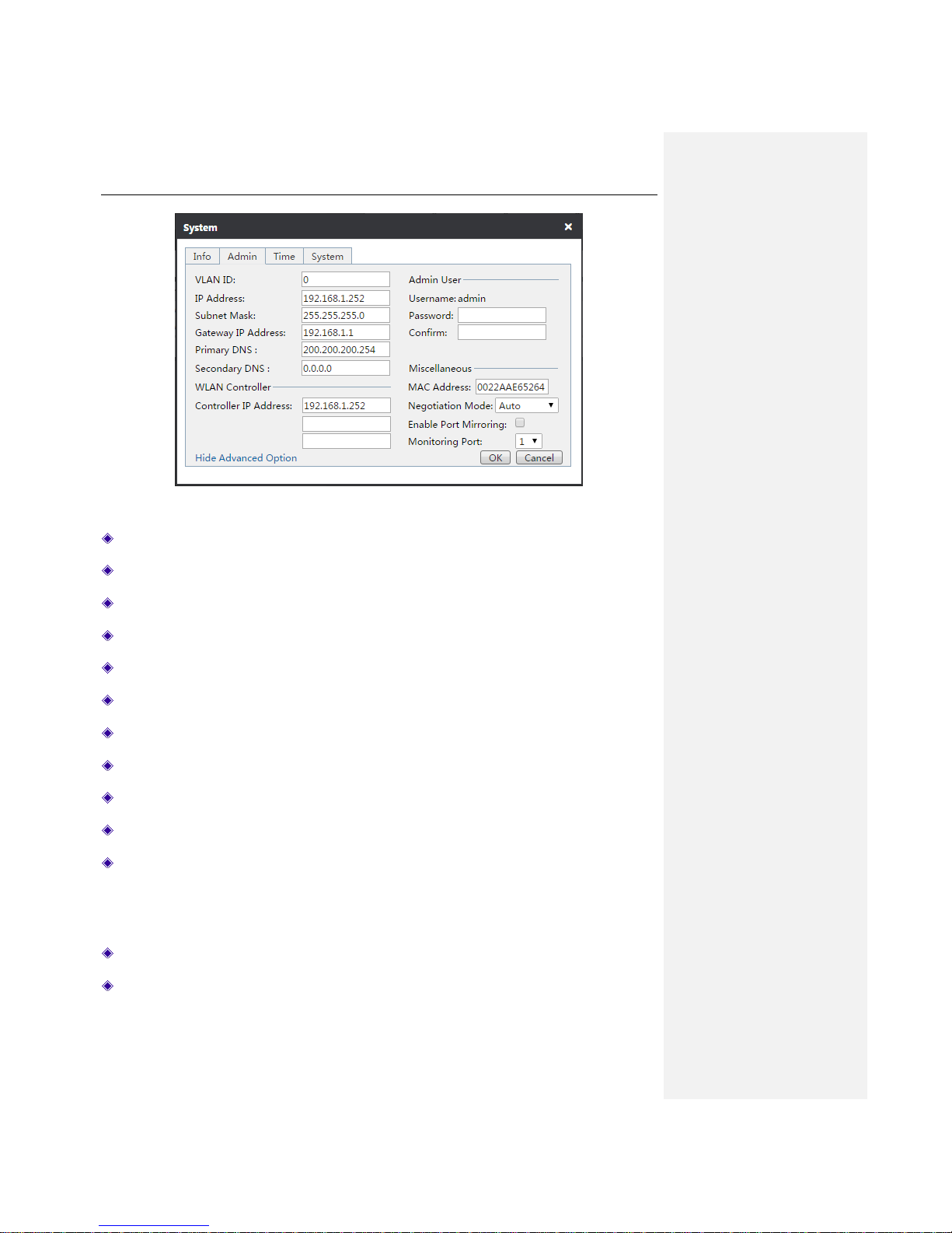
UTT Technologies System Tab
http://www.uttglobal.com Page 65
Figure 9-2 Systems Management
VLAN ID: Specify the VLAN ID which ranges between 0-4094.
IP Address: Specify the IP address of AC.
Subnet mask: Specify the subnet mask.
Gateway IP Address: Specify the gateway address.
Primary DNS: Specify the IP address of the primary DNS server.
Secondary DNS: Specify the IP address of the secondary DNS server.
Controller IP Address: Specify the IP address of wireless controllers.
Password: Specify the Administrator password.
Confirm: Enter the password again.
MAC Address: The MAC address of the Device. It is suggested keep it as default.
Negotiation Mode: Specify the duplex mode and rate for interfaces. Options are: Auto
(adaptive), 10M-FD (10M full duplex), 10M-HD (10M half duplex), 100M-FD (100M full duplex),
100M-HD (100M half duplex). The default option is Auto, which is usually recommended to be
kept as default. If there are any compatibility issues, or the device used does not support
automatic consultation function, the Ethernet negotiation mode can be changed here.
Enable Port Mirroring: Select it to enable this feature.
Monitoring Port: Any one of ports 1 ~ 5 can be selected, and the monitoring port is LAN1 by
default.
Page 71
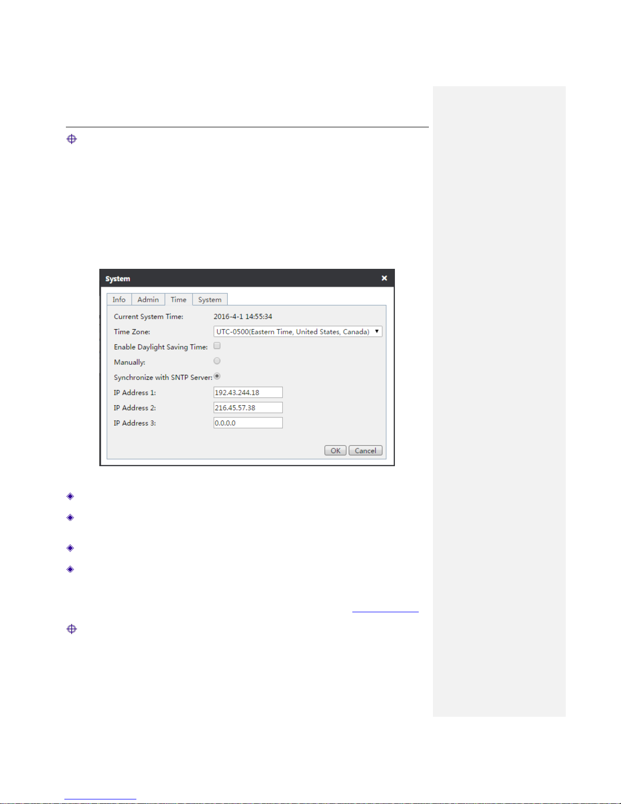
UTT Technologies System Tab
http://www.uttglobal.com Page 66
Notes: After modifying the IP address of LAN port, you must use the new IP address to log into
the Device.
9.3 Time
In order to guarantee that the functions of the Device related to time work normally, the clock of the
Device needs to be accurately set to make it synchronize with the local standard time. The Device
provides two ways of system time setting, Manually and Synchronize with SNTP Server. It is
recommended to use Synchronize with SNTP Server, then the Device will automatically get the
standard time from the Internet.
Figure 9-3 Time
Current System Time: Displays the current date and time (format: Y-M-D, H:M:S).
Time Zone: Select the international time zone in which the Device resides. The correct time
zone configuration can guaranty proper operation of the time synchronization function.
Manually: Click to manually set the current date and time (format: Y-M-D, H:M:S).
Synchronize with SNTP Server: After using the network time synchronization function to set
up the right NTP server and that the Device is connected to the Internet, it will automatically
synchronize the time with the set NTP server. The two NTP server addresses preset by the
system by default are 111.43.244.18, 216.45.57.38, which generally requires no change. If you
need to know more about the NTP knowledge and the server, please visit http://www.ntp.org.
Notes: It is recommended to set the Device clock to synchronize with SNTP Server. Only when
the system time is properly configured can the functions related to time work normally, such as
firewall!
Page 72
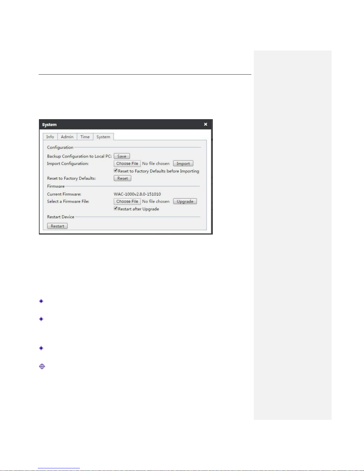
UTT Technologies System Tab
http://www.uttglobal.com Page 67
9.4 System
In the System > System, you can backup the AC configuration files to the local PC, import a new
configuration file to the system, restore the factory configuration and view the information of the
currently running firmware.
Figure 9-4 System Configuration
Backup Configuration to Local PC: Click the Save button in the above figure to back up
the .xml format configuration file AC to the local PC.
Import Configuration: Click the Choose File button in the above figure, then import the
configuration file from the local PC. If you have selected the Reset to Factory Defaults before
Importing check box, after you click the Import button the Device will be recovered to the
factory configuration before importing the new configuration file.
Reset to Factory Defaults: Click the Reset button in the above figure and restart the Device,
to restore the factory configuration.
Notes:
1) Please do not turn off the Device in the process of loading configuration, in order to avoid
unexpected errors.
Page 73

UTT Technologies System Tab
http://www.uttglobal.com Page 68
2) Recovery of device factory settings will delete all the custom configurations. It is strongly
recommended to back up the configuration file before restoring the factory configuration.
3) Both the default username and password of the Device are admin, and the default LAN port IP
address/subnet mask is 192.168.1.252/ 255.255.255.0.
4) After clicking the Reset button, the Device needs to be rebooted before restoring its factory
settings.
Steps for upgrading the firmware of the AC:
1) Download the latest version of firmware of the same model from the UTT official website. It is
recommended to backup the current configuration of the system before the upgrade.
2) Click the Choose File button in the above figure, and find the latest version of firmware
downloaded on the local computer.
3) After selecting the firmware, click the Upgrade button to upgrade the software on your Device.
Notes:
1) Please select an appropriate version of firmware to upgrade: The version of the downloaded
firmware must be consistent with the hardware version of the current product.
2) It is recommended to backup the current configuration of the system before upgrading.
3) It is strongly recommended to implement the upgrade when the device load is low (users
amount is relatively small).
4) Upgrading device firmware on a regular basis enables the Device to get more functions or to
have a better working performance. Correct firmware upgrading will not change the current
device settings.
5) During the upgrading process, the Device's power supply cannot be shut down, otherwise, it
will cause unpredictable errors and even irreversible damages to the hardware.
6) After the completion of upgrading the firmware, the Device will automatically restart to for the
upgrade to take effect.
Page 74

UTT Technologies System Tab
http://www.uttglobal.com Page 69
Page 75

UTT Technologies FAQ
http://www.uttglobal.com Page 70
Chapter 10. FAQ
A - 1 A device is to be used as a wireless client, but it cannot connect to the wireless
network. Why?
After confirming that the Device is powered on and connected properly, please check the following
configurations of the client device.
1. If the "AP SSID" values set on the wireless client are consistent with the SSID of the AP.
2. The "AP MAC" values set on the wireless client are consistent with the MAC address of the
AP.
3. The security mode and key set on the wireless client are consistent with those on the AP.
4. The AP has already enabled the wireless feature and is properly configured in AP mode.
A - 2 How to restore the Device to the factory settings?
Case I: With the administrator password
Under normal circumstances, you can directly go to the System > System page, click Reset
button, and restart the Device after the reset operation is complete.
Case II: Forgotten the administrator password
If you forget the administrator password, you can use a pin to press and hold the Reset button on
the front panel of the Device for more than 5 seconds when the Device is on, and then release the
button. After that, the Device will restart with factory default settings.
Notes: The reset operation will clear all custom settings on the Device, so do it with caution.
Page 76
UTT Technologies Appendix A List of Common IP
http://www.uttglobal.com Page 71
Appendix A List of Common IP
Protocol
Protocol No.
Full name
IP 0 Internet Protocol
ICMP
1
Internet Protocol Message Protocol
IGMP
2
Internet Group Management
GGP 3 Gateway-Gateway Protocol
IPINIP
4
IP in IP Tunnel Driver
TCP 6 Transmission Control Protocol
EGP 8 Exterior Gateway Protocol
IGP 9 Interior Gateway Protocol
PUP 9 PARC Universal Packet Protocol
UDP
17
User Datagram Protocol
HMP
20
Host Monitoring Protocol
XNS-IDP
22
Xerox NS IDP
RDP
27
Reliable Datagram Protocol
GRE
47
General Routing Encapsulation
ESP
50
Encap Security Payload
AH
51
Authentication Header
RVD
66
MIT Remote Virtual Disk
EIGRP
88
Enhanced Interior Gateway Routing Protocol
OSPF
89
Open Shortest Path First
Page 77

UTT Technologies Appendix B Common service ports
http://www.uttglobal.com Page 72
Appendix B Common service ports
Characters
Enter
ESC
Space
! " # $ % & ’ ( ) * +
,
ASCII
0D
1B
20
21
22
23
24
25
26
27
28
29
2A
2B
2C
Characters
- . / 0 1 2 3 4 5 6 7 8 9 : ;
ASCII
2D
2E
2F
30
31
32
33
34
35
36
37
38
39
3A
3B
Characters
< = > ? @ A B C D E F G H I J
ASCII
3C
3D
3E
3F
40
41
42
43
44
45
46
47
48
49
4A
Characters
K L M N O P Q R S T U V W X Y
ASCII
4B
4C
4D
4E
4F
50
51
52
53
54
55
56
57
58
59
Characters
Z [ \ ] ^ - a b c d e f g h i
ASCII
5A
5B
5C
5D
5E
5F
61
62
63
64
65
66
67
68
69
Characters
j k l m n o p q r s t u v w x
ASCII
6A
6B
6C
6D
6E
6F
70
71
72
73
74
75
76
77
78
Characters
y z { | }
~
ASCII
79
7A
7B
7C
7D
7E
 Loading...