

Page 1

User Manual
SOHO Wireless Router
Page 2

Copyright Notice
Copyright © 2000-2016. Shanghai UTT Technologies Co., Ltd.
All rights reserved.
The information of this publication is protected by copyright. No part of this publication may be
reproduced, transmitted, transcribed, stored in a retrieval system, or translated into any language
without written permission from the copyright holders. The scope of delivery and other details are
subject to change without prior notice.
Trademark
UTT
®
is a registered trademark of Shanghai UTT Technologies Co., Ltd.
Other trademarks and registered trademarks of products mentioned in this publication may be the
properties of their respective owners and are only used for identification purposes.
Version 1.0_201603
Page 3

Table of Contents
About this Manual ........................................................................................................................... 1
0.1 Manual Description ..................................................................................................... 1
0.2 Web UI Style ............................................................................................................... 1
0.3 Document Conventions............................................................................................... 2
0.3.1 Format ................................................................................................................. 2
0.3.2 Icons .................................................................................................................... 2
0.4 Default Factory Settings .............................................................................................. 3
0.5 Contact us .................................................................................................................. 3
Chapter 1. Hardware Installation .................................................................................................. 4
1.1 Panel Description ........................................................................................................ 4
1.2 Installation Guideline .................................................................................................. 5
1.3 Installation Requirements ........................................................................................... 6
1.4 Installation Procedure ................................................................................................. 6
1.5 Connecting the Device ................................................................................................ 6
Chapter 2. Logging to the Device ................................................................................................. 8
2.1 Configuring your computer .......................................................................................... 8
2.2 Logging to the Device ................................................................................................. 9
Chapter 3. Setup Wizard ............................................................................................................ 12
3.1 Running the Setup Wizard ........................................................................................ 12
3.2 Internet ..................................................................................................................... 12
3.2.1 PPPoE ............................................................................................................... 13
3.2.2 Dynamic IP ........................................................................................................ 13
3.2.3 Static IP ............................................................................................................. 14
3.3 Wireless .................................................................................................................... 14
3.3.1 2.4GHz Wireless ................................................................................................ 14
3.3.2 5GHz Wireless ................................................................................................... 15
Chapter 4. Application ................................................................................................................ 17
4.1 DHCP server ............................................................................................................ 17
4.2 DDNS ....................................................................................................................... 18
4.2.1 DDNS Service provided by 3322.org .................................................................. 19
4.2.2 DDNS Service provided by Peanut shells .......................................................... 19
4.2.3 DDNS Service provided by uttcare.com ............................................................. 20
4.2.4 DDNS Service provided by no-ip.com ................................................................ 21
4.2.5 DDNS Service provided by dyndns.org .............................................................. 22
Page 4

4.2.6 DDNS Verification .............................................................................................. 23
4.3 Traffic ....................................................................................................................... 24
4.4 System Info ............................................................................................................... 26
4.5 Internet ..................................................................................................................... 27
4.5.1 PPPoE Connection ............................................................................................ 27
4.5.2 Dynamic IP Connection ...................................................................................... 29
4.5.3 Static IP Connection .......................................................................................... 30
4.6 Wireless .................................................................................................................... 31
4.6.1 2.4GHz Wireless ................................................................................................ 32
4.6.2 5GHz wireless .................................................................................................... 35
4.6.3 WDS Configuration Example .............................................................................. 39
4.7 LAN .......................................................................................................................... 43
4.8 Static Route .............................................................................................................. 43
4.9 UPnP ........................................................................................................................ 44
4.10 Bandwidth Control .................................................................................................... 45
4.11 Parental Control ........................................................................................................ 46
4.12 MAC Filter................................................................................................................. 48
4.13 Virtual Server ............................................................................................................ 49
4.14 DMZ Host ................................................................................................................. 51
4.15 User Status ............................................................................................................... 51
4.16 System Status .......................................................................................................... 52
4.17 WiFi Auto On/Off....................................................................................................... 53
4.18 Time ......................................................................................................................... 54
4.19 Remote Management ............................................................................................... 55
4.20 Password .................................................................................................................. 56
4.21 Firmware .................................................................................................................. 57
4.22 Configuration ............................................................................................................ 58
4.23 Diagnosis .................................................................................................................. 59
4.24 Flexible Bandwidth .................................................................................................... 60
4.25 Easy Surfing ............................................................................................................. 61
4.26 Easy Admin .............................................................................................................. 62
4.27 Cloud Storage ........................................................................................................... 62
4.28 IP/MAC Binding ........................................................................................................ 64
4.28.1 The Operation Principle of IP/MAC Binding ........................................................ 64
4.28.2 IP/MAC Binding Settings .................................................................................... 68
4.29 VPN .......................................................................................................................... 68
4.29.1 Typical Application ............................................................................................. 69
Page 5

4.29.2 VPN Settings ..................................................................................................... 70
4.30 Access Control ......................................................................................................... 71
Appendix A FAQ ........................................................................................................................... 72
Appendix B Common IP Protocols ................................................................................................ 75
Appendix C Common Service Ports .............................................................................................. 76
Page 6

UTT Technologies About this Manual
http://www.uttglobal.com Page 1
About this Manual
Note:
For better use experience, it is s trongly recommended to use Internet Explorer 8.0 or above, Google
Chrome and Firefox.
0.1 Manual Descript ion
This manual is suitable for SOHO Wireless Routers including AC60, AC650W and so on.
The manual describes the characteristics and features of the SOHO wireless router, which are
based on ReOS_SE V1.8.11 firmware platform. It mainly describes how to configure and manage
the Device via Web UI. Please make sure that your Device’s firmware version accords with
ReOS_SE V1.8.11. As the product or firmware version upgrades, or other reasons, this guide will
be updated periodically.
In addition, as the product specifications of each model may differ, please contact the UTT
customer to ask for help if any questions.
Note:
The Device (First lette r in uppercase.) mentioned in this manual stands for the SOHO Wireless
Router.
0.2 Web UI Style
The Web User Interface (Web UI) follows the web standards, as follows:
Radio Button: Allows you to choose only one of a predefined set of options.
Check Box: Allows you to select one or more options.
Button: Allows you to click to perform an action.
Text Box: Allows you to enter text information.
List Box: Allows you to select one or more items from a static multiple line text box.
Page 7
UTT Technologies About this Manual
http://www.uttglobal.com Page 2
Drop-down List : Allows you to choose one item from a list. When a
drop-down list is inactive, it displays a single item. When activated, it drops down a list of items,
from which you can select one.
0.3 Document Conventions
0.3.1 Format
Notes: You need pay attention to the notes content.
Parameters: Describe the meaning of parameter or button. If there have “*” before parameters,
it couldn’t be empty.
Bullets: List the parallel content.
Bold font: Examples of information displayed on the screen.
0.3.2 Icons
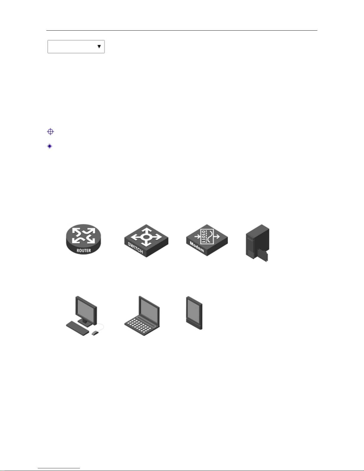
Router Switch Modem Server
Wired client Wireless client PDA
Page 8

UTT Technologies About this Manual
http://www.uttglobal.com Page 3
0.4 Default Factory Settings
The factory default settings of interfaces are shown in the following table.
Parameter Default Value Description
User Name admin
Both the User Name and
Password are case sensitive.
Password admin
LAN IP Address www.uttlogin.com
You can use this IP address to
access the Device through a Web
browser.
Table 0-1 Factory Default Settings of Interface
0.5 Contact us
If you have any question about the installation or using the Device, please contact us as the
following ways:
Phone: +86 21-67766519, 67766527
Global Sales Office Number: +1(626)722-5032
Email:
Page 9
UTT Technologies Hardware Installation
http://www.uttglobal.com Page 4
Chapter 1. Hardware Installation
This chapter describes the physical characteristics of the Device, and explains how to install them.
1.1 Panel Descripti on
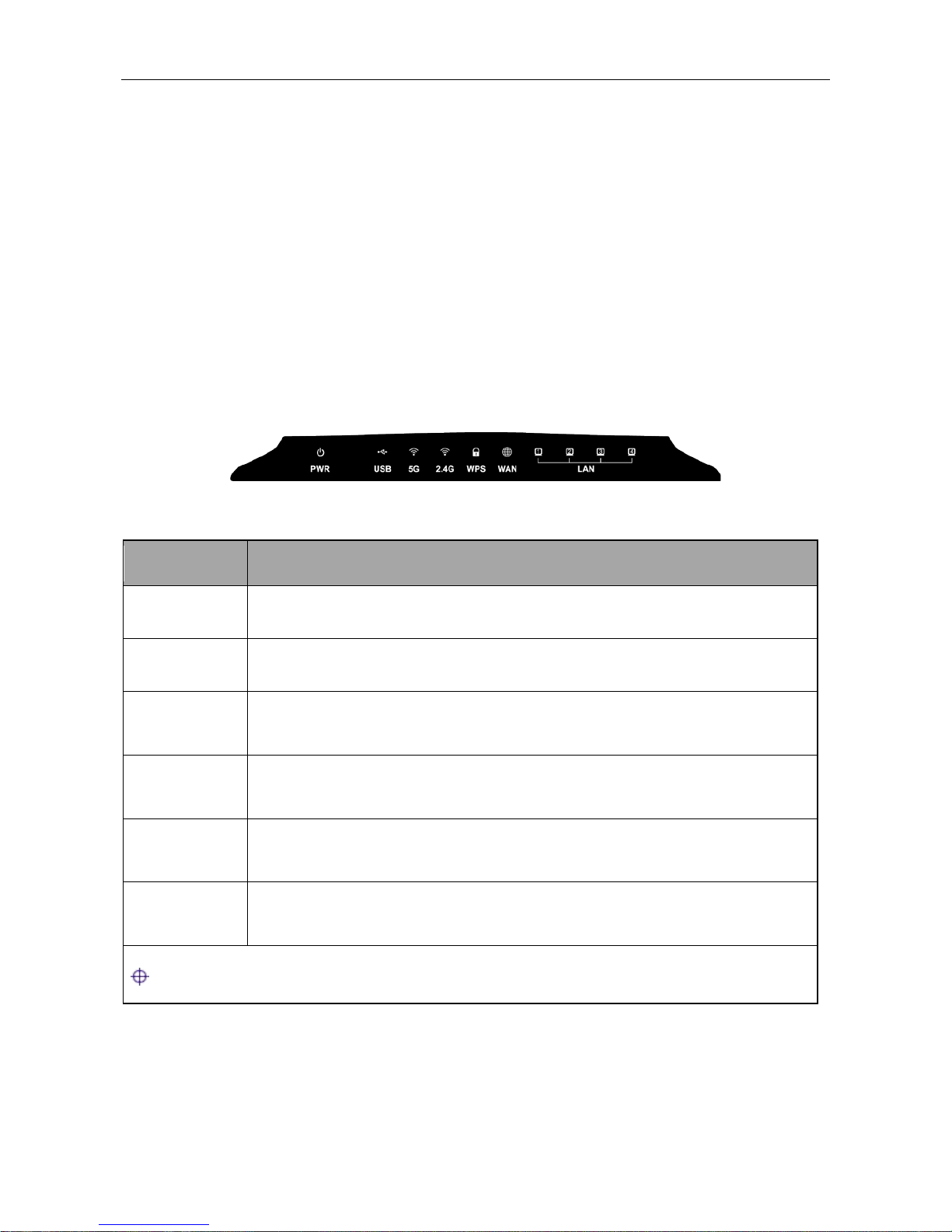
1) Front Panel
The LEDs are located on the front panel of the Device. Here we use UTT AC650W as an example
(see Figure 2-1). As for other models, please see the product.
Figure 1-1 Front Panel-UTT AC650W
LED
Description
PWR The Power LED indicator is on when the Device is powered on.
USB The LED indicator is on when the USB interface is connected properly.
5G
The 5G LED indicator is on when 5GHZ Wireless is enabled, and it blinks
when transmitting/receiving 5G wireless data.
2.4G
The 2.4G LED indicator is on when 2.4GHZ Wireless is enabled, and it blinks
when transmitting/receiving 5G wireless data.
WAN
The WAN LED indicator is on when Ethernet cable connection is normal, and
it blinks when the WAN port is sending or receiving data.
1,2,3,4
The LAN LED indicator is on when Ethernet cable connection is normal, and it
blinks when the LAN port is sending or receiving data.
Note: The number of port status LEDs depends on the Device model.
Table 1-1 LEDs Description
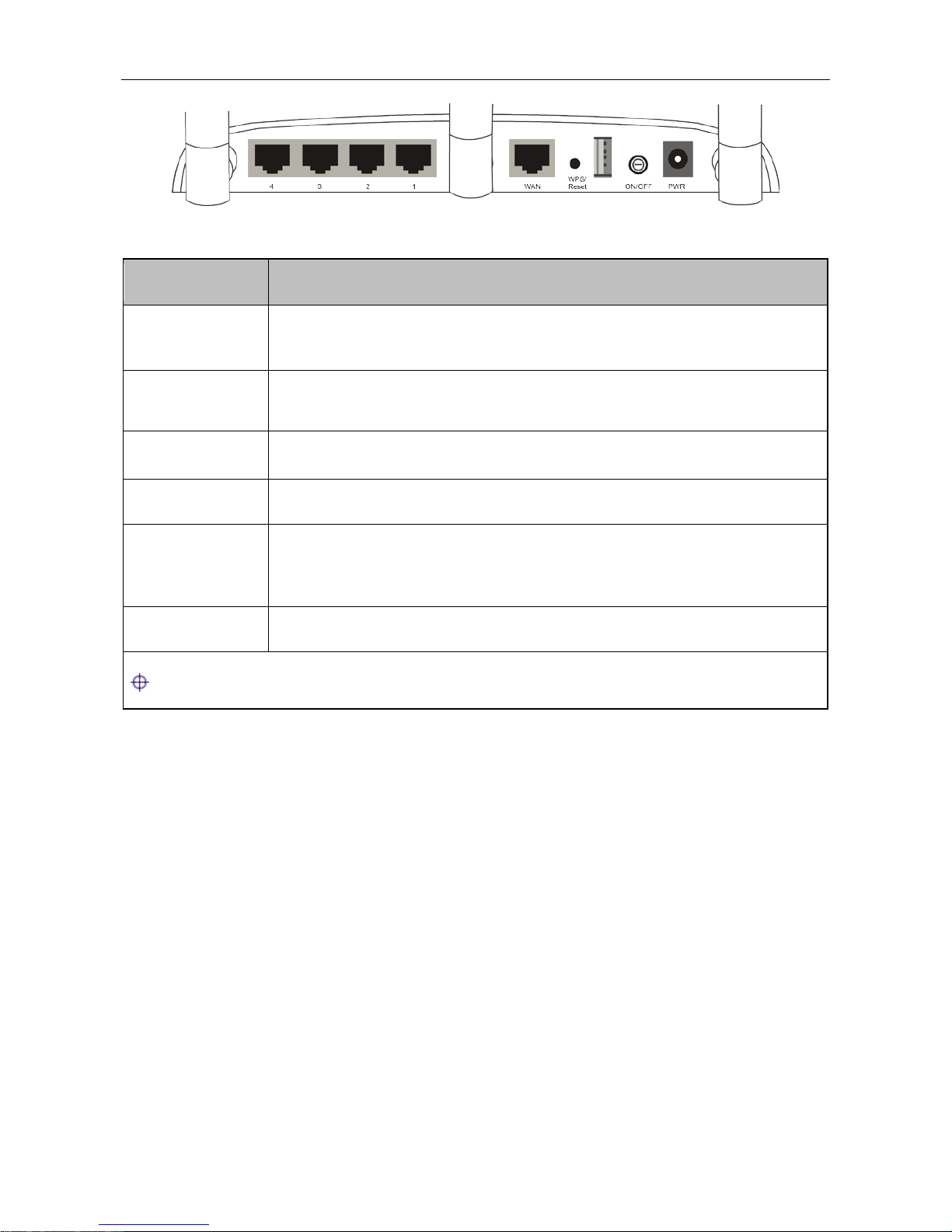
2) Back Panel
The interface and the button are located on the back panel of the Device, here we use UTT
AC650W as an example (see Figure 2-2). As for other models, please see the product.
Page 10
UTT Technologies Hardware Installation
http://www.uttglobal.com Page 5
Figure 1-2 Back Panel-UTT AC 650W
Interface/Button Description
LAN
These interfaces provide a LAN connection to network devices, such as PCs
or switches.
WAN
The WAN interface is connected to your Internet device, such as a cable or
modem.
USB Plug-in a USB storage f or data s haring.
PWR The PWR interface is where you connect the provided power adapter.
Reset
Reset current setti ngs to the factory default settings. When the Device is
powered on, use a pin or paperclip to press and hold the Reset button for
more than 5 seconds, and then release the button. After that, the Device will
restart with the factory default settings.
On/Off Press this button to turn the Device on/off.
Note: The reset operation will clear all the settings that you have configured.
Table 1-2 Interfaces and Buttons Description
1.2 Installation Guideline
When determining where to place the Device, please observe these guidelines:
Make sure that your workbench or standard rack is level and stable.
Do not place heavy objects on the Device!
Make sure that there is proper heat dissipation and adequate ventilation around the Device.
Position the Device out of direct sunlight and away from sources of heat and ignition.
Please install the Device in a place far away from the High Power Radio or Radar Station.
Keep the Device far away from water!
Please use the supplied power cord.
Page 11

UTT Technologies Hardware Installation
http://www.uttglobal.com Page 6
1.3 Installation Req uirements
The following items are required for installation:
1) Broadband Internet connection
2) Tools and equipment
(1) Broadband modem (optional)
(2) PC with an Ethernet card and TCP/IP installed
(3) Network devices like hub, switch, wireless access point
(4) Network cables
(5) Screwdriver
(6) Power outlet
1.4 Installation Procedure
Follow these steps to install the Device on a flat surface such as a bench:
1) Make sure the Device is powered off.
2) Place the Device upside down on a sturdy, flat bench with a power outlet nearby. Verify that the
bench is well grounded.
3) Remove the adhesive backing from the supplied rubber feet. Attach the four rubber feet to the
round recessed areas on the bottom of the Device.
4) Turn the Device over to make it right side up on the bench.
1.5 Connecting the Device
Before you install the Device, please make sure your PC can connect to the Internet through your
broadband service successfully. If there is any problem, please contact with your ISP for help.
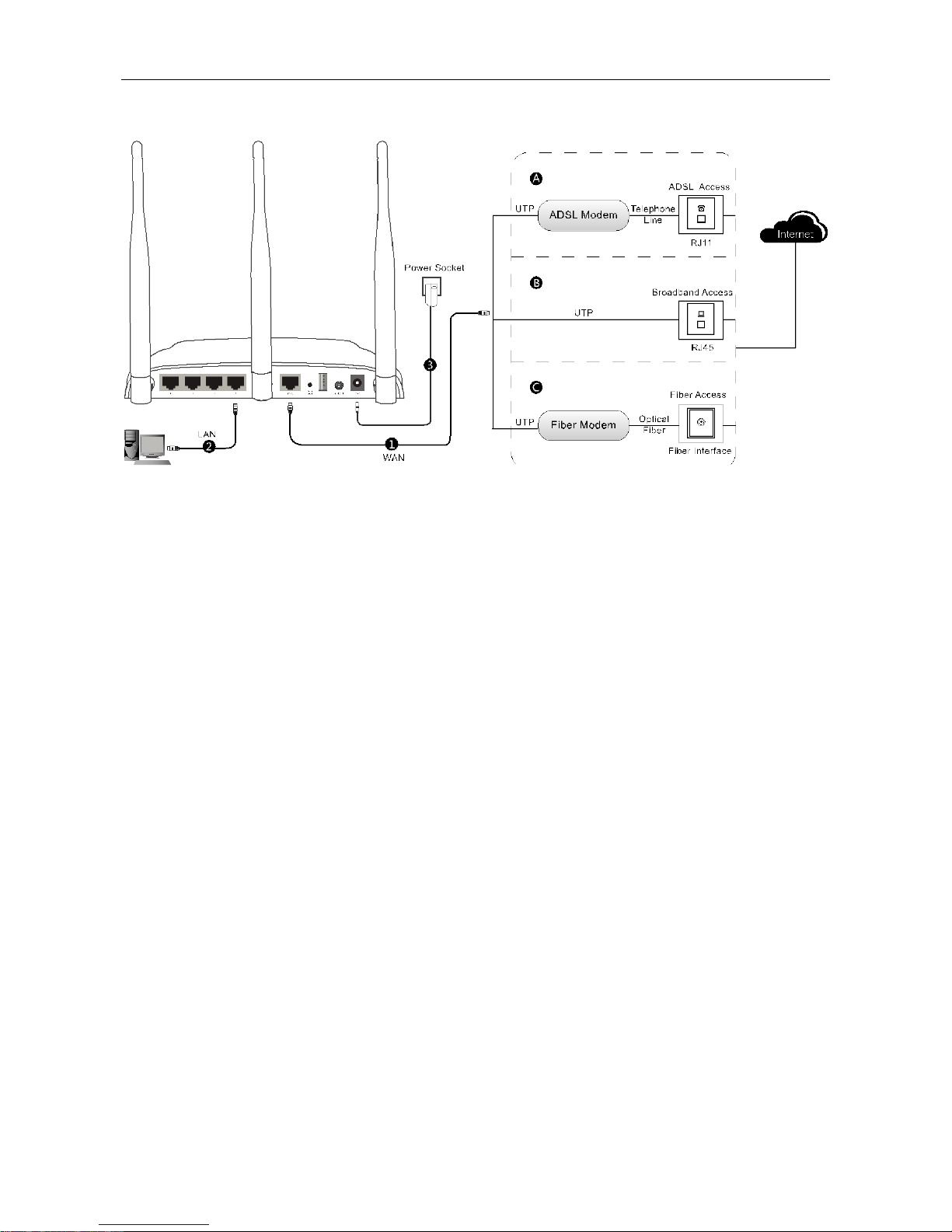
After that, please install the Device according to the following steps. Don’t forget to pull out the
power plug and keep your hands dry.
1) Power off your PC(s), Cable/DSL modem, and the Device.
2) Connect the Cable/DSL modem to the Device’s WAN port.
3) Connect one end of an Ethernet cable to one of the LAN ports on the Dev i ce, and the other end
to a network port on a PC, hub, switch or wireless access point. Repeat this step to connect
more PCs or other network devices to the Device.
4) Connect the power cord to the power port of th e Device. Then plug the other end of the power
cord to a grounded AC power outlet.
Page 12
UTT Technologies Hardware Installation
http://www.uttglobal.com Page 7
5) Power on your network devices, PCs, Switches, Hubs, and so on.
Figure 1-3 Connecting the Device
Page 13

UTT Technologies Logging to the Device
http://www.uttglobal.com Page 8
Chapter 2. Logging to the Device
This chapter describes how to configure TCP/IP settings on your computer, and how to login to the
Device. In addition, it briefly describes the layout of the Device’s Web interface.
2.1 Configuring your computer
To configure the Device via Web UI, you need to properly configure TCP/IP settings on the
computer that you use to manage the Device. To achieve this, follow these steps:
Step 1 Connect the computer to a LAN port of the Device, or connect the computer to the Device
through wireless.
Step 2 Install TCP/IP protocol on your computer. If it is already installed, please skip this step.
Step 3 Configure TCP/IP settings as Obtain an IP address automatically and Obtain DNS
server address automatically. More information about how to configure TCP/IP, please
refer to the chapter:
Appendix A FAQ.
Step 4 Use the Ping command to verify network connectivity between the computer and the
Device. Open the command prompt on the computer, type ping www.uttlogin.com, and
then press Enter.
A successful ping will look like this:
An unsuccessful ping will look like this:
Pinging www.uttlogin.com [192.168.1.1] with 32 bytes of data:
Reply from 192.168.1.1: bytes=32 time<1ms TTL=255
Reply from 192.168.1.1: bytes=32 time<1ms TTL=255
Reply from 192.168.1.1: bytes=32 time<1ms TTL=255
Reply from 192.168.1.1: bytes=32 time<1ms TTL=255
Ping statistics for 192.168.1.1:
Packets: Sent = 4, Received = 4, Lost = 0 (0% loss),
Approximate round trip times in milli-seconds:
Minimum = 0ms, Maximum = 0ms, Average = 0ms
Page 14
UTT Technologies Logging to the Device
http://www.uttglobal.com Page 9
If the Ping command is successful, the connection betw een the compu ter and the Device is working
properly. If the Ping command fails, please do the following:
1) Check physical connection: Verify that the LAN LED on the Device and the LED on your
computer’s network card are lit.
2) Check TCP/IP settings: Verify that your computer is on the same subnet as the Device’s LAN
interface. E.g., if the Device’s LAN IP address is 192.168.1.1, the computer’s IP address must
be an unused IP address in the 192.168.1.0/24 subnet.
2.2 Logging to the Device
No matter what operating system is installed on your computer, such as, MS Windows, Macintosh,
UNIX, or Linux, and so on, you can configure the Device through the Web browser (e.g., Internet
Explorer, Firefox).
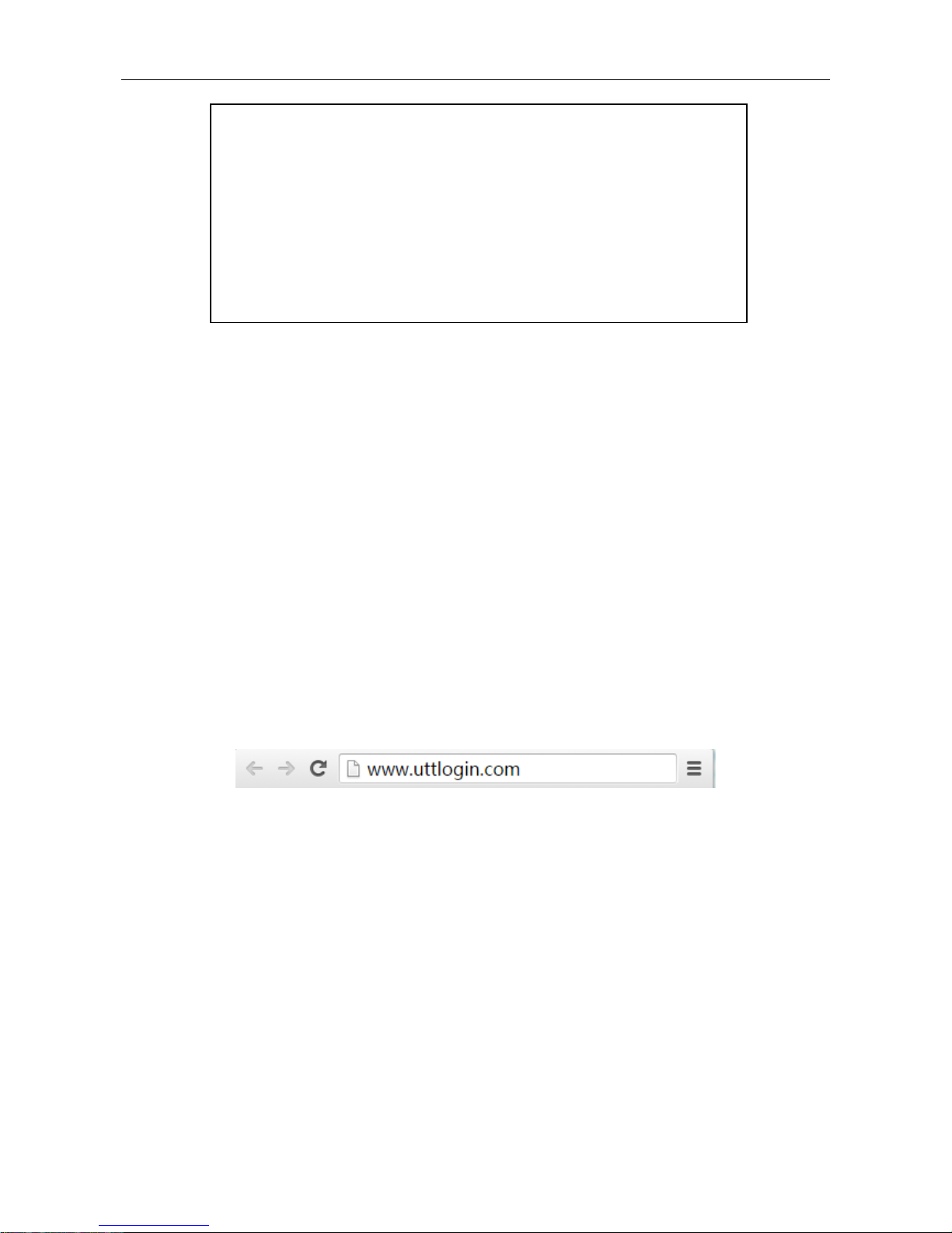
Step 1: For local access of the Device’s web-based utility, launch your web browser, and enter the
Device’s default IP address www.uttlogin.com in the URL filed. Then press the Enter key.
Figure 2-1 Address Bar
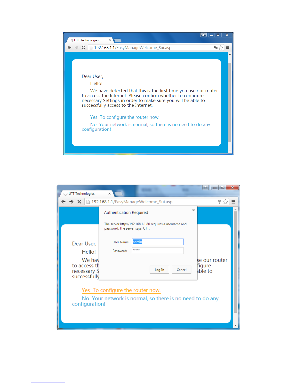
Step 2: The first time you log in the Device, th e system will ask whether you want to configure the
Device right away or later on. We suggest you select YES, To configure the router now. If it’s not
your first time to logging to the Device, please skip this step.
Pinging www.uttlogin.com [192.168.1.1] with 32 bytes of data:
Request timed out.
Request timed out.
Request timed out.
Request timed out.
Ping statistics for 192.168.1.1:
Packets: Sent = 4, Received = 0, Lost = 4 (100% loss)
Page 15
UTT Technologies Logging to the Device
http://www.uttglobal.com Page 10
Figure 2-2 Start Configure Router Screen
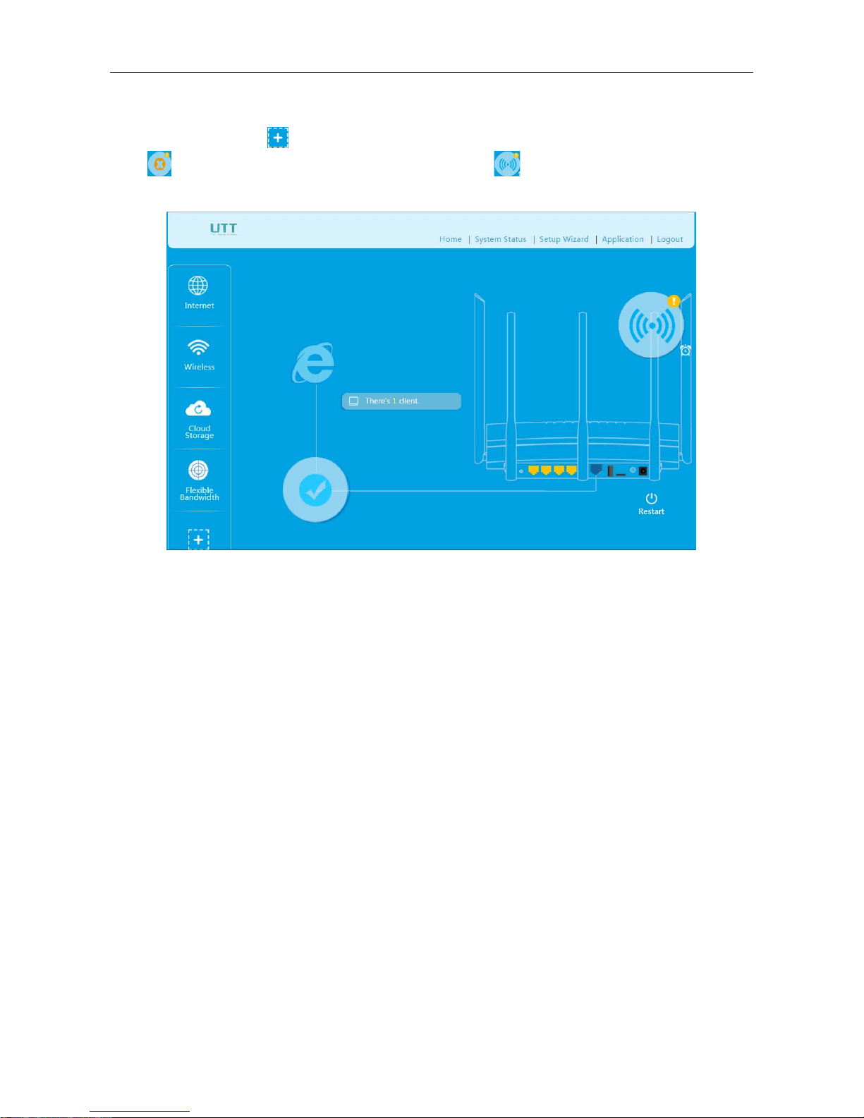
Step 3: A login screen prompts you for User name and Password. Enter admin (case sensitive) in
the User name field, and enter admin in the Password field. Then click Log In.
Figure 2-3 Login Screen
Page 16
UTT Technologies Logging to the Device
http://www.uttglobal.com Page 11
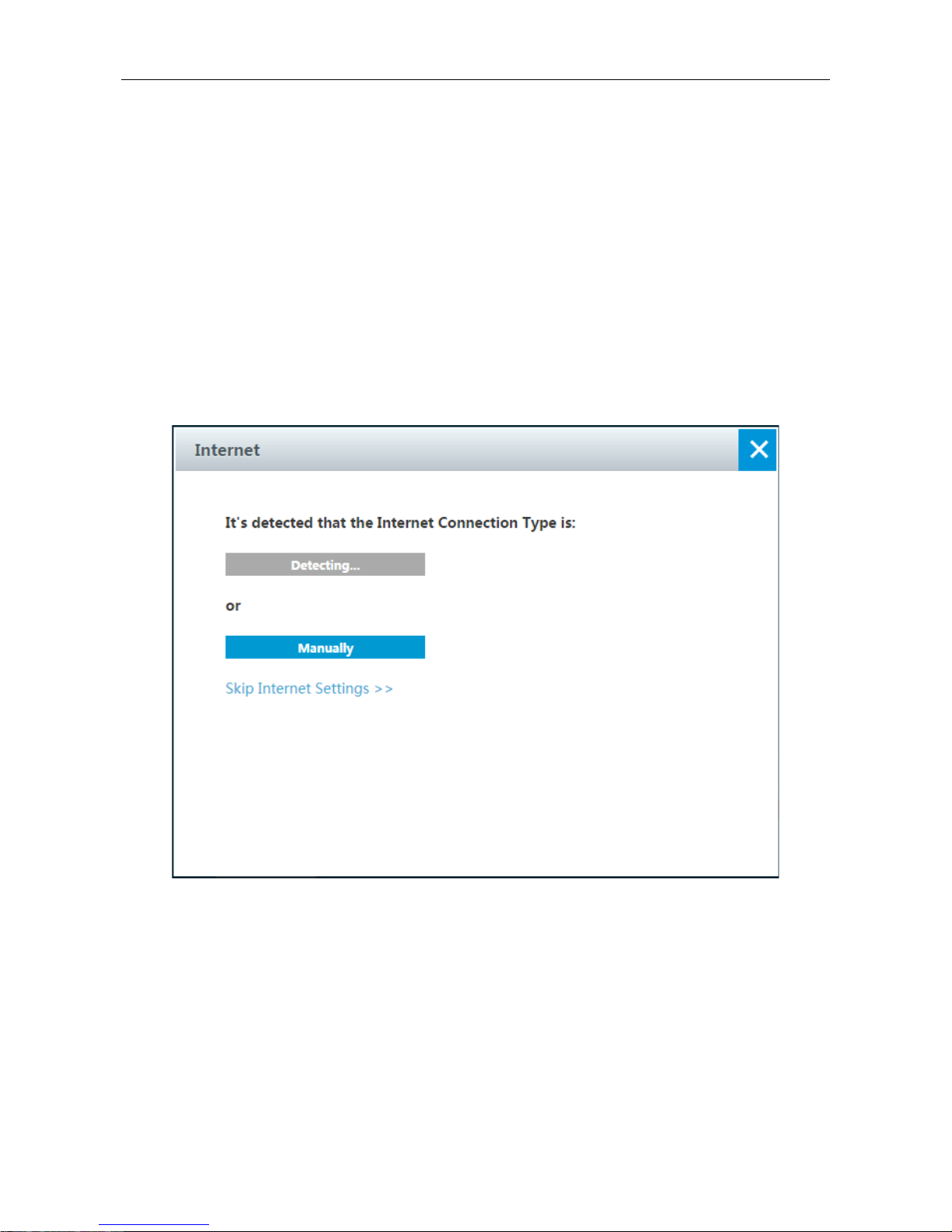
Step 4: Once logged in the Device, the first screen is the homepage, as shown below. On top right
corner there is main menu. On left side there’re frequently-used applications. You can add
applications by clicking
. On the central page there is a network connection diagram. You can
click
to configure how to connect to Internet and click to configure the name/password of
wireless network. You can restart the system by clicking the Restart button.
Figure 2-4 Homepage
Page 17
UTT Technologies Setup Wizard
http://www.uttglobal.com Page 12
Chapter 3. Setup Wizard
This chapter describes how to quickly configure IP address and wireless parameters. After finished
all steps mentioned in this chapter, you shall be able to access Internet.
3.1 Running the Setup Wizard
Clicking the Setup Wizard tab on Homepage, a dialogue w indow s pops up showing that the Device
is detecting the Internet connection type. It will choose a suitable connection type according to the
network. If you want to decide the Internet connection type by yourself, please click the Manually
button on the following figure.
Figure 3-1 Running the Setup Wizard
3.2 Internet
After detecting the Internet connection type, you need to set the parameters to finalize the
configuration. There are three connection types: PPPoE, Dynamic IP and Static IP.
Page 18
UTT Technologies Setup Wizard
http://www.uttglobal.com Page 13
3.2.1 PPPoE
Most DSL-based Internet Service Providers (ISPs) use PPPoE (Point-to-Point Protocol over
Ethernet) to establish Internet connections for end-users. If you use a DSL line, check with your ISP
to see if they use PPPoE, and then select PPPoE.
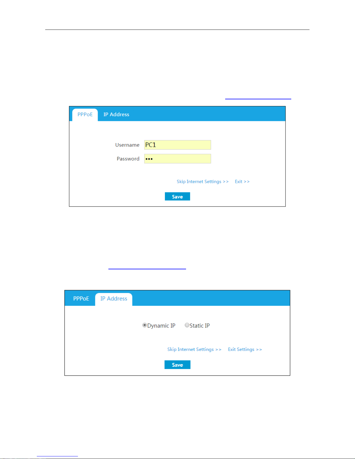
Enter the username and the password provided by ISP in the following dialogue, then click the Save
button. For More inform ation about PPPoE, please refer to section: 4.5.1 PPPoE Connection.
Figure 3-2 PPPoE
3.2.2 Dynamic IP
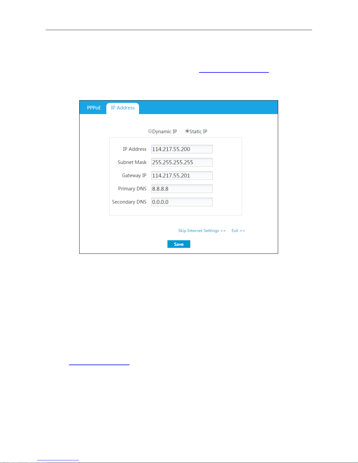
If your ISP assigns an IP address automatically, please select Dynamic IP as connection type.
Most cable modem subscribers use this connection type. More information about Dynamic IP,
please refer to section: 4.5.2 Dynamic IP Connection.
Select Dynamic IP in the following dialogue window, then click the Save button.
Figure 3-3 Dynamic IP
Page 19
UTT Technologies Setup Wizard
http://www.uttglobal.com Page 14
3.2.3 Static IP
If you are required to use a permanent IP address, please select Static IP to access Internet. For
more information about Static IP, please refer to section: 4.5.3 Static IP Connection.
Enter the information provided from ISP into the following dialogue window, and click the Save
button.
Figure 3-4 Static IP
3.3 Wireless
This section describes how to quickly configure the wireless network. There are two wireless
connections bands: 2.4GHz and 5GHz (Only dual-band wireless router support 5GHz).
3.3.1 2.4GHz Wireless
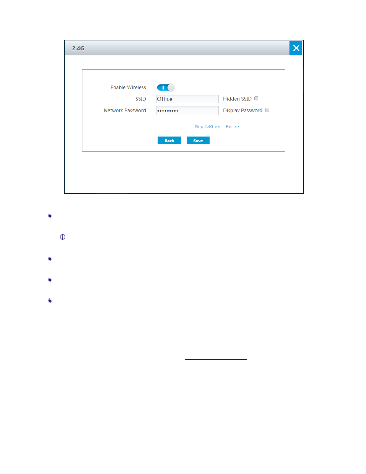
In the following dialogue window, you can enable 2.4GHz band of wireless, and configure the name
and password of the wireless network. For more information about 2.4GHz wireless, please refer to
section:
4.6.1 2.4GHz Wireless.
Page 20
UTT Technologies Setup Wizard
http://www.uttglobal.com Page 15
Figure 3-5 Setup Wizard_2.4G Wireless Settings
SSID: The SSID (Service Set Identification) is also known as the wireless network name, which
is used to uniquely identify a wireless network.
Notes: The Device supports double SSID On 2.4GHz wireless mode. This is th e default
SSID.
Hidden SSID: If selected, the SSID will be hidden. In th i s cas e, if users want to access this
wireless network, they need to set SSID manually on their end devices.
Network Password: Specify the password for the wireless network. That is displayed in a
cipher text form.
Display Password: If selected, the password will be displayed in a plain text form.
3.3.2 5GHz Wireless
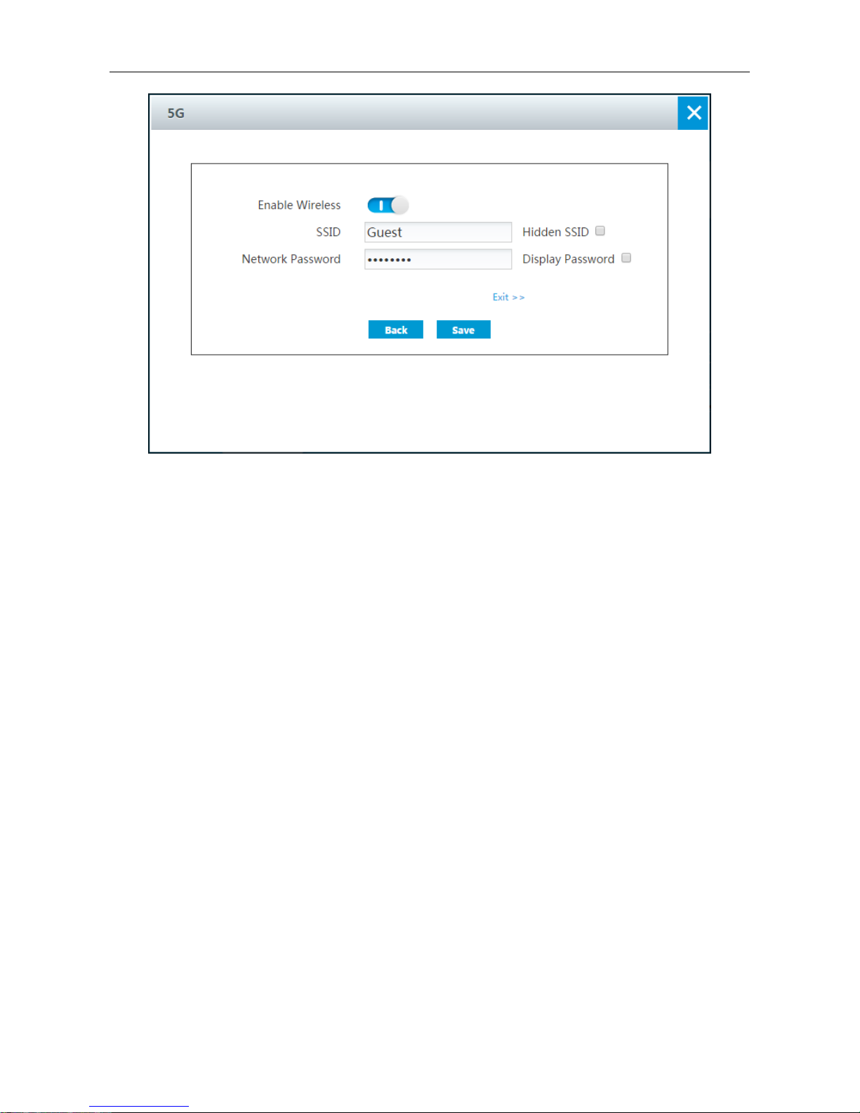
In the following dialogue window, you can enable 5GHz band of wireless, and configure the name
and the password of the wireless network. The settings of parameters for 5GHz wireless are the
same as 2.4GHz wireless, please refer to section:
3.3.1 2.4GHz Wireless. For more information
about 5GHz wireless, please refer to section:
4.6.2 5GHz wireless.
Page 21
UTT Technologies Setup Wizard
http://www.uttglobal.com Page 16
Figure 4- 1 Setup Wizard_5G Wireless Settings
Once completed the above steps, you shall be able to access Internet successfully.
Page 22
UTT Technologies Application
http://www.uttglobal.com Page 17
Chapter 4. Application
The Device supports lots of functions, such as: DHCP, DDNS, MAC Filter, Bandwidth Control,
Virtual Server, Remote management, Cloud storage and so on. We will introduce them in detail in
this chapter.
4.1 DHCP server
The Dynamic Host Configuration Protocol (DHCP) provides a framework for passing configuration
information to hosts on a TCP/IP network. DHCP allows a host to be configured automatically,
eliminating the need for intervention by a network administrator. The Device can act as a DHCP
server to assign network addresses and deliver other TCP/IP configuration parameters (such as
gateway IP address, DNS server IP address, etc.) to the LAN hosts.
A DHCP address pools contains specific IP configuration details that the DHCP server can assign
to clients. The Device provides a default DHCP address pool with a name o f DHCP Pool. By default,
the Device assigns IP addresses from the default address pool. You can add one or more custom
address pools for different wireless subnets. Note that wireless address pools will only serve
wireless clients but not wired clients.
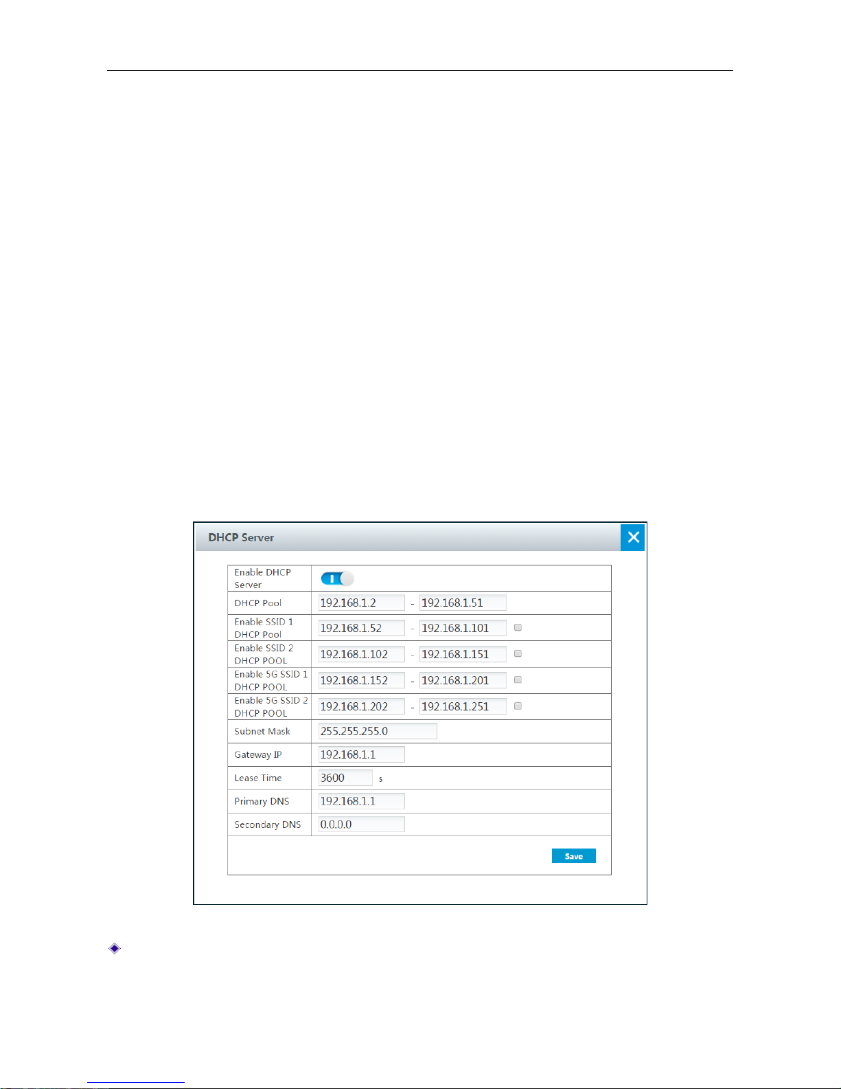
Figure 4-1 DHCP Server
Enable DHCP Server: Click to enable the DHCP server.
Page 23

UTT Technologies Application
http://www.uttglobal.com Page 18
DHCP Pool: Specify the range of IP addresses assigned to DHCP clients. The range of IP
addresses must be on the same subnet as the LAN interface of the Device, and cannot include
the IP address of the LAN interface.
Enable SSID1 DHCP Pool or Enable SSID2 DHCP Pool: Specify the range of IP addresses
assigned to DHCP clients for 2.4GHz. The range of IP addresses must be on the same subnet
as the LAN interface of the Device, and cannot include the IP address of the LAN interface.
Enable 5G SSID1 DHCP Pool or Enable 5G SSID2 DHCP Po ol: Specify the ra nge of IP
addresses assigned to DHCP clients for 5GHz. The range of IP addresses must be on the
same subnet as the LAN interface of the Device, and cannot include the IP address of the LAN
interface.
Subnet Mask: The subnet mask address assigned by the DHCP server to the intranet
computers, mobile phones and other clients automatically. This subnet mask must match the
subnet mask of the LAN interface.
Gateway IP: Specify the gateway IP address assigned by the DHCP server to the intranet
computers, mobile phones and other clients automatically. This gateway IP address must
match the gateway IP address of the LAN interface.
Lease Time: The leasing time for the Intranet clients to obtain the IP address assigned by the
Device (Unit: Seconds).
Primary DNS S erv er: The primary DN S server IP address assigned by the D HCP server to the
Intranet computers, mobile phones and clients automatically.
Secondary DNS Server: The secondary DN S server IP address assigned by the DHCP server
to the Intranet computers, mobile phones and other clients automatically.
Note:
1) If you want a LAN PC to obtain an IP address and other parameters from the Device’s built-in
DHCP server, please configure the PC to obtain an IP address automatically.
2) If you already have a DHCP server on your network, it is recommended that you do not enable
DHCP server on the Device to avoid IP address conflicts.
4.2 DDNS
Dynamic Domain Name Service (DDNS) is a service used to map a domain name which never
changes to a dyna m ic I P address which may frequently change. For example, if you have applied
PPPoE connection with dynamically assigned IP address from the ISP, you can use DDNS to allow
the external computers to access the Device by a static domain name.
In order to use DDNS service, you need to register an account with a DDNS provider. Each DDNS
provider offers its own specific network services. The DDNS service provider reserves the right to
change, suspend or terminate your use of some or all network services at any time for any reason.
The DDNS service providers supported by UTT Technologies currently provide free DDNS services,
but they may charge for the DDNS services in the future. In this case, UTT Technologies will notify
you as soon as possible; if you refuse to pay for the serv ices, you wi ll no lo nger be able to use the m.
During the free phase, UTT Technologies does not guarantee that the DDNS services can meet
your requirements and will be uninterrupted, and UTT does not guarantee the timeliness, security
and accuracy of the services.
Page 24
UTT Technologies Application
http://www.uttglobal.com Page 19
4.2.1 DDNS Service provided by 3322.org
1) Register a Domain Name with 3322.org
Please login to
http://www.3322.org to register a domain name with the suffix of 3322.org.
2) DDNS Settings – 3322.org
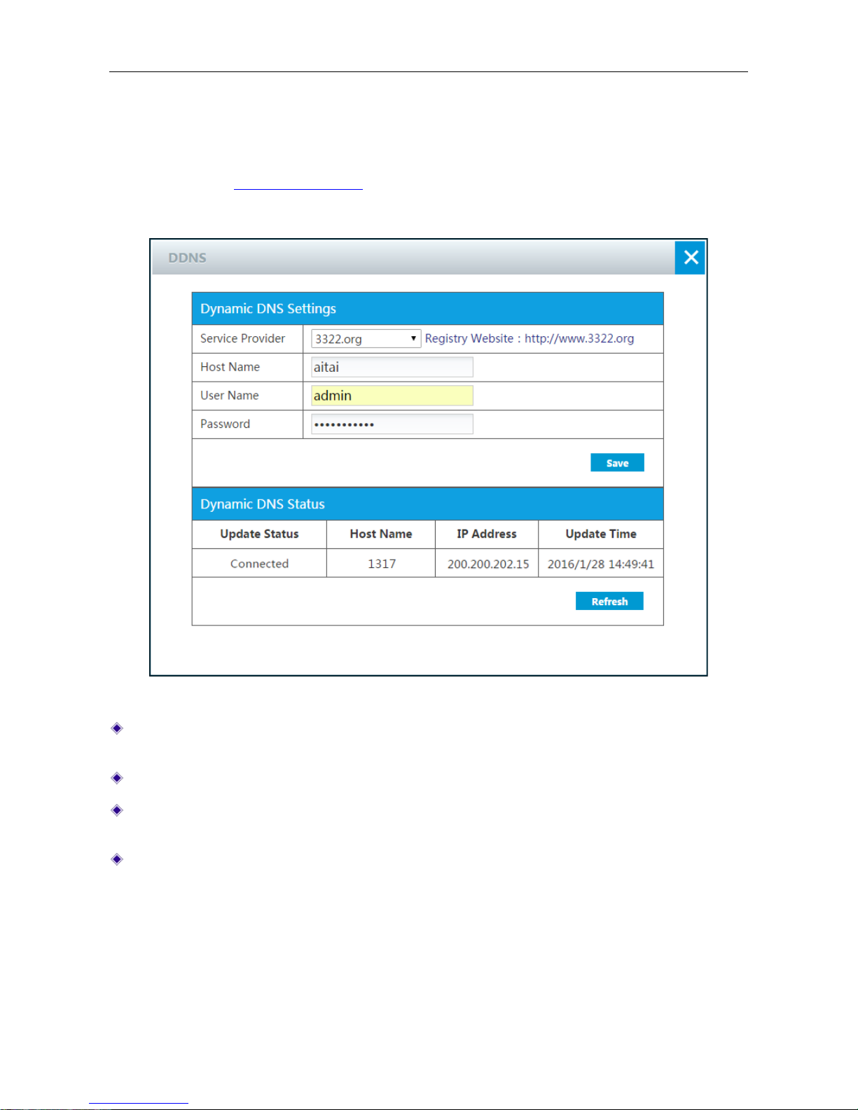
Figure 4-2 DDNS_3322.org
Service Provider: Select the DDNS service provider who offers services to the Device. Here
please select 3322.org.
Host Name: Specify the host name of the Device.
User Name: Enter the user name of the account. I t should be the same wi th the user name that
you entered when registering the DDNS account.
Password: Enter the key that you got when registering the DDNS account.
4.2.2 DDNS Service provided by Peanut shells
To use DDNS offered by peanut shells on the Device, you should have a DDNS account which
includes a fully qualified domain name (FQDN).
Page 25
UTT Technologies Application
http://www.uttglobal.com Page 20
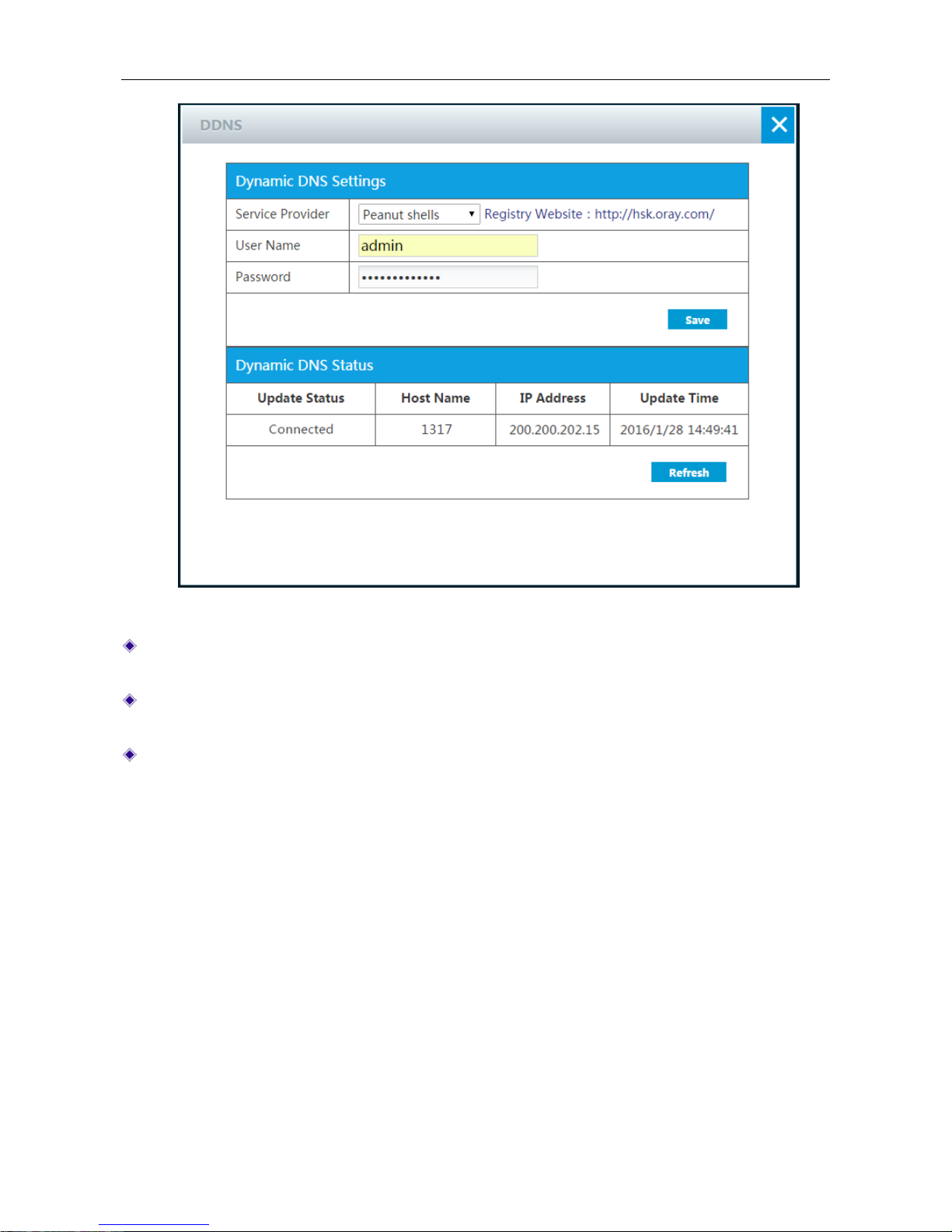
Figure 4-3 DDNS_Peanut shells
Service Provider: Select the DDNS service provider who offers services to the Device. Here
please select Peanut shells.
User Name: Specify the user name of the account. It should be the same with the user name
that you entered when registering the DDNS account.
Password: Enter the key that you got when registering the DDNS account.
4.2.3 DDNS Service provided by uttcare.com
To use DDNS offered by uttcare.com on the Device, you can use the default configuration the
Device provided or you can go to UTT website to apply for a DDNS account which includes a fully
qualified domain name with suffix of uttcare. c om and a key.
Page 26
UTT Technologies Application
http://www.uttglobal.com Page 21
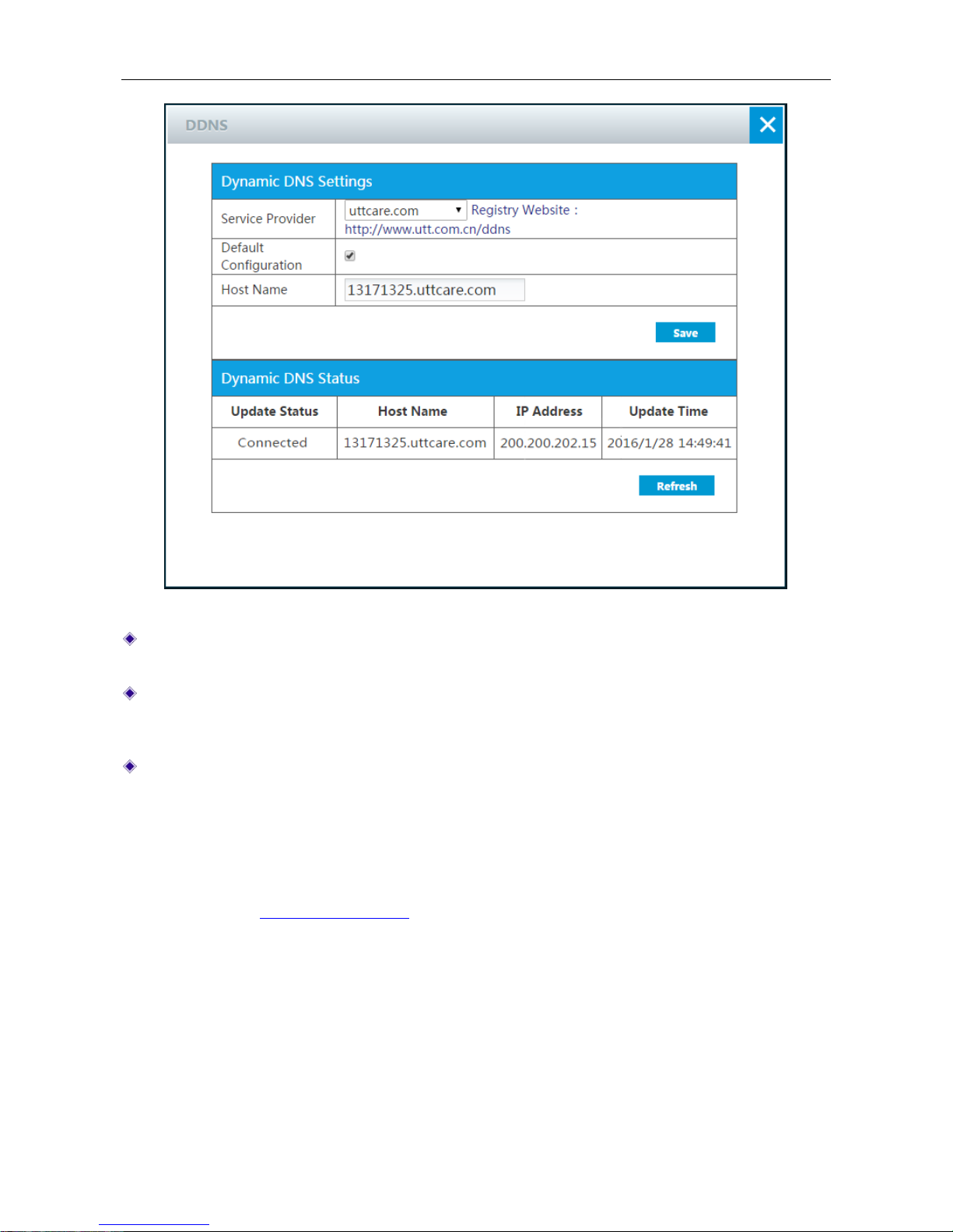
Figure 4-4 DDNS_uttcare.com
Service Provider: Select the DDNS service provider who offers services to the Device. Here
please select uttcare.com.
Default Configuration: If selected, the Device will generate a host name as domain name,
else please enter the host name and password word you got when registering the DDNS
account.
Host Name: The host name of the Device.
4.2.4 DDNS Service provided by no-ip.com
1) Register a Domain Name with no-ip.com
Please login to
http://www.noip.com/ to register a domain name with the suffix of no-ip.com.
2) DDNS Settings – no-ip.com
Page 27
UTT Technologies Application
http://www.uttglobal.com Page 22
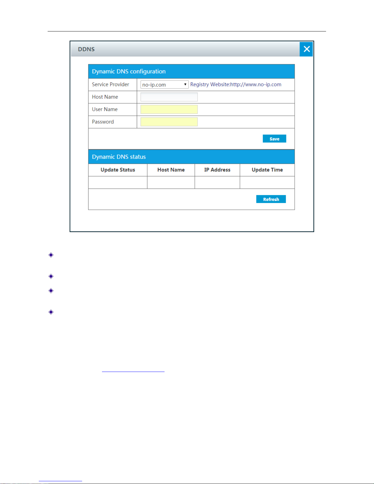
Figure 4-5 DDNS_no-ip.com
Service Provider: Select the DDNS service provider who offers services to the Device. Here
please select no-ip.com.
Host Name: Specify the host name of the Device.
User Name: Enter the user name of the account. It should be the same wi th the user name that
you entered when registering the DDNS account.
Password: Enter the key that you got when registering the DDNS account.
4.2.5 DDNS Service provided by dyndns.org
1) Register a Domain Name with dyndns.org
Please login to
http://www.dyndns.org to register a domain name with the suffix of dyndns.org.
2) DDNS Settings –dyndns.org
Page 28
UTT Technologies Application
http://www.uttglobal.com Page 23
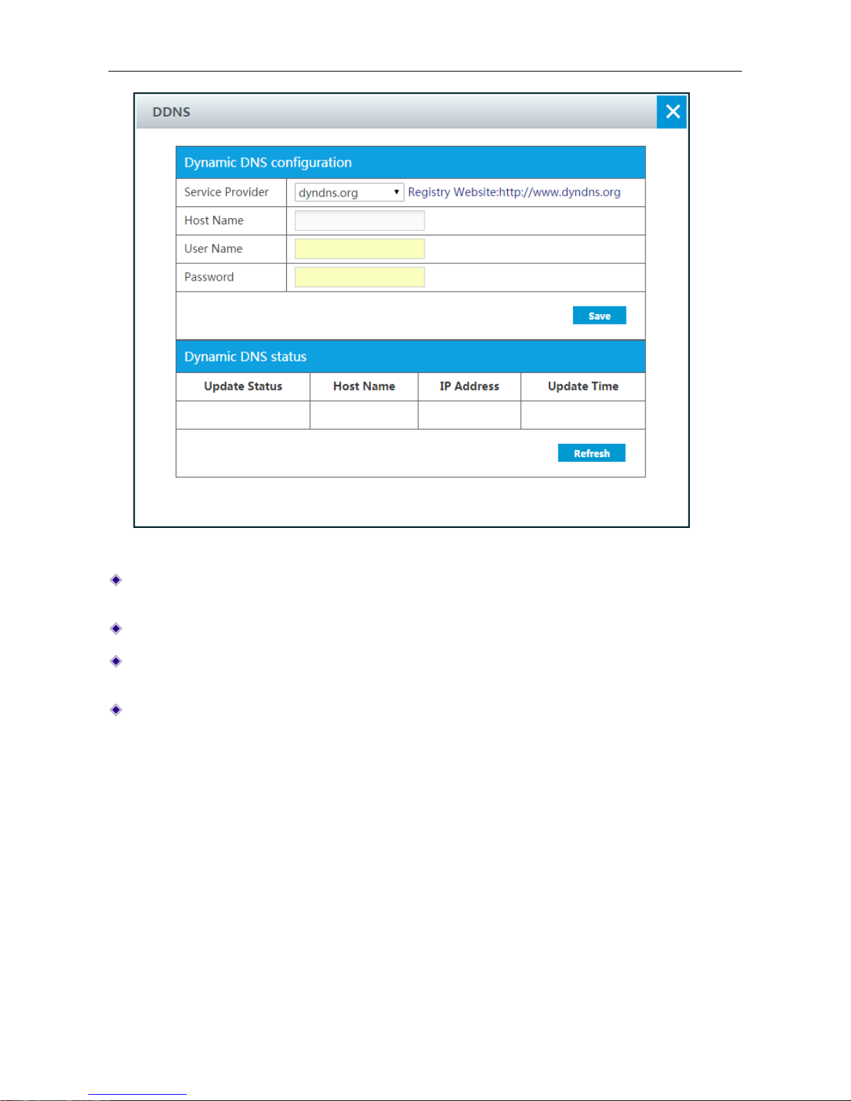
Figure 4-6 DDNS_dyndns.org
Service Provider: Select the DDNS service provider who offers services to the Device. Here
please select dyndns.org.
Host Name: Specify the host name of the Device.
User Name: Enter the user name of the account. It should be the same wi th the user name that
you entered when registering the DDNS account.
Password: Enter the key that you got when registering the DDNS account.
4.2.6 DDNS Verification
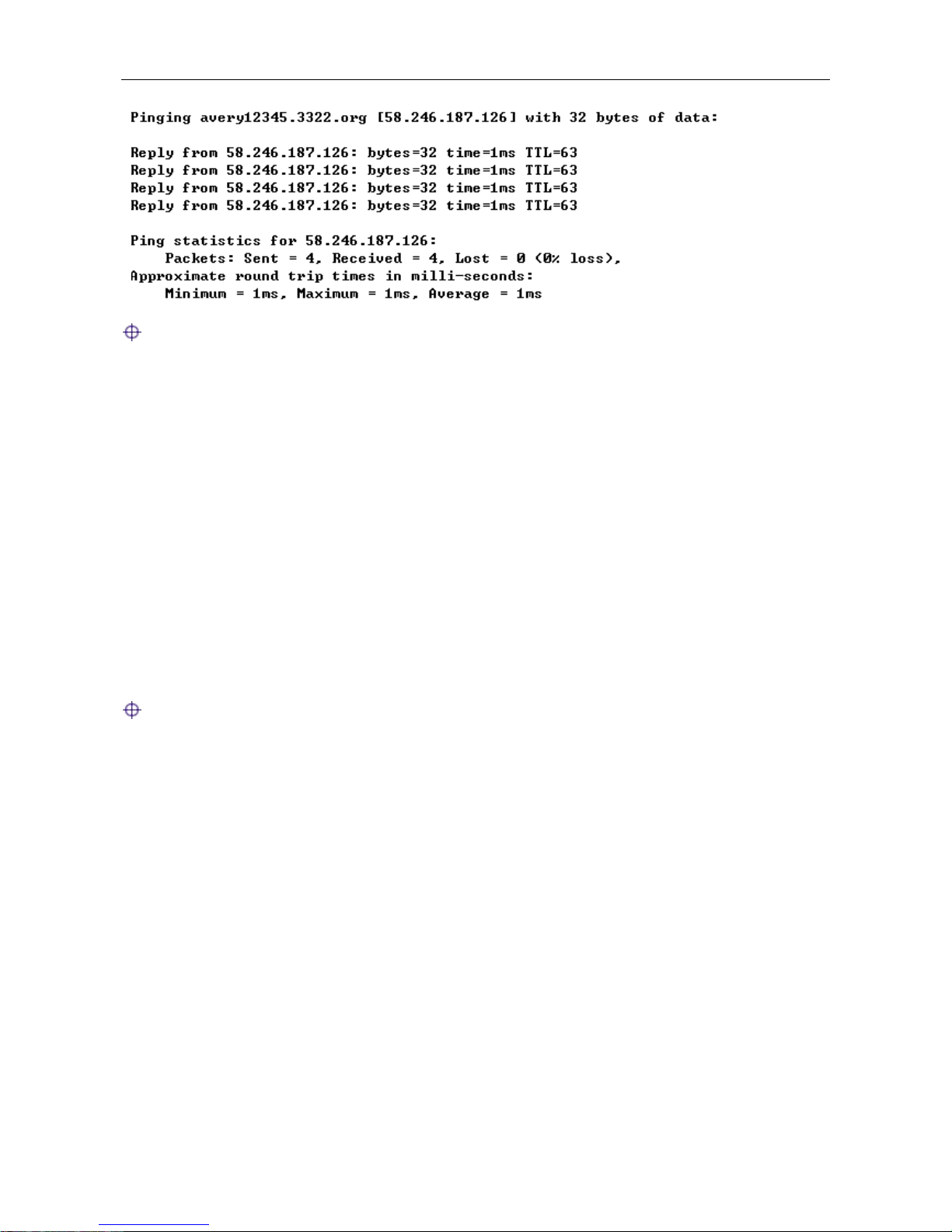
To verify whether DDNS is updated successfully, you can use the ping command at the command
prompt on the PC (for example: ping avery12345.3322.org).
If the displayed page is similar to the screenshot below, the domain name is resolved to an IP
address successfully (58.246.187.126 in this example), that is, DDNS is updated successfully.
Page 29
UTT Technologies Application
http://www.uttglobal.com Page 24
Note:
1) If your ISP assigns a private IP address (192.168.x.x, 10.x.x.x, or 172 .16.x.x) instead o f a publ ic
IP address to the Device, DDNS will not work.
2) DDNS feature can help you implement VPN tunnels using dynamic IP addresses on the
Device.
4.3 Traffic
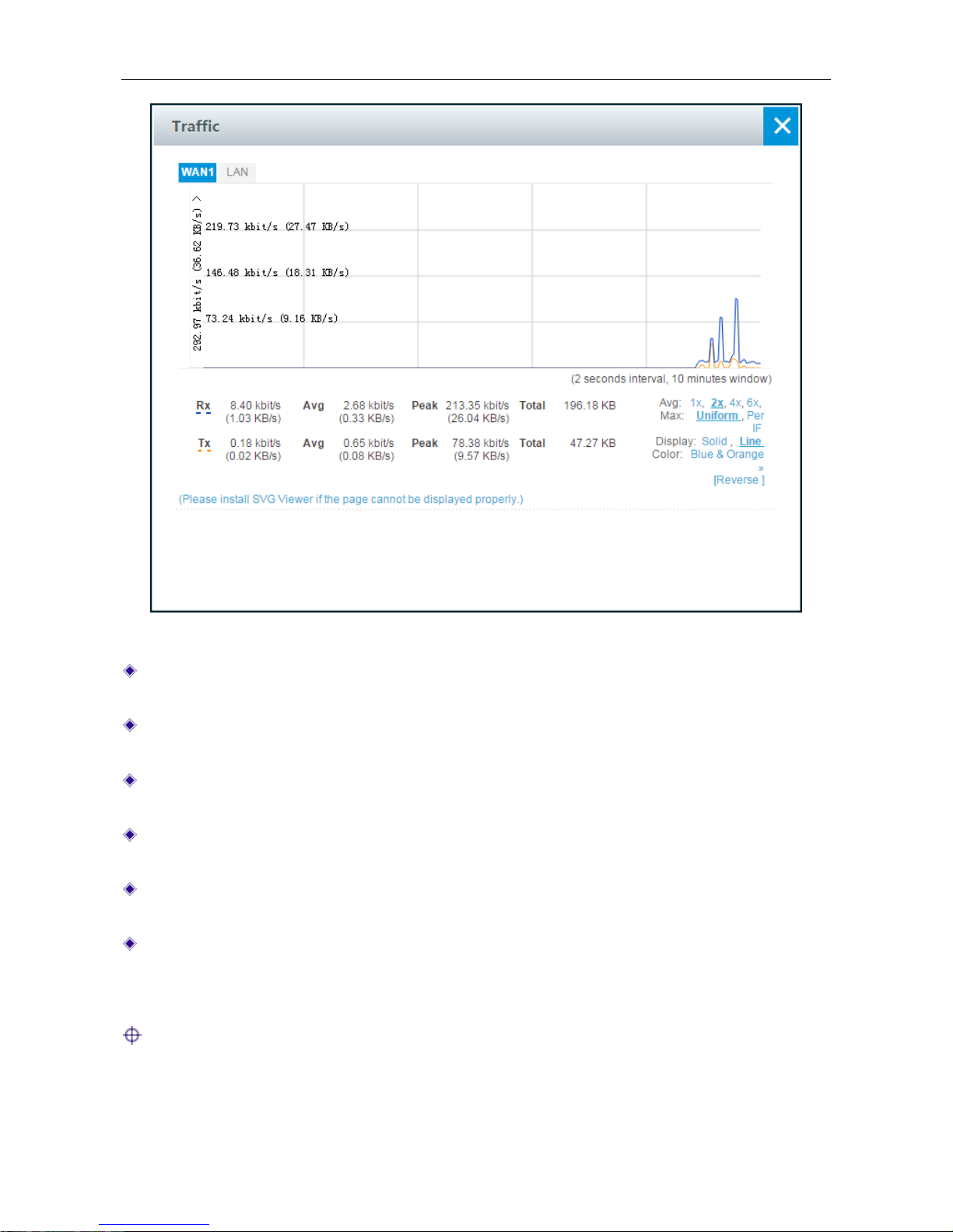
The Traffic rate chart dynamically displays the real-time RX/TX rate, av erage RX/TX rate, max i mu m
RX/TX rate and total RX/TX traffic of each physical interface. If you want to v i ew the rate chart o f a n
interface, click the corresponding interface name hyperlink.
In the interface rate chart, the abscissa (x-axis) shows the time axis, and the ordinate (y-axis) shows
the real-time RX/TX rate axis. Furthermore, you can adjust some parameters of the chart if needed,
such as the time interval during which the real-time rates are calculated and displayed, and the
displayed colors.
Note: The rate chart can only show the rate and traffic information in the la st ten minutes. Each
time you launch this page, the rate chart refreshes.
Page 30
UTT Technologies Application
http://www.uttglobal.com Page 25
Figure 4-7 Traffic
RX: Displays the real-time RX rate o f the physical interface, which refreshes every two seconds.
For the LAN interface, RX means uploading; for the WAN interface, it means downloading.
TX: Displays the real-time TX rate of the physical interface, w hich refreshes every two seconds.
For the LAN interface, TX means downloading; for the WAN interface, it means uploading.
Avg: Displays the average RX or TX rate of the physical interface since last opened the current
page.
Peak: Displays the maximum RX or TX rate of the physical interface since last opened the
curre nt page.
Total: Displays the total RX or TX traffic of the physical interface since last opened the current
page.
LAN/WANx: Click the interface name hyperlink to view the rate chart of the selected interface.
Therein, x (value: 1, 2, 3, 4) indicates the corresponding WAN interface, and the number of
WAN interfaces depends on the specific product model. For example, click the WAN1 hyperlink
to view the rate chart of the WAN1 interface.
Note:
If the SVG Viewer isn’t installed on your PC, the rate chart cannot be displayed properly. To view
the rate chart, click the (Please install SVG Viewer if the page cannot display properly.)
hyperlink to download and install the SVG Viewer.
Page 31
UTT Technologies Application
http://www.uttglobal.com Page 26
4.4 System Info
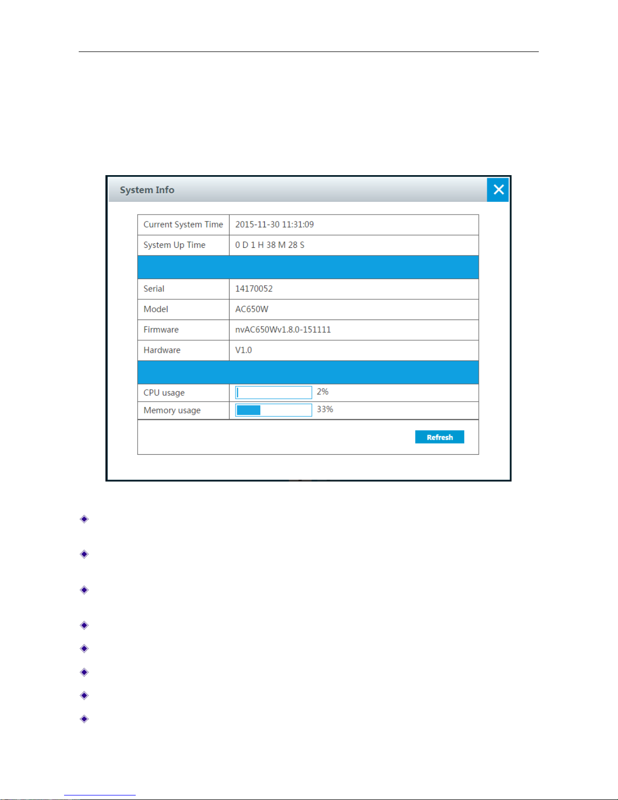
This section describes Application > System Info page, administrators can view system
information, such as current system time, system up time, system resources usage information, SN,
firmware version, etc. Through system information, administrator can identify and diagnose the
source of network problems or potential problems, which helps improve the network performance
and enhance network security.
Figure 4-8 System Info
Current System Time: Displays the current system date (YYYY-MM-DD) and time
(HH:MM:SS) of the Device.
System Up Time: Displays the elapsed time (in days, hours, minutes and seconds) since the
Device was last started.
Serial: Displays the internal serial number of the Device, which may be different from the SN
found on the label at the bottom of the Device.
Model: Displays the model of the Device.
Firmware: Displays the software version number of the Device.
Hardware: Displays the hardware version number of the Device.
Refresh: Click to view the latest system inform ation.
CPU usage: Displays the percentage of the current CPU utilization.
Page 32

UTT Technologies Application
http://www.uttglobal.com Page 27
Memory usage: Displays the percentage of the current memory usage.
Note:
The CPU usage and Memory usage are display ed as a status bar and pe rcentage value. The colo r
of the status bar indicates the usage percentage for each resource.
W hen the percentage is below 1%, the bar is blank.
W hen the percentage is above 1%, the bar is blue.
4.5 Internet
We can access to the Internet application by clicking Application > Internet or clicking at
homepage. There are three connection types: PPPoE, Static I P and Dynamic IP (Obtain an IP
automatically). Depending on which connection type you select, you will see various settings. We
will describe the settings for each connection type respectively.
4.5.1 PPPoE Connection
The Point-to-Point Protocol over Ethernet (PPPoE) is a network protocol for encapsulatin g PP P
frames inside Ethernet frames. Some DSL-based Internet Service Providers (ISPs) use PPP oE
to establish Internet connections for end-users. If you use a DSL line, check with your ISP to
see if they use PPPoE, and then select PPPoE.
Page 33
UTT Technologies Application
http://www.uttglobal.com Page 28
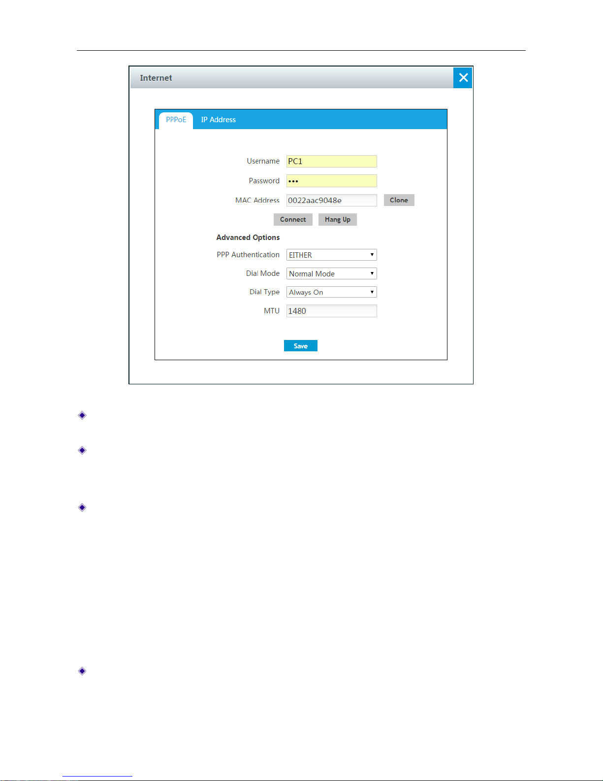
Figure 4-9 PPPoE Connection setting
User Name and Password: Enter the PPPoE login user name and password provided by your
ISP.
MAC Address: Displays the Device’s physical address. We recommend keeping it as default.
Advanced Options: Click to configure advanced parameters. In most case, you don’t need to
configure them.
PPP Authentication: Sp ecify the PPP au thentication mode, av ailabl e options are NONE, PAP,
CHAP and Either.
None: If selected, no protocol will be used.
PAP: If selected, PAP(Password Authentication Protocol) protocol will be used for PPP
authentication.
CHAP: If select e d, CHAP (Challenge Handshake Authentication Protocol) protocol will be
used for PPP authentication.
Either: If selected, the Device will automatically negotiate with the peer device to use PAP
or CHAP protocol.
Dial Mode: If the PPPoE connection isn’t established successfully even using correct user
name and password, you may try other modes.
Page 34

UTT Technologies Application
http://www.uttglobal.com Page 29
Dial Type: Select the type of dial connection, available options are Alw ays On, On Demand
and Manual.
Always On: If selected, the Device will establish a PPPoE session when starting up and
automatically re-establish the PPPoE session once disconnected.
On Demand: If selected, the Device will establish a PPPoE session only when there are
packets requesting to access the Internet (i.e., when a program on your computer attempts
to access the Internet).
Manual: If selected, you can dial or hang up a PPPoE session manually.
MTU: When dialing, the Device will automatically negotiate MTU (maximum transmission unit)
with the peer device. Please leave the default value of 1480 bytes, unless you have a special
application.
4.5.2 Dynamic IP Connection
The Dynamic Host Configuration Protocol (DHCP) is a standardized network protocol used on IP
networks for dynamically distributing network configuration parameters, such as IP addresses for
interfaces and services. With DHCP, computers request IP addresses and networking parameters
automatically from a DHCP server, reducing the need for a network administrator or a user to
configure these settings manually.
If your ISP automatically assigns an IP address, select Dy namic IP. Most cable modem subscribers
use this connection type.
Page 35
UTT Technologies Application
http://www.uttglobal.com Page 30
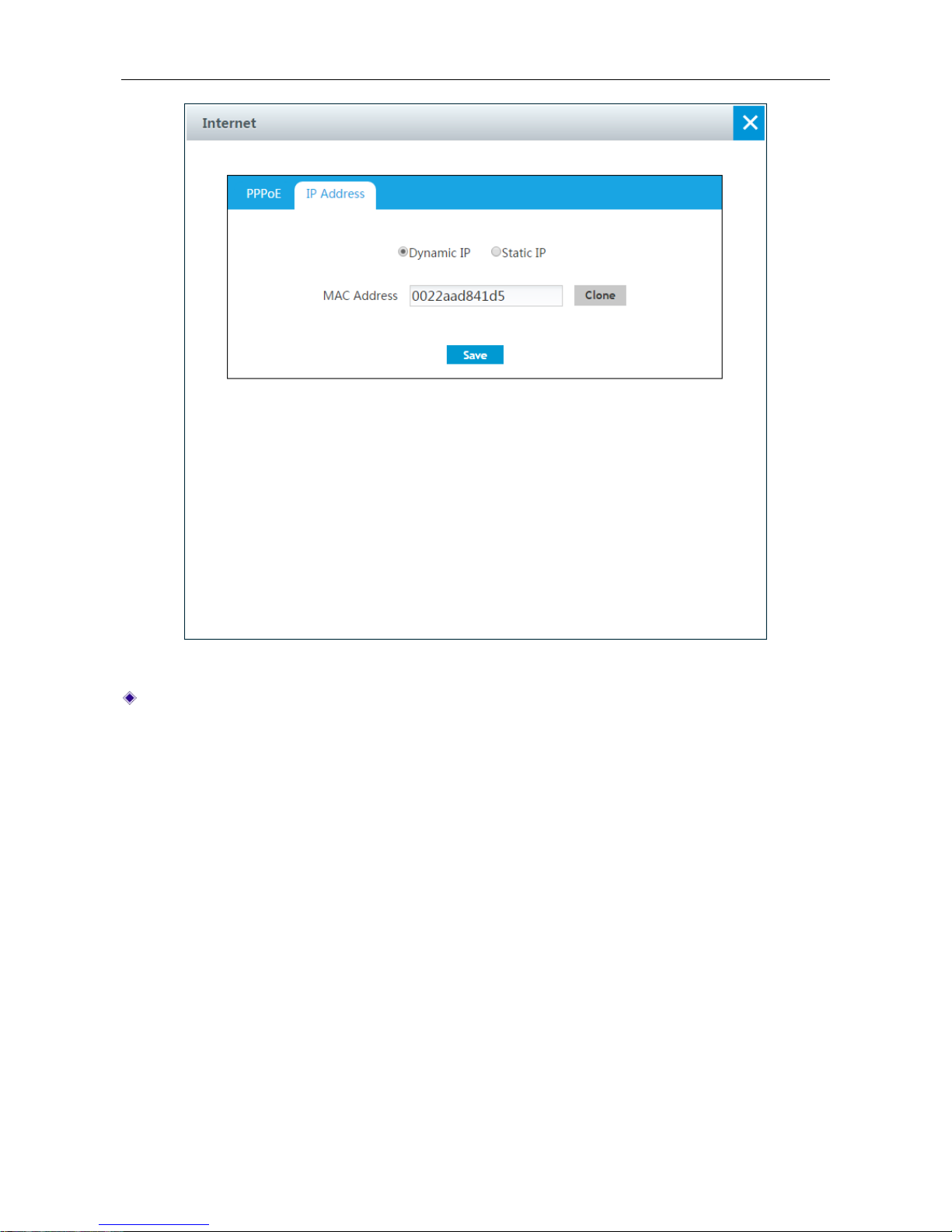
Figure 4-10 Dynamic IP Connection setting
MAC Address: Displays the device’s physical address. We always keep it as the default value.
4.5.3 Static IP Connection
Some infrastructure situations have to use static address, such as finding the Domain Name
System (DNS) host where it is, the Device will translate domain names to IP addresses. Static
addresses are convenient, but not absolutely necessary, to locate servers inside an enterprise.
If you are required to use a permanent IP address, select Static IP.
Page 36
UTT Technologies Application
http://www.uttglobal.com Page 31
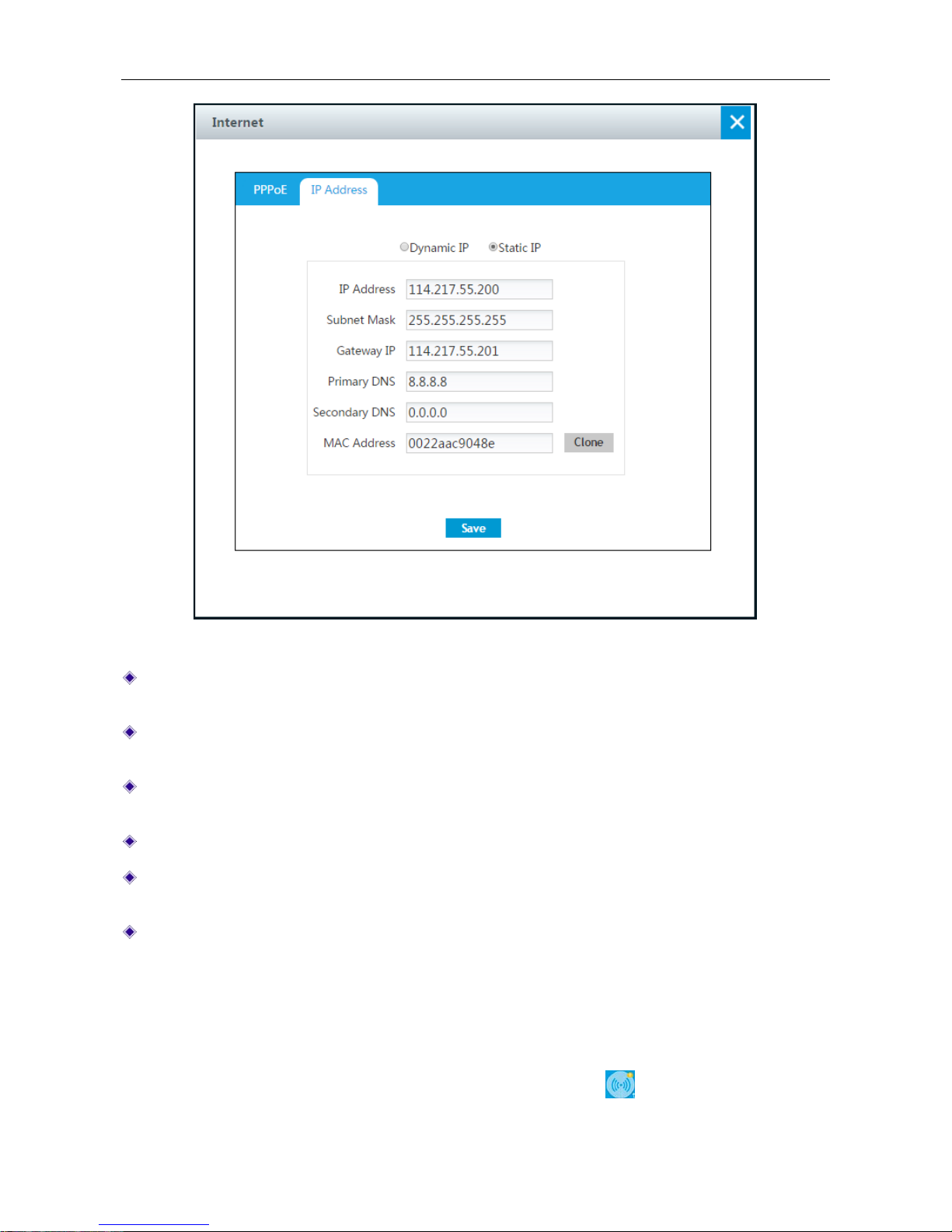
Figure 4-11 Static IP Connection setting
IP Address: Enter the IP address for the Device’s WAN interface, which is provided by your
ISP.
Subnet Mask: Enter the subnet mask for the Device’s WAN interface, which is provided by
your ISP.
Gateway IP Address: Enter the IP address for the default gateway, which is provided by your
ISP.
Primary DNS Server: Enter the IP address of your ISP’s primary DNS server.
Secondary DNS Server: Enter the IP address of your ISP’s secondary DNS server if it is
available.
MAC Address: Displays the device’s physical address. We always keep it as the default value.
4.6 Wireless
This chapter describes how to configure and use the wireless features of the Device. The Device
supports 2.4GHz wireless and 5GHz wireless (only for dual-band wireless router). We can access
Wireless application by clicking Application > Wireless or clicking
at homepage.
Page 37
UTT Technologies Application
http://www.uttglobal.com Page 32
4.6.1 2.4GHz Wireless
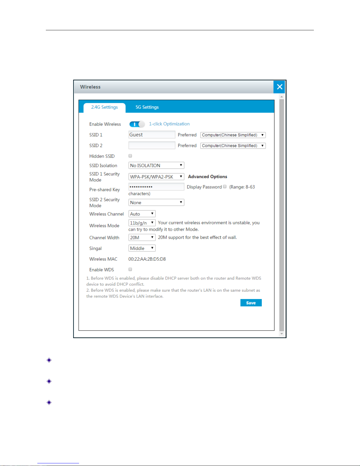
On Application > Wireless > 2.4G Settings page, we can set 2.4GHz wireless parameters ,
including SSID, Security mode, wireless channel, wireless mode, channel width and so on.
Figure 4-12 2.4GHz wireless setting
Enable Wireless: Click to open 2.4GHz Wireless network. When the wireless network is bad,
you can click 1-click Optimization to optimize the network.
SSID 1 or SSID 2: The SSID (Serv ice Set Identification) is also known as the wireless network
name, which is used to uniquely identify a wireless network.
Hidden SSID: Select to hide SSID. In this case, if users want to access thi s network, they
need to search for SSID by entering it manually.
Page 38
UTT Technologies Application
http://www.uttglobal.com Page 33
SSID ISOLATION: Select the SSID you want to isolate from the drop-down box, available
options are No ISOLATION, ISOLATE SSID1 and ISOLATE SSID2.
No ISOLATION: if selected, all users connected to the Device can access to the Device.
ISOLATE SSID1: if selected, the users connected to SSID 1 couldn’t access to the Device.
ISOLATE SSID2: if selected, the users connected to SSID 2 couldn’t access to the Device.
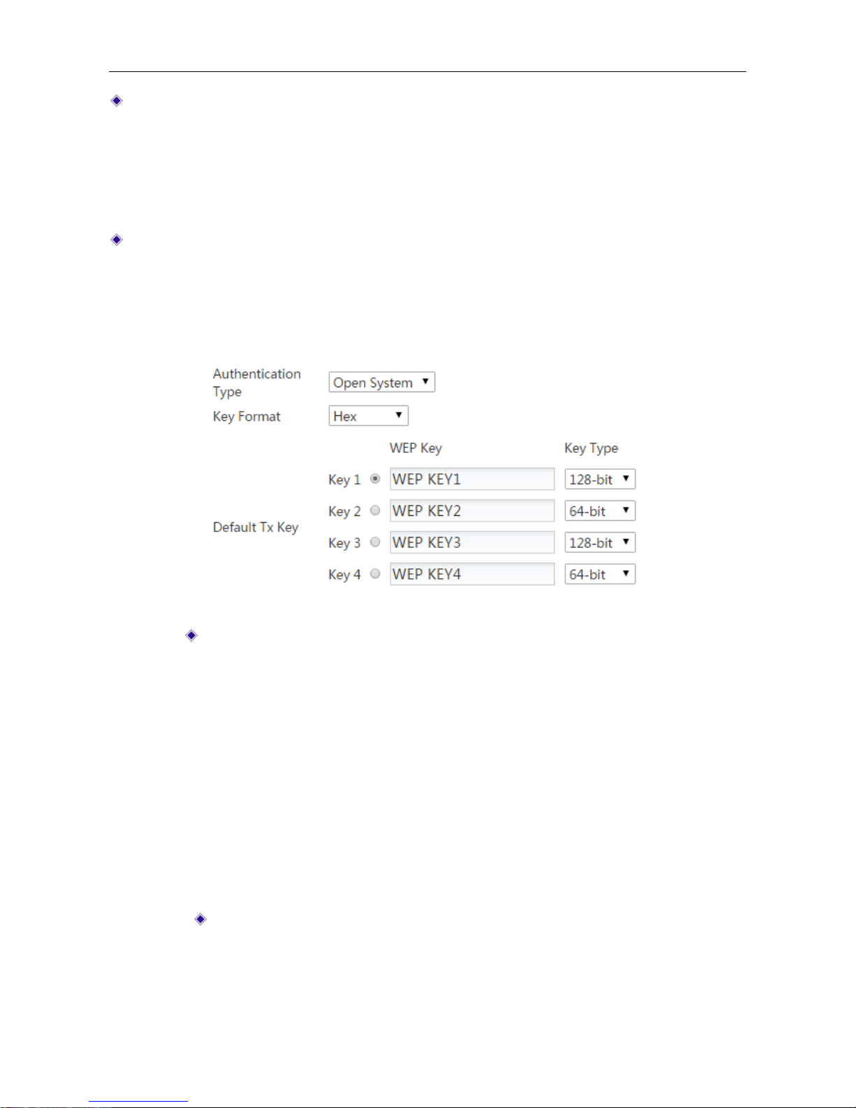
SSID1 Security : Select the security mode you want to use for SSID 1 from the drop-down box,
available security mode options are None, WEP, and WPA-PSK/WPA2-PSK.
1) None: If you want an open network without wireless security, keep the default value of
None.
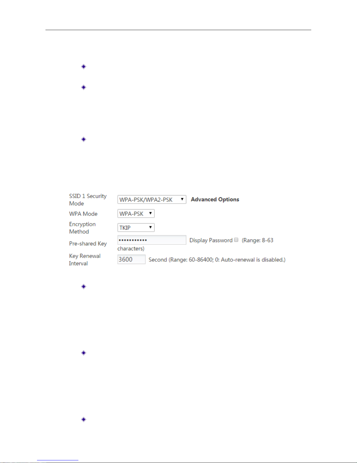
2) WEP: WEP is the basic encryption mode which is not as secure as WPA.
Figure 4-13 Security mode_WEP
Authentication Type: Select the authentication type under WEP security mode.
The Device must authenticate a wireless client before the client can join the
wireless network. There are three options: Auto, Open System and Shared Key.
Auto: Select to allow the Device automatically choose Open System or
Shared key mode according to the requests of wireless clients.
Open System: At this point, the wireless client host can pass the
authentication and be associate with the wireless devices on the premise of
providing no authentication key; but a correct key must be provided if data
transmission is to be made.
Shared Key: At this point, the wireless client host must provide the correct
key to pass the authentication; otherwise, it cannot be associated with the
wireless devices, and cannot perform data transmission.
Key Format: Select the format for entering the WEP keys. The options are Hex
and ASCII.
Hex: Select it to enter the WEP keys in hexadecimal format. Hexadecimal
digits are a set of characters that includes numbers 0 through 9 and letters A
through F (or a through f). Hex WEP keys are case insensitive.
Page 39
UTT Technologies Application
http://www.uttglobal.com Page 34
ASCII: Select it to enter the WEP keys in ASCII format. ASCII W EP keys are
case sensitive.
Default Tx Key: Select one of the WEP keys as the default transmit key to
transmit data. All keys can be used to receive data.
WEP Key: Enter a key in one of the WEP Key boxes. You can enter up to four
WEP keys. You should enter a key according to the Key Format and Key Type
selected.
For 64-bit encryption, enter 10 hex characters or 5 ASCII characters.
For 128-bit encryption, enter 26 hex characters or 13 ASCII characters.
Key Type: Select the size of each key, and it also allows you to disable or enable
each key. The options are Disabled, 64-bit and 128-bit. By default, Disabled is
selected, which means the key is of no effect.
3) WPA-PSK/WPA2-PSK: This mode intends for the wireless network that doesn’t have a
RADIUS server. In this mode, the Device uses the pre-shared key that is manually entered
to generate encryption keys.
Figure 4-14 Security mode_ WPA-PSK/WPA2-PSK
WPA Mode: Select the WPA mode you want to use. The options are Auto,
WPA-PSK and WPA2-PSK.
Auto: If selected, the Device can automatically choose WPA or WPA2
security mode according to the requests of wireless clients.
WPA-PSK: If selected, the Device will use the security mode of WPA-PSK.
WPA2-PSK: If selected, the Device will use the security mode of WPA2-PSK.
Encrption Method: Select the encrytion method you want to use. The options are
Auto, TKIP and AES.
Auto: If selected, the Device automatically choose encryption method for
each wireless client.
TKIP: If selected, the Device will use TKIP for data encryption.
AES: If selected, the Device will use AES for data encryption.
Pre-shared Key: The preset initialization key, with the value of 8 ~ 63 characters.
Page 40

UTT Technologies Application
http://www.uttglobal.com Page 35
Key Renewal Interval: Specify how often (in seconds) the WPA group key
changes. The valid range is 60-86400 or 0, and the default is 3600. Enter 0 to
disable automatic renewal.
SSID2 Security: Select the security mode you want to use for SSID 2.
Wireless Channel: Select the frequency bands in which the wireless network works; it
provides automatic options, which means that the Device can automatically select the optimal
frequency band. The wireless devices in the same frequency band will interfere with each other.
If there are multiple wireless devices around the Device, please select a frequency band
different from that of other wireless devices when setting the channel.
Wireless Mode: Specify the wireless modes of the Device. The options are 11g Only, 11n
Only and 11b/g/n Mixed.
● 11g Only: Pure 802.11g mode, in which the maximum rate is up to 54Mbps. The wireless
clients in compliance with the IEEE 802.11g standard can be connected to the Device.
● 11n Only: Pure 802.11n mode, in which the maximum rate is up to 300Mbps. The wireless
clients in compliance with the IEEE 802.11n standard can be connected to the Device.
● 11b/g/n Mixed: The wireless clients in compliance with IEEE 802.11b, 802.11g or 802.11n
standard will be connected according to their wireless modes, with the maximum rates of
11M bps, 54M bps and 300M bps respectively.
● 11g/n: The wireless clients in compliance with IEEE 802.11g or 802.11n standard will be
connected according to their wireless modes, with the maximum rates of 5 4M bps and 300M
bps respectively.
Channel Width: The channel bandwidth occupied by the wireless data transmission, with the
options: Auto, 20M and 40M. Note that this parameter works only with the wireless clients
accessed using the 802.11n standard; for those using the 802.11b or 802.11g standard, only
the channel bandwidth of 20M can be used:
● Auto: If selected, the wireless clients accessed using the 802.11n standard will use the
channel bandwidths of 20M or 40M according to the results of the negotiation with the
accessed peer device.
● 20M: If selected, the wireless clients accessed by using the 802.11g standard will use the
channel bandwidth of 20M.
● 40M: If selected, the wireless clients accessed by using the 802.11n standard will use the
channel bandwidth of 40M.
Signal: Specify the strength of the wireless transmit power.
Wireless MAC: Displays the device’s physical address. We alw ays keep it as the default value.
Enable WDS: Select to enable WDS. It can be bridging multiple wireless LAN by this function.
About more information, please refer to section:
4.6.3 WDS Configuration Example
4.6.2 5GHz wireless
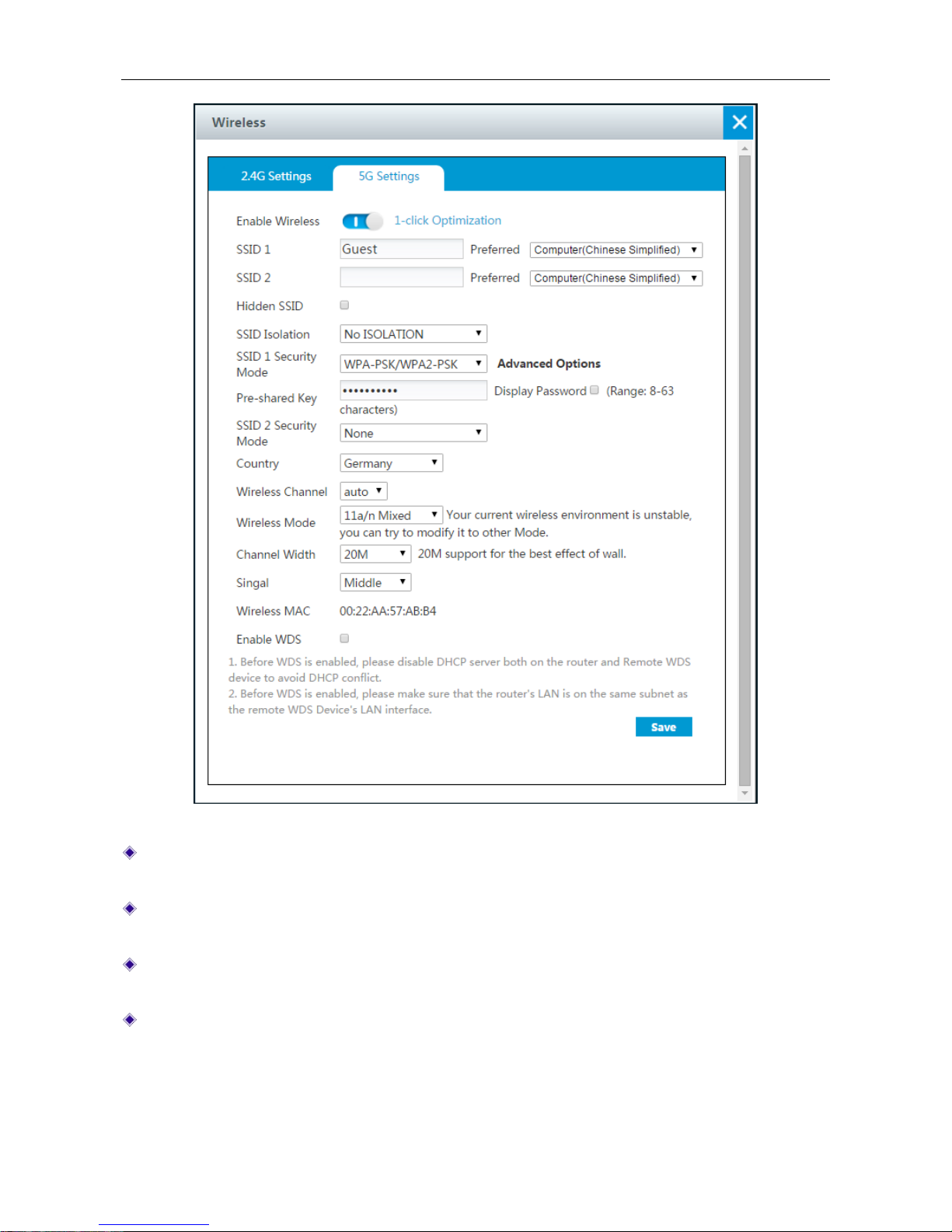
On Application > Wireless > 5G Settings page, we can set 5GHz wireless parameters , including
SSID, Security mode, wireless channel, wireless mode, channel width and so on.
Page 41
UTT Technologies Application
http://www.uttglobal.com Page 36
Figure 4-15 2.4GHz wireless setting
Enable Wireless: Click to enable 5GHz Wireless network. When the wireless network is bad,
you can click 1-click Opt imization to optimize the network.
SSID 1 or SSID 2: The SSID (Service Set Identification) is also known as the wireless network
name, which is used to uniquely identify a wireless network.
Hidden SSID: Select to hidden SSID. In this case, if users want to access this network, they
need to search for SSID by entering it manually.
SSID ISOLATION: Select the SSID you want to isolate from the drop-down box, available
options are No ISOLATION, ISOLATE SSID1 and ISOLATE SSID2.
No ISOLATION: if selected, all users connected to the Device can access to the Device.
ISOLATE SSID1: if selected, the users connected to SSID 1 couldn’t acces s to the Device.
Page 42
UTT Technologies Application
http://www.uttglobal.com Page 37
ISOLATE SSID2: if selected, the users connected to SSID 2 couldn’ t acces s to the Device.
SSID1 Security : Select the security mode you want to use for SSID 1 from the drop-down box,
available security mode options are None, WEP, and WPA-PSK/WPA2-PSK.
1) None: In the None security mode, the client can access to the network without using any
security authentication.
2) WEP: WEP is the basic encryption mode which is not as secure as WPA.
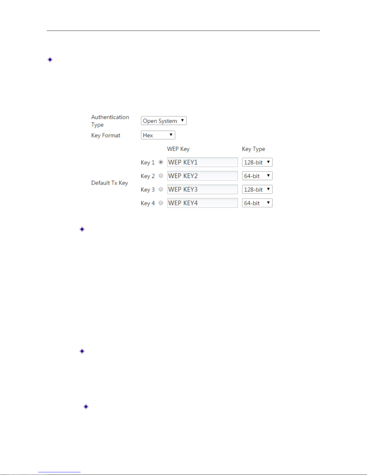
Figure 4-16 Security mode_WEP
Authentication Type: Select the authentication type under WEP security mode.
The Device must authenticate a wireless client before the client can join the
wireless network. The available options are Auto, Open System and Shared Key.
Auto: Select to allow the Device automatically choose Open System or
Shared key mode according to the requests of wireless clients.
Open System: At this point, the wireless client host can pass the
authentication and be associate with the wireless devices on the premise of
providing no authentication key; but a correct key must be provided if data
transmission is to be made.
Shared Key: At this point, the wireless client host must provide the correct
key to pass the authentication; otherwise, it cannot be associated with the
wireless devices, and cannot perform data transmission.
Key Format: Two formats Hex (hexadecimal code) and ASCII (ASCII code) are
provided:
When the hexadecimal code is used, the key characters can be 0 ~ 9, A, B, C ,
D, E, F.
When the ASCII code is used, the key characters can be all ASCII codes.
Default Tx Key: Select one of the WEP keys as the default transmit key to
transmit data. All keys can be used to receive data.
Page 43
UTT Technologies Application
http://www.uttglobal.com Page 38
WEP Key: Enter a key in one of the WEP Key boxes. You can enter up to four
WEP keys. You should enter a key according to the Key Format and Key Type
selected.
For 64-bit encryption, enter 10 hex characters or 5 ASCII characters.
For 128-bit encryption, enter 26 hex characters or 13 ASCII characters.
Key Type: Select the key types. There provides three options: Disabled, 64-bits,
128-bits. Among them, Disabled means not to use the current key, but 64-bits,
128-bits are used to specify the length of the WEP key.
3) WPA-PSK/WPA2-PSK: This mode intends for the wireless network that doesn’t have a
RADIUS server. In this mode, the Device uses the pre-shared key that is manulally entered
to generate encryption keys.
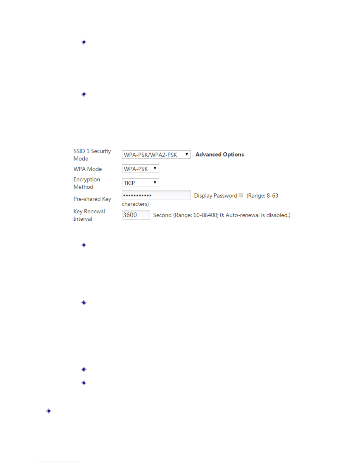
Figure 4-17 Security mode_ WPA-PSK/WPA2-PSK
WPA Mode: Select the WPA mode you want to use. The options are Auto,
WPA-PSK and WPA2-PSK.
Auto: Select to allow both WPA and WPA2 clients to connect to the Device.
WPA-PSK: Select to only allow WPA clients to connect to the Device.
WPA2-PSK: Select to only allow WPA2 clients to connect to the Device.
Encrption Method: Select the encrytion method you want to use. The options are
Auto, TKIP and AES.
Auto: The Device automatically choose encryption method for each wireless
client.
TKIP: The Device will use TKIP for data encryption.
AES: The Device will use AES for data encryption.
Pre-shared Key: The preset initialization key, with the value of 8 ~ 63 characters.
Key Renewal Interval: Specify how often (in seconds) the WPA group key
changes. The valid range is 60-86400 or 0, and the default is 3600. Enter 0 to
disable automatic renewal.
SSID2 Security: Select the security mode you want to use for SSID 2.
Page 44

UTT Technologies Application
http://www.uttglobal.com Page 39
Country: Select the country the Device resides. Different country support different wireless
channel.
Wireless Channel: Select the frequency bands in which the wireless network works; it
provides automatic options, which means that the Device can automatically select the optimal
frequency band. The wireless devices in the same frequency band will interfere with each other.
If there are multiple wireless devices around the Device, please select a frequency band
different from that of other wireless devices when setting the channel.
Wireless Mode: Specify the wireless modes of the Device. The options are 11a Only, 11a/n
Mixed, 11vht AC/AN/A and 11vht AC/AN.
● 11a Only: If selected, the wireless clients in compliance with the IEEE 802.11a standard
can be connected to the Device.
● 11a/n Mixed: If selected, the wireless clients in compliance with the IEEE 802.11a and
802.11n standard can be connected to the Device.
● 11vht AC/AN/A: Very High Throughput IEEE 802.11ac and 802.11a Standard. If selected,
the wireless clients in compliance with the IEEE 802.11ac and 802.11a standard can be
connected to the Device.
● 11vht AC/AN: Very High Throughput IEEE 802.11ac Standard. If selected, the wireless
clients in compliance with the IEEE 802.11ac standard can be connected to the Device.
Channel Width: The channel bandwidth occupied by the wireless data transmission. It
provides automatic options, which means that the Device can automatically select the optimal
channel bandwidth.
Signal: Specify the strength of the wireless transmit power.
Wireless MAC: Displays the device’s physical address. We alw ays keep it as the default value.
Enable WDS: Select to enable WDS. It can be bridging multiple wireless LAN by this function.
About more information, please refer to section:
5.6.3 WDS Configuration Example
4.6.3 WDS Configuration Example
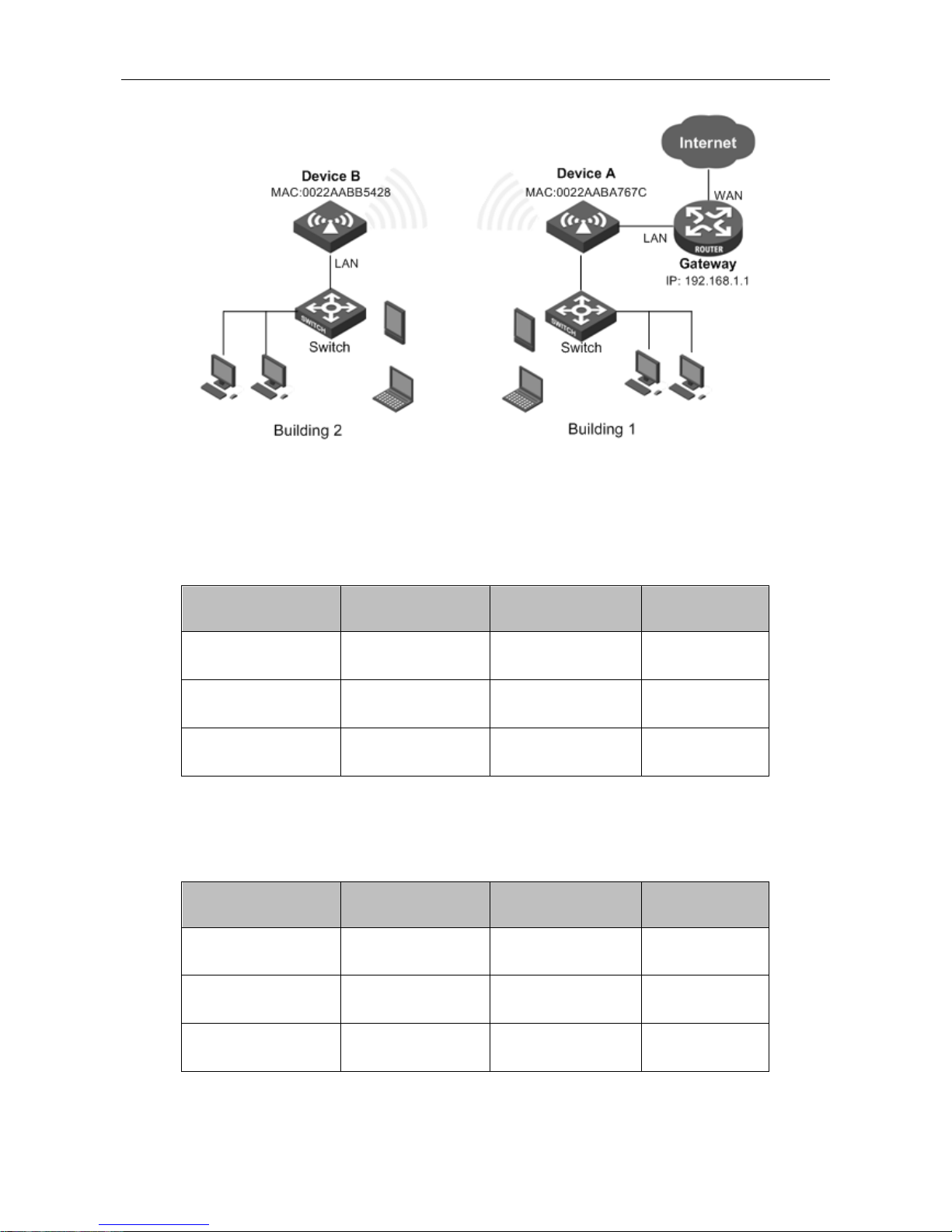
1) Network Requirements
As shown in the following figure, the network uses a wired router as the gateway (IP: 192.168.1.1)
to the Internet, a UTT WA wireless access (denoted as Device A) to connect computers and other
devices in Building 1, and another UTT WA wireless access (denoted as Device B) to connect
computers and other devices in Building 2. Device A is connected to the gateway via an Ethernet
cable, so the client devices connected to Device A can access to the Internet. Now the user wants
to connect Device B to Device A wirelessly, so that the client devices connected to Device B also
can access to the Internet.
Page 45
UTT Technologies Application
http://www.uttglobal.com Page 40
Figure 4-18 Network Topology – WDS Configuration Example
2) Configuration Steps
Steps 1: Login to Device A. Go to Application > Wireless > 2.4G Settings page to set
parameters as the following table.
Parameters Value Parameters Value
SSID 1
UTT_A
Security Mode
None
Wireless Channel 6
Wireless Mode
11b/g/n
Channel Width
40M LAN IP address 192.168.2.2
Table 4-1 The parameters of Device A
Step 2: Login t o Devi ce B, G o to Application > W i rel es s > 2. 4G S ett in gs p ag e t o s et parameters
as following table and go to Application > DHCP Server to disable DHCP Server.
Parameters Value Parameters Value
SSID 1
UTT_B
Security Mode
None
Wireless Channel 6
Wireless Mode
11b/g/n
Channel Width
40M LAN IP address 192.168.2.3
Table 4-2 The parameters of Device B
Page 46
UTT Technologies Application
http://www.uttglobal.com Page 41
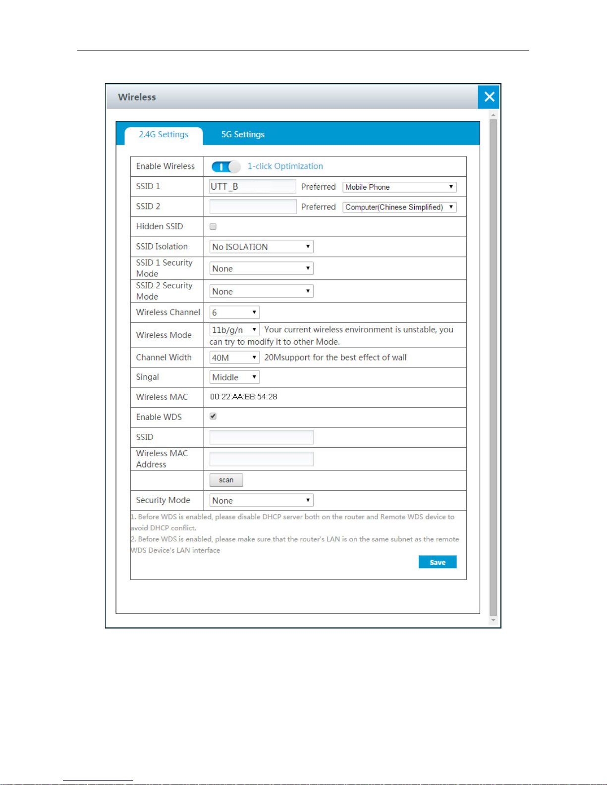
Step 3: Select Enable WDS checkbox on the Device B. As shown in the following figure.
Figure 4-19 WDS bridging
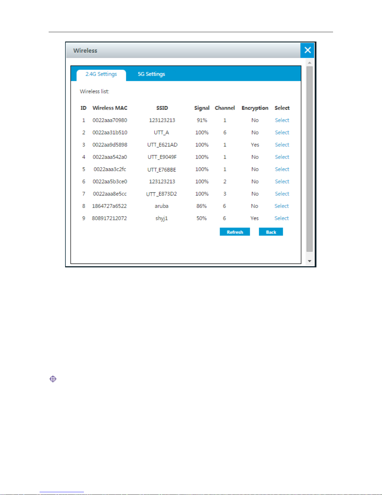
Step 4: Click the scan button to scan the wireless network. Select Device A (SSID is UTT_A) and
click the Save button to save all settings.
Page 47
UTT Technologies Application
http://www.uttglobal.com Page 42
Figure 4-20 Wireless list
Step 5: A few second later, Device B will be connected to Device A successfully.
Step 6: Login to Device A, Do the same procedure from step 3 to step 5 to let Device A connected
to Device B successfully.
Step 7: Verify connectivity between Device A and Device B.
To test connectivity, you can login to a computer that is connected to Device B, and use the ping
command to ping the LAN IP address of the Device A. If ping is successful, a wireless connection
between the two devices has been established.
After Device B is connected to Device A wirelessly, the client devices connected to Device B are
able to access the Internet.
Note:
1) The LAN IP addresses of Device A and Device B must be on the same subnet.
2) The Wireless Mode, Wireless Channel, Channel Width and Security Mode configured on
Device A and Device B must be the same.
3) Before WDS is enabled, please disable DHCP Server on one device to avoid DHCP conflict.
Page 48
UTT Technologies Application
http://www.uttglobal.com Page 43
4.7 LAN
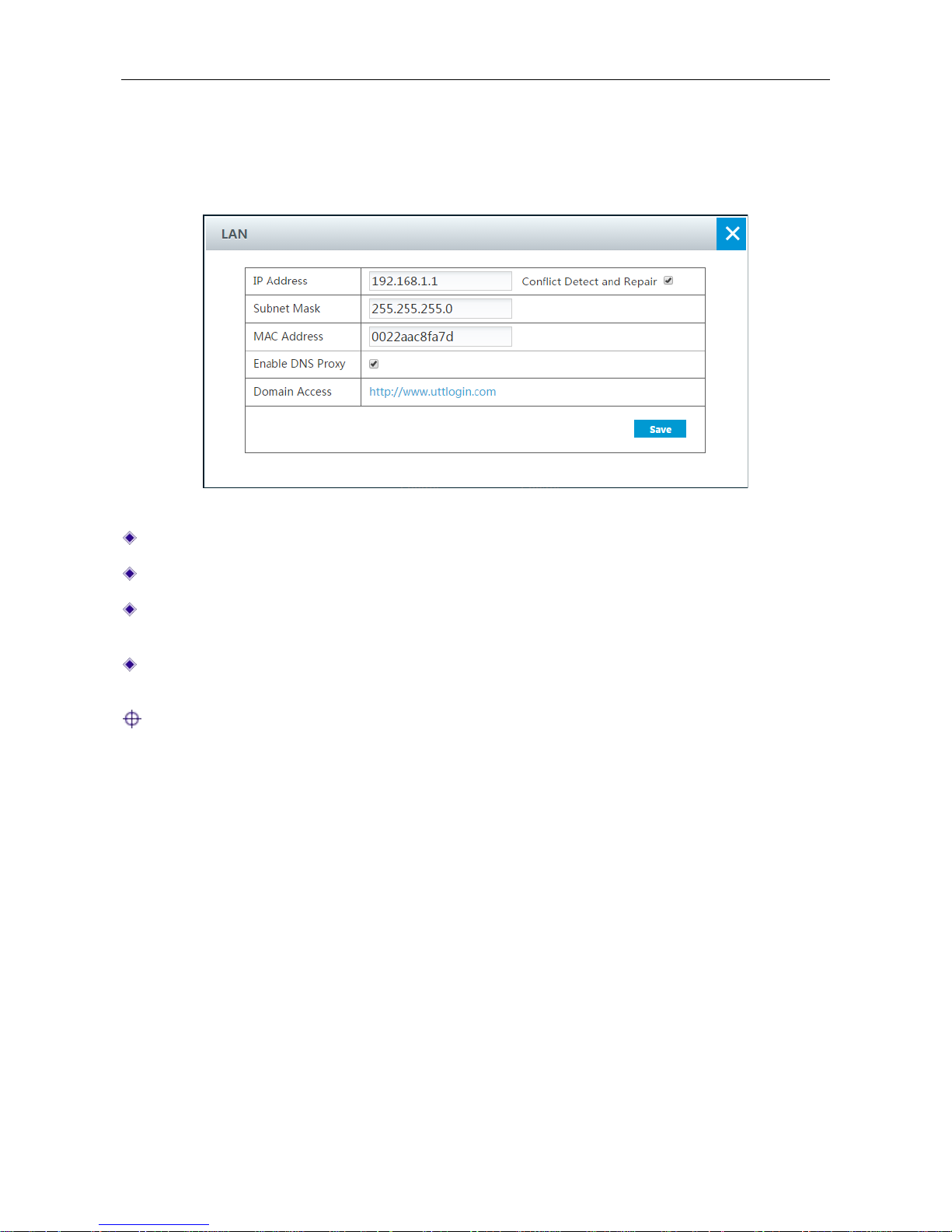
This section describes Application > LAN page. You can set the IP address of the LAN interface
and enable DNS proxy.
Figure 4-21 LAN IP setting
IP Address: Specify the IP address of the LAN interface.
Subnet Mask: Specify the subnet mask that defines the range of the LAN.
MAC Address: The MAC address of the LAN interface. We recommend that you do not
change the default value unless absolutely necessary.
Enable DNS Proxy: If enabled, the Device acts as a proxy for all DNS requests from the LAN
hosts and communicate with the ISP DNS servers.
Note: After modifying the IP address of LAN port, you must use the new IP address to log into
the Device, and the default gateway of each LAN users should use this new address to access
Internet.
4.8 Static Route
A static route is manually configured by the network administrator, which is stored in a routing table.
By using routing table, the Device can select an optimal transmission path for each received pac ket,
and forward the packet to the destination site effectively. The proper usage of static routes will not
only improve the network performance, but also achieve other benefits, such as traffic control,
provide a secure network environment.
The disadvantage of using static routes is that they cannot dynamically adapt to the current
operational state of the network. When there is a change in the network or a failure occurs, some
static routes will be unreachable. In this case, the network administrator should update the static
routes manually.
Page 49
UTT Technologies Application
http://www.uttglobal.com Page 44
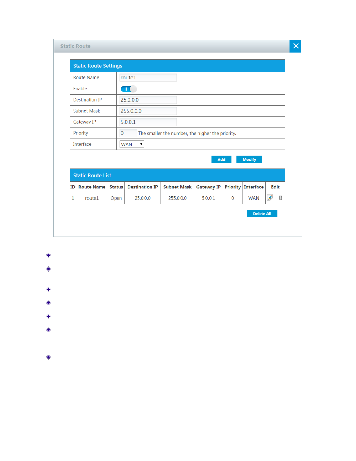
Figure 4-22 Static Route
Route Name: Specify a unique name for the static route.
Enable: Click to enable the static route. To temporarily disable the route instead of deleting it,
clear the check box.
Destination IP: Specify the IP address of the destination network or host.
Subnet Mask: Specify the subnet mask of the destination network or host.
Gateway IP: Specify the IP address of the next hop router to which to forward the packets.
Priority: Specify the priority of the static route. If there are multiple routes to the same
destination with different priorities, the Device will choose the route with the highest priority to
forward the packets. The smaller the number, the higher the priority.
Interface: Specify the outbound interface through which the packets are forwarded to the next
hop gateway or router. The available options are the name of each physical interface.
4.9 UPnP
The Universal Plug and Play (UPnP) is architecture that implements zero configuration networking,
that is, it provides automatic IP configuration and dynamic discovery of the UPnP compatible
Page 50
UTT Technologies Application
http://www.uttglobal.com Page 45
devices from various vendors. An UPnP compatible device can dynamically join a network, obtain
an IP address, announce its name, convey its capabilities upon request, and learn about the
presence and capabilities of other devices on the network.
The Device can implement NAT traversal by enabling UPnP. When you enable UPnP, the Device
allows any LAN UPnP-enabled device to perform a variety of actions, including retrieving the public
IP address, enumerate existing port mappings, and add or remove port mappings. By adding a port
mapping, an UPnP-enabled device opens the related service ports on the Device to allow the
Internet hosts access. Windows Messenger is an example of an application that supports NAT
traversal and UPnP.
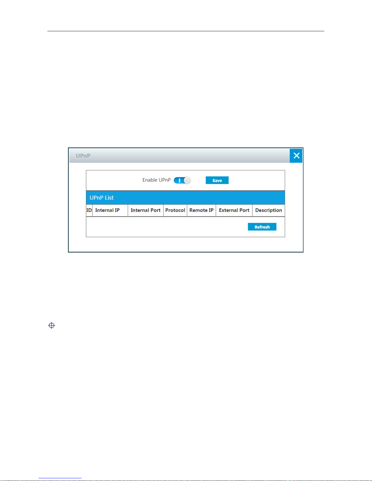
The Device provides
the UPnP List, which li sts all the port forwarding rules established usin g UPnP.
You can view each port forwarding
rule’s detailed information in the list, which includes internal IP
address, internal port, protocol, remote IP address, external port, and description.
Figure 4-23 UPnP
4.10 Bandwidth Control
This section describes Application > Bandwidth Control page. This feature allows you to limit the
maximum upload and download speed for the LAN users.
Notes: It is not suggested to enable Bandwidth Control and Fle xible Bandwidt h at the same
time.
Page 51
UTT Technologies Application
http://www.uttglobal.com Page 46
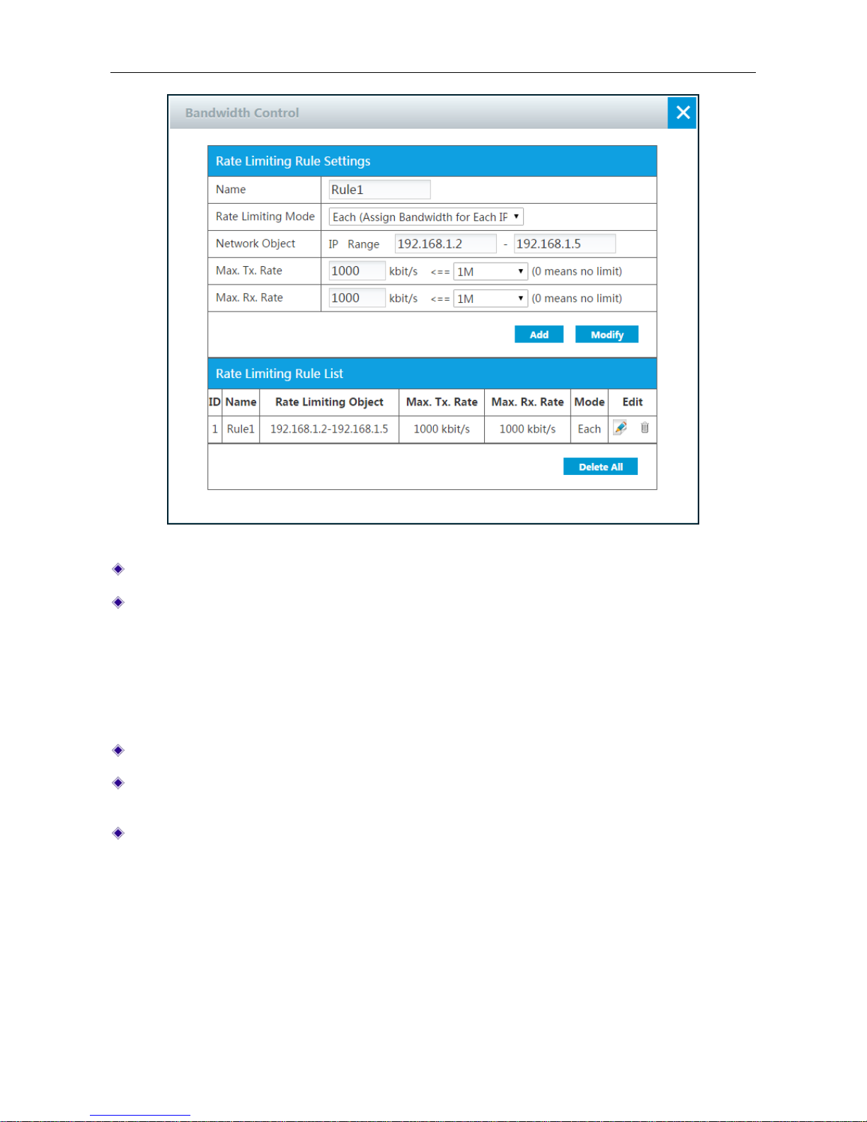
Figure 4-24 Bandwidth Control
Group Name: Specify a unique name for the group to which the fixed rate limiting rule applies.
Rate Limiting Mode: The options are Each, Share and MAC rate limiting.
Each: The specified Max. Tx/Rx Rate is assigned to each member in the group.
Share: The specified Max. Tx/Rx Rate is shared by all members in the group.
MAC rate limiting: The specified MAC address will be limited to the maximum upload and
download speed you set.
Network Object: Specify the range of IP address or the MAC Address.
Max. Tx Rate: Specify the maximum upload speed for the members in the group. The value 0
means unlimited rate.
Max. Rx Rate: Specify the maximum download speed for the members in the group. The value
0 means unlimited rate.
4.11 Parental Control
Parental control is simple, powerful tool to help shield your children from explicit websites and
control the time your children surfing Internet.
Page 52
UTT Technologies Application
http://www.uttglobal.com Page 47
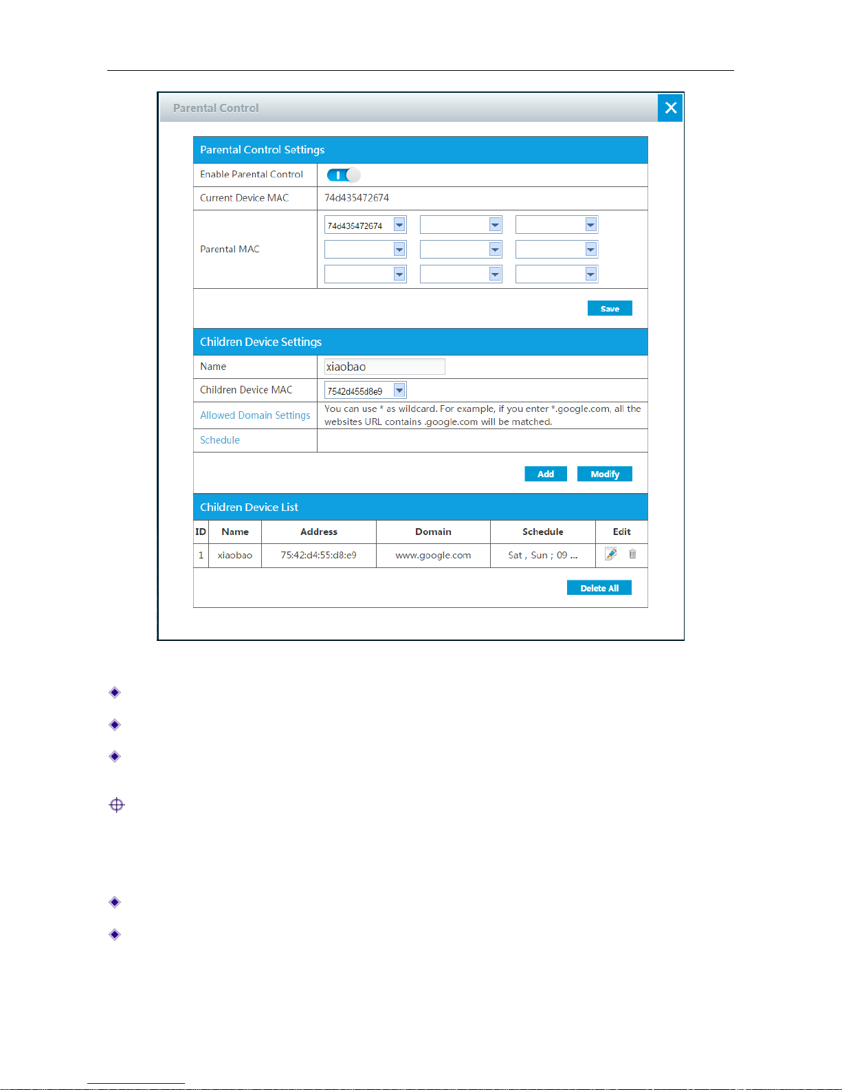
Figure 4-25 Parent Control
Enable Parental Control: Click the button to enable parental control.
Current Device MAC: Displays the current device’s MAC address.
Parental MAC: Specify the parental MAC address which will not be affected by Parental
Control.
Note: After you set Parental Control, parent can access internet but not children and others.
Children Device Settings:
Name: Specify the unique name of this entry.
Children Device MAC: Specify the children MAC address which will be limited to access
internet.
Page 53
UTT Technologies Application
http://www.uttglobal.com Page 48
Allowed Domain Settings: Click the hyperlink to set domains which are allowed children to
access to.
Domains allowed to access: Specify domains which are allowed children to access to.
Schedule: Click the hyperlink to set time that allowed children to access internet.
Effective Date: Specify the date that allowed children to access internet.
Effective Time: Specify the time that allowed children to access internet.
4.12 MAC Filter
This section describes the Application > MAC Filter page. The MAC address filtering is used to
filter the wireless clients based on their MAC addresses. With this feature, you can either allow or
block specific wireless clients to connect to the Device.
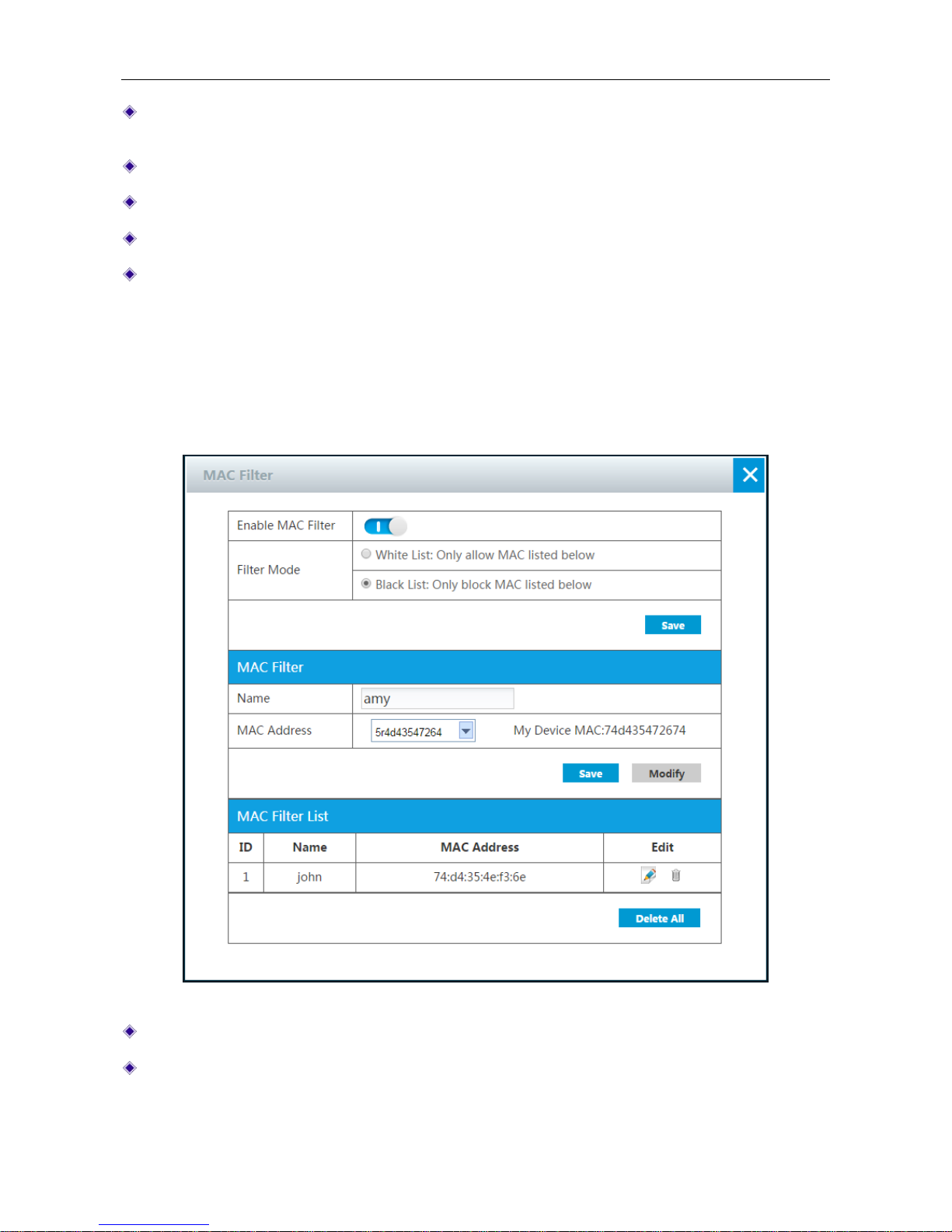
Figure 4-26 MAC Filter
Enable MAC Filter: Select to enable MAC address filtering.
Filtering Mode: Select the mode of MAC address filtering.
Page 54

UTT Technologies Application
http://www.uttglobal.com Page 49
White List: Only allow MAC listed below: If selected, the wireless clients with MAC
address listed in MAC Filter List will be allowed to connect the Device, but block all other
wireless clients.
Black List: Only block MAC listed below: If selected, the wireless clients with MAC
address listed in MAC Filter List will be blocked to connect the Device, but allow all other
wireless clients.
MAC Filter: you can add new MAC address filtering entry to the list.
Name: Specify the name of this MAC Filter.
MAC Address: Specify the MAC address of this MAC Filter.
MAC Filter List: Displays all the MAC Filter entry you have set.
4.13 Virtual Server
By default, the Device blocks all the requests initiated from outside users. In some cases, the
outside users want to access the LAN internal servers through the Device. To achieve this purpose,
you need to create virtual server rules.
Virtual server allows you to create the mapping between <external IP address: external port> and
<internal IP address: internal port>, then all the requests from outside users to the specified
external IP address: port on the Device will be forwarded to the mapped internal server, so the
outside users can access the service offered by the server.
Virtual Server entries take priority over the DMZ host. When receiving a request packet initiated
from an outside user, the Device will first search the Virtual Server List to find out if there is a port
forwarding entry matching the destination IP address and port of the packet. If a match is found, the
Device will forward the packet to the mapped local computer. Else, the Device will try to find out if
there is an available DMZ host.
Page 55
UTT Technologies Application
http://www.uttglobal.com Page 50
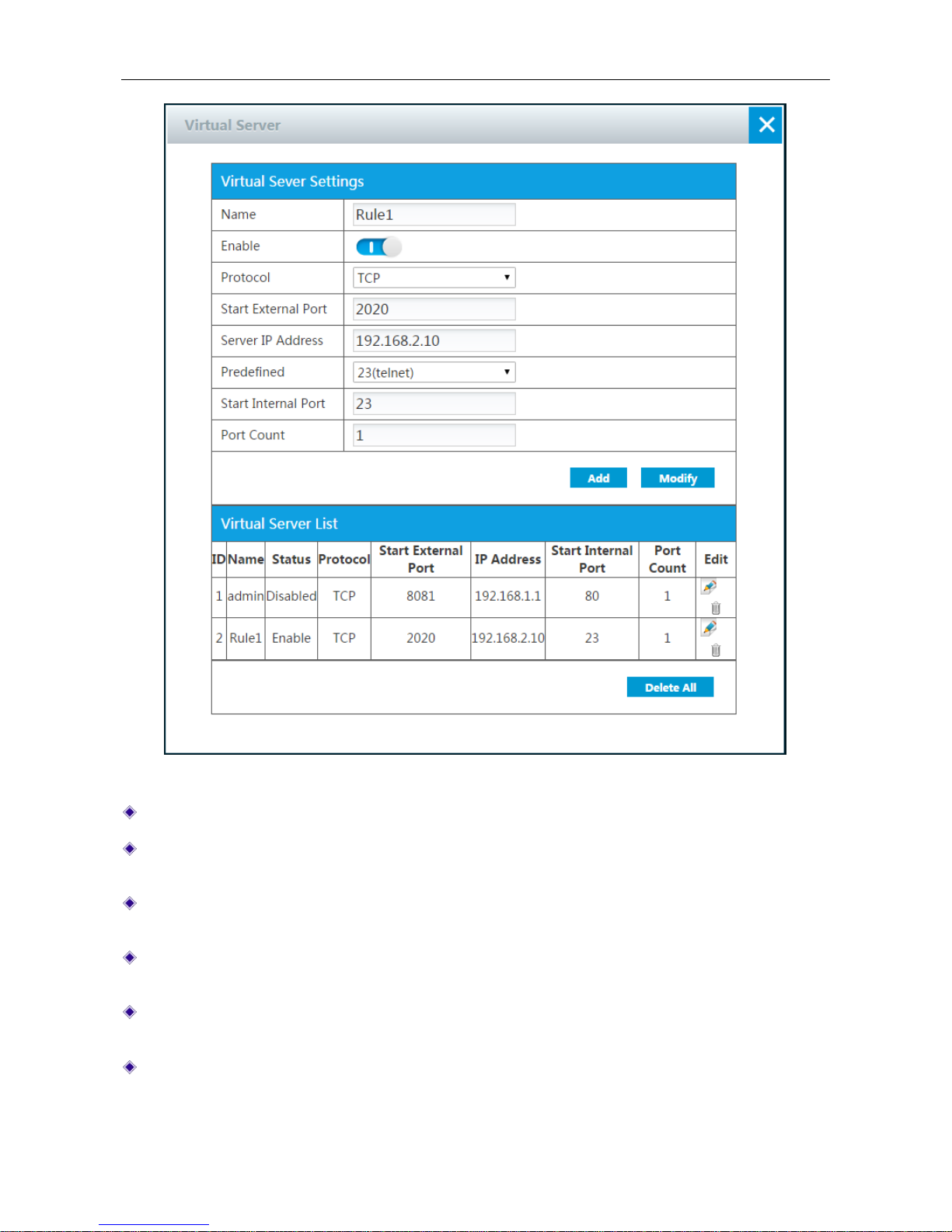
Figure 4-27 Virtual Server
Name: Specify the name of this entry.
Enable: Click to enable this entry. If you keep it disable, this entry will not take effect, only save
it on the Virtual Server List.
Protocol: Specify the transport protocol used by the service. The available options are TCP,
UDP and TCP/UDP.
Start External Port: Specify the low est port numb er provided by the Device. The exte rnal ports
are opened for outside users to access.
Server IP Address: Specify the IP address of the local server that you want outside users to
access.
Predefined: List some common used port. You can select one port as the Start Internal Port.
Page 56
UTT Technologies Application
http://www.uttglobal.com Page 51
Start Internal Port: Specify the lowest port number of the service provided by the LAN host.
The Start External Port and Start Internal Port can be different.
Port Count: Specify the number of ports used by the service. If the service uses only one port
number, enter 1. For example, if the start internal port is 21, the start external port is 2001 and
the port count is 10, then the internal port range is from 21 to 30, and the external port range is
from 2001 to 2010.
4.14 DMZ Host
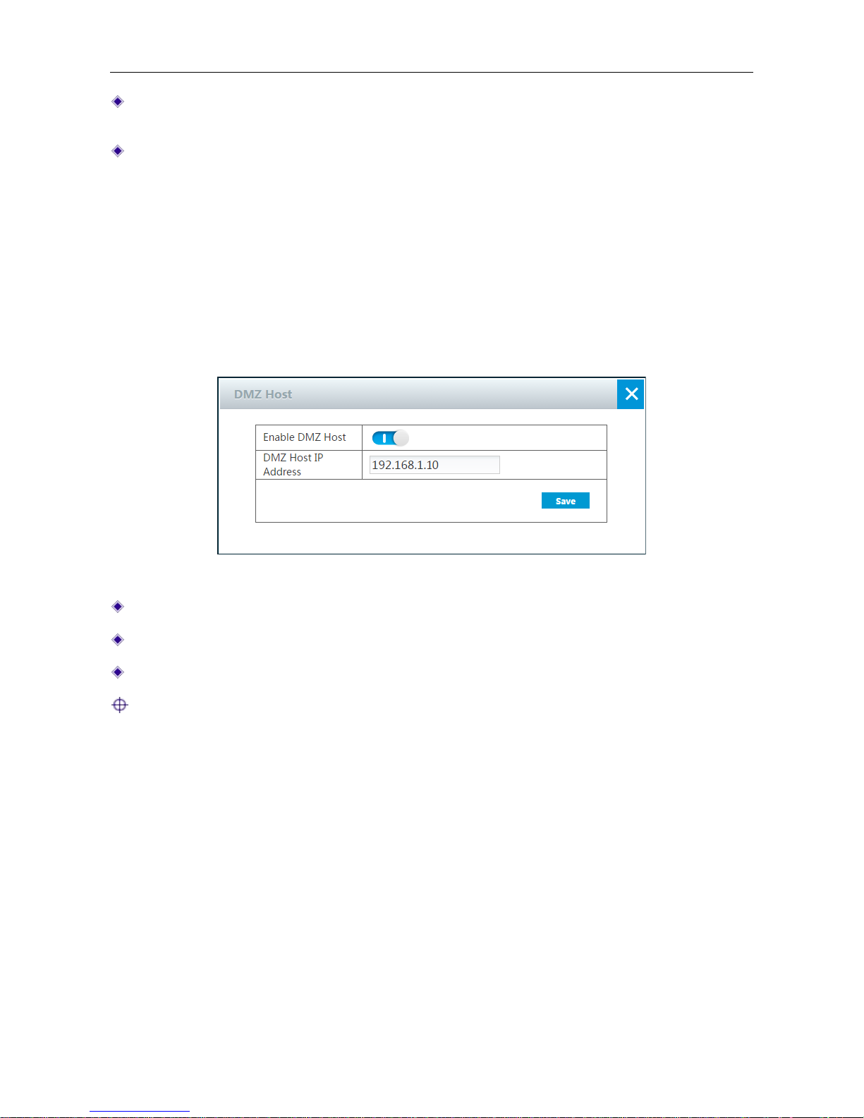
The DMZ (Demilitarized Zone) feature allows one local computer to be exposed to the Internet for
the use of a special service such as online game or video conferencing. When receiving the
requests initiated from outside users, the Device will directly forward these requests to the specified
DMZ host.
Figure 4-28 DMZ Host
Enable DMZ Host: Click to enable DMZ Host.
DMZ Host IP Address: Specify the private IP address of the DMZ host.
Save: Click to save the DMZ host settings.
Note:
The computer designated as the DMZ host will lose firewall protection provided by the Device. As
the DMZ host is exposed to many exploits from the Internet, it may be used to attack your network.
4.15 User Status
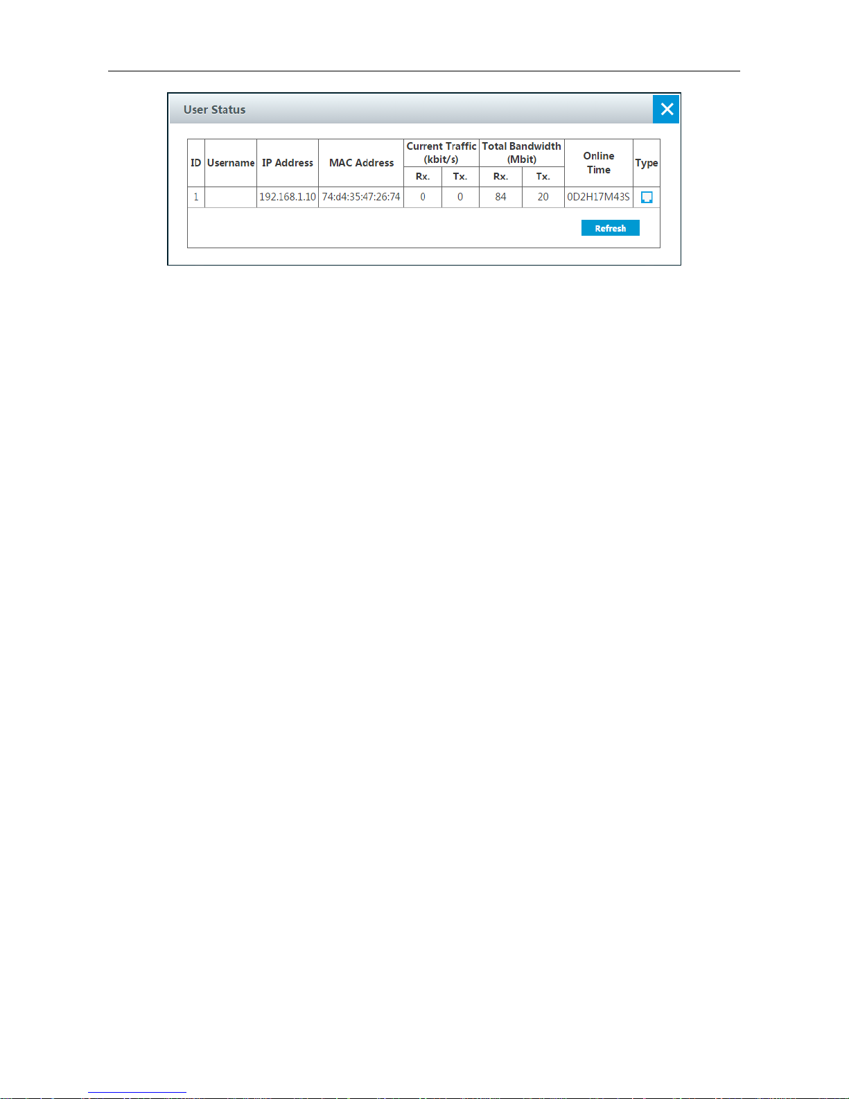
On the Application > User Status page, you can view current status of each user who have
connected to the route, including IP address, MAC address, Rx/Tx rate, Rx/Tx total traffic, online
time and type.
Page 57
UTT Technologies Application
http://www.uttglobal.com Page 52
Figure 4-29 User Status
4.16 System Status
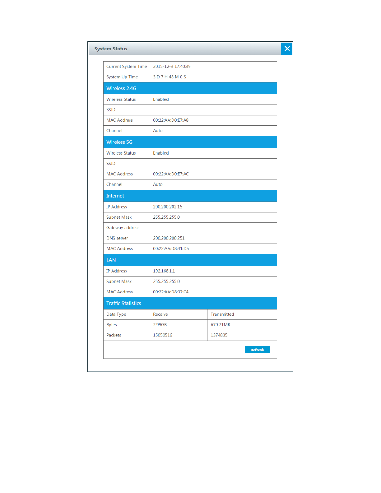
On the Application > System Status page, you can view the system status in detail. Such as
current system time, system up time, 2.4GHz wireless network, 5GHz wireless network, WAN, LAN,
traffic stati s tics and so on.
Page 58
UTT Technologies Application
http://www.uttglobal.com Page 53
Figure 4-30 System Status
4.17 WiFi Auto On/Off
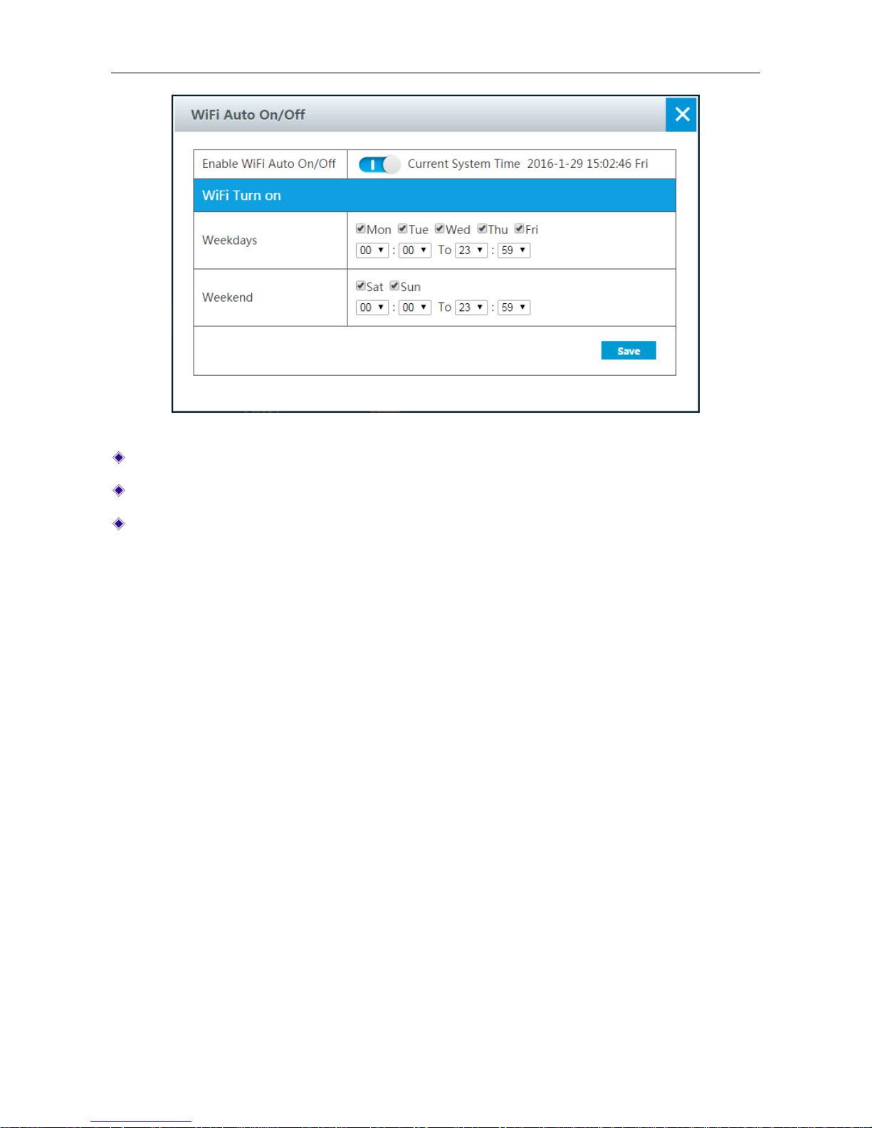
On the Application > WiFi Auto On/Off page, y ou can set the time of WiFi turning on.
Page 59
UTT Technologies Application
http://www.uttglobal.com Page 54
Figure 4-31 WiFi Auto On/Off
Enable WiFi Auto On/Off: Click the button to enable WiFi Auto On/Off.
Weekdays: Specify weekdays’ time of WiFi turning on.
Weekend: Specify weekend’ time of WiFi turning on.
4.18 Time
Lots of features need accurate system date and time to function properly.
You can manually configure the system time or enable SNTP (Synchronize with SNTP Server) to
automatically synchronize the system time from a designated SNTP server on the Internet. It is
suggested that you choose SNTP to automatically synchronize time in most cases.
Page 60
UTT Technologies Application
http://www.uttglobal.com Page 55
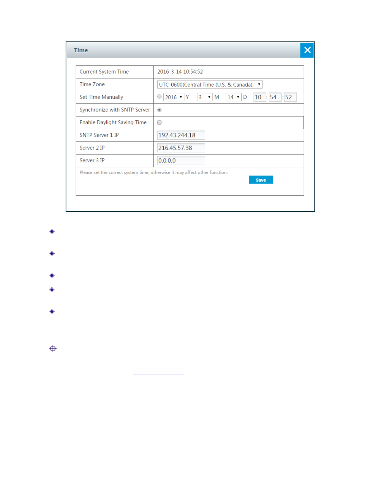
Figure 4-32 Time Setting
Current System Time: Displays the current system date (YYYY-MM-DD) and time
(HH:MM:SS) of the Device.
Time Zone: Select the correct time zone the Device resides. To ensure that the Device gets
the correct time from an SNTP server, you should select the correct time zone.
Set Time Manually: Select to set the date and time (HH:MM:SS) for the Device manually.
Synchronize with SNTP Server: Select to automatically synchronize the system clock from a
designated SNTP server on the Internet.
SNTP Server 1 IP Address ~ Server 3 IP Address: You can configure up to three SNTP
servers on the Device. The Server 1 is the primary server (default is 192.43.244.18), and
Server 2 is the first backup server (default is 216.45.57.38), and the Server 3 is the second
backup server (default is 0.0.0.0). In most cases, we recommend that you do not change them.
Note:
For more information about SNTP, or to find an SNTP server with which you can synchronize the
system clock, please refer to
http://www.ntp.org.
4.19 Remote Management
On the Application > Remot e Management page, you can enable remote management, which
allows you to access the Device’s Web UI from anywhere over the Internet.
Page 61
UTT Technologies Application
http://www.uttglobal.com Page 56
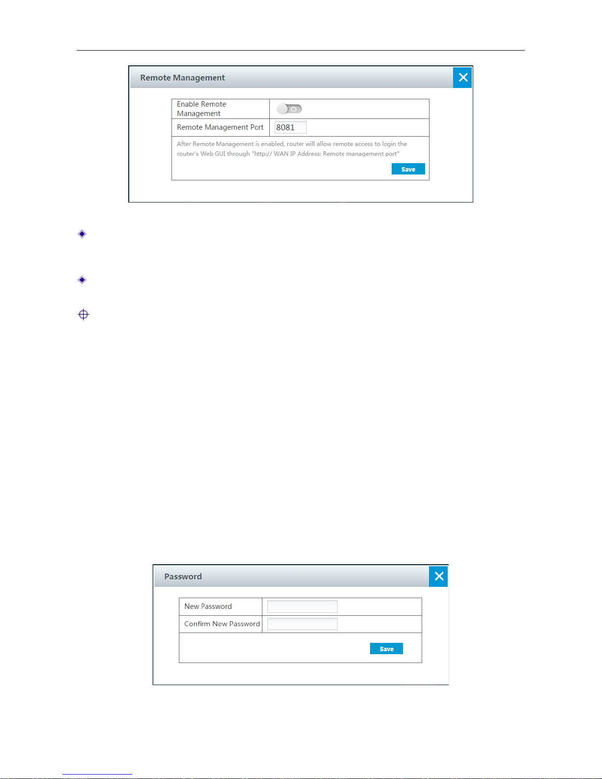
Figure 4-33 Remote Management
Enable Remote Management: Click to enable remote management via Internet. To access
the Device over the Internet, launch a web browser, enter http:// and the WAN IP address of
the Device, followed by a colon and the port number, e.g., http://218.21.31.3:8081..
Remote Management Port: Specify the port number that will be open to outside access. The
default value is 8081.
Note:
1) You can find the Device’s WAN IP address from the Internet List in Application > System
Status page.
2) To ensure security, it is strongly recommended that you do not enable remote management
unless necessary. If you are sure to enable it, you had better go to the Application >
Password page to change the default password.
3) If the Internet connection has a dynamic IP address, you had better enable DDNS in the
Application > DDNS page, so you may use a fixed domain name to manage the Device via
Internet.
4) Please enable the remote management before asking a UTT customer engineer for the
technical support.
4.20 Password
On the Application > Password page, you can modify the login password.
Figure 4-34 Password setting
Page 62
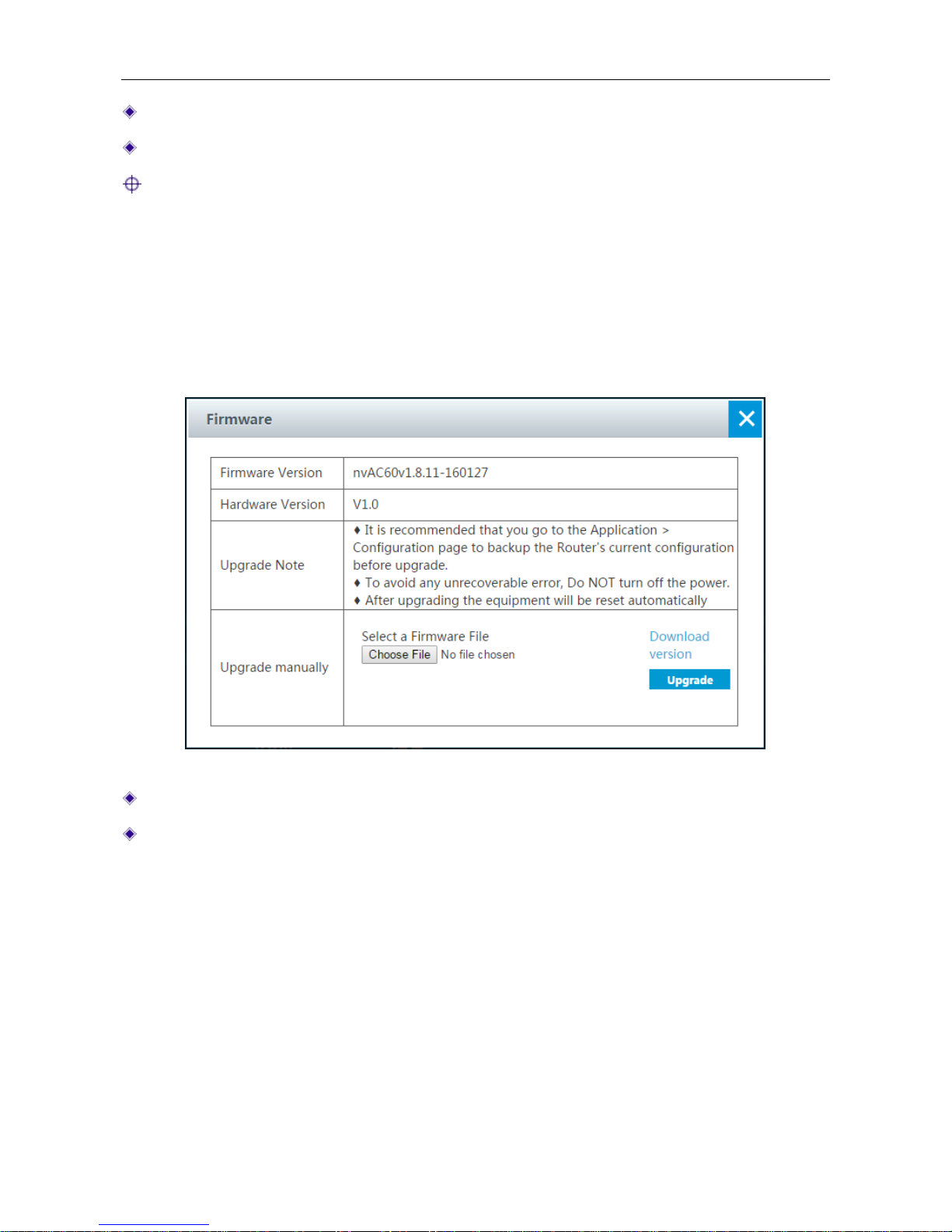
UTT Technologies Application
http://www.uttglobal.com Page 57
Password: Specify a password for the account. The password is case sensitive.
Confirm New Password: Enter the password again to confirm it.
Note:
To ensure security, it is strongly recommended that you change the default administrator passw ord,
remember your new password and keep it safe.
4.21 Firmware
On the Application > Firmware page, you can view the current firmware version information,
download the latest firmware from the UTT website, and upgrade the firmware.
Figure 4-35 Firmware setting
Firmware Version: Displays the current firmware version of the Device.
Hardware Version: Displays the current hardware version of the Device.
To upgrade the Device’s firmware, follow these steps:
1) Download the firmwar e
Click the Download version hyperlink to download the latest firmware from the UTT website.
2) Choose the firmware
Click the Choose File button to locate and select the firmware you want to upgrade.
3) Upgrade the firmware
Page 63
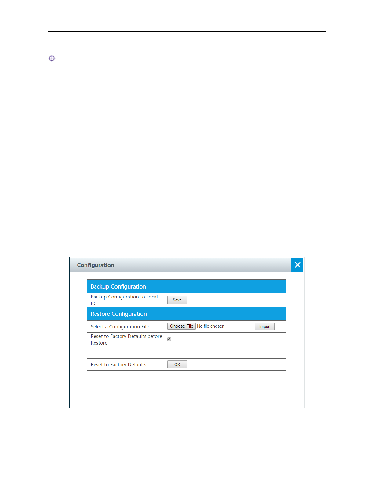
UTT Technologies Application
http://www.uttglobal.com Page 58
Click the Upgrade button. In the pop-up window appears, click OK to start the upgrade.
Note:
1) As new versions of the Device’s firmware become available, you can upgrade the firmware on
your Device to take advantage of new features and improved performance.
2) Please download the firmware that matches the model and hardware version of your Device.
3) It is recommended that you go to Application > Configuration page to backup the Device’s
current configuration before upgrade. Normally, the upgrade does not affect the current
configuration of th e Device. However, this situation might happen if the right steps are not
followed properly.
4) It is strongly recommended that you upgrade the firmware when the Device is under light load.
5) During the firmware upgrade, DO NOT power off the Devi ce, press the Reset button, shut dow n
the PC, or interrupt the process in any way until the operation is complete. Doing so may cause
unexpected error or even irreparable hardware damage.
6) After the upgrade is complete, the Device will automatically restart for the new firmware to take
effect, without human intervention.
4.22 Configuration
On the Application > Configuration page, you can back up the current configuration file to your
local PC, import the configuration file to the Device, and reset the Device to factory default settings.
Figure 4-36 Configuration
1) Backup Configuration File
Page 64

UTT Technologies Application
http://www.uttglobal.com Page 59
In Application > Configuration page, click the Save button to export and save the Device’s current
configuration to an XML file on your local computer.
2) Import Configuration File
To restore a previously saved configuration file on your local PC, click Choose File to locate and
select the configuration file, and then click Import to import the configuration file. If you select the
Reset to Factory Defaults before Restore check box, it will reset the Device to factory default
settings before importing the configuration file.
3) Reset to Factory Defaults
To reset the Device to factory default settings, click the OK button. The Device will restart
automatically.
Note:
1) To avoid any unexpected error, do not power off the Device during importing the configuration
file.
2) The reset operation will clear all custom settings on the Device. It is strongly recommended that
you backup the current configuration resetting the Device.
3) The default administrator user name and password both are admin (case sensitive). The
default LAN IP address is 192.168.1.253 with a subnet mask of 255.255.255.0.
4) After the reset operation is complete, you must restart the Device for the default settings to take
effect.
4.23 Diagnosis
On the Application > Diagnosis page, you can detect whether the Device has connected to the
other specified device.
Page 65
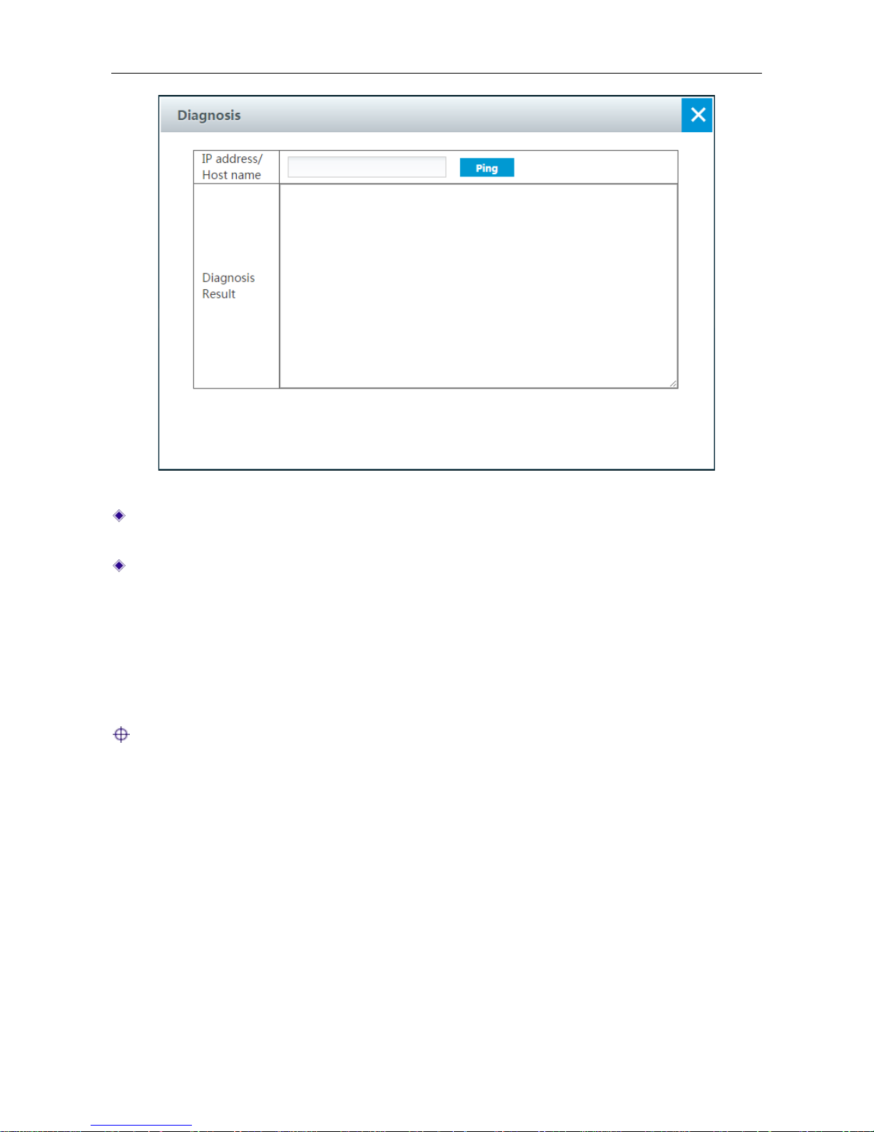
UTT Technologies Application
http://www.uttglobal.com Page 60
Figure 4-37 Diagnosis
IP address/Host name: Enter the device’s IP address you want to detect and then click the
Ping button.
Diagnosis Result: Displays the diagnosis result.
4.24 Flexible Bandwidth
On the Application > Flexible Bandwidth page, you can enable flexible bandwidth. When the
network is busy, the Device will assign traffic to each LAN users properly according to the current
numbers of LAN users, which ensure each LAN users running smoothly.
Notes: It is not suggested to enable Band width Control and Flexible Ban dwidth at the same
time.
Page 66
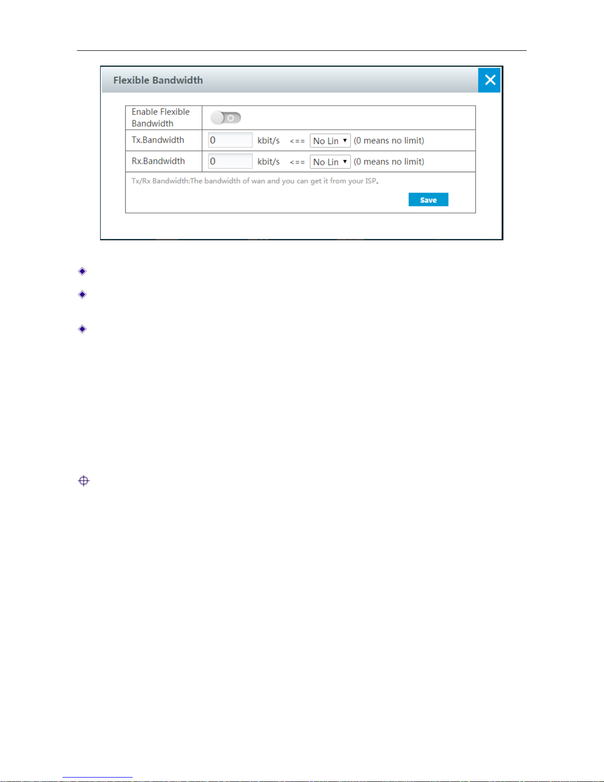
UTT Technologies Application
http://www.uttglobal.com Page 61
Figure 4-38 Game Boost
Enable Flexible Bandwidth: Click to enable flexible bandwidth.
Tx. Bandwidth: Specify the upload speed of Internet connection. The value 0 means unlimited
rate.
Rx. Bandwidth: Specify the download speed of Internet connection. The value 0 means unlimited
rate.
4.25 Easy Surfing
On the Application > Easy Surfing page, you can enable easy surfing. Once Easy Surfing is
enabled, the LAN hosts basic TCP/IP parameters (including IP address, subnet mask, gateway IP
address, and DNS server IP address) could be set to any value. The Device will automatically
enable proxy ARP, enable DNS proxy, and disable IP spoofing defense and allow those
non-IP/MAC binding users to access the Device and Internet.
Note:
1) The users with the same IP address cannot access the Internet at the same time.
2) A LAN user's IP address cannot be the same with the Device's LAN/WAN interface IP address,
gateway IP address, and primary/secondary DNS server IP address; otherwise, the user
cannot access the Device and Internet.
Page 67
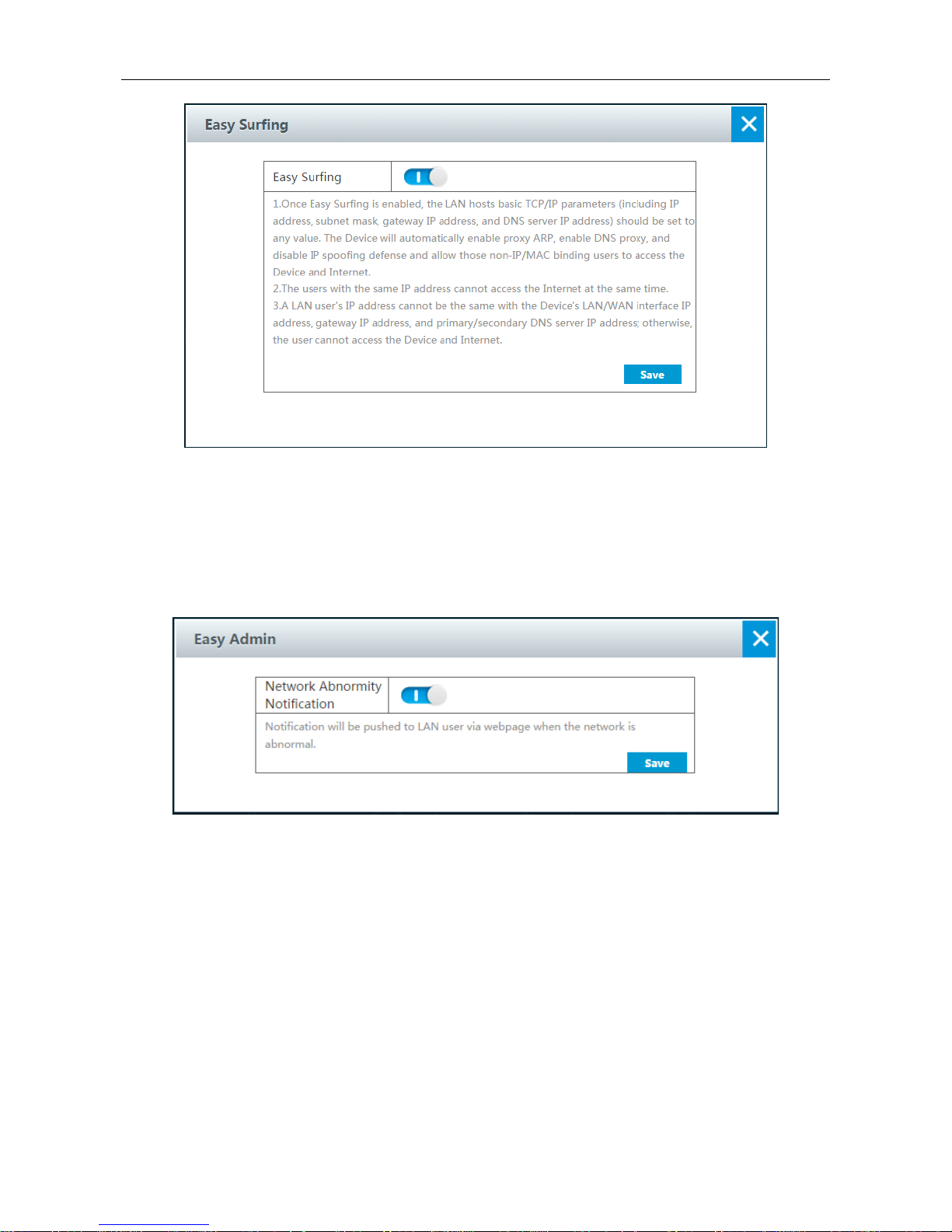
UTT Technologies Application
http://www.uttglobal.com Page 62
Figure 4-39 Easy Surfing
4.26 Easy Admin
On the Application > Eas y Ad m in page, you can enable easy Admin. When the Device can't
access to the Internet, it will automatically prompt a webpage to detect the problem.
Figure 4-40 Easy Admin
4.27 Cloud Storage
Cloud storage is a model of data storage where the digital data is stored in USB disk. The USB
disk is owned and managed by Administrator who is responsible for keeping the data available and
accessible. Users access to cloud storage for digital data.
Page 68
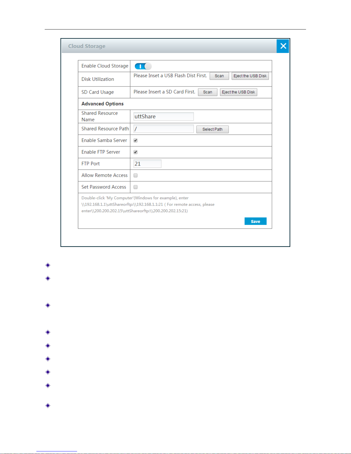
UTT Technologies Application
http://www.uttglobal.com Page 63
Figure 4-41 Cloud Storage
Enable Cloud Storage: Click the button to enable Cloud Storage.
Disk Utilization: Click the Scan button to scan available USB disk. Before clicking the scan
button, please insert the USB disk into the USB port. After clicking the scan button, it will show
the utilization of USB disk.
SD Card Usage: Click the Scan button to scan available TF card. Before clicking the scan
button, please insert the TF card into the TF port. After clicking the scan button, it will show the
utilization of TF card.
Shared Resource Name: Specify the name of folder you want to share.
Shared Resource Path: Click the Select Path button to select the resource path.
Enable Samba Server: Select to enable Samba Server.
Enable FTP Server: Select to enable FTP Server.
FTP Port: Specify the FTP server port. The default value is 21. The range of value is 1 to
65535.
Allow Remote Access: Select to enable remote access from WAN port.
Page 69

UTT Technologies Application
http://www.uttglobal.com Page 64
Set Password Access: Select to set password.
User Name: Specify the name which users use to access cloud storage.
Password: Specify the password which users use to access cloud storage.
Confirm Password: Enter the password again.
Note:
There are two ways to access cloud storage:
For local users:
1) Double-click 'My Computer', enter
\\192.168.1.1\uttShare (192.168.1.1 is the IP address of LAN
port.) in the address bar to open the shared resources folder.
2) Double-click 'My Computer', enter ftp:\\192.168.1.1:21 (192.168.1.1 is the IP address of LAN
port.) in the address bar to open the shared resources folder.
For remote users:
1) Double-click 'My Computer', enter\\200.200.202.15\uttShare (200.200.202.15 is the IP address
of WAN port.) in the address bar to open the shared resources folder.
2) Double-click 'My Computer', enter ftp:\\200.200.202.15:21 (200.200.202.15 is the IP address of
WAN port.) in the address bar to open the shared resources folder.
4.28 IP/MAC Binding
The Device provides IP/MAC binding feature to implement user identification. Using the IP/MAC
address pair as a unique user identity, you can protect the Device and your network against IP
spoofing attacks. IP spoofing attack refers to the situation when an attacker host attempts to use
another trusted host’s IP address to connect to or pass through the Device. The attacker can easily
change the host’s IP address to any trusted address, but difficult to change its MAC address as it is
burned to the Ethernet card at factory.
The IP/MAC binding feature allows you to add the IP and MAC address pairs of trusted LAN hosts
in the IP/MAC Binding List. Note that in the IP/MAC Binding List, you can allow or block Internet
access for each IP/MAC binding host. After you have added a LAN host’s IP and MAC address pair
into the IP/MAC Binding List, if Allow check box is selected (check mark
√ appears), it will allow
the host to access the Device and Internet, else block the user.
4.28.1 The Operation Principle of IP/MAC Binding
For the sake of convenience, we firstly introduce several related terms including legal user, illegal
user and undefined user.
Legal User: A legal user’s IP and MAC address pair matches an IP/MAC binding, of which the
Allow check box is selected.
Page 70

UTT Technologies Application
http://www.uttglobal.com Page 65
Illegal User: A illegal user’s IP and MAC address pair matches an IP/MAC binding, of which the
Allow check box is unselected; or there’s only one of the IP address and MAC address that
matches the IP/MAC binding.
Undefined User: An undefined user’s IP address and MAC address are both different from any
IP/MAC binding. The undefined users are the rest of users except legal and illegal users.
It allows the legal users to access the Device and access the Internet through the Device, and
denies the illegal users. And the parameter of Allow Undefined LAN PCs determines whether it
allows the undefined users to access the Device and access the Internet th rough the Dev ice, that is,
it will allow them if the Allow Undefined LAN PCs check box is selected, else block them.
IP/MAC binding feature can act on the packets initiated from the LAN hosts to the Device or outside
hosts. When receiving a packet initiated from LAN, the Device will firstly determine the sender’s
identity by comparing the packet with the bindings in the IP/MAC Binding List, and then process
the packet according to the sender’s identity, detailed procedure as follows:
1) If the sender is a legal user, the packet will be allowed to pass.
2) If the sender is an illegal user, the packet will be dropped immediately to prevent IP spoofing.
3) If the sender is an undefined user, there are two cases:
(1) If the A llow Undefined LAN PCs check box is selected, the packet w ill be allowed to pass .
(2) Else, the packet will be dropped immediately.
For example, if the IP/MAC address pair IP 192.168.16.65 and 00:15:c5:67:41:0f is added to the
IP/MAC Binding List, and its Allow check box is selected, see the following figure.
Page 71
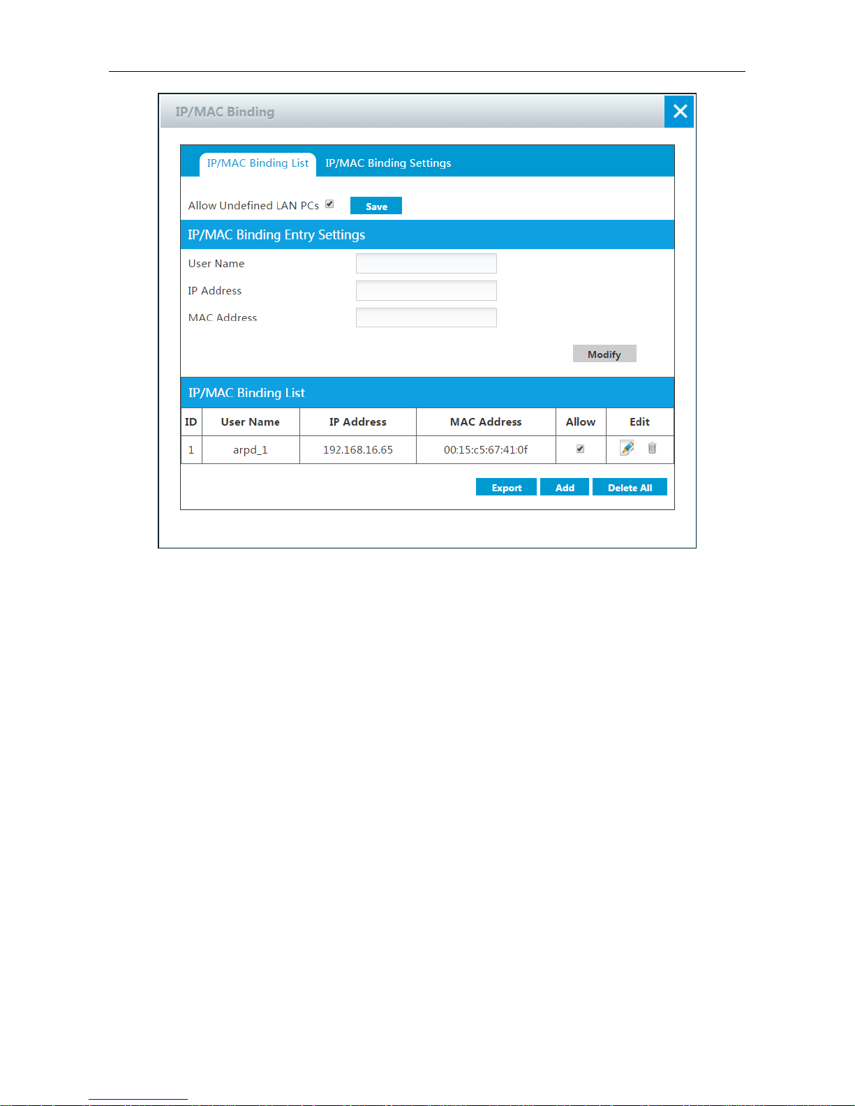
UTT Technologies Application
http://www.uttglobal.com Page 66
Figure 4-42 IP/MAC Binding - Example One
Then, when receiving a packet initiated from LAN, the Device will process it according to the
following cases:
1) A packet with IP address 192.168.16.65 and MAC address 00:15:c5:67:41:0f is allowed to
pass.
2) A packet with IP address 192.168.16.65 but with a different MAC address is dropped
immediately to prevent IP spoofing.
3) A packet with a different IP address but with MAC address 00:15:c5:67:41:0f is dropped
immediately to prevent IP spoofing.
4) A packet’s IP address and MAC address both are not defined in the IP/MAC Binding List:
(1) If the Allow Undefined LAN PCs check box is selected, the packet is allowed to pass.
(2) Else, the packet is dropped.
If you want to block the user who matches the IP/MAC binding from accessing the Device and
Internet, you need unselect Allow check box, see the following figure. Then a packet with IP
address 192.168.16.65 and MAC address 00:15:c5:67:41:0f will be dropped.
Page 72
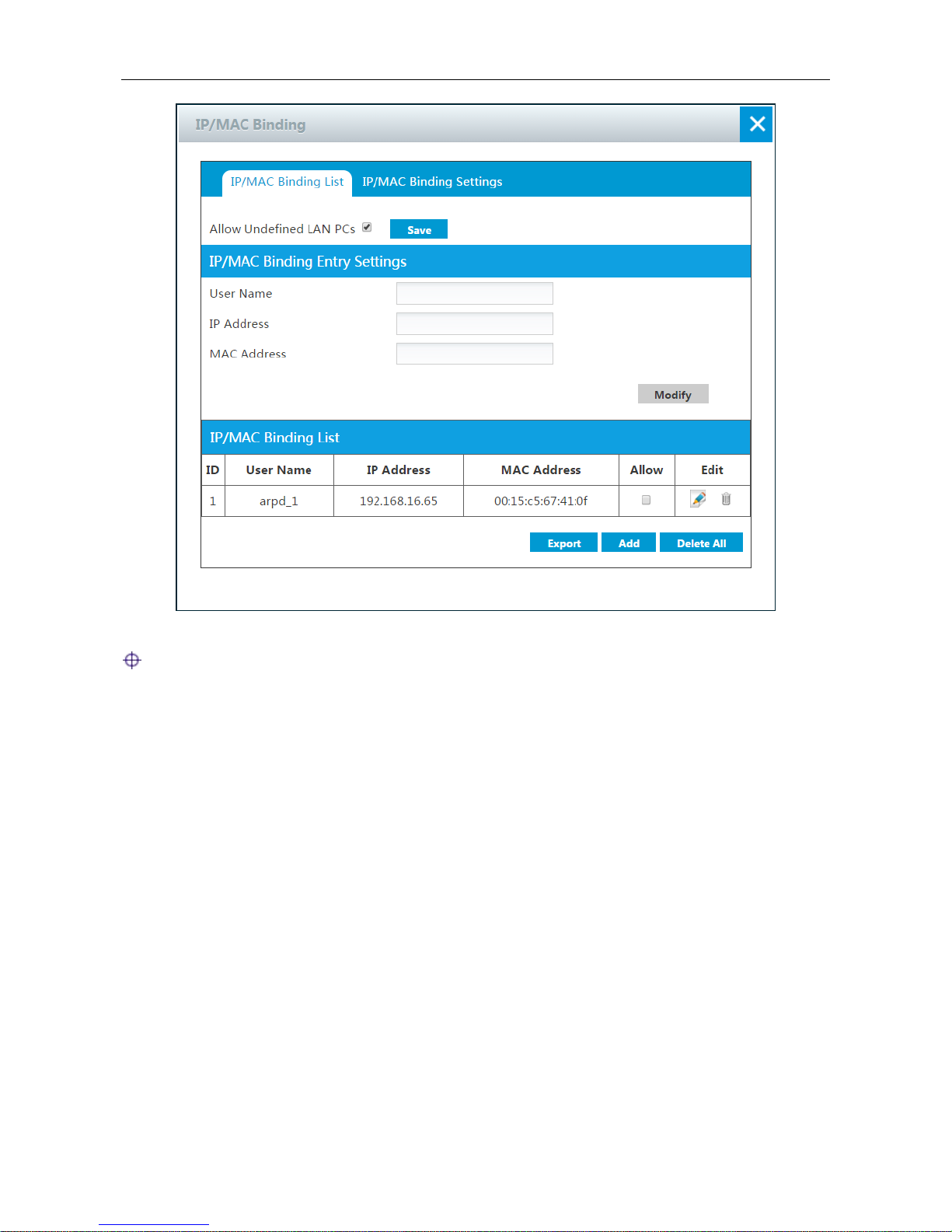
UTT Technologies Application
http://www.uttglobal.com Page 67
Figure 4-43 IP/MAC Binding - Example Two
Note:
1) If you have added the IP and MAC address pair of a trusted LAN host in the IP/MAC Binding
List, and later changed this host’s IP address or MAC address, you must also update the
corresponding binding in the IP/MAC Binding List; otherwise the host cannot access the
Device and Internet. If the Allow Undefined LAN PCs check box is unselected, you must also
add the IP and MAC address pair of any new host that you add to your network, and make sure
that its Allow check box is selected; otherwise this new host cannot access the Device and
Internet.
2) IP/MAC binding feature can only act on the packets initiated from the LAN hosts to the Device
or outside hosts, but cannot act on the packets within the LAN. If you change a LAN host’s IP
address or MAC address, this LAN host will be unable to access the Device and access the
Internet through the Device, but it still can communicate with the other LAN hosts, such as, it
can browse Network Neighborhood, use windows file and printer sharing services within the
LAN, and so on.
3) If you want to unselect the Allow Undefined LAN PCs check box to block the undefined LAN
hosts from accessing or passing through the Device, you should make sure that you have
added the IP/MAC address pair of the host that you use to administer the Device into the
IP/MAC Binding List.
Page 73
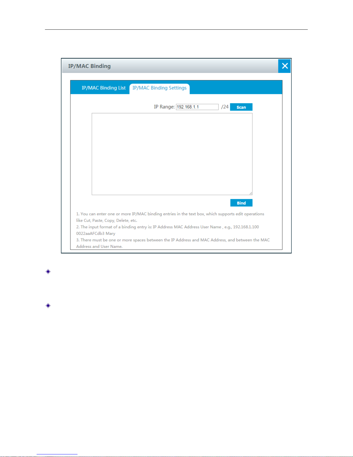
UTT Technologies Application
http://www.uttglobal.com Page 68
4.28.2 IP/MAC Binding Settings
Figure 4-44 IP/MAC Binding Settings
Scan: If you click the Scan button, the Device will immediately scan the LAN to detect active
hosts connected to the Device, learn and display dy namic ARP in formation (that is, IP and MAC
address pairs). Note that if you have added a LAN host’s IP and MAC address pair in the
IP/MAC Binding List, this IP/MAC address pair will not be displayed here.
Bind: Click it to bind all the valid IP and MAC address pairs in the list box.
Also you can manually create one or more IP/MAC bindings, the operation is as follows: Add
one or more IP/MAC address pair entries in the list box, and then click the Bind button. The
input contents are: IP Address, MAC Address, one address pair entry per line; and the input
format of an address pair entry is: IP Address<Space>MAC Address <Enter>.
4.29 VPN
PPTP and L2TP are the two most popular VPN tunneling protocols. Tunneling protocols are the
heart of all VPN implementations. VPN tunneling involves establishing and maintaining a logical
network connection, on which the encapsulated packets are transmitted securely.
Page 74

UTT Technologies Application
http://www.uttglobal.com Page 69
For PPTP and L2TP, tunneling protocols operate at the data link layer (Layer 2) of the OSI model.
They use frames as their unit of exchange, and encapsulate the original packets inside PPP frames
before sending them through a VPN tunnel over the Internet.
PPTP and L2TP are based on client/server model. The client initiates a connection to the server,
while the server accepts the incoming connection from the client. PPTP and L2TP is often used to
implement remote access VPNs over an IP network (such as a broadband network), to extend the
reach of your Intranet. The Device can only act as the client.
4.29.1 Typical Application
As shown in the following figure, to securely connect an enterprise’s head office, the Device acts as
the client. The VPN gateway deployed at the head office acts as the server. O nce the client
receives a packet destined for the remote LAN, it will initiate the tunnel setup request to the server;
the server will authenticate the connection.
If the user authentication succeeds (such as username and password match), the serv er will accept
the incoming connection; at this point, a tunnel between the client and the server is established. And
the server will forward the original packets to the intended destinations.
If the user authentication fails, the server will reject the incoming tunnel setup request. Thus the
tunnel cannot be established due to user authentication failure, and any packets destined for the
remote LAN will be discarded by the client.
Figure 4-45 Typical Application
Page 75
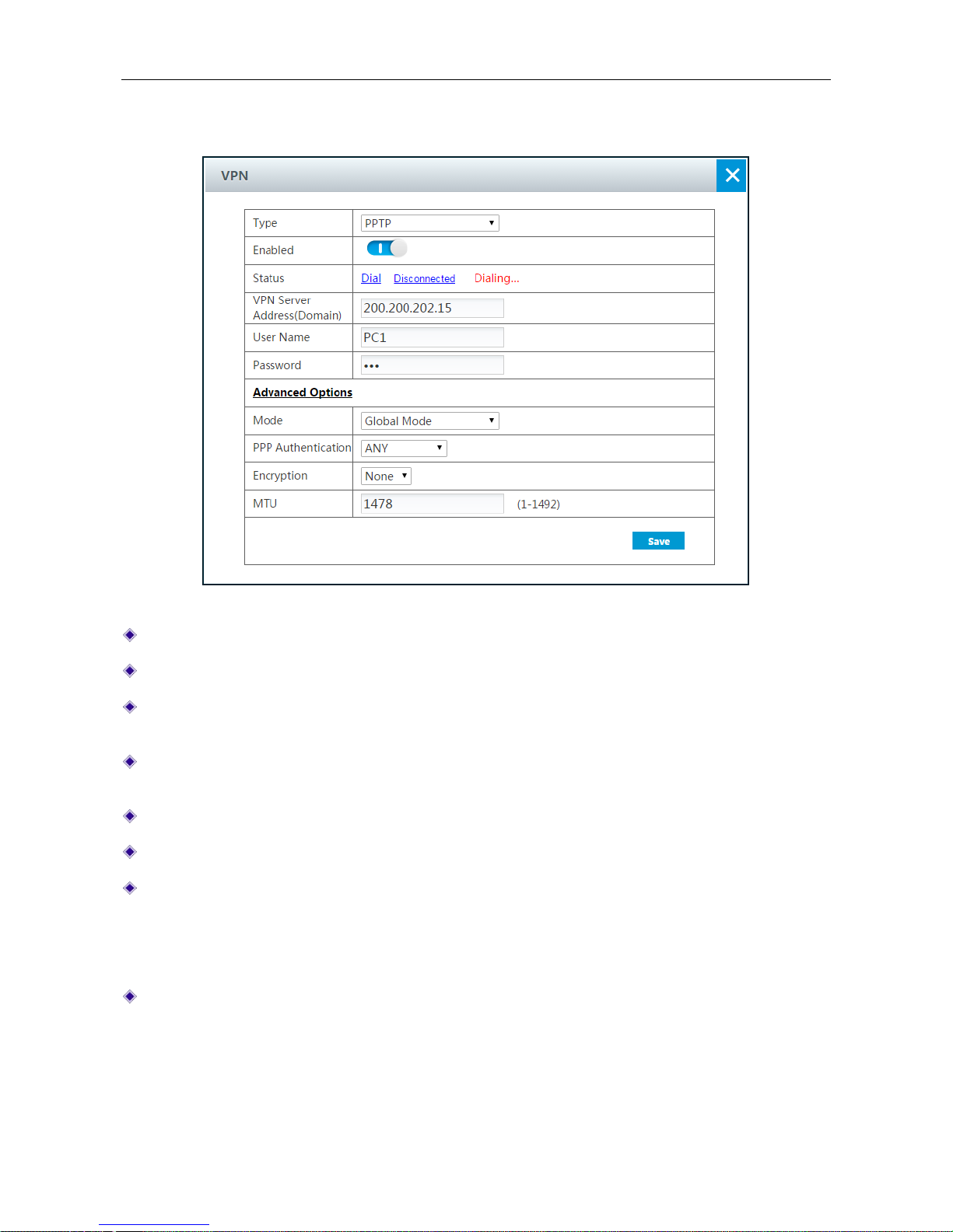
UTT Technologies Application
http://www.uttglobal.com Page 70
4.29.2 VPN Settings
Figure 4-46 PPTP Client Settings
Type: Select the VPN tunneling protocols.
Enabled: Click to enable the connection.
Status: There are two buttons: Dial and Disconnected. Click Dial to dialing the connection.
Click Disconnected to disconnect the connection.
VPN Server Address (Domain): Specify the IP address or the domain name of the VPN
server.
User Name: Enter the user name of the client which has been set on the VPN server.
Password: Enter the password.
Mode: There are two VPN modes.
Global Mode: All the packets will pass through the VPN tunnel.
Specific Subnet Mode: The packets of specified subnet will pass through the VPN tunnel.
PPP Authentication: Select the PPP authentication mode of the tunnel. It should be the same
value as that on the server. The available options are PAP, CHAP, MS-CHAPV2 and ANY.
PAP: Password Authentication Protocol.
CHAP: Challenge Handshake Authentication Protocol.
Page 76
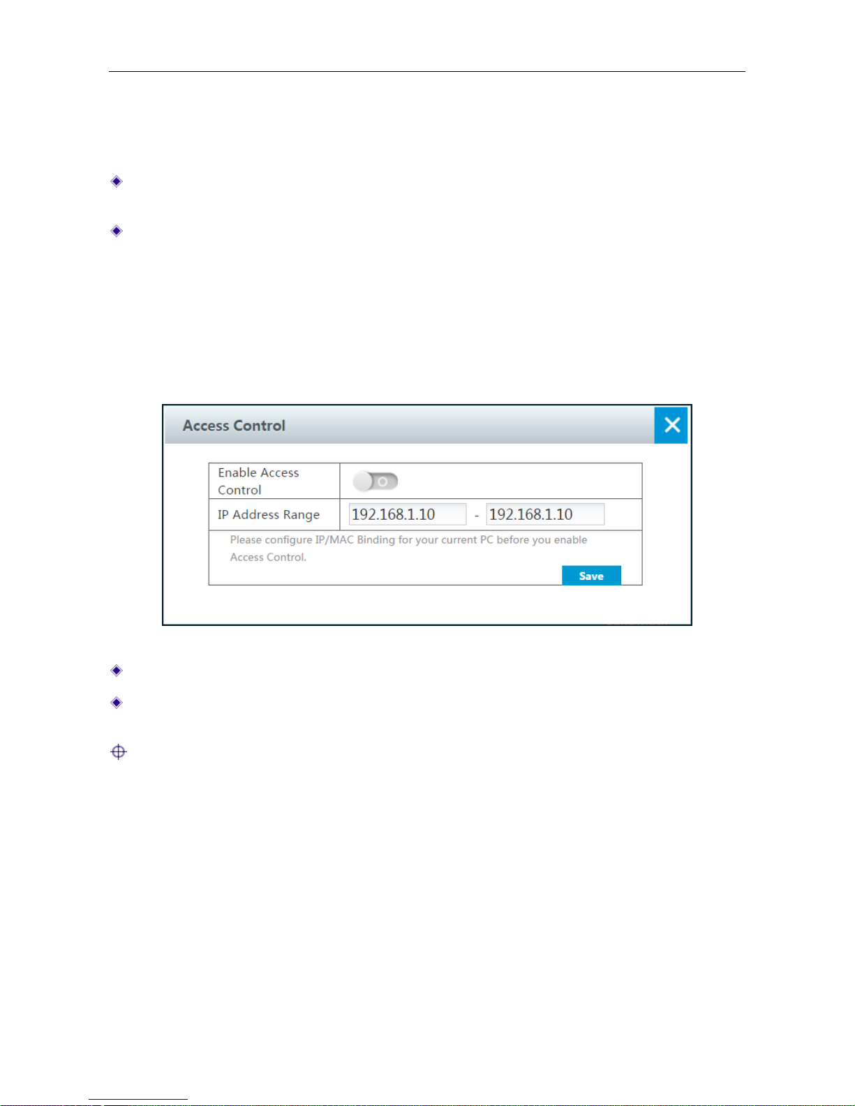
UTT Technologies Application
http://www.uttglobal.com Page 71
MS-CHAPV2: the Microsoft version of the Challenge-Handshake Authentication Protocol.
ANY: If selected, VPN gateway will automatically negotiate it with the remote VPN
appliance.
Encryption: Select the way of data encryption mode. Note when you choose MS-CHAPV2 as
PPP aunthentication mode, you must select MPPE as data encryption mode.
MTU: Specify the largest packet size permitted for network receive. During dialing, The VPN
gateway will automatically negotiate it with the remote VPN appliance when dialing. Unless
special application, please leave the default value of 1478 bytes.
4.30 Access Control
On the Application > Access Control page, you can specify the IP addresses of LAN us ers who
can access to the Device to do the settings.
Figure 4-47 Access Control
Enable Access Control: Click to enable Access Control.
IP Address Range: Specify the IP address range of LAN users who can access to the Device
to do the settings.
Notes: If you have enabled DHCP Server, the LAN users will obtain IP address automatically
on and on, so in case of users can’t access to the Device, please configure IP/MAC Binding for
your current device before you enable Access Control.
Page 77

UTT Technologies Appendix A FAQ
http://www.uttglobal.com Page 72
Appendix A FAQ
Q: How to configure your TCP/IP?
A: There are two methods of configuring TCP/IP properties: one is to manually configure TCP/IP
properties; the other is to automatically configure TCP/IP properties with DHCP. The following
describes the configuration procedure of these two methods respectively.
Method One: Manually Configuring TCP/IP
To configure the TCP/IP protocol manually, do the following:
1) On the Windows taskbar, click Start > Control Panel > Network and Connection > Local
Area Connection, right click Local Area Connection, and choose Properties.
2) In the Properties dialogue, double click Internet Protocol Version 4 (TCP/IPv4).
3) In the Internet Protocol Version 4 (TCP/IPv4) dialogue, select the Use the following IP
address radio button, Enter 192.168.1.x (x is between 2 and 254, including 2 and 254) in the IP
Address box, ent er 255.255.255.0 in the Subnet Mask box, and Enter t he IP address of the
Device’s LAN interface (default value is 192.168.1.1) in the Default gateway textbox.
4) Select the Use the following DNS server addresses radio button, Enter the IP address of
DNS server into the Preferred DNS server textbox.
Page 78
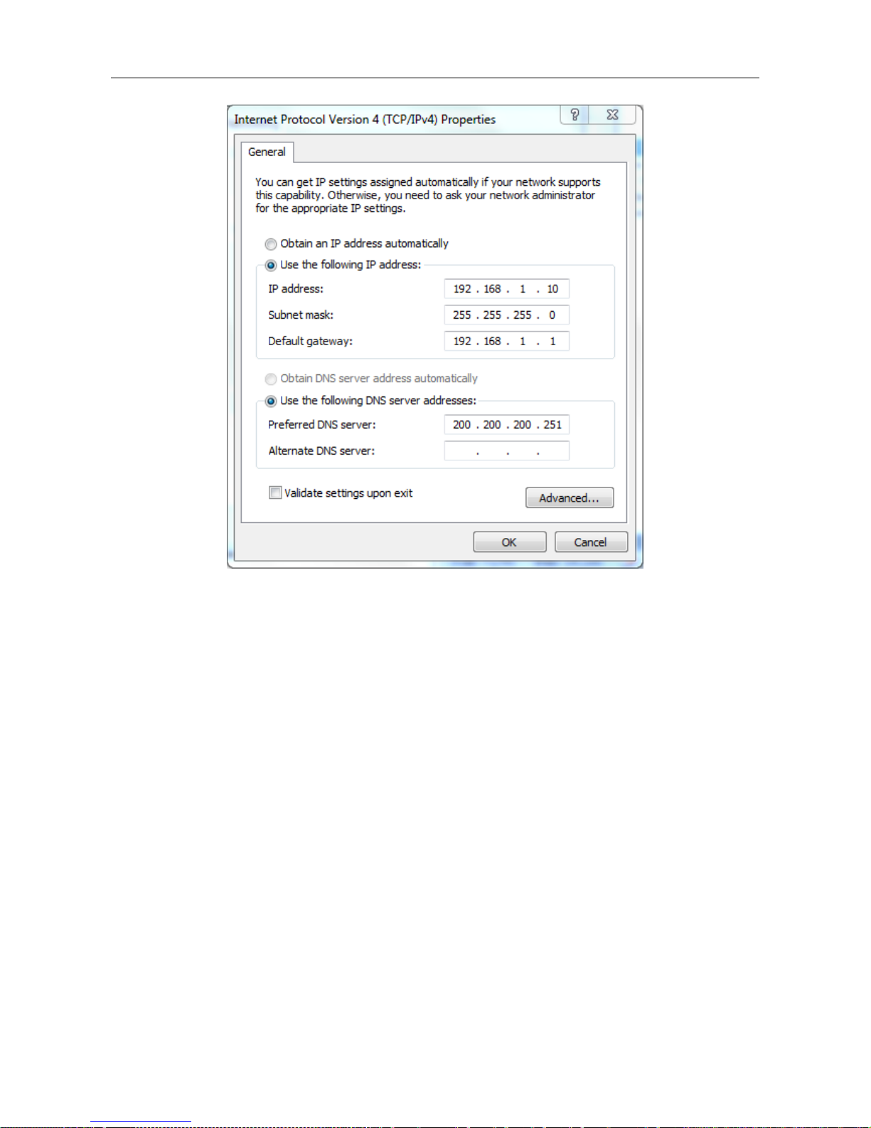
UTT Technologies Appendix A FAQ
http://www.uttglobal.com Page 73
Figure Appendix- 1 Manually configuring TCP/IP
5) Click OK in the Internet Protocol Version 4 (TCP/IPv4) dialogue, this will return you to the
Local Area Connection Properties dialogue. Click OK again. Till now you have finished
configuring the TCP/IP properties.
Method Two: Automatically Configuring TCP/IP with DHCP
To ensure that the host can obtain an IP address and other TCP/IP parameters automatically from
the Device, you should enable the Device’s DHCP server function in Application > DHCP Server
page.
1) On the Windows taskbar, click Start > Control Panel > Network and Connection > Local
Area Connection, right click Local Area Connection, and choose Properties.
2) In the Properties dialogue, double click Internet Protocol Version 4 (TCP/IPv4).
3) In the Internet Protocol Version 4 (TCP/IPv4) dialogue, select the Obtain an IP address
automatically radio button, and select the Obtain DNS server address automatically radio
button.
Page 79
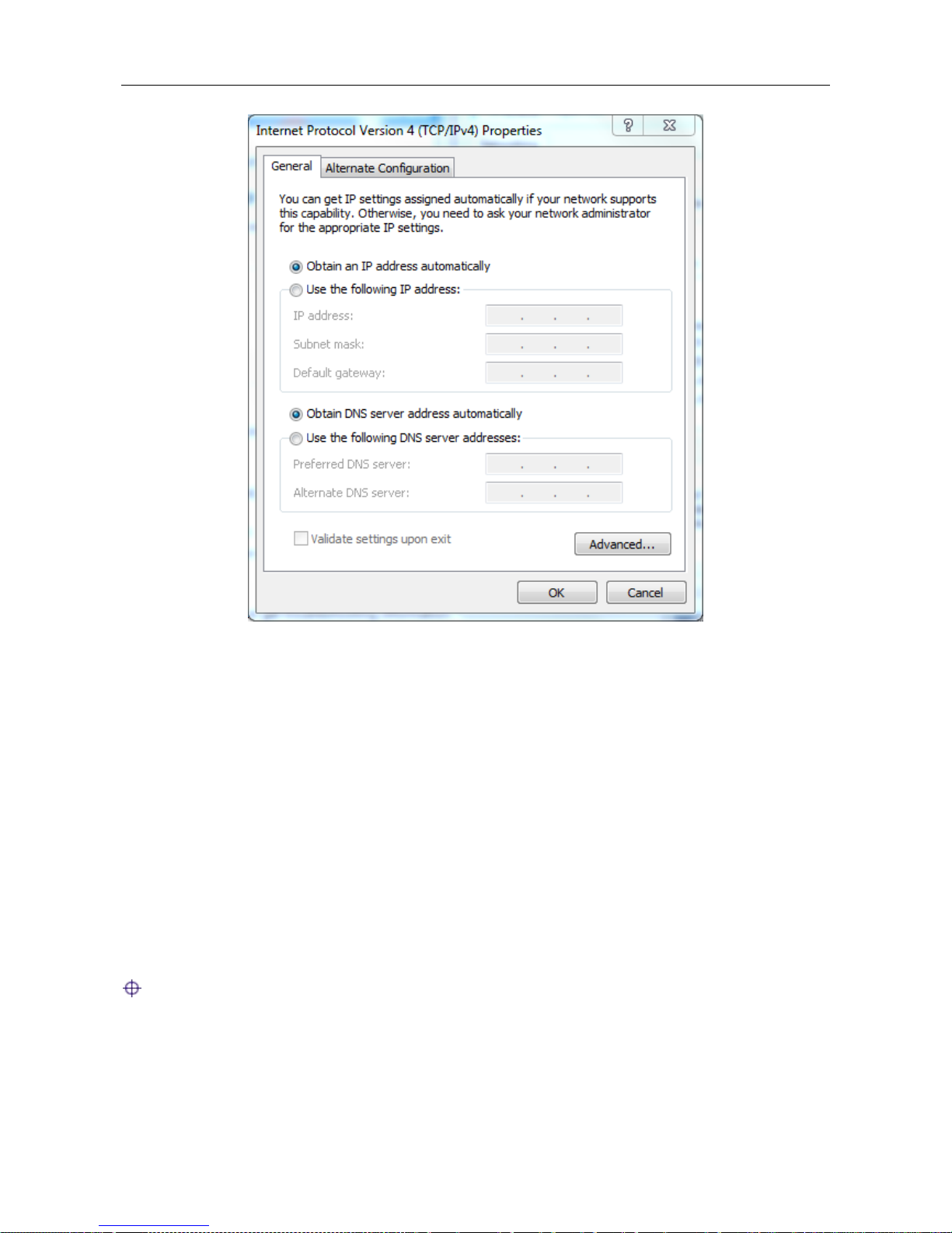
UTT Technologies Appendix A FAQ
http://www.uttglobal.com Page 74
Figure Appendix- 2 Automatically Configuring TCP/IP with DHCP
4) Click OK in the Internet Protocol Version 4 (TCP/IPv4) dialogue, this will return you to the
Local Area Connection Properties dialogue. Click OK again. Till now you have finished
configuring the TCP/IP properties.
Q: How to reset the Device to factory default settings?
A: When you remember the administrator password, you can go to th e Application >
Configuration page, and then click OK button to reset the Device to factory default settings.
If you forget the administrator password, you can use a pin to press and hold the Reset button for
more than 5 seconds when the device is on, and then release the button. After that, the Device will
restart with factory default settings.
Note: The reset operation will clear all the custom settings on the Device, so do it with caution.
Page 80

UTT Technologies Appendix B Common IP Protocols
http://www.uttglobal.com Page 75
Appendix B Common IP Protocols
Protocol Name Protocol Number Full Name
IP 0 Internet Protocol
ICMP 1 Internet Protocol Message Protocol
IGMP 2 Internet Group Management
GGP 3 Gateway-Gateway Protocol
IPINIP 4 IP in IP Tunnel Driver
TCP 6 Transmission Control Protocol
EGP 8 Exterior Gateway Protocol
IGP 9 Interior Gateway Protocol
PUP 12 PARC Universal Packet Protocol
UDP 17 User Datagram Protocol
HMP 20 Host Monitoring Protocol
XNS-IDP 22 Xerox NS IDP
RDP 27 Reliable Datagram Protocol
GRE 47 General Routing Encapsulation
ESP 50 Encap Securit y Payload
AH 51 Aut hent icat ion Header
RVD 66 MIT Remote Virtual Disk
EIGRP 88 Enhanced Interior Gateway Routing Protocol
OSPF 89 Open Shortest Path First
Page 81

UTT Technologies Appendix C Common Service Ports
http://www.uttglobal.com Page 76
Appendix C Common Service Ports
Service Name Port Protocol Description
echo 7 tcp
echo 7 udp
discard 9 tcp
discard 9 udp
systat 11 tcp Active users
systat 11 udp Active users
daytime 13 tcp
daytime 13 udp
qotd 17 tcp Quote of the day
qotd 17 udp Quote of the day
chargen 19 tcp Character generator
chargen 19 udp Character generator
ftp-data 20 tcp FTP, data
ftp 21 tcp FTP. control
telnet 23 tcp
smtp 25 tcp Simple Mail Transfer Protocol
time 37 tcp timserver
time 37 udp timserver
rlp 39 udp Resource Location Protocol
nameserver 42 tcp Host Name Server
nameserver 42 udp Host Name Server
nicname 43 tcp whois
domain 53 tcp Domain Name Server
domain 53 udp Domain Name Server
bootps 67 udp Bootstrap Protocol Server
bootpc 68 udp Bootstrap Protocol Client
Page 82

UTT Technologies Appendix C Common Service Ports
http://www.uttglobal.com Page 77
tftp 69 udp Trivial File Transfer
gopher 70 tcp
finger 79 tcp
http 80 tcp World Wide Web
kerberos 88 tcp Kerberos
kerberos 88 udp Kerberos
hostname 101 tcp NIC Host Name Server
iso-tsap 102 tcp ISO-TSAP Class 0
rtelnet 107 tcp Remote Telnet Service
pop2 109 tcp Post Office Protocol - Version 2
pop3 110 tcp Post Office Protocol - Version 3
sunrpc 111 tcp SUN Remote Procedure Call
sunrpc 111 udp SUN Remote Procedure Call
auth 113 tcp Identification Protocol
uucp-path 117 tcp
nntp 119 tcp Network News Transfer Protocol
ntp 123 udp Network Time Protocol
epmap 135 tcp DCE endpoint resolution
epmap 135 udp DCE endpoint resolution
netbios-ns 137 tcp NETBIOS Name Service
netbios-ns 137 udp NETBIOS Name Service
netbios-dgm 138 udp NETBIOS Dat agram Service
netbios-ssn 139 tcp NETBIOS Session Service
imap 143 tcp Internet Message Access Protocol
pcmail-srv 158 tcp PCMail Server
snmp 161 udp
snmptrap 162 udp SNMP trap
print-srv 170 tcp Network PostScript
bgp 179 tcp Border Gateway Protocol
irc 194 tcp Internet Relay Chat Protocol
Page 83

UTT Technologies Appendix C Common Service Ports
http://www.uttglobal.com Page 78
ipx 213 udp I PX over I P
ldap 389 tcp Lightweight Directory Access Protocol
https 443 tcp MCom
https 443 udp MCom
microsoft-ds 445 tcp
microsoft-ds 445 udp
kpasswd 464 tcp Kerberos (v5)
kpasswd 464 udp Kerberos (v5)
isakmp 500 udp Int ernet Key Exchange
exec 512 tcp Remote Process Execution
biff 512 udp
login 513 tcp Remote Login
who 513 udp
cmd 514 tcp
syslog 514 udp
printer 515 tcp
talk 517 udp
ntalk 518 udp
efs 520 tcp Extended File Name Server
router 520 udp route routed
timed 525 udp
tempo 526 tcp
courier 530 tcp
conference 531 tcp
netnews 532 tcp
netwall 533 udp For emergency broadcasts
uucp 540 tcp
klogin 543 tcp Kerber os login
kshell 544 tcp Ker ber os remote shell
new-rwho 550 udp
Page 84

UTT Technologies Appendix C Common Service Ports
http://www.uttglobal.com Page 79
remotefs 556 tcp
rmonitor 560 udp
monitor 561 udp
ldaps 636 tcp LDAP over TLS/SSL
doom 666 tcp Doom Id Software
doom 666 udp Doom Id Software
kerberos-adm 749 tcp Kerberos administration
kerberos-adm 749 udp Ker ber os administration
kerberos-iv 750 udp Kerberos version IV
kpop 1109 tcp Kerberos POP
phone 1167 udp Conf erence calling
ms-sql-s 1433 tcp Microsoft-SQL-Server
ms-sql-s 1433 udp Microsoft-SQL-Server
ms-sql-m 1434 tcp Microsoft-SQL-Monitor
ms-sql-m 1434 udp Microsoft-SQL-Monitor
wins 1512 tcp Microsoft Windows Internet Name Service
wins 1512 udp Microsoft Windows Internet Name Service
ingreslock 1524 tcp
l2tp 1701 udp Layer Two Tunneling Protocol
pptp 1723 tcp Point-to-point tunnelling protocol
radius 1812 udp RADIUS authentication protocol
radacct 1813 udp RADIUS accounting protocol
nfsd 2049 udp NFS server
knetd 2053 tcp Kerberos de-multiplexor
man 9535 tcp Remote Man Server
 Loading...