

Page 1

HiPER 811
Quick Guide
2009-3-17
Version: 1.2
Page 2

Copyright Notice
Copyright © 2000-2009, Shanghai UTT Technologies Co., Ltd.
All rights reserved.
The information of this publication is protected by copyright. No part of this publication
may be reproduced, transmitted, transcribed, stored in a retrieval system, or translated
into any language without written permission from the copyright holders. The scope of
delivery and other details are subject to change without prior notice.
Trademark
UTT® is a registered trademark of Shanghai UTT Technologies Co., Ltd.
HiPER® is a registered trademark of Shanghai UTT Technologies Co., Ltd.
Other trademarks and registered trademarks of products mentioned in this publication
may be the properties of their respective owners and are only used for identification
purposes.
Page 3

Warning
This equipment has been tested and found to comply with the limits for a Class B digital
device, pursuant to part 15 of the FCC Rules. These limits are designed to provide
reasonable protection against harmful interference in a residential installation. This
equipment generates, uses and can radiate radio frequency energy and, if not installed
and used in accordance with the instructions, may cause harmful interference to radio
communications. However, there is no guarantee that interference will not occur in a
particular installation. If this equipment does cause harmful interference to radio or
television reception, which can be determined by turning the equipment off and on, the
user is encouraged to try to correct the interference by one or more of the following
measures:
Reorient or relocate the receiving antenna.
Increase the separation between the equipment and receiver.
Connect the equipment into an outlet on a circuit different from that to which the
receiver is connected.
Consult the dealer or an experienced radio/TV technician for help.
Caution: Any changes or modifications to this device not explicitly approved by
manufacturer could void your authority to operate this equipment.
Page 4

Page I
Table of Contents
About This Guide ................................................................................................................. 1
0.1 Conventions ............................................................................................ 1
0.1.1 Conventions for page path ..................................................................... 1
0.1.2 Common Button ...................................................................................... 1
0.1.3 List .......................................................................................................... 2
0.1.3.1 Editable List ............................................................................................ 2
0.1.3.2 Read-only List ......................................................................................... 3
0.1.3.3 Sorting Function ...................................................................................... 4
0.2 Factory Default Settings ......................................................................... 4
Chapter 1 Product Overview ................................................................................... 5
1.1 Key Features .......................................................................................... 5
1.2 Specifications .......................................................................................... 7
Chapter 2 Physical Installation ................................................................................ 8
2.1 Front Panel ............................................................................................. 8
2.1.1 LEDs ....................................................................................................... 8
2.1.2 Ports ........................................................................................................ 9
2.1.3 Reset Button ........................................................................................... 9
2.2 Connecting the Device ......................................................................... 11
Chapter 3 Quick Setup Guide ................................................................................ 12
3.1 Configure PC ........................................................................................ 12
3.2 Login the Device ................................................................................... 14
3.3 Internet Connection .............................................................................. 17
3.3.1 Internet Connection Setup .................................................................... 17
3.3.1.1 PPPoE Connection ............................................................................... 19
3.3.1.2 Static IP Connection ............................................................................. 22
3.3.1.3 DHCP Connection ................................................................................ 23
3.3.2 Internet Connection List ........................................................................ 24
3.3.3 How to Dial and Hang up a PPPoE connection ................................... 26
3.3.4 How to Renew and Release a DHCP Connection ................................. 27
3.3.5 How to Edit the Connection .................................................................. 28
Page 5

Page II
3.3.6 How to Delete the Connection .............................................................. 28
3.4 Network Security ................................................................................... 29
3.4.1 Virus Defense ....................................................................................... 29
3.4.2 Rate Limit .............................................................................................. 30
3.5 ARP Spoofing Defense ......................................................................... 31
3.5.1 ARP Spoofing Defense Setup .............................................................. 31
3.5.2 Dynamic ARP Table .............................................................................. 31
3.5.3 How to Defense Against ARP Spoofing Attack ..................................... 32
3.6 Port Forwarding .................................................................................... 33
3.6.1 Port Forwarding Setup .......................................................................... 33
3.6.2 Port Forwarding Rule List ..................................................................... 34
3.7 Change Administrator’s Password ....................................................... 35
3.8 Remote Management ........................................................................... 36
Appendix Contact Information ........................................................................................... 37
Page 6

Page 1
About This Guide
Note
For best use of our product, it is strongly recommended that you update Windows
Internet Explorer browser to 6.0 or above.
0.1 Conventions
0.1.1 Conventions for page path
Lever one menu > lever two menu(bold)means the menu path to open some
configuration page. E.g. System admin > Time means that in web interface, first click
level one menu system admin, then click level two menu Time to open clock
management page.
0.1.2 Common Button
Following common action buttons are used in this doc.
: Save and apply current settings.
: Cancel current settings and recover to the previous saved settings.
: Refresh the information on page.
: Acquire related help information.
Page 7
Page 2
: Delete the selected entry(s) with the corresponding settings.
0.1.3 List
In web page there are two kinds of lists: Editable list and read-only list.
0.1.3.1 Editable List
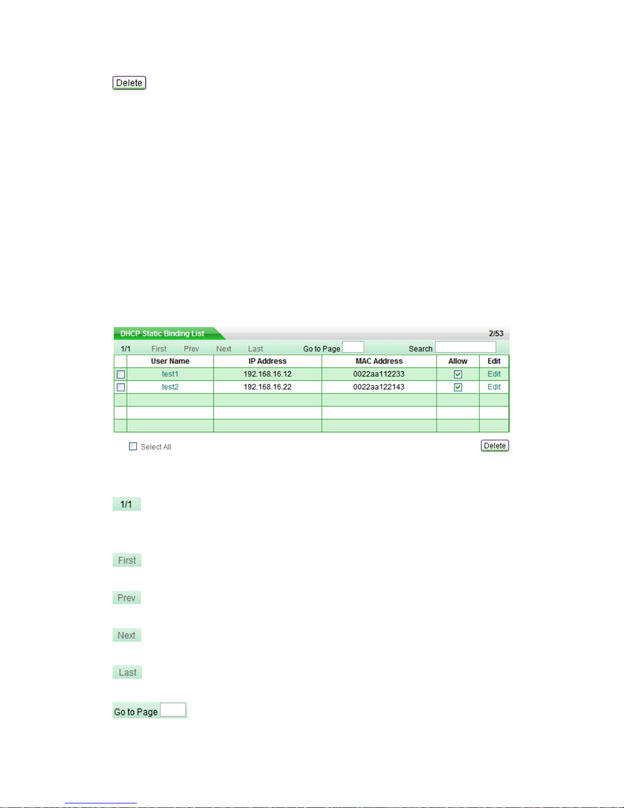
Editable list is used to display, edit and delete configuration item. Let us take DHCP
Static Binding List (see Table 0-1) as an example to explain the functions.
Table 0-1 DHCP Static Binding List
: Current page number/ total pages, the example means the current page is first
page, and total one page.
: Go to the first page.
: Go to the previous page.
: Go to the next page.
: Go to the last page.
: Enter page number in text field, then click Go to or type <Enter> to
Page 8
Page 3
jump to that page.
: Enter the search text in text field, then type <Enter> to display
all the matched entries, besides, you can search within results. After search, if you want
to display all the entries, you only need type <Enter> in empty text field.
Note: The match criterion is that search text exists in entry’s information.
: Created entry number / maximum number, the example means two DHCP static
binding entries have been set up and the maximum configurable entries number is 53.
: Click to open corresponding edit page.
: Select it to select all the entries in current page. Else, unselect all the
entries.
: First select some entry(s) (by selecting the leftmost check box), and then click
it to delete the selected entry(s).
0.1.3.2 Read-only List
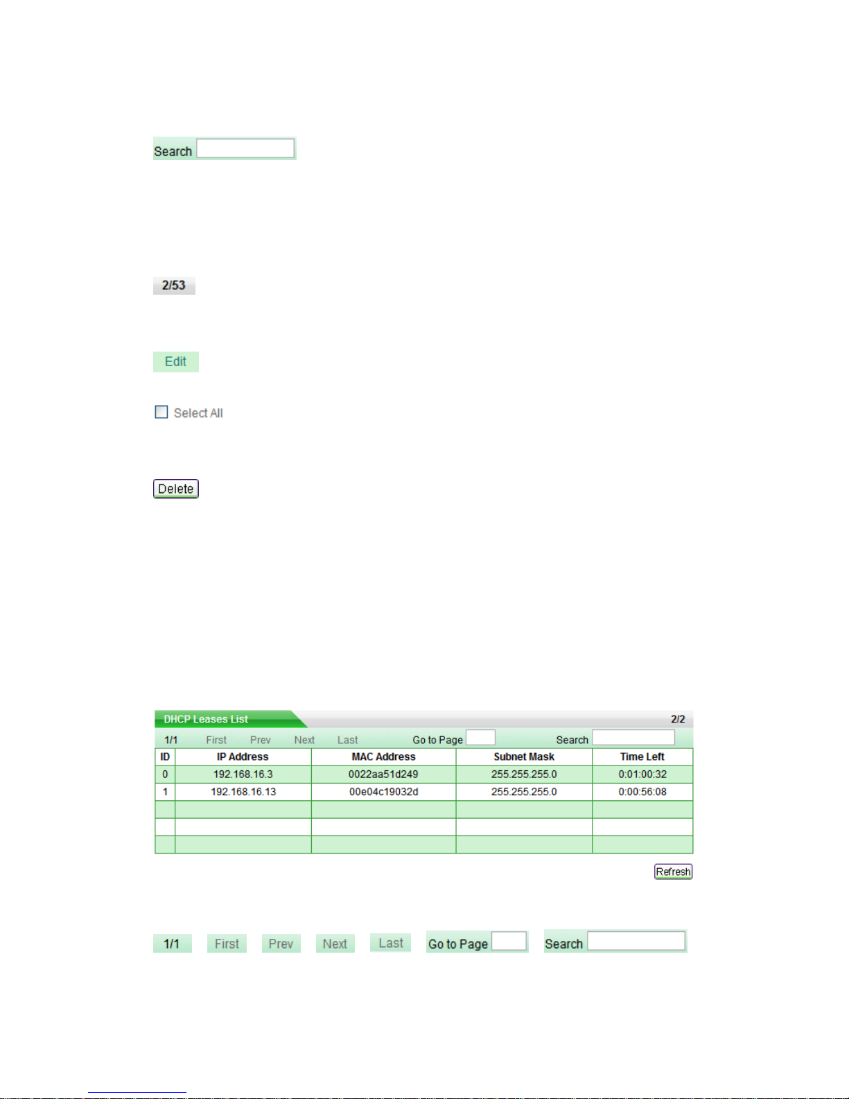
Read-only list is used to display the system status information that is not editable. Let us
take DHCP Leases List (see Table 0-2) as an example to explain the functions.
Table 0-2 DHCP Leases List
, , , , , ,
have the same meaning of the former.
Page 9

Page 4
: Current status entry number /maximum number,the example means there are
two status information entry in the list.
: Refresh the list to view current status of the list.
0.1.3.3 Sorting Function
Except Access Rule List in Advanced Setup > Access Rule page, all the lists in web
page support sorting function. Steps are as following:
Clicking the column title in list will make the list sorts the data by clicked column. The first
click makes it sorted descendingly. And the secondary click makes it sorted ascendingly.
The third one is descending again, and so forth. Each sorting will make the list display
the first page.
0.2 Factory Default Settings
1. The following table provides the factory default settings of Interfaces.
Interface
IP Address
Subnet Mask
LAN
192.168.16.1
255.255.255.0
WAN
192.168.17.1
255.255.255.0
Table 0-3 the Factory Default Settings of Interfaces
2. The default administrator’s user name is Default (case sensitive) with empty
password.
Page 10
Page 5
Chapter 1 Product Overview
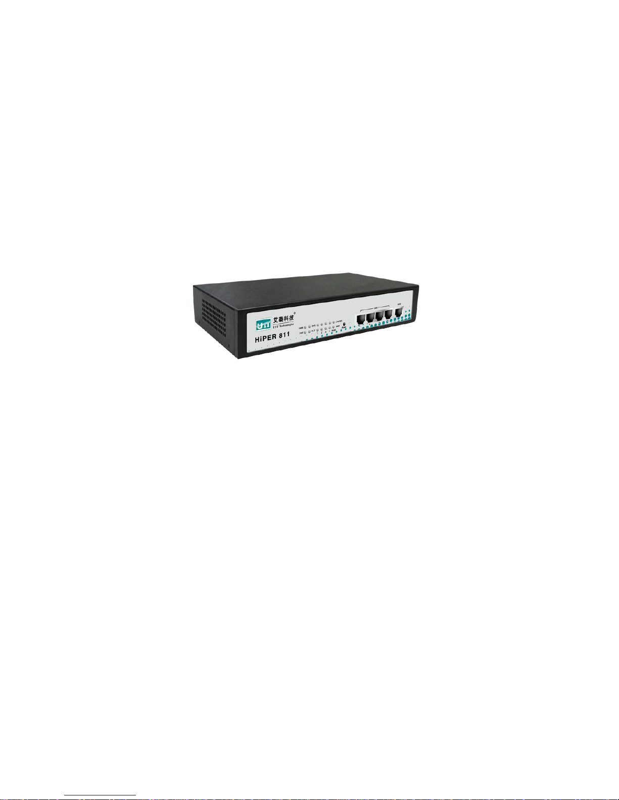
The HiPER 811 security gateway/VPN firewall is a purpose-built security system
designed for small-sized businesses and enterprise branch offices.
The HiPER 811 integrates a rich suite of functions, including L2TP/PPTP/IPSec VPN,
NAT/PAT, firewall, bandwidth management, DHCP server/client, popular attack defense
capability, system management and monitor, and so on.
1.1 Key Features
Operation mode: NAT/NAPT, route and hybrid mode
Internet connection type: PPPoE, Static IP and DHCP
Supports Express Forwarding, excellent performance
Built-in firewall,Defense against ARP spoofing, DoS/DDoS attack, port scanning,
Worm.Blaster, Worm.Sasser, etc.
Supports NAT port forwarding, DMS host
Supports NAT ALG: ICMP, FTP, GRE, PPTP, ESP ALG, etc.
Supports NAT sessions limit for each internal host
Supports bandwidth limit for each internal host
Supports IP packet filtering IP address, protocol and TCP/UDP port filtering
Supports Web content filtering: URL and keyword filtering
Filtering based on schedule
IM (instant messenger) control: block or allow IM application, e.g., MSN and QQ
Page 11

Page 6
Messenger
P2P (peer-to-peer) control: block or allow P2P application, e.g., BitTorrent and
BitSpirit
Supports personal policy settings to realize personal service according to need
Provide hierarchy management structure (include personal, group and global) to
flexibly manage the internal users
Supports IP/MAC binding, blacklist and whitelist Setting
IP/MAC intelligent binding: automatic binding and batch binding
Supports DHCP Server and Client,DHCP static binding;
Supports SNTP (Simple Network Time Protocol)
Supports DDNS (Dynamic DNS)
Supports Port-based VLAN
Supports UPnP
Supports port mirror
Supports MAC address clone
Supports static route,dynamic route protocol: RIP I and RIP II
Supports NAT traversal of IPSec, PPTP and L2TP
Provides Web user interface, Command line interface (Telnet)
Remote management via Web or CLI
Supports SYSLOG, SNMP v1 and v2c
Configuration file backup and restore
Firmware upgrade via TFTP or Web
Multi-level administration privileges
Built-in diagnostic tool: ping, traceroute, nslookup
Real-time monitoring, logging, alarms of system activities
Supports IPSec, L2TP and PPTP VPN
FQDN (fully qualified domain name) support for dynamic IP address VPN
connections
Site-to-site VPN, remote access VPN (client-to-site)
VPN pass-through of L2TP, PPTP, IPSec
L2TP server and client, PPTP server and client
Page 12

Page 7
IPSec features as followed:
1. AutoIKE based on preshared key and manual key tunnels
2. ESP and AH protocols
3. DES, 3DES and AES 128/192/256 encryption algorithm
4. MD5 and SHA-1 hash algorithm
5. Diffie-Hellman group 1, 2 and 5
6. Main mode and aggressive mode
7. DPD (dead peer detection) and Anti-Replay
8. Hub-spoke and mesh connections
1.2 Specifications
Conforms to IEEE 802.3 Ethernet and IEEE 802.3u Fast Ethernet standards
Supports TCP/IP, PPPoE, DHCP, ICMP, NAT, Static Route, RIPI/II, SNMP (MIB II),
etc.
Supports 4-port LAN switch, a WAN port, and a reset button
Supports Auto-negotiation for 10/100Mbps and duplex mode for each physical port
Supports Auto MDI/MDI-X for each physical port
Provides status LEDs
Environment:
Operating Temperature: 32ºF to 104ºF (0ºC to 40ºC)
Storage Temperature: 32ºF to 158ºF (0ºC to 70ºC)
Operating Humidity: 10% to 90%, Non-condensing
Storage Humidity: 10% to 90%, Non-condensing
Power Supply: 180V to 240V AC, 50/60Hz
Page 13
Page 8
Chapter 2 Physical Installation
This section describes how to install the Device.
2.1 Front Panel
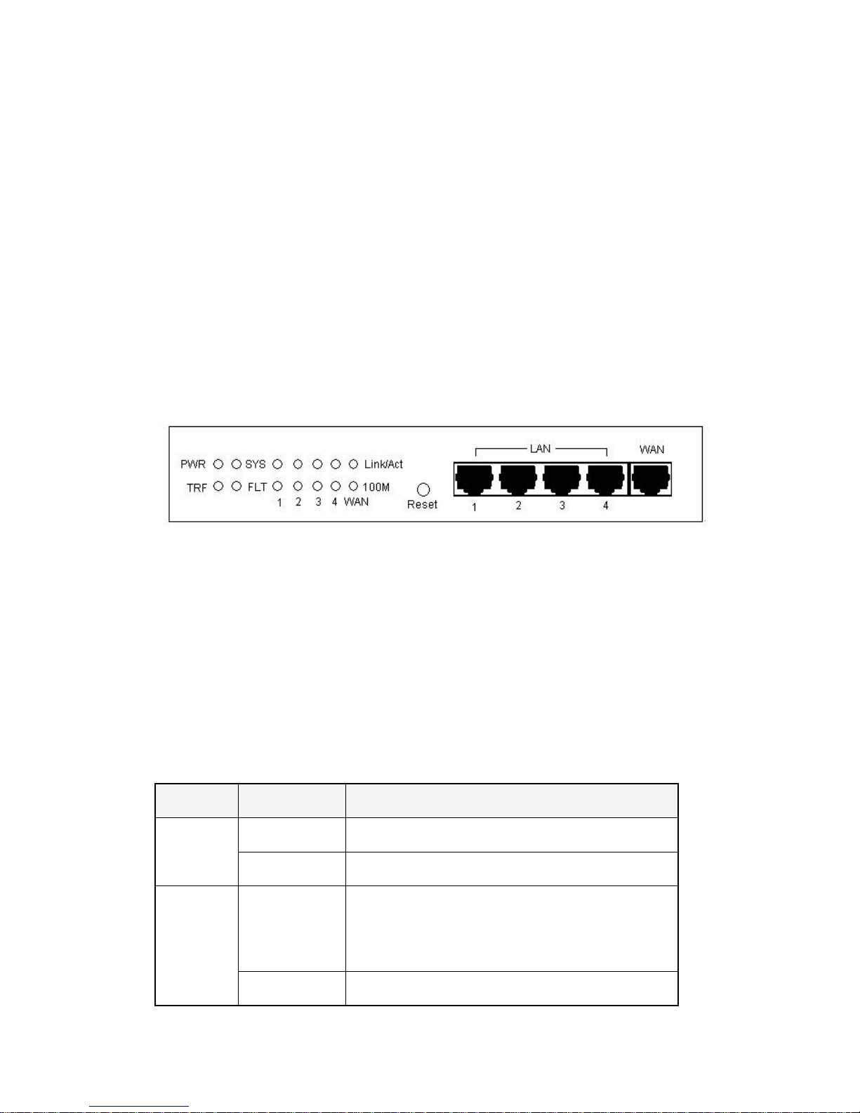
The LEDs and network ports are located on the front panel of the Device.
Figure 2-1 Front Panel
2.1.1 LEDs
The LEDs give real-time information of system status. The following table provides
description of the LEDs status and their meaning.
LED
Status
Description
PWR
Green
The Device is powered on.
Off
The Device is powered off.
SYS
Blinking
When system is working well, the status light will
blink twice per second, and it will blink slower under
heavy load.
Off or Green
Ever-on or ever-off means system is abnormal.
Page 14

Page 9
TRF
Blinking
Network activity on the Device.
Off
No activity on the Device.
FLT
Blinking
The Device is not operating correctly.
Off
The Device is operating correctly.
Link/Act
Green
Valid link on the associated port.
Blinking
Network activity on the associated port.
Off
No link established on the associated port.
100M
Green
The associated port is connected at 100Mbps.
Off
The associated port is connected at 10Mbps.
Table2-1 LEDs Description
2.1.2 Ports
Interface
Description
LAN (1, 2, 3, 4)
These Ethernet ports connect the Device to wired computers,
hubs, switches, and other Ethernet network devices.
WAN
This port connects to a cable or DSL modem, or other Ethernet
network device.
Table2-2 Ports Description
2.1.3 Reset Button
If you want to reset the Device to the factory default settings, press and hold in the Reset
button for more than 5 seconds when the Device is on, then release the button. After that,
the Device will restart with the factory default settings.
Note
Page 15

Page 10
1. The reset operation will clear all the settings and preferences that you have
configured.
2. You can also reset the Device to the factory defaults on the System Admin >
Backup & Restore page.
Page 16
Page 11
2.2 Connecting the Device
Before you install the Device, please make sure your PC can connect to the Internet
through your broadband service successfully. If there is any problem, please contact with
your ISP for help.
After that, please install the Device according to the following steps. Don’t forget to pull
out the power plug and keep your hands dry.
Step 1 Power off your PC(s), Cable/DSL modem, and the Device.
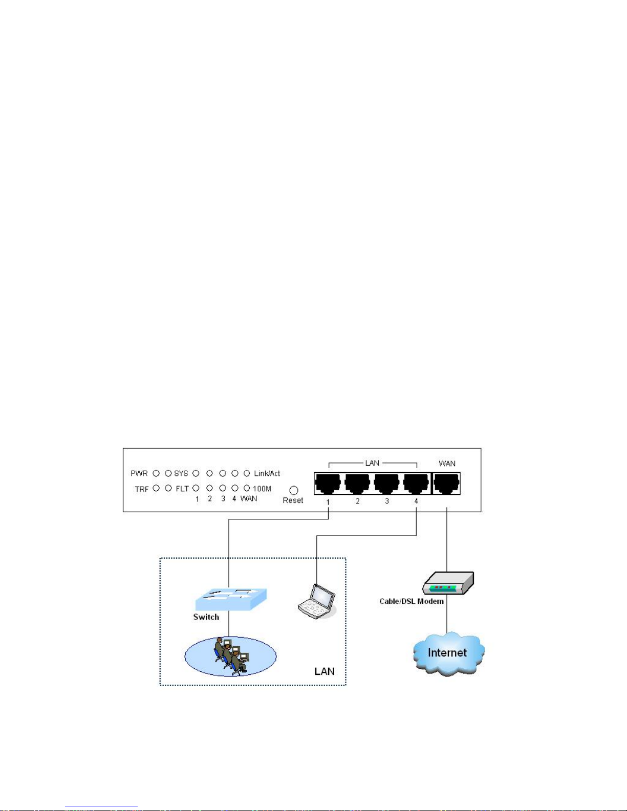
Step 2 Connect the PC(s) and the Switches or Hubs on your LAN to the Device’s LAN
port (see Figure 2-2).
Step 3 Connect the Cable/DSL modem to the Device’s WAN port (see Figure 2-2).
Step 4 Connect the power cord to the power connector on the back panel of the
Switch. Then plug the other end of the power cord to a grounded three-prong
AC power outlet. The Device will start to work automatically.
Step 5 Power on your network devices, PCs, Switches, Hubs, and so on.
Figure 2-2 Connecting the Device
Page 17

Page 12
Chapter 3 Quick Setup Guide
After you have connected the Device into your network, you may configure it. This
chapter describes how to configure the basic functions of your Device. It will only take
you a few minutes. You can access the Internet via the Device immediately after it has
been successfully configured.
3.1 Configure PC
Before set up the Device, you need to install and configure TCP/IP properties on each
network PC.
Step 1 Connect the PC to the Device’s LAN port.
Step 2 Install TCP/IP protocol components on your PC. If it has been installed, please
ignore it.
Step 3 Setup IP settings for your PC. You can setup manually or configure the PC to
obtain an IP address automatically.
Setup manually: Your PC’s IP address should be within the range from
192.168.16.2 to 192.168.16.254, the default gateway should be
192.168.16.1 (LAN interface’s IP address), and the DNS server should be
provided by your ISP.
Setup automatically: In the Internet Protocol (TCP/IP) Properties
screen, select Obtain an IP address automatically. The Device’s built-in
DHCP server will automatically assign an IP address to the PC.
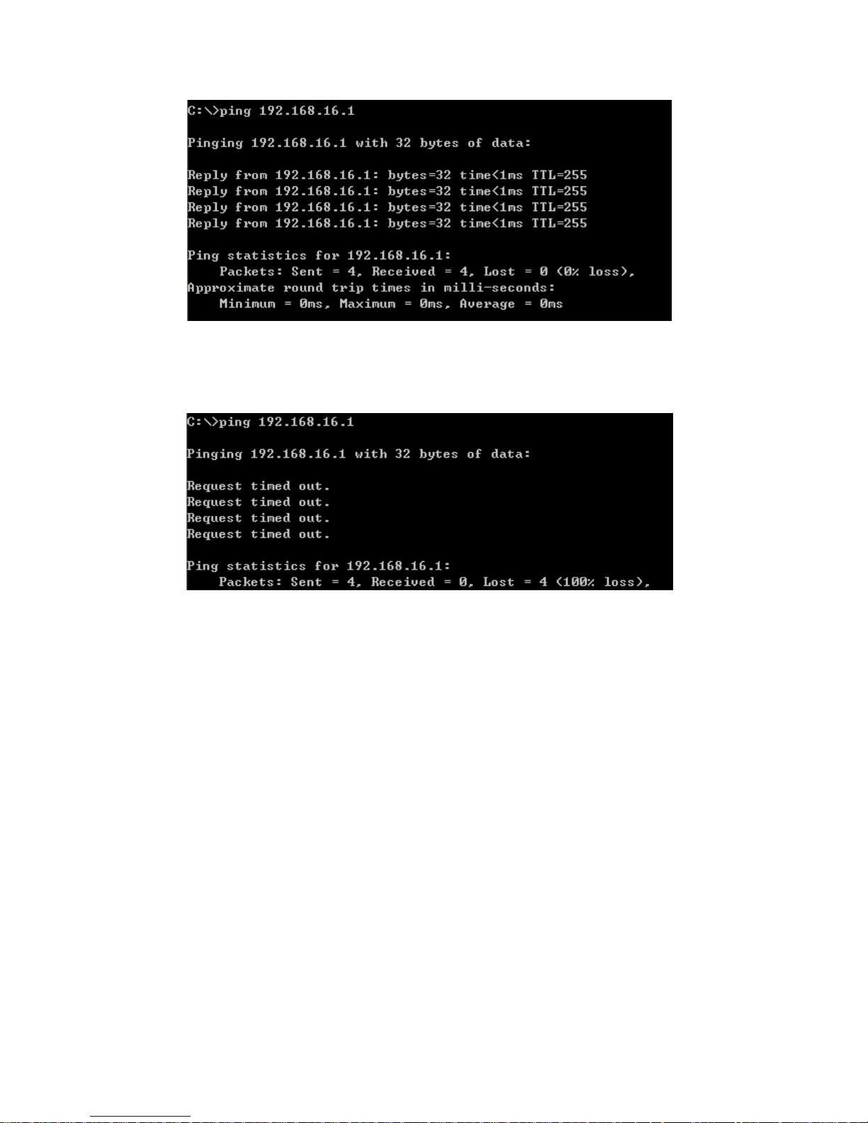
Step 4 To verify the network connection between your PC and Device, you can use
the ping command at the command prompt on the PC: Ping 192.168.16.1
If the displayed page is similar to the screenshot below, the connection
between your PC and Device has been established.
Page 18
Page 13
If the displayed page is similar to the screenshot below, it means that your
PC has not connected to the Device.
If it is failed to connect, please check it follow the steps below:
1. Is the connection between your PC and the Route correct?
The LEDs of LAN port which links to the device and the LED on your PC’s adapter
should be lit.
2. Is the TCP/IP configuration for your PC correct?
If the Device’s IP address is 192.168.16.1, your PC’s IP address should be within the
range from 192.168.16.2 to 192.168.16.254, the gateway should be 192.168.16.1.
Page 19
Page 14
3.2 Login the Device
Once your PC is properly configured, please do the following to use the Web-based
Utility.
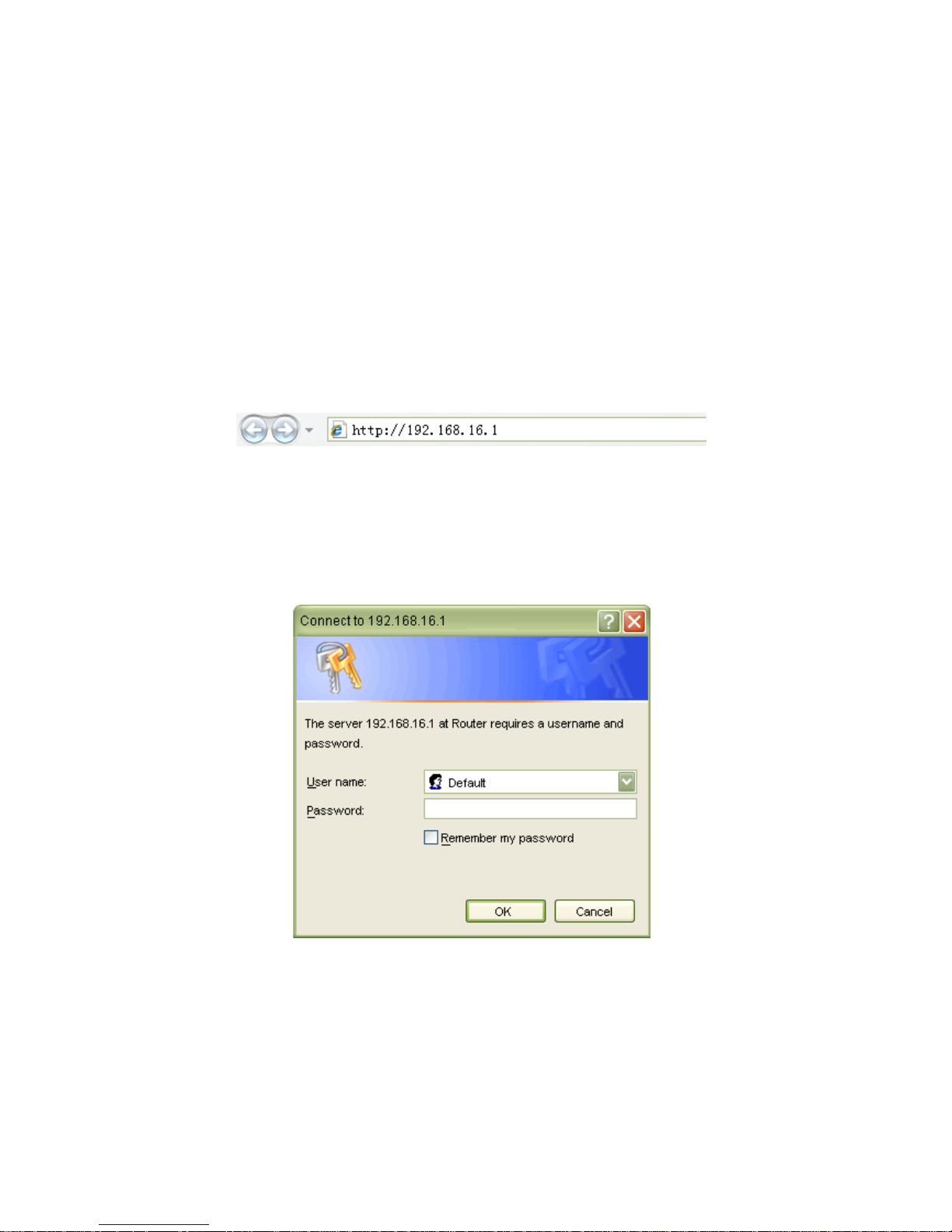
For local access of the Device’s web-based utility, launch your web browser, and enter
the Device’s default IP address: 192.168.16.1, in the RUL filed (see Figure 3-1). Then
press the Enter key.
Figure 3-1 Address Bar
A login screen prompts you for your User name and Password. Enter Default (case
sensitive) in the User name field, and keep the Password field empty (see Figure 3-2).
Then click OK.
Figure 3-2 Login Screen
Page 20
Page 15
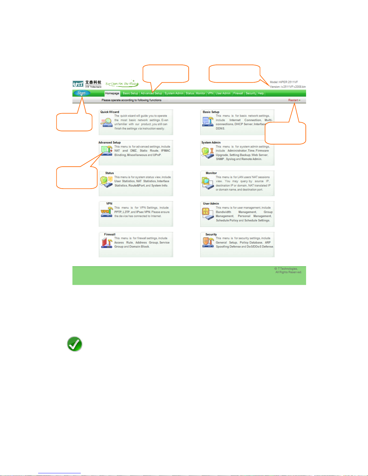
The first screen that appears is the Homepage (see Figure 3-3).
Figure 3-3 Homepage
Note
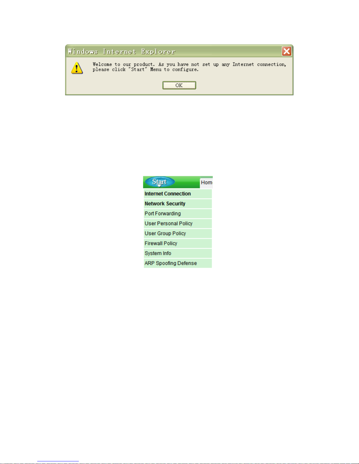
If you have not setup the Internet connection yet, the system will push a prompt dialog
box as below:
Model and Version
Start Menu
Click to Restart
the Device
Click to jump to
the related page
Level One Menu
Page 21
Page 16
Figure 3-4 A Dialog Box
Please click OK, then you can do common settings through the Start menu (see Figure
3-5), which including: Internet Connection, Network Security, Port Forwarding Rule, ARP
Spoofing Defense, User Personal Policy, User Group Policy, Firewall Policy and System
Info.
Figure 3-5 Start Menu
Page 22

Page 17
3.3 Internet Connection
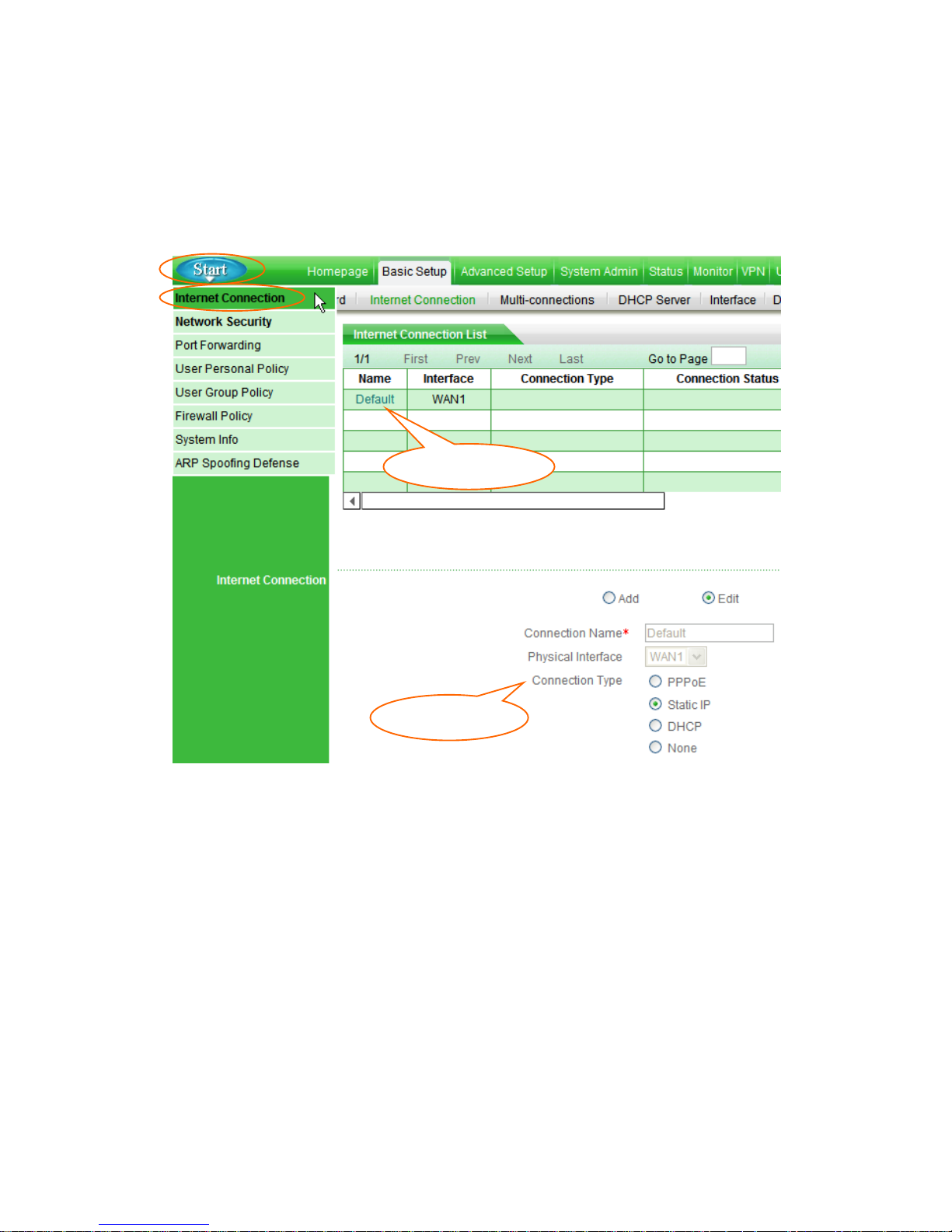
Click Start > Internet Connection,it will jump to Basic Setup > Internet Connection
page. This page lets you setup the Internet Connection, view its status, and modify or
delete it.
Note
1. When you have finished the Internet connection setup, it is strongly recommended
that you go to Start > Network Security page to do essential security settings.
2. If you change the IP address of the LAN interface during the connection setup, you
should use a new address to login to the Device. And the default gateway of each
LAN PC should use this new address to access Internet.
3.3.1 Internet Connection Setup
At first, please click the Default hyperlink of the connection entry in the Internet
Connection List (see Figure 3-6).
Then select Connection Type provide by your ISP.
Connection Name: The connection name is Default, which is reserved by system.
You can’t modify it.
Physical Interface: The Default connection is bound to the WAN interface, you
can’t modify it.
Connection Type: Select connection type from the radio boxes, which is provided
by your ISP, available options: PPPoE, Static IP and DHCP (Obtain an IP
automatically).
PPPoE: Some DSL-based Internet Service Providers (ISPs) use PPPoE
(Point-to-Point Protocol over Ethernet) to establish Internet connections for
end-users. If you use a DSL line, check with your ISP to see if they use PPPoE,
Page 23
Page 18
and then select PPPoE;
Static IP: If you are required to use a permanent IP address, select Static IP;
DHCP: If your ISP automatically assigns an IP address, select DHCP. Most
cable modem subscribers use this connection type.
Figure 3-6 Select Connection Type
Depending on which connection type you select, you will see various settings. We will
describe the settings for each connection type respectively (see chapter 3.3.1.1, 3.3.1.2
and 3.3.1.3).
② Select Type
① Click Default
Page 24
Page 19
3.3.1.1 PPPoE Connection
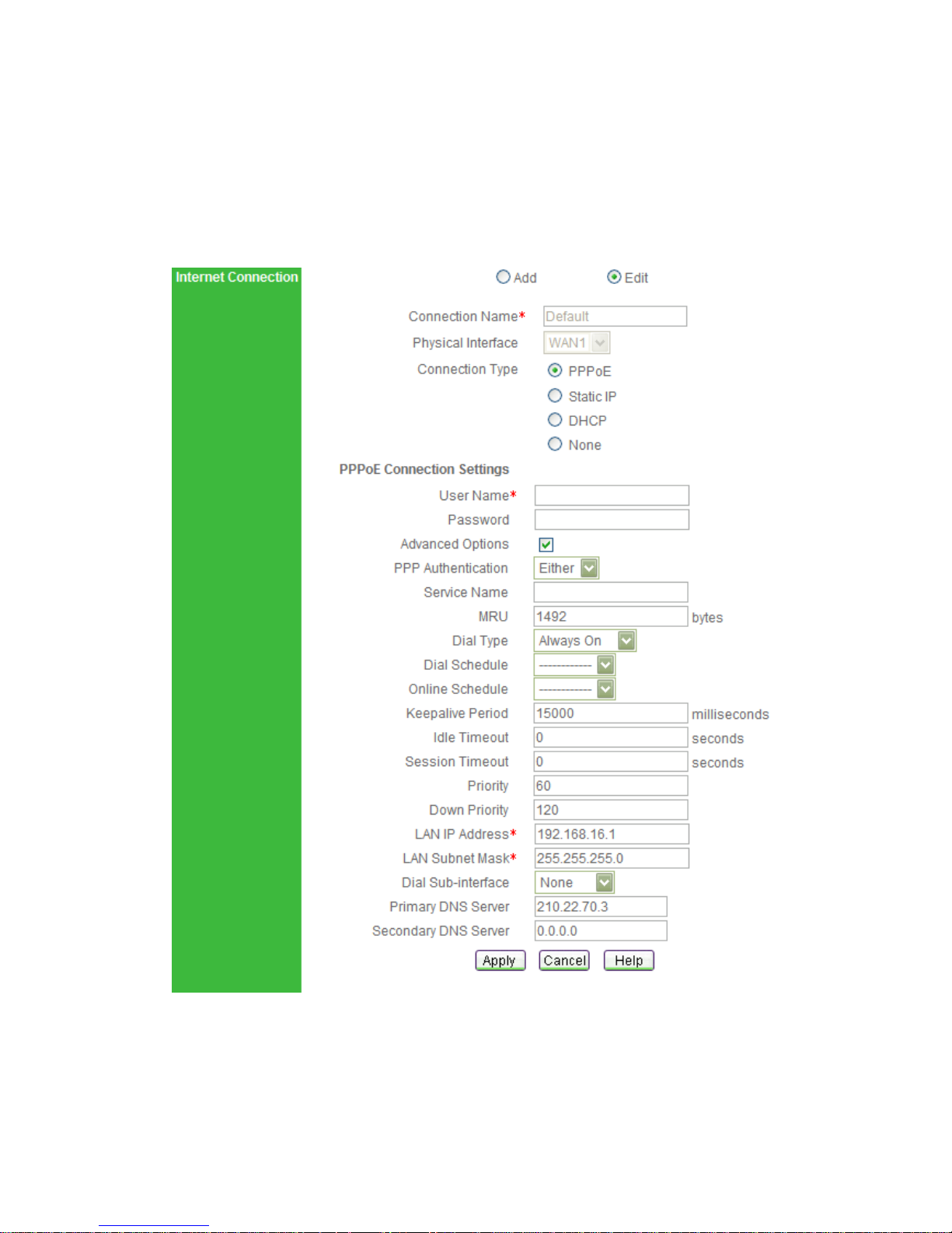
If you choose PPPoE connection type, you will see the following page.
Figure 3-7 PPPoE Connection Setup
User Name and Password: Enter the PPPoE login user name and password
provided by your ISP.
Page 25

Page 20
PPP Authentication: Select PPP authentication mode from this drop-down box,
available options: NONE, PAP, CHAP and Either.
PAP: Password Authentication Protocol;
CHAP: Challenge Handshake Authentication Protocol;
None: It means that there is no protocol will be used.
Either: It means that the Device will automatically negotiate it with the peer
device.
LAN IP Address: Enter the IP address for the Device’s LAN interface.
LAN Subnet Mask: Enter the subnet mask for the Device’s LAN interface.
Primary DNS Server: Enter the IP address of your ISP’s primary DNS server.
Secondary DNS Server: Enter the IP address of your ISP’s secondary DNS server
if it is available.
Advanced Options: Select this check box to configure advanced parameters. In
most case, you need not configure them.
Service Name: Enter the Service Name, if provided by your ISP.
MRU: The MRU (Maximum Receive Unit) setting specifies the largest packet size
permitted for network receive. In most cases, keep the default value (1492). When
dialing, the Device will automatically negotiate it with the peer device.
Dial Type: Select type of dial connection from this drop-down box, available options:
Always On, Manual and On Demand.
Always On: If you want the Device to establish a PPPoE session when starting
up and to automatically re-establish the PPPoE session once disconnected,
select this option.
Manual: If you want to dial and hang up a PPPoE session manually, select this
option. In the case of Manual type, you should dial and hang up manually in the
Internet Connection List on Basic Setup > Internet Connection page (See
chapter 3.3.3).
On Demand: If you want the Device to establish a PPPoE session only when
there are packets requesting to access the Internet (i.e., when a program on
your computer attempts to access the Internet), select this option.
Page 26

Page 21
Dial Schedule: If you select a schedule (set up on User Admin > Schedule
Settings page), it will allow your Device to dial-up only in the selected schedule
range. Else, the Device always can dial-up.
Online Schedule: If you select a schedule rule (set up on User Admin > Schedule
Settings page), your Device can keep the Internet connection active only in the
online schedule range. Else, the connection always can keep active.
Keepalive Period: When the Internet connection is connected, the Device will
periodically send keepalive packets to the peer device per 1000 milliseconds. If the
Device does not receive a response during a specified period (set by Keepalive
Period), it will terminate the connection.
Idle Timeout: This determines how long the Device keeps the Internet connection
active after no Internet activity. If you set the value to zero, the Device will not
terminate it.
Session Timeout: This determines how long the Device keeps the Internet
connection active since connected. If you set the value to zero, the Device will not
disconnect it.
Priority: It specifies the routing priority for connected connection. When there are
several connections having the same destination subnet, the Device will choose the
connection having the highest priority to transmit the packets. The lower value
means the higher priority.
Down Priority: It specifies the routing priority for disconnected connection. When
there are several connections having the same destination subnet, the Device will
choose the connection having the highest priority to dial-up. The lower value means
the higher priority.
Dial Sub-interface: This Device doesn’t support it.
Page 27
Page 22
3.3.1.2 Static IP Connection
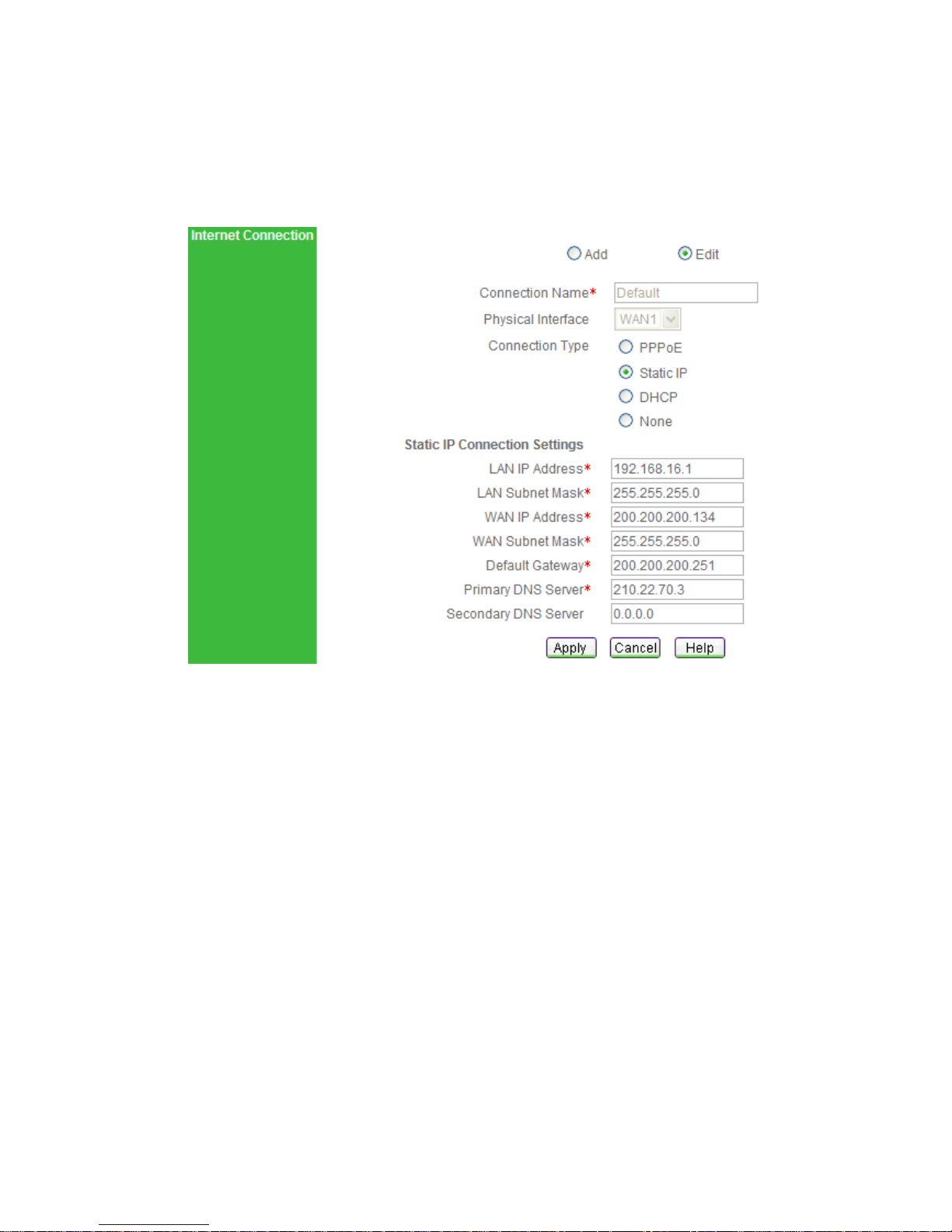
If you choose Static IP connection type, you will see the following page.
Figure 3-8 Static IP Connection Setup
LAN IP Address: Enter the IP address for the Device’s LAN interface.
LAN Subnet Mask: Enter the subnet mask for the Device’s LAN interface.
WAN IP Address: Enter the IP address for the Device’s WAN interface, which is
provided by your ISP.
WAN Subnet Mask: Enter the subnet mask for the Device’s WAN interface, which is
provided by your ISP.
Default Gateway: Enter the IP address for the default gateway, which is provided
by your ISP.
Primary DNS Server: Enter the IP address of your ISP’s primary DNS server.
Secondary DNS Server: Enter the IP address of your ISP’s secondary DNS server
if it is available.
Page 28
Page 23
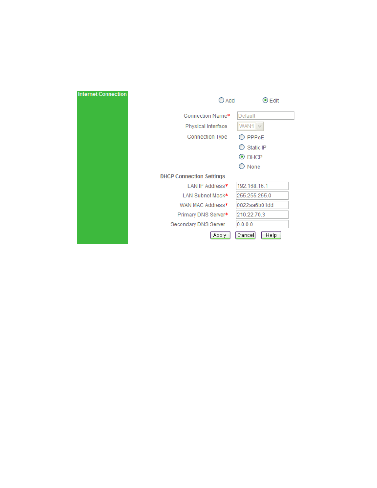
3.3.1.3 DHCP Connection
If you choose DHCP connection type, you will see the following page.
Figure 3-9 DHCP Connection Setup
LAN IP Address: Enter the IP address for the Device’s LAN interface.
LAN Subnet Mask: Enter the subnet mask for the Device’s LAN interface.
WAN MAC Address: This field displays the current MAC address of the WAN
interface. In most cases, you need not change it. But when using DHCP connection
type, your ISP may only allow one MAC address to be registered. To bypass this
restriction, you should enter the registered MAC address that is stored by your ISP.
Primary DNS Server: Enter the IP address of your ISP’s primary DNS server.
Secondary DNS Server: Enter the IP address of your ISP’s secondary DNS server
if it is available.
Page 29
Page 24
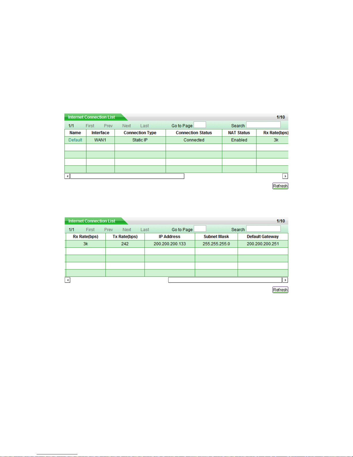
3.3.2 Internet Connection List
When you have configured the Default connection, you can view its status in the Internet
Connection List (see Table 3-1).
To view current status of the connection, click Refresh button.
Table 3-1 Internet Connection List
Table 3-1 Internet Connection List (continued)
Name: It displays the connection’s name.
Interface: It displays the name of the physical interface to which the connection is
bound.
Connection Type: It displays the connection’s type. In the case of PPPoE type, it
will also display the user name.
Connection Status: It displays current status of the connection. We will describe
each connection type respectively.
Page 30

Page 25
1. PPPoE Connection Status
There are eight kinds of status for PPPoE connection (see Table 3-2). During it is in
connected status, it will also display the elapsed time (day: hour: minute: second)
since connected.
Status
Description
Closed
The physical interface is inactive, or not dial-up.
Dialing
Start dialing up, but not receive response yet.
Authenticating
Server responded and is authenticating.
Connected
Authenticated succeed, and the connection is established
and ready for date transmit.
Disconnecting
The PPPoE session is disconnecting.
Hang up
Either peer has hanged up.
Disconnected
PPPoE session has terminated, waiting for dialing up.
Internal Error
Undefined status.
Table 3-2 Description of Connection Status – PPPoE
2. Static IP Connection Status
There are three kinds of status for Static IP connection (see Table 3-3).
Status
Description
Closed
The physical interface is inactive.
Connected
The connection is established between the local and peer
devices.
Internal Error
Undefined status.
Table 3-3 Description of Connection Status – Static IP
3. DHCP Connection Status
There are three kinds of status for DHCP connection (see Table 3-4). During it is in
connected status, it will also display the time left before the lease expires (day: hour:
minute: second) for current IP address, which is assigned by your ISP’s DHCP
server.
Page 31

Page 26
Status
Description
Closed
The physical interface is inactive, or the connection has
release the IP address but not request a new one yet.
Connecting
Requesting an IP address.
Connected
Have acquired an IP address, the connection is established.
Internal Error
Undefined status.
Table 3-4 Description of Connection Status – DHCP
NAT Status: It displays whether the connection enable NAT function or not. The
system will automatically enable NAT function during connection setup.
Rx Rate(bps): It displays current download rate of the connection during the refresh
interval.
Tx Rate(bps): It displays current upload rate of the connection during the refresh
interval.
IP Address, Subnet Mask and Default Gateway: They display the IP settings
status of the Device as seen by the external users of the Internet.
If your connection type is PPPoE or DHCP, it will show the information currently
being used, which received from your ISP’s PPPoE or DHCP server.
If your connection type is Static IP, the information will be the same as your
input.
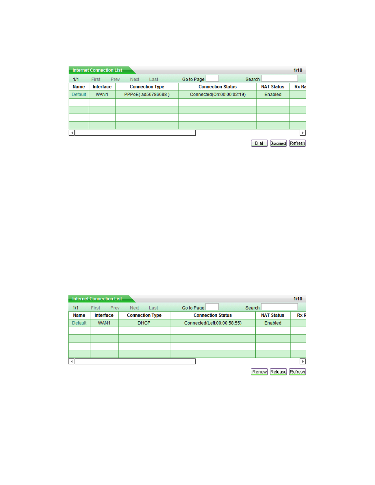
3.3.3 How to Dial and Hang up a PPPoE connection
If your connection type is PPPoE, when you click the Default hyperlink of the connection
entry, the Dial, Disconnect and Refresh buttons will show below the list (see Table 3-5).
Note
If you have chosen Manual as Dial Type for your PPPoE connection (see chapter
3.3.1.1), you need click Dial button to dial-up the Internet connection, and click
Disconnect button to hang it up here.
Page 32
Page 27
Click Refresh button to view current status of the connection.
Table 3-5 Internet Connection List - PPPoE Connection
3.3.4 How to Renew and Release a DHCP Connection
If your connection type is DHCP, when you click the Default hyperlink of the connection
entry, the Renew, Release and Refresh buttons will show below the list (see Table 3-6).
Click Renew button to re-acquire an IP address from the ISP’s DHCP server.
Click Release button to release the IP address obtained from the ISP’s DHCP server.
Click Refresh button to view current status of the connection.
Table 3-6 Internet Connection List - DHCP Connection
Page 33
Page 28
3.3.5 How to Edit the Connection
If you want to edit the connection, do the following:
Step 1 In the Internet Connection List, click the Default hyperlink of the connection
entry, the related information will display in the setup fields.
Step 2 Modify the connection settings.
Step 3 Click Apply button to save and apply your settings.
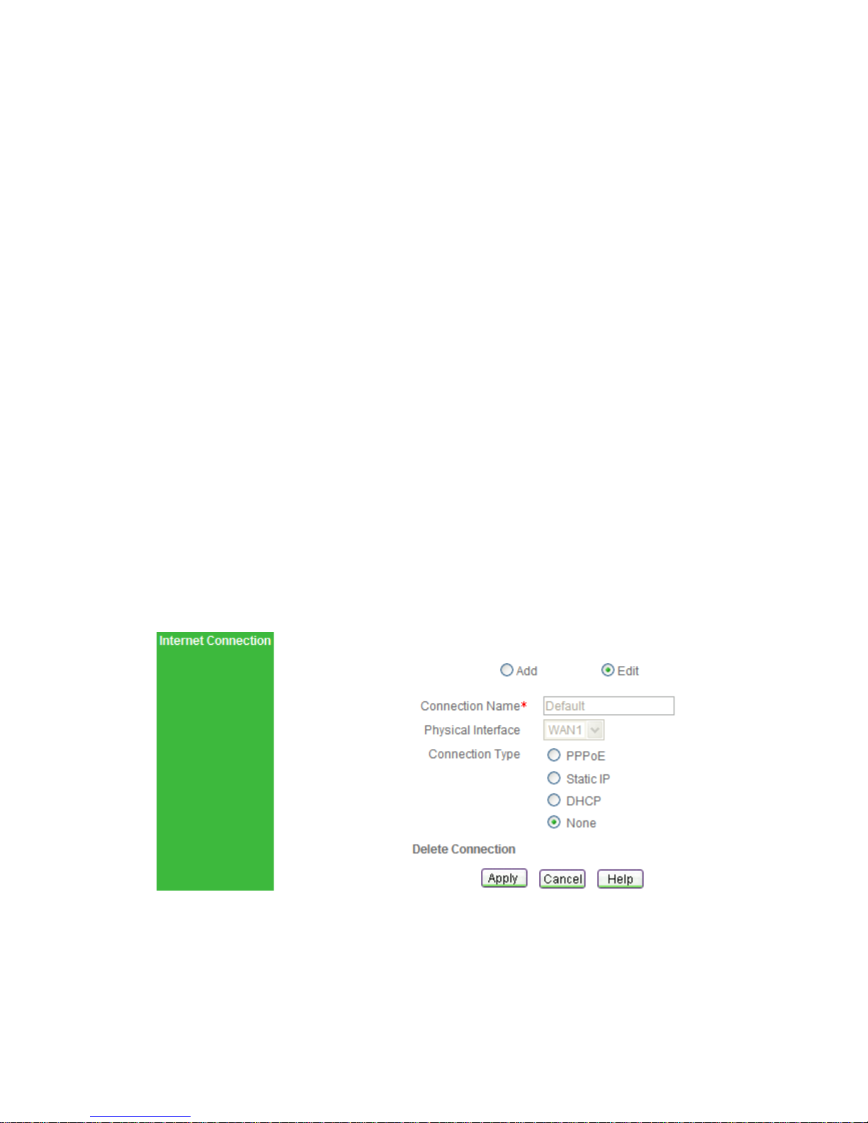
3.3.6 How to Delete the Connection
If you want to delete the connection, do the following:
Step 1 In the Internet Connection List, click the Default hyperlink of the connection
entry, the related information will display in the setup fields.
Step 2 In the Connection Type radio boxes, select none (See Figure 3-10).
Step 3 Click Apply button to delete the connection.
Figure 3-10 Delete the Connection
Page 34
Page 29
3.4 Network Security
On the Start > Network Security page, you can do essential security settings: virus
defense and rate limit. You can’t go to this page if the Internet connection hasn’t been
configured yet.
Note
When you click Apply button to save and apply your settings, the system will
automatically enable the Synchronize with SNTP Server function (you also can setup it
in System Admin >Time page), so it will acquire standard time once connected to
Internet.
3.4.1 Virus Defense
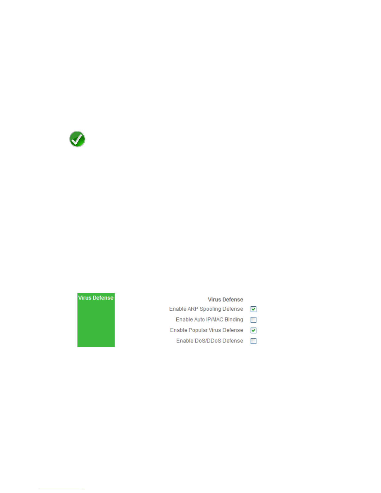
In this section (see Figure 3-11), you can do basic security settings to effectively defense
ARP spoofing attack, Dos and DDoS attack, and popular virus attack (e.g., Worm.Blaster
and Worm.Sasser). It will make your network robust and security.
Figure 3-11 Virus Defense
Enable ARP Spoofing Defense: To protect the Device against ARP spoofing attack
effectively, select this check box, and then bind all IP/MAC address pairs of the
whole LAN PCs (setup on Security > ARP Spoofing Defense, see chapter 3.5.2).
Enable Auto IP/MAC Binding: If you select this check box, it will periodically detect
active hosts connected to the device, and immediately bind all of the new valid
dynamic ARP information (IP and MAC address pairs) once learned them.
Page 35
Page 30
Enable Popular Virus Defense: Select this check box to protect the device against
popular virus attack, e.g., Worm.Blaster and Worm.Sasser. And it will discard those
TCP packets whose destination port is 135, 136, 137, 138, 139, 445, 1025, 5554 or
9996, so your LAN hosts can’t access related services provided by outside hosts,
e.g., windows file sharing and print sharing services.
Enable DoS/DDoS Attack Defense: Select this check box to protect the device
against popular DoS and DDoS attack.
Note
If your LAN hosts’ IP addresses often change, it is recommended that you don’t select
Enable Auto IP/MAC Binding. If you want to manually bind IP and MAC address pairs,
please go to Security > ARP Spoofing Defense page to setup (see chapter 3.5.2).
3.4.2 Rate Limit
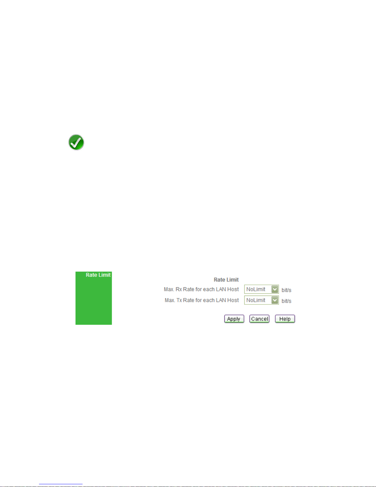
In this section, you can specify a bandwidth limit for each LAN host. This function lets
you allocate bandwidth equally to avoid few hosts occupying too much bandwidth.
Figure 3-12 Rate Limit
Max. Rx Rate for each LAN Host: Select the maximum download rate for each
LAN host. If you don’t want to limit the download rate, select NoLimit. If you want to
block internal users from downloading, select Block.
Max. Tx Rate for each LAN Host: Select the maximum upload rate for each LAN
host. If you don’t want to limit the upload rate, select NoLimit. If you want to block
internal users from uploading, select Block.
Page 36
Page 31
3.5 ARP Spoofing Defense
Click Start > ARP Spoofing Defense,it will jump to Security > ARP Spoofing
Defense page. This page lets you setup ARP Spoofing Defense to protect the device
and your LAN hosts.
3.5.1 ARP Spoofing Defense Setup
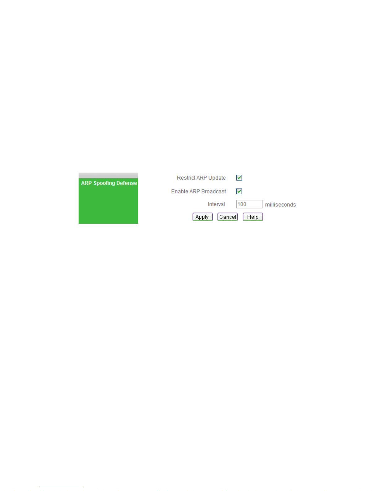
Figure 3-13 ARP Spoofing Defense
Restrict ARP Update: Select this check box to disable the gratuitous ARP packets
learning function, so the device will discard gratuitous ARP packets directly. This
function will effectively protect the device against ARP spoofing attack.
Enable ARP Broadcast: Select this check box to enable the device to periodically
broadcast gratuitous ARP packets, it will inform your LAN hosts the correct MAC
address of the device’s LAN interface. This function will effectively protect your LAN
hosts against ARP spoofing attack.
Interval: Specify the interval between Gratuitous ARP packets (how often you want
the packets to be broadcast). It should be a multiple of 10 between 100 and 5000
(milliseconds).
3.5.2 Dynamic ARP Table
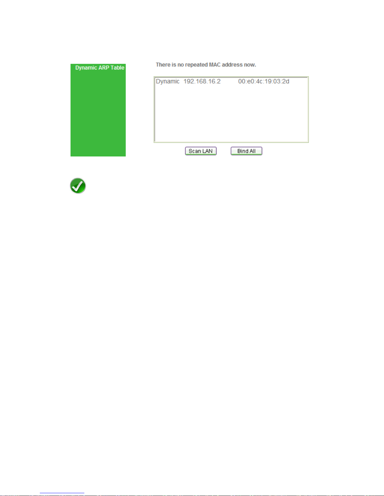
Click Scan LAN button (see Figure 3-14), it will automatically detect active hosts
connected to the device, learn and display dynamic ARP information (IP and MAC
address entries).
Page 37
Page 32
Click Bind All button to bind all current valid IP and MAC address pairs.
Figure 3-14 Dynamic ARP Table
Note
1. If you want to bind all IP and MAC address pairs in the whole LAN, please make
sure that the hosts are turned on, and then click Scan LAN button, last click Bind
All button.
2. If you click Scan LAN button, the system will also check if there are any repeated IP
or MAC addresses in the Dynamic ARP Table, and then display repeated
information above it: repeated MAC addresses indicate that potential ARP spoofing
attack existing in your LAN, and repeated IP addresses indicate that potential IP
spoofing attack or IP address conflicting existing in it.
3.5.3 How to Defense Against ARP Spoofing Attack
To defense against ARP Spoofing Attack, do the following:
Step 1 Select both Restrict ARP Update and Enable ARP Broadcast check boxes.
Step 2 Turn on all of the hosts in your LAN, and then click Scan LAN button to learn
current dynamic ARP information.
Step 3 Click Bind All button to bind all current valid IP and MAC address pairs.
When you have finished these steps, it will protect the device and your LAN hosts
against ARP Spoofing Attack.
Page 38
Page 33
3.6 Port Forwarding
Click Start > Port Forwarding, it will jump to Advanced > NAT & DMZ page. In this
page, you can setup some port forwarding rules.
Port forwarding can be used to set up public services on your network. When users from
the Internet make certain requests on your network, the Device can forward those
requests to computers equipped to handle the requests. For example, if you set the port
number 443 (HTTPS) to be forwarded to IP address 192.168.16.12, then all HTTPS
requests from outside users will be forwarded to 192.168.16.12.
3.6.1 Port Forwarding Setup
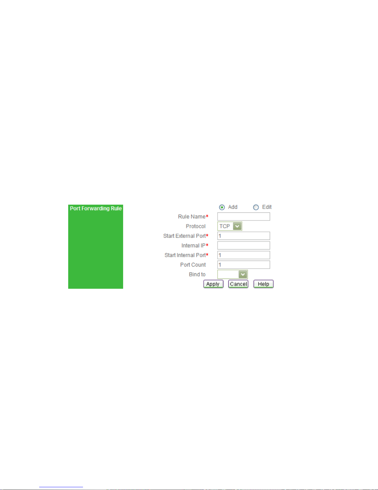
Figure 3-15 Port Forwarding Setup
Rule Name: Enter a name. It should be between 1 and 11 characters long.
Protocol: Select the protocol which it uses, available options: TCP, UDP and GRE.
Start External Port: Enter the lowest port number, which the Device provides for
outside users to access.
Internal IP: Enter the IP address of the local server that you want outside users to
access.
Start Internal Port: Enter the lowest port number used by the service.
Port Count: Enter the number of ports used by the service. If the service uses only
one port number, enter 1. The maximum value is 20. For example, if the start
internal port is 21, the start external port is 2000 and the port count is 10, then the
Page 39
Page 34
internal port range is from 21 to 30, and the external port range is from 2001 to
2010.
Bind to: Select the NAT rule to which this port forwarding rule is bound. The port
forwarding rule will use the NAT rule’s external IP address as the external IP
address.
Note
1. If you select GRE protocol, the start external port and start external port should be 0,
and the port count should be 1.
2. The system will automatically create some port forwarding rules. You can not modify
or delete them.
3.6.2 Port Forwarding Rule List
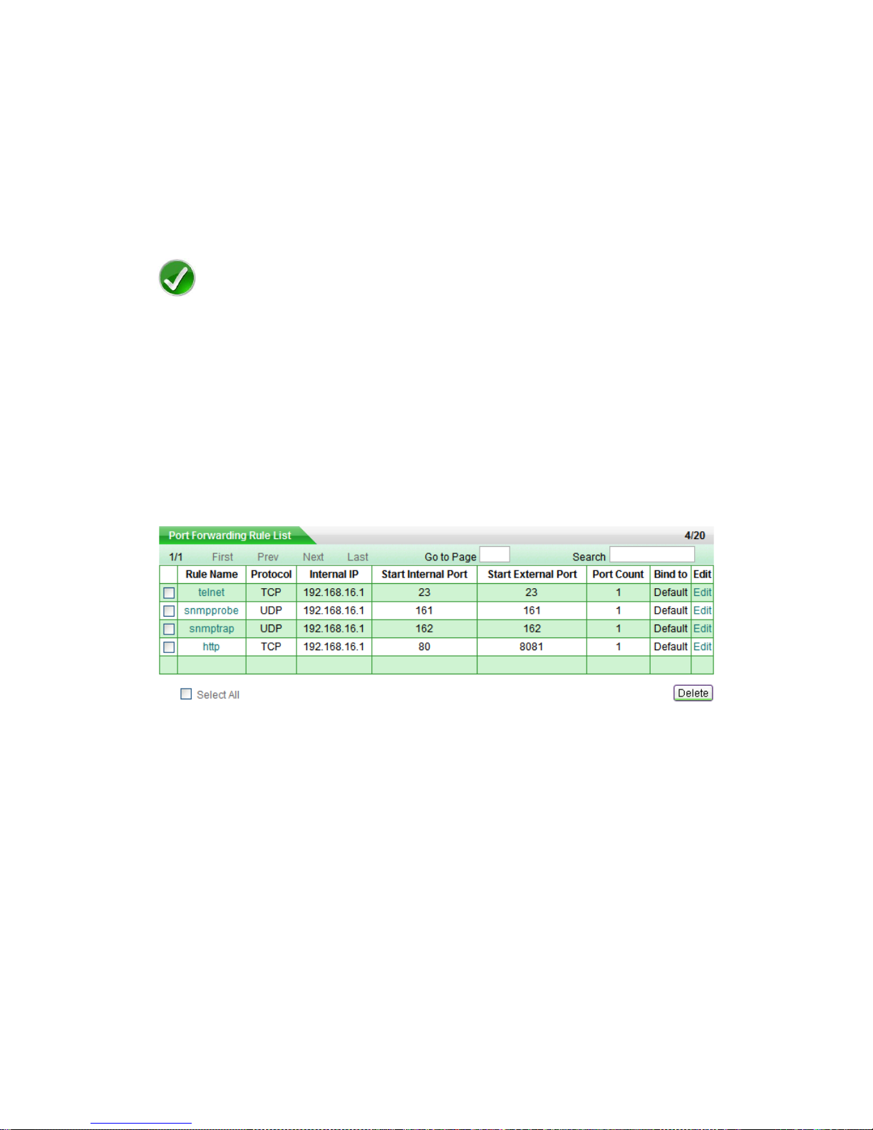
Table 3-7 Port Forwarding Rule List
Add a Port Forwarding Rule: If you want to add a port forwarding rule, select Add
radio box, and then setup it, last click Apply button.
View Port Forwarding Rules: When you have created some port forwarding rules,
you can view them in the Port Forwarding Rule List.
Edit a Port Forwarding Rule: If you want to modify a port forwarding rule you have
created, click the Rule Name or Edit hyperlink of this rule entry, the related
information will display in the setup fields, and then modify it, last click Apply button.
Delete Port Forwarding Rule(s): If you want to delete some port forwarding rules,
select the leftmost check boxes of these entries, and then click delete button.
Page 40
Page 35
3.7 Change Administrator’s Password
The default administrator’s user name is Default (case sensitive) with empty password.
To ensure the Device's security, you had better change the default password and
remember it. If the password has been changed, you should enter your new password
when you access the Device with the user name Default.
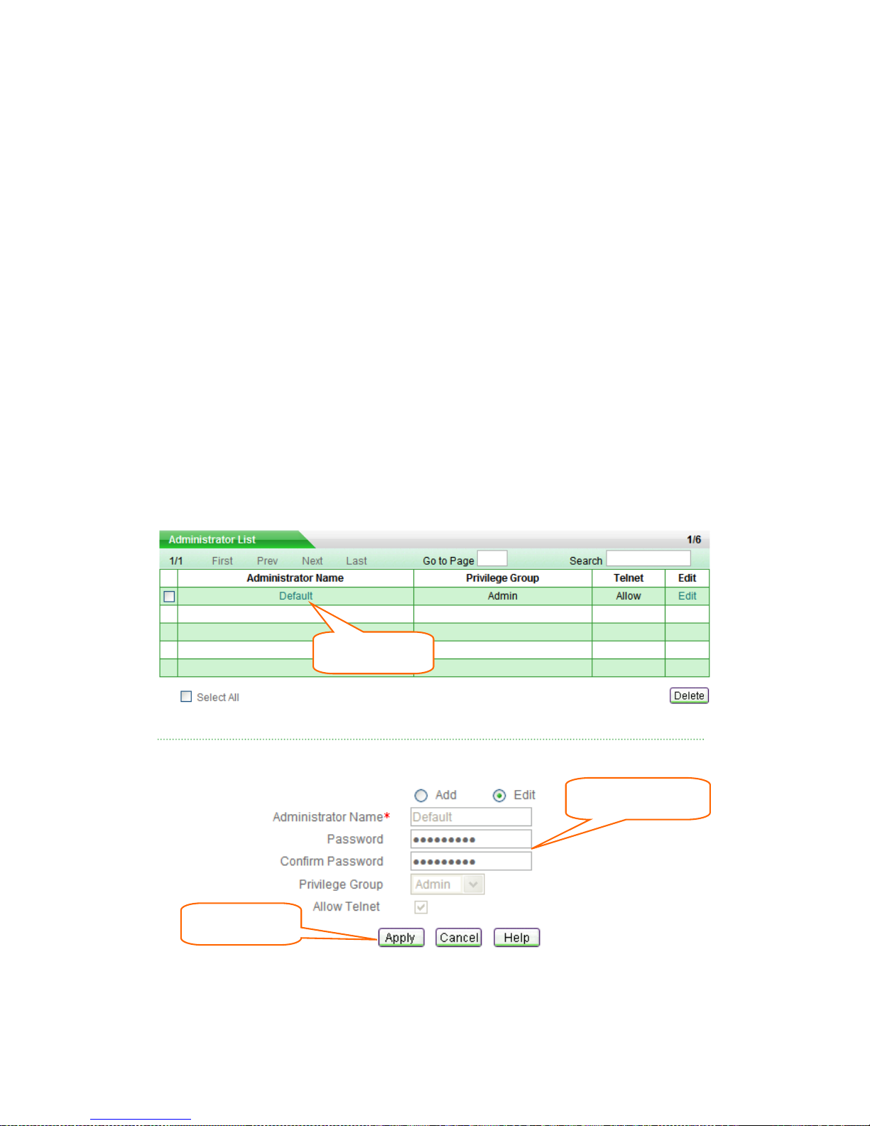
If you want to change the password, go to System > Administrator page, do the
following setup (see Figure 3-16):
Step 1 Click the Default or Edit hyperlink of the default administrator’s entry in the
Administrator List, the related information will display in the setup fields.
Step 2 Then modify the password in the setup fields.
Step 3 Click Apply button to save and apply your settings.
Figure 3-16 Administrator’s Password Setup
① Click Default
② Modify password
③ Click Apply
Page 41
Page 36
3.8 Remote Management
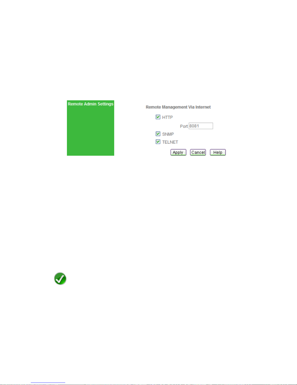
If you want to allow HTTP, SNMP or TELNET remote management via Internet, go to
System Admin > Remote Admin page to setup.
Figure 3-17 Remote Management
HTTP: Select this check box to allow HTTP remote management. When accessing
the Device from Internet, you will enter http:// and enter the Device's WAN IP
address, followed by a colon (:) and the port number. For example, if WAN IP
address is 218.21.31.3 and the port number is 8081, enter in your browser:
http://218.21.31.3:8081.
Port: Enter the port number for HTTP remote management. The default value is
8081.
SNMP: Select this check box to allow SNMP remote management via Internet.
TELNET: Select this check box to allow TELENET remote management via Internet.
Note
To ensure security, it is strongly recommended that you don’t enable remote
management functions unless necessary. If you are sure to enable them, you had better
change the default password.
Page 42

Page 37
Appendix Contact Information
For help with the installation or operation of this Device, contact UTT Technical Support
at one of the phone numbers or Internet addresses below.
Technical Support: +86-4006-781-781
Official Website: http://www.utt.com.cn
Official BBS: http://www.utt.com.cn/bbs
Fax: +86-21-52655269
 Loading...