

Page 1
Wireless Local Loop
RPC/RP Installation &
Configuration Manual
WLL-RPC/RP-IN/UM-1.0
June 19, 2000
Page 2

RPC/RP Manual
ii
Compiled by (Joseph) Guangping Zhang
Copyright 2000 UTStarcom Inc. All Rights Reserved.
This manual has been prepared for UTStarcom customers, UTStarcom personnel,
and licensees. The information contained herein is the property of UTStarcom
Inc. and shall be neither reproduced nor utilized in any form or by any means,
electronically or mechanically, in whole or in part, without prior written approval
from UTStarcom Inc.
WLL-RPC/RP-IN/UM-1.0 19June2000
Page 3

RPC/RP Manual
iii
Important Safety Instructions
Safety Information:
Installer and User WARNING
The device is to be installed and operated at a “fixed location”. The term
"fixed location" means that the device is physically secured at one location
and is not able to be easily moved to another location.
It must be located - (for indoor RPs) up on or near the ceiling away from
users or bystanders – (for outdoor RPs) on the roof top site, pole, building, or
traffic light away from users or bystanders. It must be mounted in a manner
to ensure that a minimum separation distance of 20cm is normally
maintained between all users, bystanders and the antenna (including any
radiating structure).
!
The installer may be required to perform an MPE evaluation and an
Environmental Assessment (EA) of the location at the time of licensing per
CFR 47 Part 1.1307. Fixed mounted antennae that are co-located with other
antennae must satisfy the co-location re quirements of Part 1.1307.
Limits:
The limit for general population/uncontrolled environment exposures is 1
2
/cmmW for the band 1895-1910 MHz.
MPE evaluation:
The following calculations are provided for the more restrictive limit:
uncontrolled environment/general population.
The calculated minimum safe distance, Radii(cm), is approximately 10 times
lower than the minimum required installation distance of 20 cm per Part 2.1091.
19June2000 WLL-RPC/RP-IN/UM-1.0
Page 4
RPC/RP Manual
iv
Therefore, the transmitter model numbers EA7H74B and EA7H75B complies
with the MPE requirements by providing a safe separation distance between the
antenna (including any radiating structure) and any persons.
The calculations were performed using formulas found in OET Bulletin 65
Edition 97-01(1997).
Transmitter Specifications:
Antenna
Type
Directional
Gain (dBi) Output
2.4 21.4 19 dBm (Peak) EA7H74B 20 Built-in
2.4 12.4 10 dBm (avg) EA7H74B 20
7 26 19 dBm(Peak) EA1H75B 20 Omni-
7 17 10 dBm (avg) EA1H75B 20
MPE Radii (m) For general population/uncontrolled environment
Power P(W) Max. Peak Antenna G numeric Radii(cm)
0.08 1.7 1.5 EA7H74B
0.08 5.0 2.5 EA1H75B
General Safety Instructions:
• The sign on the top right corner is intended to alert the user the presence of
important operation and maintenance (service) instructions in the literature
accompanying the product. Also notice warnings such as “WARNING!” or
“CAUTION.”
power EIRP
(dBm)
Output Power
(dBm)
Base
stations M/N
Minimum
Installation
Distance
(cm)
Base stations M/N
• When installing, operating, or maintaining the system, please follow the basic
safety procedures in order to reduce the risk of fire, electric shock, and injury to
persons, as listed below:
• Read and understand all instructions.
• Follow all warnings and instructions marked on this product.
• For information on proper mounting instructions, consult the Installation Manual
provided with this product.
• Install only equipment identified in the Installation Manual provided with this
product. Use of other equipment may result in improper connection of circuitry
leading to fire or injury to persons.
WLL-RPC/RP-IN/UM-1.0 19June2000
Page 5

RPC/RP Manual
v
• The telecommunication interfaces should not leave the building unless connected
• This product should only be operated from the type of power source indicated on
• This equipment must be provided with a readily accessible disconnect device as
• Installation must include an independent frame ground drop to building ground.
• Do not use this product near water, for example in a wet basement.
• Do not place this product on an unstable cart, stand, or table. The product may
• Use caution when installing or modifying telecommunications lines.
to telecommunication devices providing primary and secondary protection, as
applicable.
the marking label.
part of the building installation.
Refer to installation instructions.
fall, causing serious damage to the product.
• Never install telecommunications wiring during a lightning storm.
• Never install telecommunications in wet locations.
• Never touch uninsulated telecommunications wires or terminals unless the
telecommunications line has been disconnected at the network interface.
• Never touch uninsulated telecommunications wires or terminals carrying direct
current or ringing current or leave this wiring exposed. Protect and tape such
wiring and terminals to avoid risk of fire, electric shock, and injury to service
personnel.
• Never push objects of any kind into this product through slots as they may touch
dangerous voltage points or short-out parts that could result in a risk of fire or
electrical shock. Never spill liquids of any kind on this product.
• Slots and openings in the unit are provided for ventilation, to protect it from
overheating. These openings must not be blocked or covered. This product
should not be placed in a built-in installation unless proper ventilation is provided.
• To reduce the risk of an electrical shock, do not disassemble this product. Service
should be performed by trained personnel only. Opening or removing covers
and/or circuit boards may expose you to dangerous voltages or other risks.
Incorrect re-assembly can cause electrical shock when the unit is subsequently
used.
19June2000 WLL-RPC/RP-IN/UM-1.0
Page 6

vi
RPC/RP Manual
• This equipment is intended for installation in restricted access locations where
access is controlled or where access can only be gained by service personnel with
a key or tool. Access to this equipment is restricted to qualified service personnel.
Save These Instructions!
WLL-RPC/RP-IN/UM-1.0 19June2000
Page 7

RPC/RP Manual
vii
Table of Contents
1 INTRODUCTION...................................................................................................................................................1-1
1.1 PURPOSE...................................................................................................................................................................1-1
1.2 ORGANIZATION........................................................................................................................................................1-1
1.3 DOCUMENTATION CONVENTIONS...........................................................................................................................1-2
2 RPC INSTALLATION................................................................................................................................................2-1
2.1 GENERAL DESCRIPTION...........................................................................................................................................2-1
2.1.1 Main RPC Features.........................................................................................................................................2-2
2.1.2 RPC Module Descriptions...............................................................................................................................2-3
2.1.2.1 Enhanced Control Module ..............................................................................................................................2-4
2.1.2.2 E1 Interface Module .......................................................................................................................................2-5
2.1.2.3 Radio Port Interface Module ...........................................................................................................................2-7
2.1.2.4 Application Software Loading Module ............................................................................................................2-9
2.1.2.5 ADPCM Highway........................................................................................................................................2-10
2.2 SYSTEM CONSTRUCTION ...................................................................................................................................... 2-10
2.3 INSTALLATION.......................................................................................................................................................2-12
2.3.1 Before Beginning...........................................................................................................................................2-12
2.3.2 RPC Site Selection.........................................................................................................................................2-12
2.3.3 Tools Required..............................................................................................................................................2-13
2.3.4 Installation Instructions................................................................................................................................ 2-13
3 RP INSTALLATION...................................................................................................................................................3-1
3.1 GENERAL DESCRIPTION...........................................................................................................................................3-1
3.1.1 Traffic Handling...............................................................................................................................................3-3
3.1.2 Cell Overlap.....................................................................................................................................................3-5
3.1.3 Air Interface Handling.....................................................................................................................................3-6
3.2 SYSTEM CONSTRUCTION .........................................................................................................................................3-8
3.3 INDOOR RP INSTALLATION INSTRUCTIONS......................................................................................................... 3-10
3.3.1 Before Beginning...........................................................................................................................................3-10
3.3.2 Site Selection.................................................................................................................................................3-11
3.3.3 Indoor RP Installation.................................................................................................................................. 3-11
3.4 OUTDOOR RP INSTALLATION INSTRUCTIONS......................................................................................................3-13
3.4.1 Before Beginning...........................................................................................................................................3-14
3.4.2 Outdoor RP Installation................................................................................................................................3-14
4 RPC/RP CONFIGURATION.....................................................................................................................................4-1
4.1 INITIALIZE AN RPC NODE.......................................................................................................................................4-1
4.1.1 Background Map..............................................................................................................................................4-5
4.1.2 Add RPC Icons on the Map.............................................................................................................................4-7
4.1.3 Add RP Icons....................................................................................................................................................4-9
4.2 RPC CONFIGURATION ..........................................................................................................................................4-11
4.2.1 Set Time.......................................................................................................................................................... 4-12
4.2.2 RPC Change..................................................................................................................................................4-13
4.2.3 Unit Control...................................................................................................................................................4-13
4.2.3.1 Blockade/Unblockade...................................................................................................................................4-14
4.2.3.2 TimeSlot Layout ..........................................................................................................................................4-16
4.2.3.3 Maintenance.................................................................................................................................................4-17
4.2.3.4 Change Master RP........................................................................................................................................4-18
4.2.3.5 RPC Synchronization ...................................................................................................................................4-18
4.2.3.6 Online Trace................................................................................................................................................4-20
4.2.4 Function Status..............................................................................................................................................4-21
19June2000 WLL-RPC/RP-IN/UM-1.0
Page 8

viii
RPC/RP Manual
4.2.4.1 RPC Status...................................................................................................................................................4-22
4.2.4.2 RP Status .....................................................................................................................................................4-23
4.2.4.3 RP-I/F Board Status .....................................................................................................................................4-28
4.2.4.4 E1 Signal Status ...........................................................................................................................................4-29
4.2.4.5 E1 Interface Status .......................................................................................................................................4-30
4.2.4.6 Air Channel Status .......................................................................................................................................4-31
4.2.4.7 Time Slot Status ...........................................................................................................................................4-32
4.2.5 Self Messages.................................................................................................................................................4-33
4.2.6 Reset RPC...................................................................................................................................................... 4-34
4.2.7 Antenna Information..................................................................................................................................... 4-36
4.2.8 RPC Connection............................................................................................................................................4-37
4.2.9 Version Window............................................................................................................................................ 4-37
4.3 MANAGE RPC DATA............................................................................................................................................4-38
4.3.1 Program Load............................................................................................................................................... 4-38
4.3.2 Program Switch.............................................................................................................................................4-40
4.3.3 Data Load......................................................................................................................................................4-41
4.3.4 Data Switch.................................................................................................................................................... 4-42
4.3.5 Read Data......................................................................................................................................................4-43
4.3.6 Write Data..................................................................................................................................................... 4-44
4.3.7 Copy Data...................................................................................................................................................... 4-46
4.3.8 Edit Data........................................................................................................................................................4-46
4.3.8.1 Service Data 1: RP Installation .....................................................................................................................4-47
4.3.8.2 Service Data 2: Group Control Configuration................................................................................................4-48
4.3.8.3 Service Data 3: System Parameters...............................................................................................................4-50
4.3.9 Change Data (RP Installation).....................................................................................................................4-58
4.3.10 Change Data (E1-IF Board Installation)..................................................................................................4-60
4.3.11 Change Data (Data Value).........................................................................................................................4-61
4.4 MANAGE RPC ALARMS........................................................................................................................................4-62
4.4.1 Warning Status.............................................................................................................................................. 4-62
4.4.2 Alarm History................................................................................................................................................4-63
4.5 RESET RPC............................................................................................................................................................4-64
4.6 RPC STATISTICS...................................................................................................................................................4-67
4.6.1 RPC Traffic Report.......................................................................................................................................4-67
4.6.2 RPC Outstanding Alarms............................................................................................................................. 4-69
4.6.3 RP Status Report........................................................................................................................................... 4-70
A SPECIFICATIONS...................................................................................................................................................A-1
A.1 RPC SPECIFICATIONS ............................................................................................................................................A-1
A.1.1 Champ Connector Pin Assignments..............................................................................................................A-2
A.2 RP SPECIFICATIONS ...............................................................................................................................................A-4
A.2.1 Radio Features................................................................................................................................................A-4
A.2.2 Outdoor Type RP............................................................................................................................................A-4
A.2.2.1 Antenna .......................................................................................................................................................A-5
A.2.3 Indoor Type RP...............................................................................................................................................A-5
B GLOSSARY.................................................................................................................................................................B-1
C EDITOR’S NOTE ......................................................................................................................................................C-1
C.1 NOTICE TO CUSTOMERS...................................................................................................................................C-1
C.2 HOW TO COMMENT ON THIS DOCUMENT........................................................................................................C-3
C.3 FEEDBACK FORM ..............................................................................................................................................C-5
WLL-RPC/RP-IN/UM-1.0 19June2000
Page 9

RPC/RP Manual
ix
19June2000 WLL-RPC/RP-IN/UM-1.0
Page 10

RPC/RP Manual
x
WLL-RPC/RP-IN/UM-1.0 19June2000
Page 11

Introduction
1
1 Introduction
1.1 Purpose
This manual describes the installation and configuration procedures for the Radio
Port Controller (RPC) and Radio Port (RP). It is intended for the following
customer personnel who participate in the engineering, installation, operations,
and maintenance of the system.
• Equipment Engineers and outside plant engineers
• Installation, Operation, and Maintenance Personnel
• System Administrators
• Training Personnel
1.2 Organization
Listed below is the brief description of each chapter in this manual:
Introduction - Describes the contents of this manual and the conventions used.
RPC Installation - Details the steps necessary to install the Radio Port Controller.
RP Installation - Represents the procedures to install the Radio Port.
RPC/RP Configuration - Explains the configuration process for both the RPC and
the RP.
Appendix A: Specifications – Describes the RPC/RP specifications and Champ
connector pin assignments.
Appendix B: Glossary – Lists the meaning of the acronyms used in this manual.
Appendix C: Editor’s Note – Provides the notice to the customers, customer
service office addresses, and feedback form.
19June2000 WLL-RPC/RP-IN/UM-1.0
Page 12

Introduction RPC/RP Manual
2
1-
1.3 Documentation Conventions
Certain conventions are used in this document to denote types of information,
such as commands, screen titles, options, and so on. The table below defines
these conventions.
Style Used For: Example
Italics Cited titles of books, chapters, and
sections in the literature
Bold
Bold andUnderlined
Bold and Italics Menu options, command, and button
Window and dialog box names, icon
names, and field names
Menu names
names
Notes, cautions, and warnings
F followed by
italic text
Initial Capital Letters Names of functions, window tabs,
and directory and file names
<Angled Brackets
with Bold and
Italicized Contents>
Variable sytem output
Performance Management
Netman Database Window
Configuration
Configure DLC
F NOTE: This feature
does not apply to RPC nodes.
Double click the E1 Port Index
field.
The status displayed is COMM
<DLC#>
Table 1-1: Documentation Conventions
WLL-RPC/RP-IN/UM-1.0 19June2000
Page 13

RPC/RP Manual Introduction
3
1-
19June2000 WLL-RPC/RP-IN/UM-1.0
Page 14

RPC Installation
2 RPC Installation
2.1 General Description
The Radio Port Controller (RPC) functions as the controller and power distributor
for the Radio Ports (RPs). It is also the concentrator of the speech paths and the
protocol converter for the PHS protocol and the Q.931 protocol. It has Dual Tone
Multi Frequency (DTMF) senders for dialing to the Local Exchange (LE) through
the Central Office Terminal (COT). In addition, the RPC synchronizes the
associated RPs by extracting the synchronous clock from the E1 line connected to
the COT and distributing it to all of the associated RPs.
2
RPCs can be co-located with a COT or located remotely and communicate with
the COT using E1 transmission over:
• High Density Subscriber Loop (HDSL)
• Fiber Optic Transmission (FOT)
• Digital microwave radio
Figure 2-1 presents an overview of the RPC and RPs in the WLL system.
19June2000 WLL-RPC/RP-IN/UM-1.0
Page 15
2-
2
RPC Installation RPC/RP Manual
Figure 2-1: RPC in the WLL System
2.1.1 Main RPC Features
An RPC consists mainly of four types of function modules:
• One ECNT (Enhanced Control) module
• Up to four E1IF (E1 Interface) modules
• Up to eight RPIF (RP Interface) modules
• One APL (Application Software Loading) module - Optional
Figure 2-2 displays the four types of the function modules in the RPC.
WLL-RPC/RP-IN/UM-1.0 19June2000
Page 16
RPC/RP Manual RPC Installation
3
2-
Figure 2-2: Function Modules inside the RPC
Each RPC can handle traffic loads of up to 120 simultaneous telephone calls.
Four E1 trunks connect to the COT side and support 30 subscriber channels each.
In normal traffic conditions, a single RPC can service approximately 1000
subscribers.
The RPC is monitored and controlled from the network management system
connected to the COT. With this setup the program data, the operation data, and
the system parameters can be changed and the alarm information and traffic data
can be gathered easily.
2.1.2 RPC Module Descriptions
The following sections describe the RPC component modules, including the
physical configuration, Light Emitting Diodes (LEDs), and switch operations.
19June2000 WLL-RPC/RP-IN/UM-1.0
Page 17
2-
4
RPC Installation RPC/RP Manual
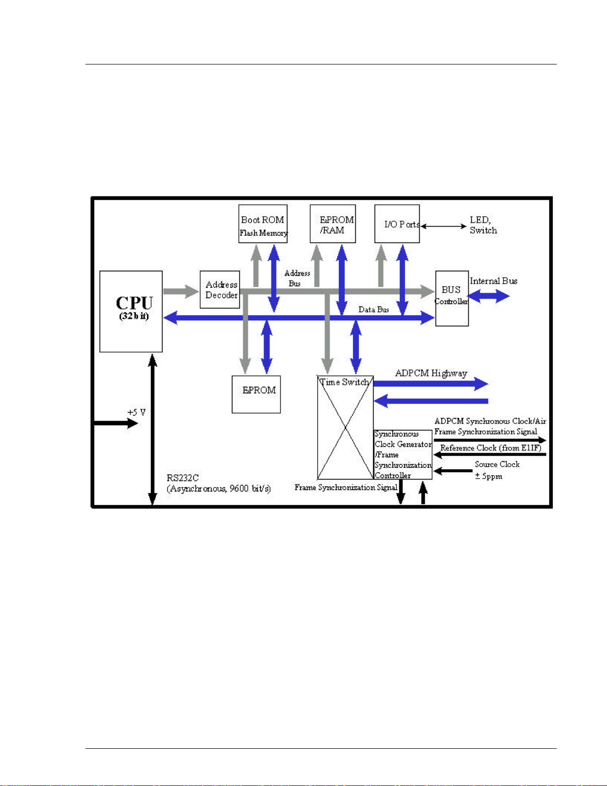
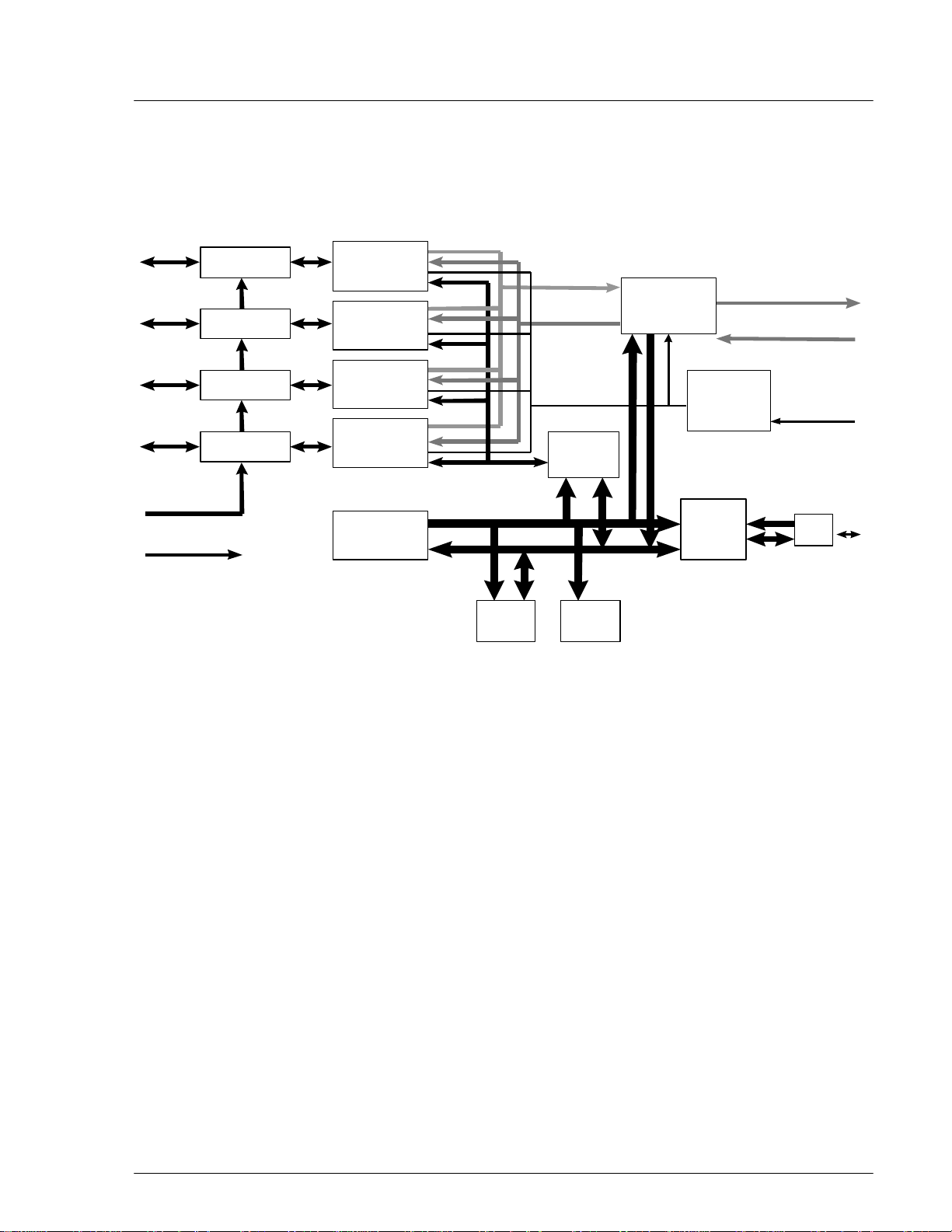
2.1.2.1 Enhanced Control Module
The ECNT module provides the Operation, Administration and Maintenance
(OA&M) support for the RPC. In addition, it provides the time slot cross connect
switch for communications between the E1IFs and the RPIFs. Figure 2-3
represents the ECNT functions.
Figure 2-3: ECNT Block Diagram
The ECNT module performs the clock synchronization by generating a
synchronized clock from the extracted clock signal from the E1 line on the E1
interface card and delivers it to the RP lines on the RP interface cards.
The RPC uses a control bus via the ADPCM highway on the mother board to
synchronize the system. The Control Bus is an 8-bit mixed bus address with data
and First-in First-out (FIFO) type bus. The main CPU on the ECNT card, the
local CPUs on E1 Interface cards and the RP-interface cards are all connected by
this bus. The main CPU on the ECNT card controls the bus.
WLL-RPC/RP-IN/UM-1.0 19June2000
Page 18
RPC/RP Manual RPC Installation
5
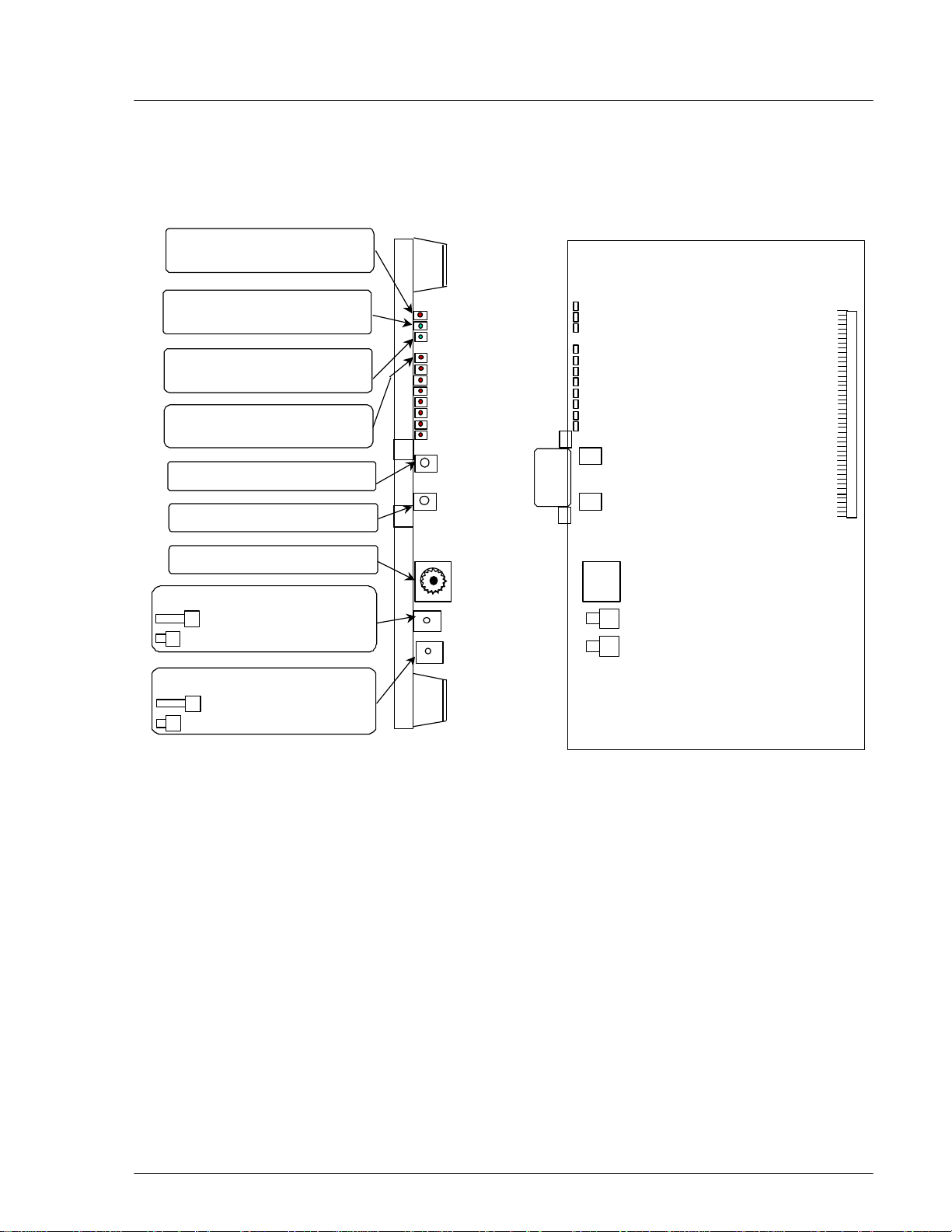
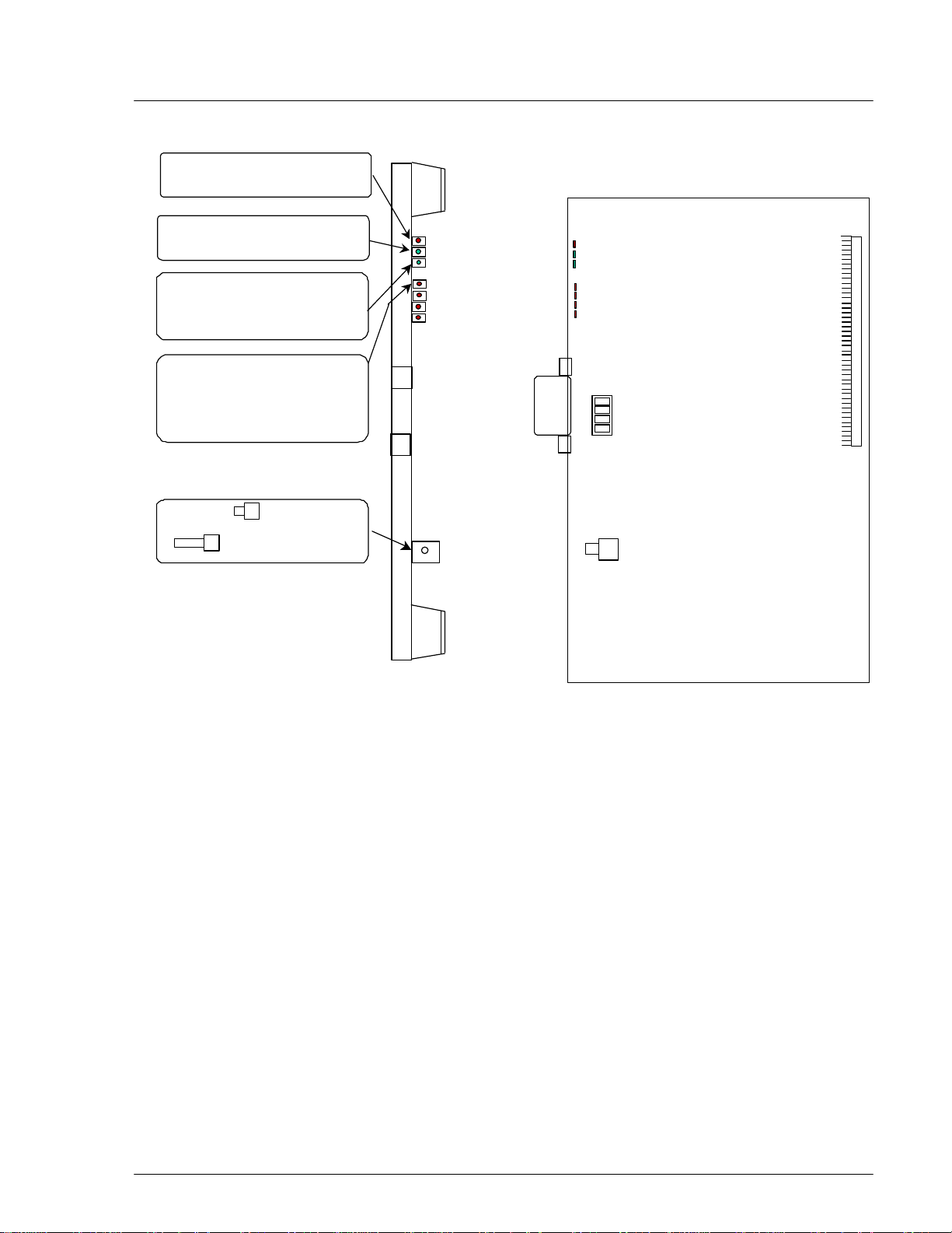
Figure 2-4 shows the module’s physical configuration and describes the function
of the LEDs and the reset switch.
ALM : Red =fault detected on this
module
RUN : Green=normal operations
2-
SYNC : Green=E1 interface circuit
established Layers 1 and 3
LEDs 0 through 7 : Red=Frame
Rotary Switch (U) : Setting=0
Rotary Switch (L) : Setting=2
RMT or PC Connector
System Reset Switch :
=Normal operations
=Reset system
Alarm Reset Switch :
=Normal operations
=Reset alarms
Figure 2-4: ECNT Module Layout
7
6
5
4
3
2
1
0
2.1.2.2 E1 Interface Module
The RPC connects to the COT through a 2.048 Mbps E1 Interface that carries all
the control and voice channels, that is, PCM encoded voice or voice band data,
between the COT and the RPC. The E1 Interface (E1IF) module communicates
externally with the COT through 1 G.703 E1 interface and uses Q.931 non-facility
associated signaling protocol.
Transmission between the RPC and RP is based on a proprietary, echo-canceled
transmission standard, which is similar to the recognized G.961 ISDN standard.
The E1IF provides the speech coding conversion between A-law PCM from the
COT and Adaptive Differential Pulse Code Modulation (ADPCM), which is ITU-
19June2000 WLL-RPC/RP-IN/UM-1.0
Page 19
2-
6
RPC Installation RPC/RP Manual
Rec.726 compliant, from the RP. It supports 32 kbps channel signaling for
encoded voice and voice band data calls.
In addition, the E1IF communicates internally with the Radio Port Interface
(RPIF) module for interfacing RPs through the backplane busses and the switch in
the ECNT module.
The E1IF module is an E1 module (E1M) that provides 4 E1 connections to the
E1 network. The E1 module has the following functions:
• Originates/terminates 4 G.703/G.704 2.048 Mbps E1 interface
• Provides 75 ohm unbalanced interface
• Provides LEDs for module and port status and alarms
• Performs CRC-4 on the E1 line according to G.706
• Monitors performance of each E1 line
• Detects errors and alarms on the E1 lines.
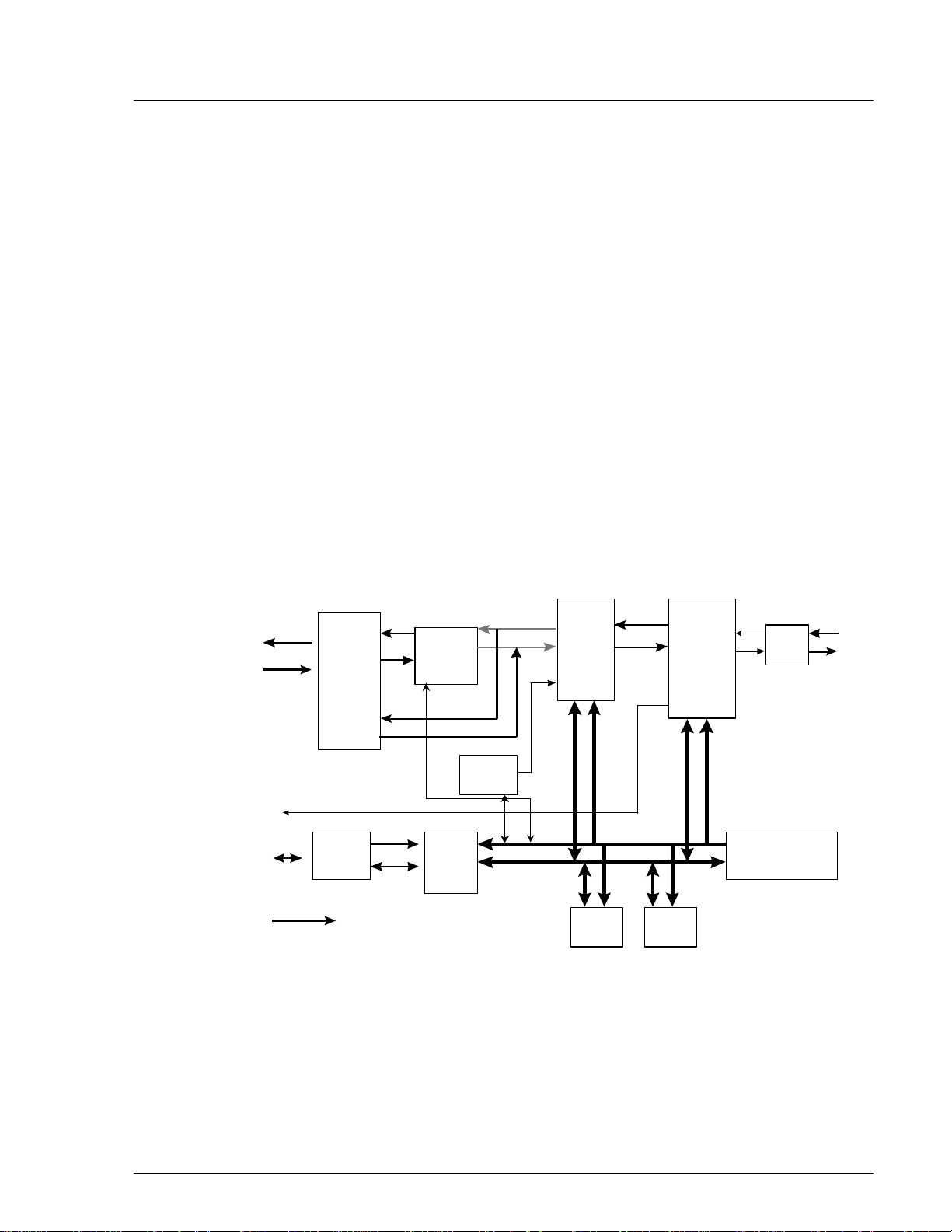
Figure 2-5 depicts the processing of the E1IF module
ADPCM
Highway
Internal
Bus
Highway
Exchanger
Reference
Clock
Bus
Controller
+5 V
A-law PCM Highway
ADPCM
CODEC
DTMF
Sender
DPRAM
Loudness
Controller
Address Bus
RAM ROM
Figure 2-5: E1 Interface (E1IF) Module Block Diagram
A-law PCM
Highway
Data Bus
E1 IF
LSI
E1 to
COT
LIF
CPU
(16 bit)
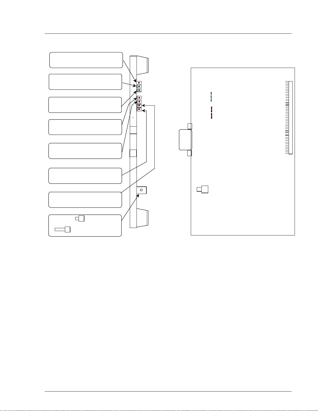
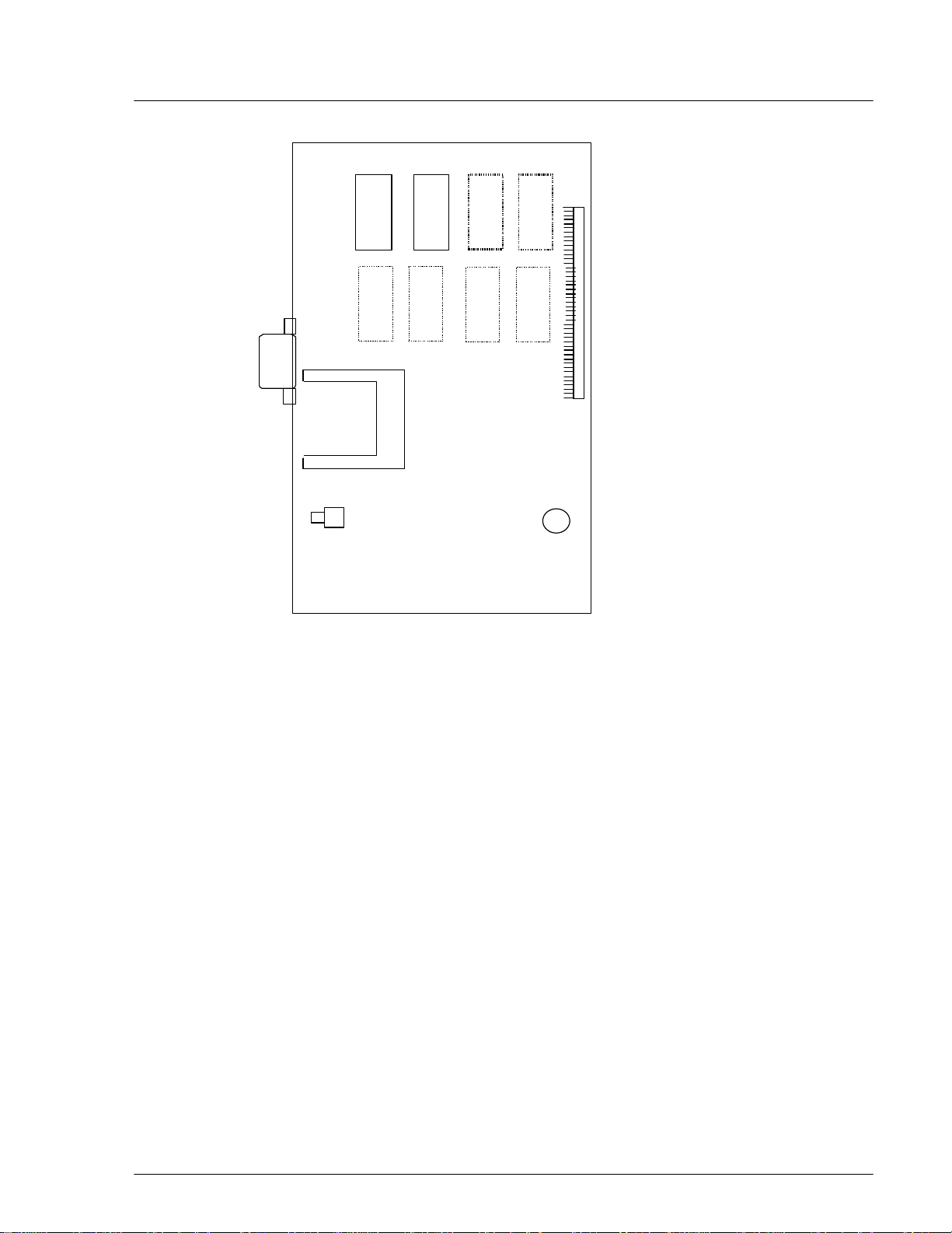
Figure 2-6 shows the module’s physical configuration and describes the function
of the LEDs and the reset switch.
WLL-RPC/RP-IN/UM-1.0 19June2000
Page 20
RPC/RP Manual RPC Installation
7
ALM : Red =fault detected on this
module
RUN : Green=normal operations
CHM : Green=E1 interface circuit
has established Layers 1 and 3
FSYC : Red=Frame out of
synchronization is dectected
LOS : Red=loss of signal is
dectected
AIS : Red=Alarm indication signal
is detected
2-
RAI : Red=RAI signal is detected
RST Switch :
=Resets the entire
interface module
= Normal operations
Figure 2-6: E1IF Module Layout
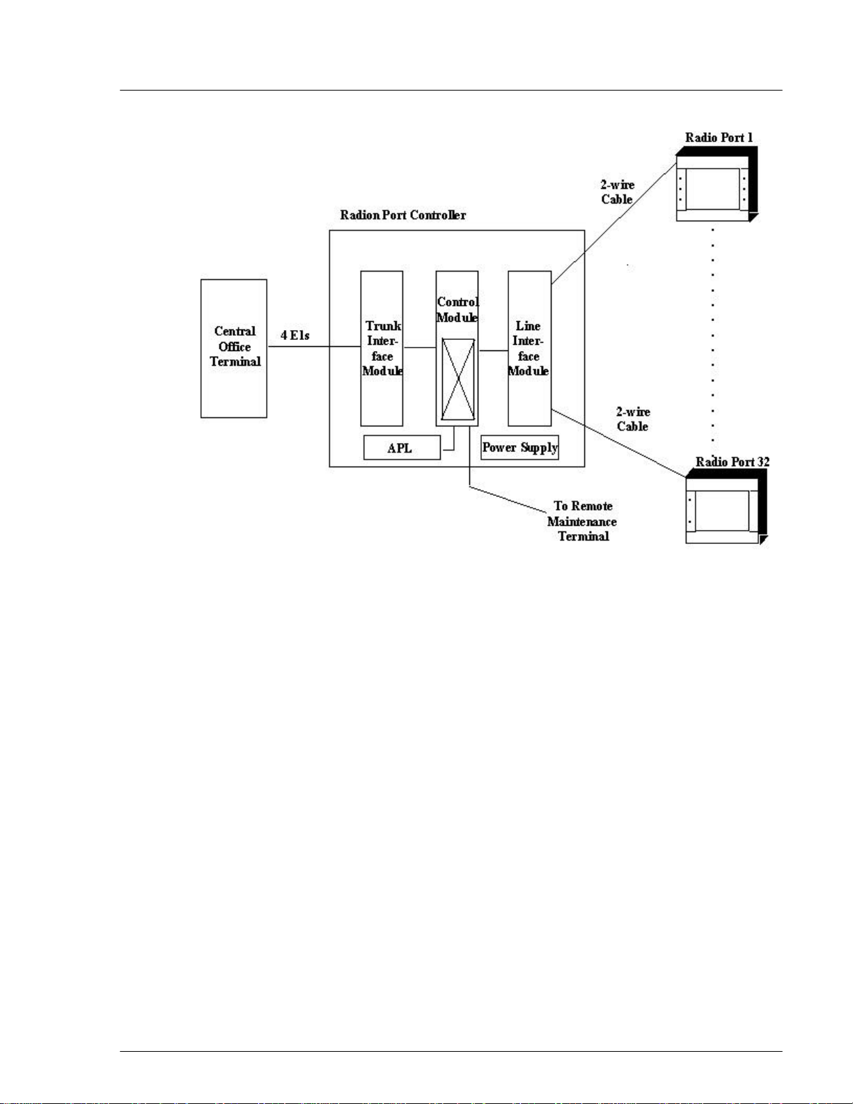
2.1.2.3 Radio Port Interface Module
Each RPC controls and feeds a maximum of 32 RPs. The RPC connects to the
RPs through a 2-wire proprietary interface. Line power feeding from the RPC
provides a power source of 116V DC to the RPs.
The RPC controls the RPs via 8 RPIF modules. Each RPIF module provides an
ISDN Basic Rate interface to 4 RPs. The RP is extended from the RPC to a
maximum distance of 5.0km using a pair of φ0.5 wires and approximately 3.5 km
using a pair of φ0.4 wires.
The Radio Port Interface (RPIF) module communicates externally with four RPs
through ISDN Basic Rate Interfaces (BRI). In addition, it communicates
19June2000 WLL-RPC/RP-IN/UM-1.0
Page 21
2-
8
Bus
Controller
RAM
ROM
Address Bus
Data Bus
ADPCM Highway
PCM
Clock/ Frame
signal
Generator
Internal
BUS
RPC Installation RPC/RP Manual
internally with the E1IF through the backplane busses and the switch in the ECNT
module. Refer to Figure 2-7 for a block diagram of the RPIF module’s
processing.
-116V
+5V
RPIF
RPIF
RPIF
Layer 1
Layer 1
Layer 1
LSI
LSI
LSI
Layer 1
RPIF
LSI
CPU
(16 bit)
Figure 2-7: RPIF Module Block Diagram
HDLC
Controller
Time slot
Assignment
Controller
DPRAM
ADPCM Highway
ADPCM Clock
Figure 2-8 shows the module’s physical configuration and describes the function
of the LEDs and the reset switch.
WLL-RPC/RP-IN/UM-1.0 19June2000
Page 22
RPC/RP Manual RPC Installation
9
ALM : Red =fault detected on this
module
RUN : Green=normal operations
SUS: Green=one or more Rps
operational
Not Lit=operations suspended
on all connected RPs
2-
RP1 through RP4 :
Green=normal operations
Red=RP not connected, is faulty or
is blocked
RST Switch :
=Resets the entire
interface module
= Normal operations
Figure 2-8: RPIF Module Layout
2.1.2.4 Application Software Loading Module
Distance
Switch
Short
Long
The Application Software Loading (APL) Module facilitates the downloading of
software in the event there is a problem in loading software. It permits the
upgrading of the ECNT module firmware. In addition, any software upgrades can
be downloaded remotely from a PC to an RPC. The APL module is installed only
when the software or firmware needs to be upgraded or downloaded. It is not
intended to remain in the system during the normal operations.
Figure 2-9 demonstrates the module’s physical configuration:
19June2000 WLL-RPC/RP-IN/UM-1.0
Page 23
2-
10
RPC Installation RPC/RP Manual
Figure 2-9: Application Module Layout
2.1.2.5 ADPCM Highway
The ADPCM (Adaptive Differential Pulse Code Modulation) highway is the
synchronous time multiplex digital voice/data path, and consists of up-stream and
down-stream for Time Switch on the ECNT card. Time Switch and the digital
voice and data paths on the E1IF cards and the RPIF cards are connected by the
ADPCM highway.
There are 8 ADPCM highways in an RPC. Half of them are assigned for E1IF
cards, and the rest are assigned for RPIF cards. The bit rate of an ADPCM
highway is 2048 kbps, and the frame repetition rate is 8 kHz.
2.2 System Construction
An RPC has two types of installation scenarios:
• Rack mount
• Stand-alone
WLL-RPC/RP-IN/UM-1.0 19June2000
Page 24
RPC/RP Manual RPC Installation
11
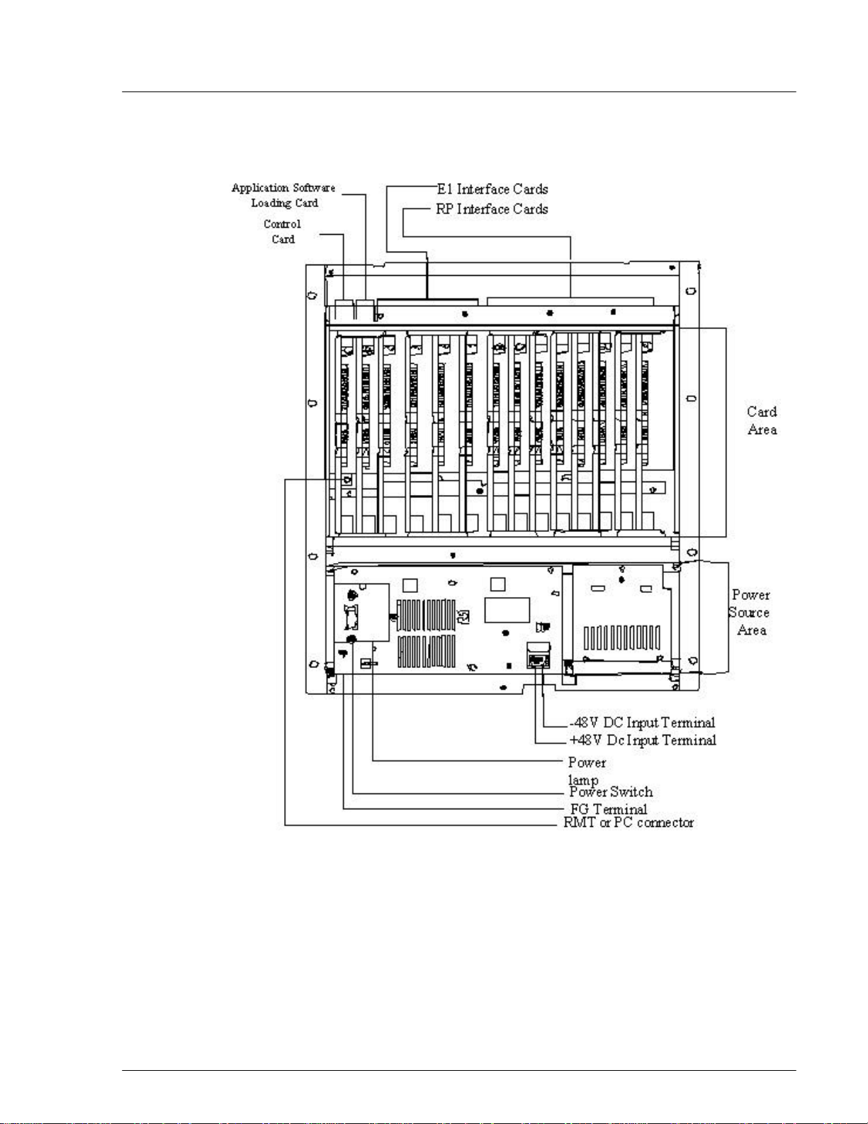
Figure 2-10 shows the physical configuration of the rack mount type RPC.
2-
Figure 2-10: Layout of Rack Mount Type RPC
The RPC is 532.6mm high, 482.6mm wide, and 265mm deep.
19June2000 WLL-RPC/RP-IN/UM-1.0
Page 25

2-
12
RPC Installation RPC/RP Manual
2.3 Installation
This section provides the instructions for installing an RPC. The flow chart in
Figure 2-11 depicts the steps involved in the installation.
Figure 2-11: RPC Installation Flow Chart
2.3.1 Before Beginning
To ensure that the RPC installation goes smoothly, it is necessary to do adequate
planning prior to the installation, including:
• Location of the RPC
• Tools required
• Number of people needed to complete an installation.
2.3.2 RPC Site Selection
The RPC needs an environment that is relatively dust and moisture free. Make
sure the location meets the following requirements:
WLL-RPC/RP-IN/UM-1.0 19June2000
Page 26

RPC/RP Manual RPC Installation
13
• Not in direct sunlight
• Free from extremes of heat, cold, and moisture
• 0° to 40° C ambient temperature
2.3.3 Tools Required
Be sure to have the following necessary tools:
• Screwdrivers
• Soldering iron and solder
• Tie bands for cabling
2.3.4 Installation Instructions
Follow the steps below to install the RPC:
1. Carefully unpack the RPC and the accessories and make sure that they are in
good condition. Accessories include 2 connectors for the RP connection
cables. Refer to Figure 2-12 for unpacking.
2-
19June2000 WLL-RPC/RP-IN/UM-1.0
Page 27

2-
14
RPC Installation RPC/RP Manual
Figure 2-12: Unpacking the RPC and Accessories
2. Before installing the RPC in the rack, make sure to remove the card cover and
the power source cover.
F CAUTION: Do not take a photo with a flash once the card cover has been
removed. RPC may not operate.
3. Loosen the thumbscrews. Tilt open the cover and slide it out as shown in
Figure 2-13.
WLL-RPC/RP-IN/UM-1.0 19June2000
Page 28

RPC/RP Manual RPC Installation
15
F CAUTION: The card cover cannot hold itself when opened. Be sure to detach it
from the cabinet.
2-
Figure 2-13: Removal of the Card Cover
4. Remove the 5 M3 screws in the power source cover and remove it, as
illustrated in Figure 2-14.
19June2000 WLL-RPC/RP-IN/UM-1.0
Page 29

2-
16
RPC Installation RPC/RP Manual
Figure 2-14: Removal of the Power Source Cover
F CAUTION: When inserting and removing each component, make sure to follow
the proper electro-static discharge (ESD) procedures.
5. Connect and wire the power source and FG cables, as shown in the figure
below.
WLL-RPC/RP-IN/UM-1.0 19June2000
Page 30

RPC/RP Manual RPC Installation
17
2-
Figure 2-15: Power and FG Cable Connectors
6. Insert the RPC in the rack and fasten to the rack with 8 screws as indicated in
Figure 2-16.
F CAUTION: Make sure the RPC is firmly mounted in the rack. Serious injury
could occur if the RPC fell out of the rack.
19June2000 WLL-RPC/RP-IN/UM-1.0
Page 31

2-
18
RPC Installation RPC/RP Manual
Figure 2-16: Mounting the RPC in the Rack
7. After installing the RPC in the rack, affix the wiring as indication in Figure
2-17. Redirect the support according to the direction of the wiring, as shown
in Figure 2-17.
WLL-RPC/RP-IN/UM-1.0 19June2000
Page 32

RPC/RP Manual RPC Installation
19
2-
Figure 2-17: Wiring – Back of RPC
8. Connect the coaxial cable with an SMB coaxial cable plug having an
impedance of 75 ohms into the E1IF connectors on the back of the RPC, as
shown in Figure 2-17
9. Connect the cable with a Champ plug to the RPIF connector on the back of
the RPC. Refer to Figure 2-17. Table 2-1 provides the maximum cable
lengths between the RPC and the RP for 2 different wire gauges. Refer to
Appendix A for the description of the 2 Champ RPIF connector pin
assignments.
19June2000 WLL-RPC/RP-IN/UM-1.0
Page 33

2-
20
RPC Installation RPC/RP Manual
Wire Guage Maximum Cable Length
φ0.4 m 3.5Km
φ0.5 m 5.0Km
Table 2-1: Maximum RP Cable Length
F NOTE: Be sure to use a twisted pair cable or a 2 pair twisted cable. Avoid any 2
pair twisted cable splits before connecting cables.
10. When the RP and E1 cables are connected, attach the cabling to the supports
with tie bands. Refer to Figure 2-18.
F NOTE: Tie Bands are to be prepared on-site.
Figure 2-18: Cabling Example
WLL-RPC/RP-IN/UM-1.0 19June2000
Page 34

RPC/RP Manual RPC Installation
21
11. Install the modules in the RPC slots according to the labels on the cabinet.
Refer to Figure 2-19 for the slot assignment.
F NOTE: The APL module is installed only when the software upgrades are
unsuccessful without it. It is not intended to remain in the system during normal
operations.
2-
Figure 2-19: RPC Slot Assignment
12. Make sure that the rotary switches on the ECNT module are correctly set
before applying power. The correct switch settings are shown in Table 2-2.
19June2000 WLL-RPC/RP-IN/UM-1.0
Page 35

2-
22
RPC Installation RPC/RP Manual
Switch Name Setting
Rotary Switch (U):S4 0
Rotary Switch (L):S5 2
Table 2-2: Rotary Switch Settings
13. Slide the card into the RPC shelf using the upper and lower slot guides. When
properly seated, the lower edge of the card is recessed from the outer edge of
the lower slot guide. And the upper edge of the card is flush with the outer
edge of the upper card guide. Refer to Figure 2-20.
WLL-RPC/RP-IN/UM-1.0 19June2000
Page 36

RPC/RP Manual RPC Installation
23
2-
Figure 2-20: Card Installation
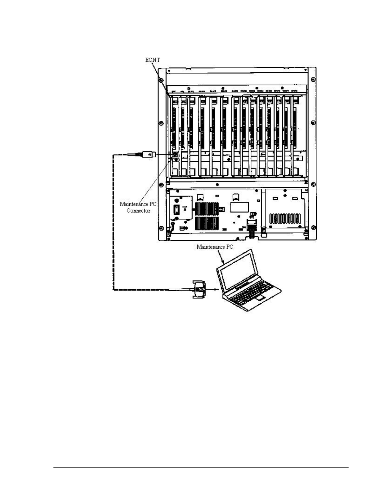
14. Connect the RMT or PC to the connector on the ECNT module. See Figure
2-21.
19June2000 WLL-RPC/RP-IN/UM-1.0
Page 37
2-
24
RPC Installation RPC/RP Manual
Figure 2-21: Maintenance Terminal or PC Connection
F NOTE: RPC maintenance and configuration can also be made throught the
network management system via the COT which is connected to the RPC.
15. Load operation data.
16. Replace the power source cover on the front of the RPC and secure it with
screws as shown in Figure 2-22.
WLL-RPC/RP-IN/UM-1.0 19June2000
Page 38

RPC/RP Manual RPC Installation
25
2-
Figure 2-22: Replacement of Power Source Cover
17. Replace the card cover. Make certain the hinge pins are properly aligned with
the hinge. Tighten the thumbscrews.
19June2000 WLL-RPC/RP-IN/UM-1.0
Page 39

2-
26
RPC Installation RPC/RP Manual
Figure 2-23: Replacement of the Card Cover
18. This concludes the RPC installation.
19. When the RPs have been installed and connected to the RP Interface cards,
measure the loop resistance of the cable. Then set the Distance Switch on the
RP Interface card based on the loop resistance value. Refer to the table and
figure below. The factory setting is Short.
Setting Loop Resistance
Long 150Ω or more
Short Less than 150Ω
Table 2-3: Distance Switch Settings
WLL-RPC/RP-IN/UM-1.0 19June2000
Page 40

RPC/RP Manual RPC Installation
27
2-
Figure 2-24: Distance Switch
19June2000 WLL-RPC/RP-IN/UM-1.0
Page 41

WLL-RPC/RP-IN/UM-1.0 19June2000
2-
28
RPC Installation RPC/RP Manual
Page 42

RP Installation
3 RP Installation
3.1 General Description
The Radio Port (RP) is the radio equipment base station that relays the
communication from the user side to the operator/network side or vice versa. A
standard installation for RP applications places several RPs in a common service
area. However, the number of RPs and their distribution deployment depend on
the following factors:
3
• Topography of the service area
• Subscriber distribution in the service area
• Desired Grade of Service and traffic load.
There are two types of RPs:
• Outdoor - is small in size and is encased in a weather-proof cabinet. This
gives it the potential for various mounting scenarios - installed on the
dedicated poles, buildings, or street lamp poles.
• Indoor - is also small in size and can be installed in public and semi-public
locations like an office building, a shopping mall, or an underground
parking lot.
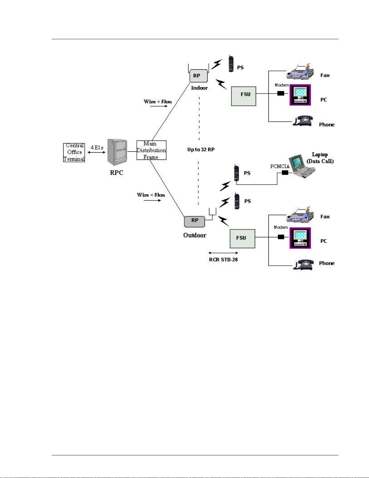
The power for the RP is fed from the RPC and a synchronous clock is delivered
from the RPC. The radio link between the RP and the FSU, or the RP and the PS
is based on RCR-STD 28 Ver.2 PHS technology, which defines frequency bands,
protocol, and so on. Both the indoor and the outdoor RPs have a 2 branch built-in
antenna.
The architecture of the WLL system is illustrated in Figure 3-1, which is followed
by a block diagram of the RP.
19June2000 WLL-RPC/RP-IN/UM-1.0
Page 43

3-
2
RP Installation RPC/RP Manual
Figure 3-1: RP in the WLL System
WLL-RPC/RP-IN/UM-1.0 19June2000
Page 44

RPC/RP Manual RP Installation
3
Figure 3-2: Radio Port Block Diagram
3-
3.1.1 Traffic Handling
PHS applies Time Division Multiplex Access (TDMA) and Time Division
Duplex (TDD) techniques. Each individual radio link between the RP and the
FSU/PS is assigned 1 time slot for a control channel (C-ch) and 3 slots for traffic
channels (T-chs).
In the case of a single RP, there are 4 time slots installed for radio links. One slot
is the control channel for signaling and the other three are the traffic channels.
The number of accommodated subscribers in that RP covering the zone calculated
according to the erlang theory is as follows:
• Erlang per zone (3 T-chs, GOS=5%) = 0.899 erlang
• Subscribers (FSUs or PSs) (0.899÷.08) = 11 subscribers
Group Control maximizes the number of channels available for traffic by
allowing one control channel to control up to 8 RPs (up to 31 traffic channels),
which is an efficient application for high traffic areas. One master RP can control
a maximum of 7 RPs in the same area. The master RP has one control channel,
and all the other channels are assigned for traffic, leaving 31 channels open for
traffic. Figure 3-3 represents the group control configuration with 4 RPs in the
group.
19June2000 WLL-RPC/RP-IN/UM-1.0
Page 45

3-
4
RP Installation RPC/RP Manual
Figure 3-3: Group Control RPs
In the group control mode, the number of accommodated subscribers in the group
control coverage zone is calculated in accordance with the erlang theory as
follows (with 4 RPs in the group):
• Erlang per zone (15 T-chs, GOS=5%) = 10.663 erlang
• Subscribers (FSUs or PSs) (10.663÷.08) = 132 subscribers
The comparison for the number of accommodated subscribers between the group
controlled RPs and the single RP is shown in Figure 3-4.
F NOTE: Figure 3-4 represents the group control with 4 RPs. Each group can
have a maximum of 8 RPs.
WLL-RPC/RP-IN/UM-1.0 19June2000
Page 46

RPC/RP Manual RP Installation
5
3-
Figure 3-4: Accommodated Subscribers per RP in Group and Non-group Control
The recommended installation design for RPs is as follows:
• A zone of sparse subscribers should be covered by non-group controlled
RPs.
• A zone of dense subscribes should be covered by group-controlled RPs.
The number of accommodated subscribers is the greatest when all of the RPs
connected to an RPC are configured in the group control mode. In this case (with
4 RPs in each group), the number of service zones is eight (32÷4), and the
maximum number of subscribers is 1,056 (132x8). Each Group Control zone
supplies 15 traffic channels. Eight zones require 120 channels (15x8) provided by
4 E1 lines with 30 channels each.
3.1.2 Cell Overlap
Maximum service results are achieved when the RP coverage area is strategically
installed in a Cell Overlap Capacity.
19June2000 WLL-RPC/RP-IN/UM-1.0
Page 47

3-
6
RP Installation RPC/RP Manual
Figure 3-5: Coverage Service Area with Cell Overlap
The combination of Cell Overlap and Dynamic Channel Allocation increases the
flexibility and the capacity of the system. Every user has access to all channels
(77x4) due to the overlapping base station topology. Cell Overlap enhances the
reliability and service quality. One malfunctioning base station does not affect
the performance of the system. Due to the Dynamic Channel Allocation, there is
no need for frequency planning, which allows the network to meet operators
current demands with the option to easily expand at a later date.
3.1.3 Air Interface Handling
The radio interface has four-channel time division multiple access capability with time
division duplexing (4-channel TDMA-TDD), which provides one control channel and
three traffic channels for each cell station.
WLL-RPC/RP-IN/UM-1.0 19June2000
Page 48

RPC/RP Manual RP Installation
7
3-
Figure 3-6: Radio Channel Structure
The radio frequency allocation shown in Figure 3-6 displays a typical radio
channel structure when three cordless handsets are operating through a single RP.
RCR STD-28 does not designate a control channel prior to the operation. Instead,
it assigns the control slot to any one of the four available slots.
Traffic channels are not preassigned. Channel assignment is performed by a
distributed-autonomous dynamic channel assignment scheme and is an essential
function of the WLL radio system. Channel assignment for new communication
is selected from the available channel resources mapped in a two-dimensional
frequency-time matrix renewed by the result of checking signal strength when the
call is established. The RP also completes handling of the signaling process over
the radio segment.
Due to the separation of the traffic and control channels, traffic channels can be
allocated in a distributed and autonomous manner by employing the switching
TDMA mechanism. In order to maximize the benefit of carrier switching TDMA,
the RP uses a system that synchronizes radio frames by superimposing
synchronization data on the B interface. The result of this synchronization is an
improved utilization of frequency as compared to asynchronous systems.
In addition, with TDMA-TDD and the diversity of the RP transmission and
reception, it is not necessary to install the multiple antenna or receiver-branch
diversity mechanisms in the PS handsets to improve the data communication
19June2000 WLL-RPC/RP-IN/UM-1.0
Page 49

3-
8
RP Installation RPC/RP Manual
quality. TDMA enables the antennas to share both transmitting and receiving
with the RF switches. To implement receiving diversity, the receiving units have
two receiving branches, while the transmitting unit has switches for switching
antennas to provide the transmission diversity.
3.2 System Construction
Figure 3-7 represents the RPC and RP configuration.
WLL-RPC/RP-IN/UM-1.0 19June2000
Page 50

RPC/RP Manual RP Installation
9
3-
Figure 3-7: RPC and RP Configuration
The dimensions of the indoor Radio Port are as follows:
• Height:142 mm
19June2000 WLL-RPC/RP-IN/UM-1.0
Page 51

3-
10
RP Installation RPC/RP Manual
• Width:154 mm
• Depth:47 mm
The dimensions of the outdoor Radio Port are as follows:
• Height:214±2.5 mm
• Width:260±2.5 mm
3.3 Indoor RP Installation Instructions
This section provides the instructions for installing an indoor RP. The flow chart
in Figure 3-8 describes the steps involved in the installation.
Figure 3-8: Indoor RP Installation Flow Chart
3.3.1 Before Beginning
To ensure that the RP installation goes smoothly, it is necessary to do adequate
planning prior to the installation. Things to consider:
• Correct placement of the RP
• Tools required
• Number of people needed to complete the installation
WLL-RPC/RP-IN/UM-1.0 19June2000
Page 52

RPC/RP Manual RP Installation
11
3.3.2 Site Selection
For indoor RP installation, select a site that satisfies the following requirements:
• Less than 3 meters from the RP antenna
• Not in direct sunlight or near a heat source such as a radiator
• Free from excessive humidity; not more that 95% non-condensing
• Free from excesses of heat or cold, not lower than -10°C nor higher than
+50°C
F NOTE: If more than 3 meters , consult a qualified field engineer.
3.3.3 Indoor RP Installation
Follow the steps below to install an indoor RP:
1. Carefully unpack the indoor RP and make sure it is in good condition.
3-
2. Attach the mounting plate to a wall with 2 screws as shown in Figure 3-9.
Figure 3-9: Indoor RP Mounting Plate
19June2000 WLL-RPC/RP-IN/UM-1.0
Page 53
3-
12
RP Installation RPC/RP Manual
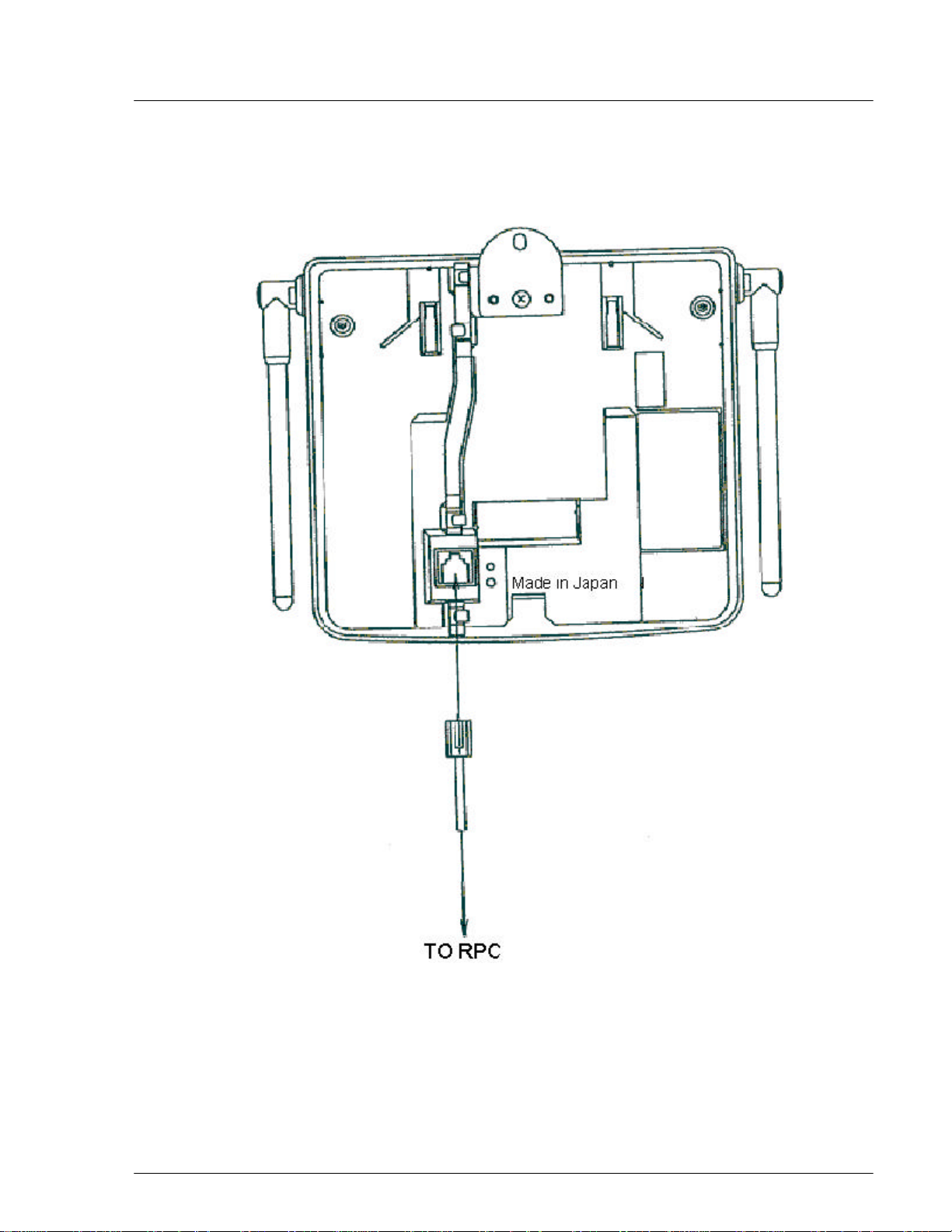
3. Insert the RJ-11 end of the RPC cable into the connector on the back of the
indoor RP. Refer to Figure 3-10.
Figure 3-10: Connection to RPC
4. Attach the indoor RP to the mounting plate with the special screw as indicated
in Figure 3-11.
WLL-RPC/RP-IN/UM-1.0 19June2000
Page 54

RPC/RP Manual RP Installation
13
3-
Figure 3-11: Indoor RP and Mounting Plate
5. This concludes the installation of the indoor RP.
3.4 Outdoor RP Installation Instructions
This section provides the instructions for installing the outdoor RP. The flow
chart in Figure 3-12 defines that steps involved in the installation.
19June2000 WLL-RPC/RP-IN/UM-1.0
Page 55

3-
14
RP Installation RPC/RP Manual
Figure 3-12: Outdoor RP Instruction Flow Chart
3.4.1 Before Beginning
To ensure that the outdoor RP installation goes smoothly, it is necessary to make
adequate planning prior to the installation, including:
• Tools required
• Number of people needed to complete the installation
• Location of the RP Main Unit
3.4.2 Outdoor RP Installation
Follow the steps below to install an outdoor RP:
1. Unpack the outdoor RP and accessories and make sure they are in good
condition. Refer to Figure 3-13. The package includes:
• Outdoor RP (1)
WLL-RPC/RP-IN/UM-1.0 19June2000
Page 56

RPC/RP Manual RP Installation
15
• Mounting plate (2)
• One M4 screw (3)
• Four M6 screws (4)
3-
Figure 3-13: Overview of the RP, Packing, and Accessories
2. Make sure that the outdoor RP is installed in one of the positions shown in
Figure 3-14.
19June2000 WLL-RPC/RP-IN/UM-1.0
Page 57

3-
16
RP Installation RPC/RP Manual
Figure 3-14: Outdoor RP Recommended Positions
F WARNING: Installation of the RP in any other position may permit moisture to
enter the device possibly causing damage or injury.
3. Pre-drill holes for bolts according to the dimensions shown in Figure 3-15.
Attach the mounting plate to a wall with 4 bolts. Notice that the lower right
edge of the mounting plate has a bend in it. The purpose of this bend is to
hold the antenna connectors in place. Refer to Figure 3-15.
WLL-RPC/RP-IN/UM-1.0 19June2000
Page 58

RPC/RP Manual RP Installation
17
3-
Figure 3-15: Mounting Plate
4. To remove the top cover, lower the screw caps and loosen the screws with the
special screwdriver. Pull the top cover backward and upward from the main
unit as shown in Figure 3-16.
19June2000 WLL-RPC/RP-IN/UM-1.0
Page 59

3-
18
RP Installation RPC/RP Manual
Figure 3-16: Top Cover Removal
WLL-RPC/RP-IN/UM-1.0 19June2000
Page 60

RPC/RP Manual RP Installation
19
5. Mount main unit on the mounting plate. Position both the hinge pins in the unotches on the mounting plate. Refer to Figure 3-17. Do not fasten with the
screws right now. The antenna cables must be connected first.
3-
Figure 3-17: Mount Main Unit
6. Connect each antenna cable and push the antenna connectors and surplus
antenna cable in between the mounting plate and the RP main unit. Make sure
that the antenna connectors are above the holding bend of the mounting plate
and that the antenna cables are not caught by it.
19June2000 WLL-RPC/RP-IN/UM-1.0
Page 61

3-
20
RP Installation RPC/RP Manual
Figure 3-18: Antenna Cable Connections
7. Affix main unit to the mounting plate with the M4 screw as shown in Figure
3-19.
WLL-RPC/RP-IN/UM-1.0 19June2000
Page 62

RPC/RP Manual RP Installation
21
3-
Figure 3-19: RP Attachment to the Mounting Plate
8. Replace the top cover. Make sure it is properly positioned over the fin on the
main unit as shown in Figure 3-20. Tighten the screws in the top cover and
replace the screw caps.
19June2000 WLL-RPC/RP-IN/UM-1.0
Page 63

3-
22
RP Installation RPC/RP Manual
Figure 3-20: Top Cover Attachment
9. This completes the installation of the outdoor RP.
WLL-RPC/RP-IN/UM-1.0 19June2000
Page 64

RPC/RP Manual RP Installation
19June2000 WLL-RPC/RP-IN/UM-1.0
23
3-
Page 65
RPC/RP
Configuration
4 RPC/RP Configuration
After the installation of the RPC and RP, configuration must be made to provision
the RPC and RP. This is done through the Netman network management system.
Netman is the network management tool for the system. It centralizes the
management of all the DMs in the network, including the RPCs. This chapter
describes the RPC/RP configuration process through Netman 2000.
4.1 Initialize an RPC Node
4
RPCs are represented as independent DMs on the Netman Main View window
although they are actually controlled by the COT node to which they are attached.
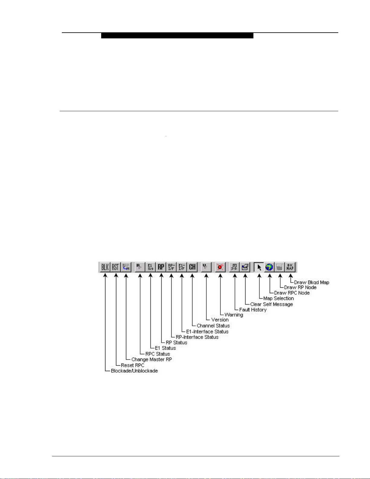
Figure 4-1 and Figure 4-2 represent the toolbar and pull-down menu of the RPC
DM window.
Figure 4-1: Toolbar and Description (RPC R2.4)
19June2000 WLL-RPC/RP-IN/UM-1.0
Page 66

RPC/RP Configuration RPC/RP Manual
2
4-
Figure 4-2: Netman Pull-down Menus (RPC R2.4)
This section describes the procedures to initialize an RPC node. Follow the steps
below to get connected to an RPC:
1. On the Main View window of the Netman network management system,
double click the target RPC icon. This opens the Connect RPCs window, as
shown below.
Figure 4-3: Connect RPCs Window
WLL-RPC/RP-IN/UM-1.0 19June2000
Page 67

RPC/RP Manual RPC/RP Configuration
3
2. There are 15 RPCs to select from. Click the check boxes of the RPCs to be
connected and then click OK.
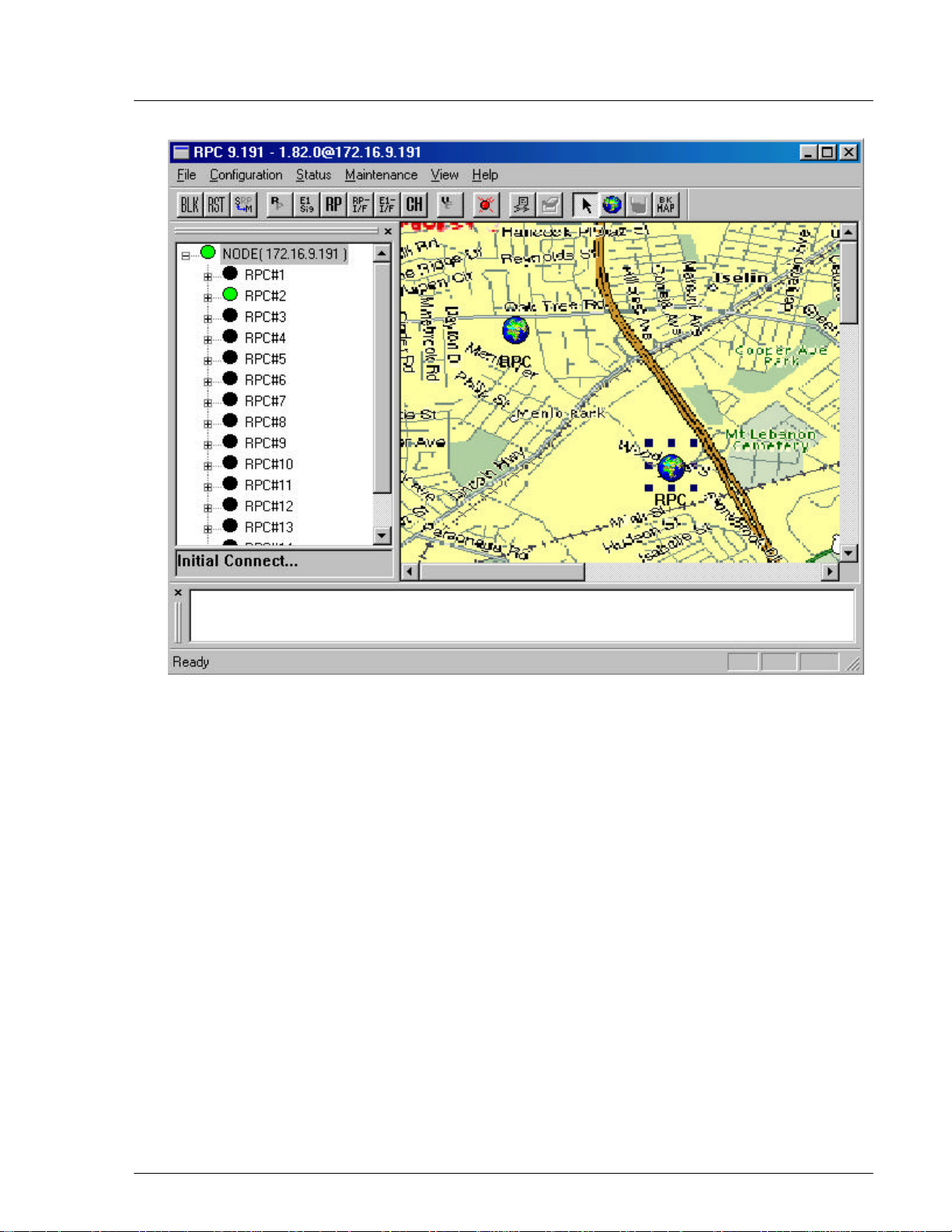
3. A connection status box appears, displaying the connection process. When
the process is complete, the RPC window opens with four frames, as
displayed in Figure 4-4.
4-
Figure 4-4: RPC Window
The top left frame is called the Unit View window. It lists the current units,
such as, RPCs, RPs, interfaces, etc. The NODE displays its IP address. The
connection status of the RPC nodes on the tree structure is represented in three
different colors. The green and red color indicate connected and unconnected
RPCs respectively, whereas the RPC nodes in black color indicate that they
are not selected for connection.
The top right frame is called the Status View window. It displays the relevant
status information corresponding to the selection on the left, on the menu bar,
or on the toolbar.
The small frame under the Unit View window is the Connection View
window. It displays the connection status and the connected RPC.
19June2000 WLL-RPC/RP-IN/UM-1.0
Page 68

RPC/RP Configuration RPC/RP Manual
4
4-
Finally, the frame at the bottom is the Self Messages window. It displays
messages about the command execution results, trap messages, or warnings, if
there is any.
4. To get connected to a certain RPC, reselect the RPC by clicking the RPC on
the Unit View window. A connection status box appears, displaying the
connection process. If the connection is successful, a message will appear on
the Connection View window, stating “Connected to RPC#…” If the
connection fails, the message will be: “Not Connected!”
5. When the connection is complete, the Status View window displays the
relevant status information about the RPC or other units under it, depending
on which unit is selected. The figure below illustrates an RPC window.
Figure 4-5: RPC Window
6. Open an RPC by clicking the + sign to the left of the RPC. This displays the
RPs, RP Interface Borad, E1 Signal, Node Interface Board, and Air Channel
inside. Users may access each of the RPs by clicking the + sign to the left of
the RPs. Each RPC controls 32 RPs.
WLL-RPC/RP-IN/UM-1.0 19June2000
Page 69

RPC/RP Manual RPC/RP Configuration
5
4.1.1 Background Map
A street map can be added as a background image on the Status View window to
highlight the location of the RPC or RP.
1. Click NODE on the Unit View window to enable the Draw Background Map
button on the RPC window.
2. Click the Draw Background Map button and click anywhere on the Status
View window. The Background Map window opens, as shown in Figure
4-6.
4-
Figure 4-6: Background Map Window
3. Select the target background file from the Bitmap field. The Preview field
displays the selected background image. If users are satisfied with the image,
click OK. The image is pasted to the background of the Status View window,
as illustrated in Figure 4-7.
19June2000 WLL-RPC/RP-IN/UM-1.0
Page 70

RPC/RP Configuration RPC/RP Manual
6
4-
Figure 4-7: RPC Window with Background Image
4. To select another background image other than those on the Bitmap field,
click the New button. The Open window appears, as illustrated in Figure 4-8.
WLL-RPC/RP-IN/UM-1.0 19June2000
Page 71

RPC/RP Manual RPC/RP Configuration
7
Figure 4-8: Open Window
4-
5. Select the target bitmap file and click Open. The selected image file is added
to the Bitmap list and displayed on the Preview field. Click OK to paste the
image to the background of the Status View window if users are satisfied
with the image. A similar window appears, as illustrated previously in Figure
4-7.
4.1.2 Add RPC Icons on the Map
RPC icons can be added to the background map to highlight the location
information of the RPCs. They can be added, deleted or moved. All map
information is stored in the database.
1. To add an RPC icon to the map click the Draw RPC Node button on the RPC
window and click again on the target location of the map. The Property
window opens as shown in Figure 4-9.
19June2000 WLL-RPC/RP-IN/UM-1.0
Page 72

RPC/RP Configuration RPC/RP Manual
8
4-
Figure 4-9: RPC Property Window
2. Users enter the caption name, select the desired RPC number, enter the
address for that RPC, and click Finish. The RPC icon appears on the map
and the data are stored in the database, as illustrated in the figure below.
WLL-RPC/RP-IN/UM-1.0 19June2000
Page 73
RPC/RP Manual RPC/RP Configuration
9
4-
Figure 4-10: RPC Window with RPC icons on the Map
3. The RPC icons can be moved, deleted, or moved to the front or back of the
background map. Their properties can also be modified. To perform these
operations right click the target RPC icon and select the relevant option from
the pop-up menu.
4.1.3 Add RP Icons
RP icons can be added to the map under the dominant RPC. Follow the steps
below to perform the operation.
1. Double click the target RPC to access the blank Status View window and to
enable the Draw RP Node button. Now users can add the same background
map to the window. Following the procedure in the previous section to add
the background map. To add the RP icons on the map, click the Draw RP
Node button and click again on the target location of the map. The RP
Property window opens as illustrated in Figure 4-11.
19June2000 WLL-RPC/RP-IN/UM-1.0
Page 74

RPC/RP Configuration RPC/RP Manual
10
4-
Figure 4-11: RP Property Window
2. This window is similar to that in Figure 4-9. Enter the relevant data into the
fields and click Finish. The RP icon appears on the map and the data are
stored in the database. Repeat this process to add as many RP icons as
needed. Figure 4-12 illustrates a map with three RP icons.
WLL-RPC/RP-IN/UM-1.0 19June2000
Page 75

RPC/RP Manual RPC/RP Configuration
11
4-
Figure 4-12: RP Map Window
3. To return to the RPC map, click Node on the Unit View window. To re-
access the RP map, double click the target RPC icon on the RPC map.
4. The RP icons can be moved, deleted, or moved to the front or back of the
background map. Their properties can also be modified. To perform these
operations right click the target RP icon and select the relevant option from
the pop-up menu.
4.2 RPC Configuration
This section describes the procedures of provisioning an RPC. Double click the
target RPC node on the Main View window to open the Connect RPCs window.
Select the target RPCs and click OK. This opens the RPC window, as illustrated
in Figure 4-13. With this window open we can perform various types of
configuration to the connected RPCs.
19June2000 WLL-RPC/RP-IN/UM-1.0
 Loading...