


Introduction to This Manual Fixed Subscriber Unit Installation Manual
1. Introduction to This Manual
This manual contains all the information necessary to install and maintain the
Fixed Subscriber Unit (FSU).
1.1 Organization
This manual is organized to assist the installer and technician in gaining an
understanding of the Fixed Subscriber Unit in terms of the system’s physical
characteristics, installation instructions, and maintenance methods. Listed
below are descriptions of each chapter in this manual :
Introduction - Describes the contents of this manual.
General Description - Provides a high level description of the Fixed
Subscriber Unit System.
System Construction - Provides a more detailed system description of physical
characteristics.
1-1
Installation Instructions - Details all the steps necessary to install the device.
Acronyms and Abbreviations List - Provides definitions for each abbreviation
and acronym used in this manual.
Appendix A : Specifications - Lists the specifications for the FSU.
Release 1.00 10/03/97
Airstar-Wireless Local Loop

1-2 Introduction to This Manual Fixed Subscriber Unit Installation Manual
10/03/97 Release 1.00
Airstar-Wireless Local Loop
Fixed Subscriber Unit Installation Manual General Description
2. General Description
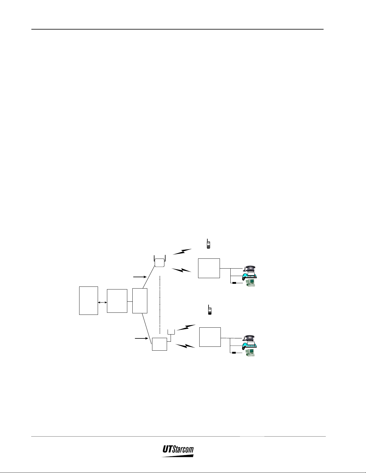
The Fixed Subscriber Unit (FSU) is the radio equipment that connects to fixed
standard telephones and is located in the subscriber’s residence. FSUs consist
of a Radio Frequency (RF) interface and a telephone line interface. Together
they manage the supplied line voltage, the ringing signal, Dial Tone (DT) and
Busy Tone (BT) to the telephone, detect off-hook and on-hook states, and
dialing.
In a zone near the Radio Port (RP), the FSU uses a 4.5 dBi, omni-directional,
attached antenna. In zones far from the RP, the FSU uses a 10 dBi,
directional, Yagi type, attached antenna. In mid-range zones, the FSU uses a 7
dBi omni-directional antenna. The telephone line interface consists of a
BRSH (Battery supply, Ringing Supervision, Hybrid) circuit, service tone
generator, DTMF receiver, and ADPCM CODEC.
The number of fixed standard connected telephones from the same battery
supply circuit is three. The power of FSU is fed from the external DC power
generated by AC adapter.
2-3
Figure 2-1 shows the FSU in the Airstar-WLL system architecture.
…..
…..
…..
Personal
Station
Fixed
Ssubscriber
Air Interface
RCR STD-28
Unit
…..
…..
…..
Personal
Station
Fixed
Ssubscriber
Unit
Modem
Modem
Central
Office
Terminal
4 E1s
Copper Pair
Up to 5Km
Radio
Port
Controller
Copper Pair
Up to 5Km
Indoor RP
Distribution
Main
Frame
Up to 32
Outdoor RP
Phone
FAX
Computer
Phone
FAX
Computer
Figure 2-1 : Overview of FSU in Airstar-WLL System
The following sections describe the air interface call handling procedures for
outgoing and incoming calls. In addition, brief descriptions of the
Release 1.00 10/03/97
Airstar-Wireless Local Loop
General Description Fixed Subscriber Unit Installation Manual
2-4
authentication, hooking signal transmission, and meter pulsing signal
transmission functions are provided.
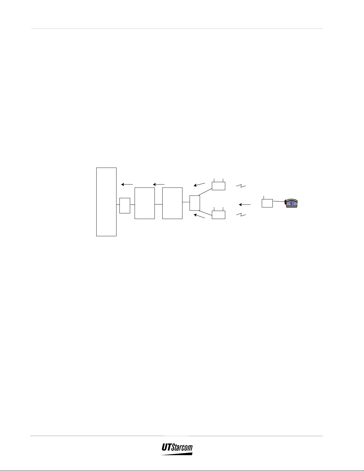
2.1 Outgoing calls
The call handling procedure for an outgoing call is depicted in Figure 2-2 and
is described following the figure. A terminal on an FSU sends dialing
information with standard in-band DTMF tones after recognizing dial tone.
5
CO COT
Switch
MDF
Figure 2-2 : Outgoing Call
1. When the fixed standard telephone connected to the FSU
4
3
RP
1
2
RPC
MDF
FSU
RP
3
goes off-hook, the FSU detects the off-hook state, seizes
the radio link to the RP, and generates a signal to the
standard telephone. If all radio channels are occupied, a
Busy Tone is heard. Otherwise the FSU stores the dial code
from the standard telephone, converts the outgoing message
with the telephone’s number of Personal Handyphone
System (PHS) protocol, and transmits the message to the
RP.
2. The RP receives the message from that FSU through the
radio link.
10/03/97 Release 1.00
Airstar-Wireless Local Loop
Fixed Subscriber Unit Installation Manual General Description
3. The RP resends the received message to the Radio Port
Controller (RPC) through the twisted pair wires via the
Main Distribution Frame (MDF).
4. The RPC converts the PHS protocol message to a Q.931
protocol message. In addition, the RPC extracts the dial
code from the outgoing message, and changes it to DTMF
signals. The Q.931 message is sent to the COT through the
D-channel of the E1 line.
5. When the COT receives the outgoing message, it converts
that message, selects and seizes the corresponding analog
line interface to the CO, and returns the seized message to
the RPC. The RPC sends the DTMF dialing signals to the
CO Switch through the voice path via the MDF. After
dialing, the RPC and RP connect all voice paths between
the CO Switch and the FSU connected to the outgoing
standard telephone. The destination telephone rings and is
picked up, and the outgoing call is put through. A voice
path is now established between the 2 telephones.
2-5
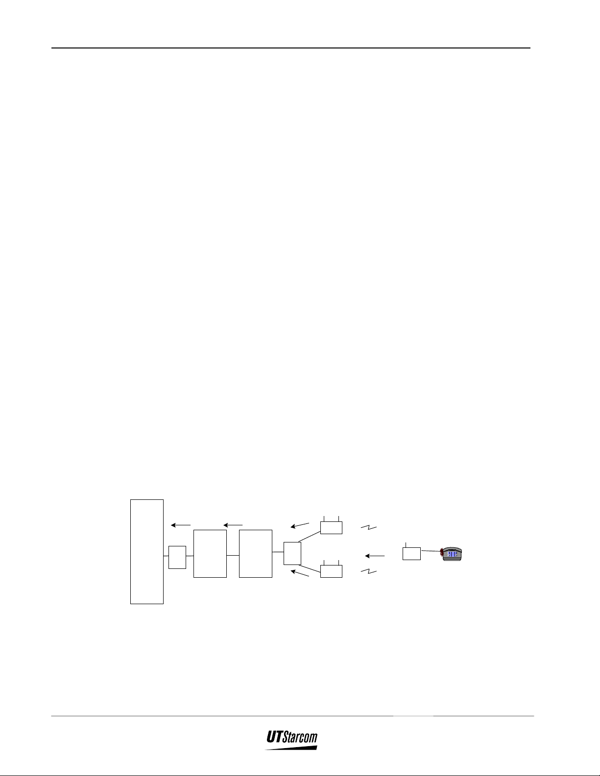
2.2 Incoming Call
The call handling procedure for an incoming call is depicted in Figure 2-3 and
is described following the figure.
1
CO COT
Switch
MDF
2
RPC
3
MDF
3
RP
RP
4
5
FSU
Figure 2-3 : Incoming Calls
Release 1.00 10/03/97
Airstar-Wireless Local Loop

General Description Fixed Subscriber Unit Installation Manual
2-6
1. A specific analog line is rung in the CO. The signal is sent
to the COT via the MDF.
2. The COT detects the ringing of the line and sends the
incoming message with the Q.931 calling number to the
RPC.
3. When the RPC receives the incoming message from the
COT, the RPC converts that Q.931 message to the PHS
incoming message protocol and sends it through the MDF
to all of the RPs.
4. The RPs page all FSUs and PSs. When the corresponding
FSU number receives the paging message from the RP, it
rings the connected telephone.
5. If the ringing telephone is lifted off-hook, an off-hook
message is sent to the CO switch through the RP, RPC and
COT. Speech paths are established between the connected
telephones.
NOTE : If a call is received while dialing out, the incoming call has priority. In the
case of overlap sending, only DTMF dialing is availaable and DP is not
supported.
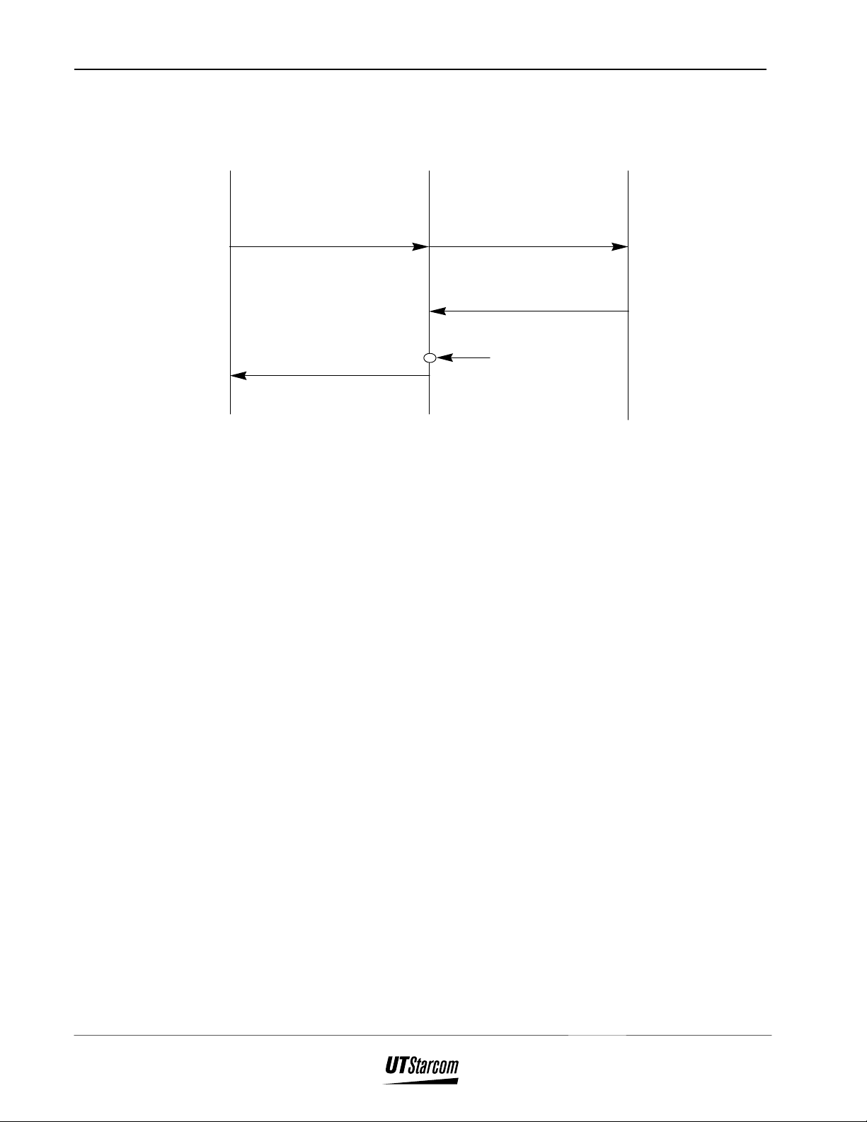
2.3 Authentication
Authentication is a function that prevents the unauthorized use of a
subscriber’s telephone number. The authentication procedure is performed
during Outgoing Calls, Incoming Calls and Location Registration. At
subscription time each FSU is configured with a unique authentication key and
telephone number. The COT is also configured with the telephone numbers
and authentication keys for all FSUs within its management database. After
receiving an authentication key code from the COT, the RPC:
1. Generates a random authentication pattern and sends it to
the FSU.
2. Receives the calculation result from the FSU.
3. Checks the result and sends both the calculation and check
result to the COT.
10/03/97 Release 1.00
Airstar-Wireless Local Loop
Fixed Subscriber Unit Installation Manual General Description
COT RPC FSU
Facility
(Authentication Required (Key)) Authentication Req
Authentication Req
2-7
Facility
(Authentication Result)
Figure 2-4 : Authentication
2.4 Hooking Signal Transmission
The hooking signal transmission function relays the hooking signal message
from an FSU to a COT. The COT generates a hooking signal according to the
message.
Authentication
operation
(calculation
and check)
Release 1.00 10/03/97
Airstar-Wireless Local Loop

System Construction Fixed Subscriber Unit Installation Manual
2-8
10/03/97 Release 1.00
Airstar-Wireless Local Loop
System Construction Fixed Subscriber Unit Installation Manual
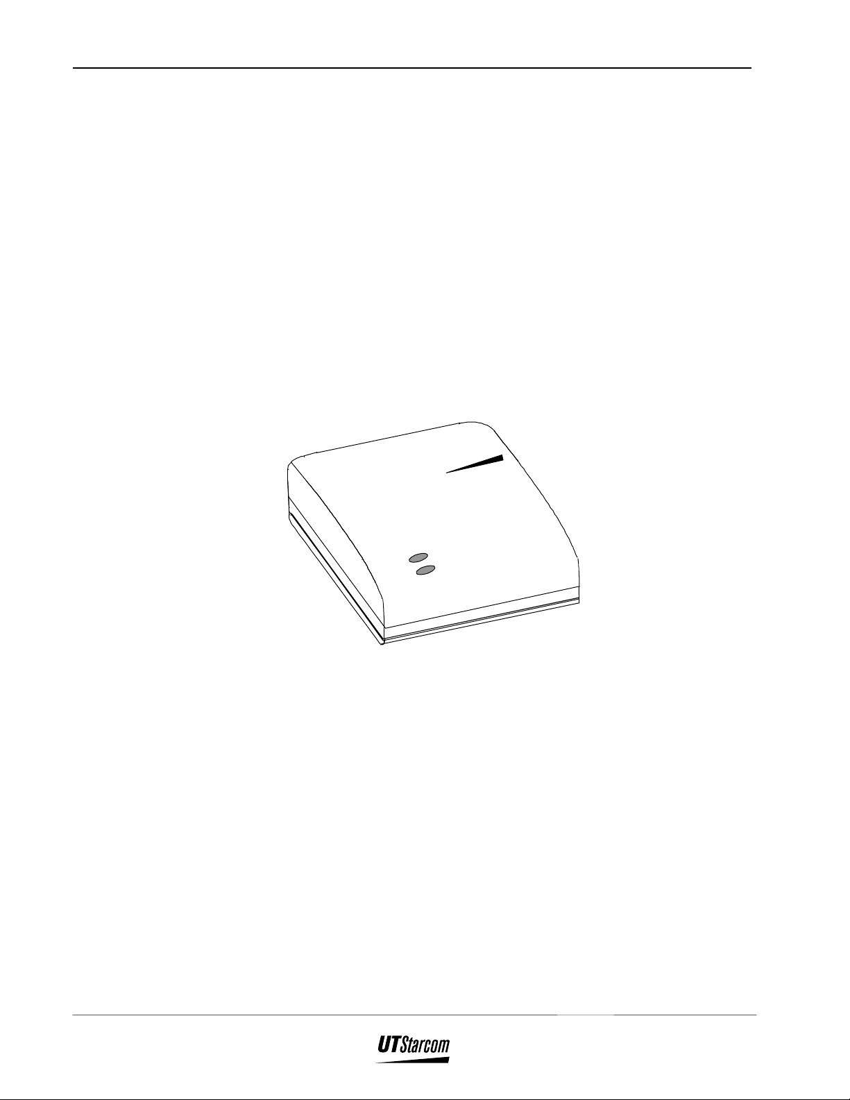
3. System Construction
The Fixed Subscriber Unit, as shown in Figure 3-1, has the following
dimensions:
• Length : 130mm
• Width : 175mm
• Depth : 40mm
Starcom
UT
3-9
MONITOR
POWER
Figure 3-1 : FSU - Main Unit
Refer to Appendix A for FSU specifications.
Release 1.00 10/03/97
Airstar-Wireless Local Loop

Installation Instructions Fixed Subscriber Unit Installation Manual
3-10
09/06/2001 Release 2.0
Airstar-Wireless Local Loop
Fixed Subscriber Unit Installation Manual Installation Instructions
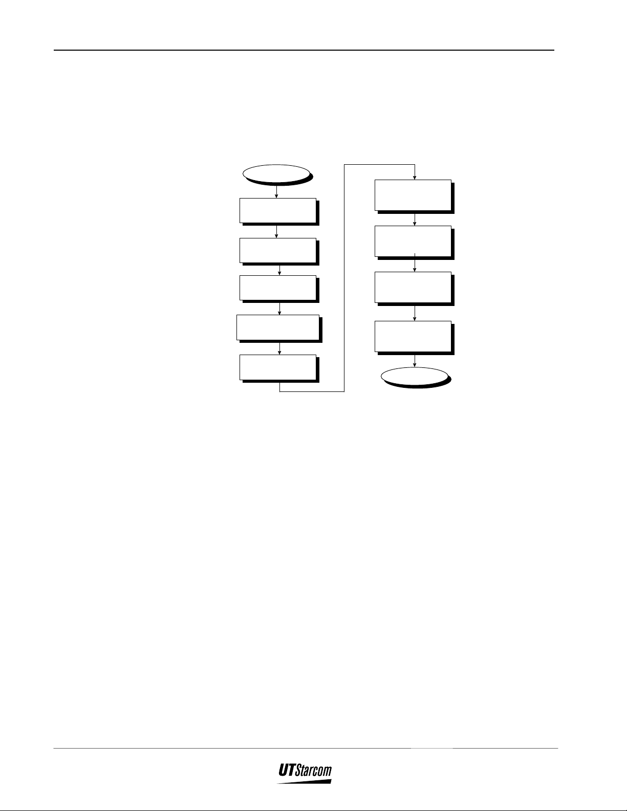
4. Installation Instructions
This section provides instructions for installing an FSU. The flow-chart in
Figure 4-1 defines the steps involved in an installation.
Begin
Install Antenna
Preparation
Install Coaxial
Choose Antenna
Location
Cable
4-11
Figure 4-1 : FSU Installation Flow Chart
4.1 Before Beginning
To ensure that the FSU installation goes smoothly, it is necessary to do
adequate planning prior to the installation. Things to consider:
Choose Main
Unit Location
Gather Accessories
and Tools
Configure
FSU
• Configuration of FSU
• Configuration of COT
Install Main Unit
Adjust Antenna
End
• Placement of the Main Unit and the Antenna
• Accessories, Standard and Special Tools required
• Number of people needed to complete an installation.
An FSU installation is accomplished in two parts : the Main Unit that is
installed indoors and the Antenna that is installed outdoors.
Release 1.00 10/03/97
Airstar-Wireless Local Loop

Installation Instructions Fixed Subscriber Unit Installation Manual
4-12
4.1.1 Plan FSU Configuration
The FSU must be configured at subscription time with the subscriber’s
telephone number, authentication key, operator ID, and carrier channel. The
subscriber’s data must also be entered into the COT. The following data must
be entered for each subscriber:
• Telephone number
• Authentication key
• FXO port
RP numbers of the RPs having the control channel for each FSU must also be
entered in the COT. The RP numbers are determined either by the Coverage
Map or by the installer at the subscriber’s site. Once the FSU main unit and
antenna are installed, the installer uses the PHS Field Analyzer or equivalent
to determine which RP’s signal is received by the FSU. This is accomplished
by measuring the Received Signal Strength (RSS). Some FSUs will receive
signals from multiple RPs, the installer must identify them and measure their
RSS. Once RP number(s) are configured in the COT for the FSU, these RPs
become the only RP(s) through which the FSU can place and receive calls.
Refer to Section 4.2 for additional information regarding FSU configuration
instructions.
Use local procedures to ensure that the COT’s System Administrator gets the
RP numbers and the associated telephone numbers for entry into the COT.
Until an FSU’s RP numbers are configured in the COT, it will use any
available RP for placing and receiving calls.
4.1.2 Antenna Orientation
Careful placement of the antenna is necessary to ensure clear reception.
Position the antenna so that it is :
• In clear view of a Radio Port
• Not blocked by buildings, summer foliage nor heavy traffic
of large vehicles
• At least 2 meters in height, use Coverage Map and on-site
measurements to determine exact height, usually 2 meters
or higher
• Directed towards the strongest RSS measurement, for
directional antenna only
09/06/2001 Release 2.0
Airstar-Wireless Local Loop

Fixed Subscriber Unit Installation Manual Installation Instructions
• On a wall or pole that is sufficiently strong, make sure wall
or pole can withstand winds common to the area
• Away from other objects such as poles, trees, buildings, and
so on that block the signal from the Radio Port; in general
the minimum distance is 750 mm.
4.1.3 Antenna Type Determination Guidelines
The Coverage Map shows Radio Port locations and the area covered by the
RP. The type of antenna installed depends on its distance from the Radio Port.
In general:
If distance is… Then use…
Less than 500m 4.5 dBi omni or directional antenna
Between 400m and 700m 7 dBi omni or directional antenna
4-13
Greater than 700m 10 dBi directional antenna
Table 4-1 : Antenna Type Determination Guidelines
There may be exceptions to the requirements in Table 4-1 identified by on-site
RSS measurements and/or by the specific radio environment.
4.1.4 Main Unit Site Selection
Choose a suitable location for the FSU Main Unit. Make sure the site will not
expose the device to :
• Direct sunlight
• Dampness or moisture
• Dust
• Magnetic fields
• Vibration
• Extremes of heat, cold or humidity.
Install the FSU on a stable surface, such as a desk or wall. Consider the length
of the AC Adapter cord in determining the Main Unit’s location. To avoid
possible interference from the connected telephone, make sure the Main Unit
is installed at least 1 meter away. To minimize the length of coaxial cable
Release 1.00 10/03/97
Airstar-Wireless Local Loop

Installation Instructions Fixed Subscriber Unit Installation Manual
4-14
between the main unit and the antenna, position the indoor main unit as close
as possible to the outdoor antenna.
Note : Make sure that the FSU Main Unit is positioned so that the green LEDs are
visible to the subscriber. When reporting trouble, the subscriber will be asked
the status of the LEDs.
4.1.5 Installation Accessories, Standard and Special Tools
This section lists all the equipment needed for and FSU installation. Be sure
to have all of these items on hand before beginning.
Accessories:
• Coaxial cable
• Coaxial cable connector (2 pieces)
• Marker
Note : In areas where lightning may strike, a lightning protector is required.
Standard Installation Tools:
• PVC tape
• Self-adhesive rubber tape
• Earth cable
• Solderless grounding terminal (optional)
• Bracket for cable
• U-bolt for pole mount
• Terminal lug
• Terminal lug crimper
• Wire cutter
• Adjustable wrench
• Pliers
• Cutter
• Flat screwdriver
09/06/2001 Release 2.0
Airstar-Wireless Local Loop

Fixed Subscriber Unit Installation Manual Installation Instructions
• Phillips (or Plus) screwdriver
• Electric drill
• Step ladder
• AC power extension cord
Special Tools for Cable Termination:
• Cable stripper
• Crimper
Antenna Orientation Instruments:
• Map
• Compass
• Binoculars
4-15
Measuring Receiver or Equivalent:
• Measuring receiver
• Memory card
• AC adapter
• Adapter (3-poles→2-poles conversion)
• Coaxial cable adapter TNC-J/SM-J (optional)
• 5 meters of coaxial cable (optional)
• Power cable
4.2 FSU Configuration Instructions
The FSU’s configuration data consists of dozens of parameters that are loaded
at the factory. When a subscriber requests service, four of these parameters
must be re-configured. Re-configuring the FSU entails writing the following
information to the FSU’s Electrically Erasable Programmable Read Only
Memory (E2PROM):
• PS-ID
• Telephone number [PS Number (1-11)]
Release 1.00 10/03/97
Airstar-Wireless Local Loop

Installation Instructions Fixed Subscriber Unit Installation Manual
4-16
• Authentication key
• Operator ID
• Control carrier
The above data is entered using the PSJ_Jr. device connected to a PC that has
been loaded with the FSUJ software.
Note : The FSUJ screens shown in this section are presented in inverse black and
white for clarity.
WARNING : MAKE SURE THAT THE FSU’S CONFIGURATION DATA IS
READ PRIOR TO WRITING THE NEW CONFIGURATION
DATA. IF THE DATA IS WRITTEN BEFORE IT IS READ,
ALL OF THE CONFIGURATION DATA ON THE CURRENT
SCREEN WILL BE ERASED.
BE SURE TO COPY THE STANDARD CONFIGURATION
DATA TO A FLOPPY DISK FROM ANY FSU. THIS BACK UP
FLOPPY CAN THEN BE USED TO RE-LOAD
CONFIGURATION DATA THAT ACCIDENTLY GETS
ERASED.
Use the following procedures to configure an FSU:
1. Connect the PSJ_Jr. device to the PC running the FSUJ
software. Attach the RS-232 connector to the COM1 port
on back of the PC.
2. Make sure that the FSU’s power cable is disconnected.
Then connect the FSU to be configured to the PSJ_Jr.
device. Raise the connector cover and attach the special
FSU connector to the the back of the FSU. Refer to Figure
4-11. Attach the other end of the cable to the connector on
the PSJ_Jr. device labeled PS.
3. To execute the FSUJ software, double click on the f.bat
icon.
4. Enter the password and the FSUJ Menu shown in Figure 42 displays.
09/06/2001 Release 2.0
Airstar-Wireless Local Loop

Fixed Subscriber Unit Installation Manual Installation Instructions
Figure 4-2 : FSUJ Menu
5. Use the ↓ key to move the cursor to the WLLSO Setup
option and press the Enter ↵ key. This displays a WLLSO
Setup screen similar to the one shown in Figure 4-3.
4-17
Figure 4-3 : WLLSO Setup Screen Without Configuration Data
6. To read the factory configured data, press the F2 key. On
the screen, this key is labeled E2read.
Release 1.00 10/03/97
Airstar-Wireless Local Loop

Installation Instructions Fixed Subscriber Unit Installation Manual
4-18
7. A confirmation box appears prompting execute to read to
E2PROM. OK (Y/N). Enter Y. The screen is populated
with the factory configured data. Refer to Figure 4-4.
Figure 4-4 : WLLSO Setup Screen With Configuration Data
Note : This application uses the letter A for zero. Zero is used for a delimiter.
8. Use the ↓ key to move the cursor to the PS-ID field, enter
the new PS-ID number to be assigned to this FSU by
striking over the old numbers.
CAUTION : THE PS-ID NUMBER MUST BE UNIQUE ACROSS ALL PSs
AND FSUs IN THE SYSTEM.
9. In a similar manner, enter the telephone number, the
authentication key, operator ID, and the control carrier to be
assigned to this FSU.
10. When the new configuration data is entered, press the F1
key. This key is labeled E2writ on the screen. A
confirmation box appears prompting execute to write to
E2PROM OK? (Y/N). Enter Y. The new configuration
data is written to the E2PROM within the FSU.
09/06/2001 Release 2.0
Airstar-Wireless Local Loop

Fixed Subscriber Unit Installation Manual Installation Instructions
4.3 Coaxial Cable Installation
Once the locations for the antenna and the main unit have been determined,
use the procedures in this section to install the cable.
1. Measure and cut a length of cable to fit between the main
unit and the antenna.
2. Run the cable between the main unit and the antenna.
3. Using the cable stripper, strip both ends of the coaxial
cable. Refer to the figure below for exact dimensions to
strip.
4-19
6mm
6mm
3mm
Figure 4-5 : Stripped Coaxial Cable
4. Carefully mount the coaxial cable terminals onto the cable
ends.
5. Affix the cable terminals using the crimper.
Release 1.00 10/03/97
Airstar-Wireless Local Loop

Installation Instructions Fixed Subscriber Unit Installation Manual
4-20
4.4 Antenna Installation
NOTE : The antenna shown in this manual is one of the three types of antennae used
in the Airstar-WLL system.
1. Unpack the FSU Antenna and accessories. Make sure all
parts are in good condition. The FSU Antenna and
accessories are shown in Figure 4-6.
(1) Antenna (1) Bracket
(2) Bolt (M6)
(2) Hexagon Nut
(2) Spring Washer
(4) Plain Washer
Figure 4-6 : FSU Antenna and Accessories
(2) Screws
(2) small Plain Washer
(2) small Spring Washer
09/06/2001 Release 2.0
Airstar-Wireless Local Loop

Fixed Subscriber Unit Installation Manual Installation Instructions
2. Assemble the FSU antenna by attaching the bracket to the
antenna according to Figure 4-7.
4-21
Figure 4-7 : Antenna Bracket Assembly
3. After installing the antenna, use the PHS Signal Analyzer to
check the receiving signal level. Measure the reception
level (RX LVL) at the TNC connector on the FSU. Target
values are as follows :
• RX LVL: more than -78dBm (35dBµV)
• Frame Error Rate: less than 2%
Release 1.00 10/03/97
Airstar-Wireless Local Loop

Installation Instructions Fixed Subscriber Unit Installation Manual
4-22
4. At the site selected for the FSU antenna, tentatively mount
the antenna and take several RSS measurements
approximately 15 cm from the antenna. Position the
antenna where it receives that strongest signal. Then mount
the antenna on a pole. Refer to the figure below for
assembly of the bracket onto the pole
Weep Hole
Figure 4-8 : Antenna Mounted On Pole
Note : Make sure that the weep hole is positioned at the lower edge of the antenna
bracket as shown in Figure 4-8.
5. After installing the antenna, use the PHS Signal Analyzer to
check the receiving signal level. Measure the reception
level (RX LVL) at the TNC connector on the FSU. Target
values are as follows :
• RX LVL: more than -78 dBm (35 dBµV)
• Frame Error Rate: less than 2%
09/06/2001 Release 2.0
Airstar-Wireless Local Loop

Fixed Subscriber Unit Installation Manual Installation Instructions
WARNING : DEPENDING ON LOCATION, IT MAY BE NECESSARY TO
GROUND THE ANTENNA TO PREVENT DAMAGE BY
LIGHTNING. REFER TO THE FIGURE BELOW FOR A
DIAGRAM OF THE EARTH CABLE CONNECTION.
4-23
Terminal Lug
AWG 12
copper wire
insulated
6 inches above ground
ground line
5 ft. by .5 inch
copper clad rod
Figure 4-9 : Earth Cable Connection
6. Attach a terminal lug to the lower bracket screw and tighten
screw.
7. Plug insulated copper wire into the terminal lug and use the
terminal lug crimper to affix the copper wire to the terminal
lug.
8. Attach the other end of the copper wire to a copper clad rod
as shown in the figure above.
Release 1.00 10/03/97
Airstar-Wireless Local Loop

Installation Instructions Fixed Subscriber Unit Installation Manual
4-24
9. Connect the coaxial cable to the antenna as shown in Figure
4-10.
Coaxial Cable
Figure 4-10 : Coaxial Cable Connection to Antenna
10. Wrap the cable connection first with the self-adhesive
4.5 Main Unit Installation
Follow the steps below to install the FSU Main Unit in the subscriber’s
residence.
1. Unpack the FSU and accessories. Make sure all parts are in
rubber tape. Stretch the tape until it is ½ its original width.
Then wrap the PVC tape around the rubber tape.
good condition. The accessories include :
• AC Cord
• AC/DC Adapter
• Backup Battery Unit
Figure 4-11 shows the FSU and its accessories.
09/06/2001 Release 2.0
Airstar-Wireless Local Loop

Fixed Subscriber Unit Installation Manual Installation Instructions
Main Unit
Connector Cover
4-25
Figure 4-11 : FSU and Accessories
Release 1.00 10/03/97
Airstar-Wireless Local Loop

Installation Instructions Fixed Subscriber Unit Installation Manual
4-26
2. Connect the external antenna cable to the Antenna Cable Outlet located on
the back of the FSU. Refer to Figure 4-12.
Connector Cover
Figure 4-12 : Antenna Cable Connection
09/06/2001 Release 2.0
Airstar-Wireless Local Loop

Fixed Subscriber Unit Installation Manual Installation Instructions
3. Connect the telephone set to the RJ-11 jack on the back of
the FSU using a standard telephone cord. See Figure 4-13.
4-27
Figure 4-13 : Telephone Cord Connection
Note : The telephone cord must have an RJ-11 type plug.
Release 1.00 10/03/97
Airstar-Wireless Local Loop

Installation Instructions Fixed Subscriber Unit Installation Manual
4-28
4. Connect the Backup Battery Unit to the DC Input
receptacle, also on the back of the FSU.
NOTE : A fully charged backup battery allows the FSU to continue operation if
power fails. The backup battery provides approximately two hours of
talking time and approximately 20 hours of standby time. Recharging may
take up to 30 hours. In the event of a prolonged power failure, remove the
battery to avoid over discharging as this may shorten the battery’s life.
Backup batteries must be replaced every 2 years. The batteries’ capacity
decreases to 60% after 2 years , at approx. 25°C
Figure 4-14 : Backup Battery Unit Connection
09/06/2001 Release 2.0
Airstar-Wireless Local Loop

Fixed Subscriber Unit Installation Manual Installation Instructions
5. Connect the AC/DC Adapter to the Backup Battery Unit, as
shown in the figure below.
4-29
Figure 4-15 : AC/DC Adapter Connection
Release 1.00 10/03/97
Airstar-Wireless Local Loop

Installation Instructions Fixed Subscriber Unit Installation Manual
4-30
6. Connect the AC/DC Adapter to an AC outlet. Refer to
Figure 4-16. The Monitor Lamp on the FSU should light,
indicating the line is ready for use. If the Monitor Lamp
blinks or does not light, adjust the antenna until the
Monitor Lamp remains lit. If the Monitor Lamp does not
light after antenna adjustment, contact a qualified service
technician.
Figure 4-16 : AC Outlet Connection
09/06/2001 Release 2.0
Airstar-Wireless Local Loop

Fixed Subscriber Unit Installation Manual Installation Instructions
7. If wall mounting is desired, locate a position on the wall for
the FSU. Mark the screws’ locations using the enclosed
mounting template. Mount the main unit on the wall using
the supplied two screws. Refer to Figure 4-17.
84 mm
4-31
Figure 4-17 : Wall Mounting
8. If wall mounting is not desired, be sure to affix the Antenna
Cable to a stable surface such as a wall, a floor, or a table to
insure that the FSU does not move by force of a loose
antenna cable.
4.6 Antenna Orientation Adjustment
If it is necessary to adjust the position of the antenna, follow the steps below
to orient the antenna for better reception :
1. Loosen the bolts fastening the antenna to the bracket.
2. Connect the PHS Signal Analyzer to the antenna. It may be
necessary to use the coaxial cable adapter (TNC-J/SMA-J).
3. Turn on the PHS Signal Analyzer’s power and turn the
antenna to the direction with the maximum RSS level.
4. Tighten the fastening bolts.
Release 1.00 10/03/97
Airstar-Wireless Local Loop

Installation Instructions Fixed Subscriber Unit Installation Manual
4-32
Figure 4-18 depicts an FSU configuration in a subscriber’s residence.
FSU
RF
Interface
Telephone
Interface
Battery
Line
AC
Adapter
Standard
Telephone
Connector
To AC Outlet
Figure 4-18 : Fixed Subscriber Unit Configuration
09/06/2001 Release 2.0
Airstar-Wireless Local Loop

Fixed Subscriber Unit Installation Manual Acronym and Abbreviation List
5. Acronym and Abbreviation List
5-33
AC
ADPCM
BRSH
BT
C-channel
CO
CODEC
COT
DC
D-channel
DT
DTMF
Alternating Current
Adaptive Differential Pulse Code Modulation
Battery supply, Ringing Supervision, Hybrid
Busy Tone
Control Channel
Central Office
COde/DECode
Central Office Terminal
Direct Current
Data channel
Dial Tone
Dual Tone Multi-Frequency
FSU
MDF
PHS
PS
RF
RP
RSS
RSSI
T-channel
WLL
Fixed Subscriber Unit
Main Distribution Channel
Personal Handyphone System
Personal Station
Radio Frequency
Radio Port
Received Signal Strength
Received Signal Strength Indicator
Traffic channel
Wireless Local Loop
Release 1.00 10/03/97
Airstar-Wireless Local Loop

Acronym and Abbreviation List Fixed Subscriber Unit Installation Manual
5-34
09/06/2001 Release 2.0
Airstar-Wireless Local Loop
 Loading...