

Page 1

Instruction Manual
Page 2

CONTENTS
WARNING! FCC RF EXPOSURE COMPLIANCE............. ................ ................ ................ .......... 1
1. BEFORE USING THIS PRODUCTS
1.1
EXPLANATION OF ALERT SYMBOLS USED IN THIS MANUAL
1.2
FOR SAFE OPERATION - IT IS IMPORTANT YOU READ THIS
!
Telephone handling instructions
FOR SAFE OPERATION
1.3
FOR SAFE OPERATION - IT IS IMPORTANT YOU READ THIS
!
AC Adapter handling instructions
FOR SAFE OPERATION
1.4
CAUTION OF USING
1.5
FEATURES OF DESKTOP TELEPHONE UTS600
!
Benefits
1.6
CHECK PACKEAGE CONTENTS
1.7
NAMES AND FUNCTIONS
2. OPERATION
...................................................................................................................................................................8
............. ................ ................ ................ ................ ................ ................ ......... 12
2.1 PREPARATION
2.2 Antenna Orientation............................................................................................................................................... 13
- IT IS IMPORTANT YOU READ THIS (continue)
- IT IS IMPORTANT YOU READ THIS (continue)
..............................................................................................................................7
..........................................................................................................................................12
.......................................................................................................... 3
...................................................................................................... 5
..................................................................................................9
......................................................................................................... 10
............. ................ ................ ................ .......2
.............................. 2
........................... 3
........................... 5
...................................................8
......4
......6
Antenna Type Determination Guidelines
Main Unit Site Selection
................................................................................................................................14
Installation Accessor ies, Standard and Special Tools
Coaxial Cable Installat ion
Antenna Installation
2.3 OPERATION
!
Placing a Call............................................................................................................................................................. 21
!
Receive a Call............................................................................................................................................................22
.............................................................................................................................................. 17
................................................................................................................................................. 21
3. MAINTENANCE
4. SPECIFICATIONS
............. ................ ................ ................ ................ ................ ................ ....... 22
.................................................................................................................................16
............. ................ ................ ................ ................ ................ ................ 22
.............................................................................................13
................................................................... 14
Page 3

WARNING! FCC RF EXPOSURE COM P LI ANCE
This PCS base station complies with the Federal Communications Commission (FCC) RF
exposure limits for General Population/Uncontrolled exposure environment. In addition, it
complies with the following Standards and Guidelines:
• FCC 96-326, Guidelines for Evaluating the Environmental Effects of Radio-Frequency
Radiation.
• FCC OET Bulletin 65 Edition 01-01 (2001) Supplement C, Evaluating Compliance with
FCC Guidelines for Human Exposure to Radio Frequency Electromagnetic Fields.
• ANSI/IEEE C95.1-1992, IEEE Standard for Safety Levels with Respect to Human
Exposure to Radio Frequency Electromagnetic Fields, 3 kHz to 300 GHz.
• ANSI/IEEE C95.3-1992, IEEE Recommended Practice for the Measurement of
Potentially Hazardous Electromagnetic Fields - RF a nd Microwave.
Antenna Installation Requirement:
The antenna(s) used for this transmitter must be installed to provide a separation
distance of at least 20 cm from all persons and must not be co-located or operating in
conjunction with any other antenna or transmitter.
1
Page 4
1. BEFORE USING THIS PRODUCTS
h
n
n
p
p
y
y
1.1 EXPLANATION OF ALERT SYMBOLS USED I N THIS MANUAL
So that user can use this product in the correct safe mann er, th is instruction manual
uses various alert symbols. These symbols are for the prevention of injury to the user
or others and for the prevention of property damage.
The following shows the symbols and explains their meaning.
Please learn these symbols before reading this manual.
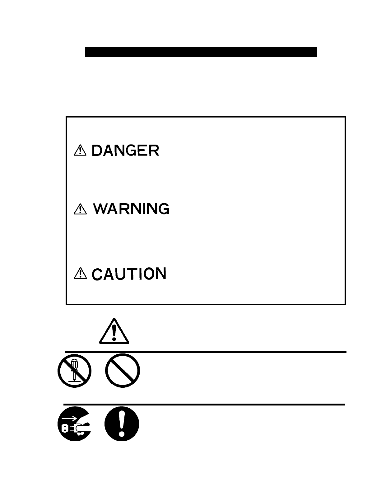
Example of alert symbols
This symbol indicates that ignorance of the
symbol and the instruction given together wit
it or erroneous on the product may cause a
imminent hazard which directly results i
personal serious injury or death.
This symbol implies a factor that may cause
personal serious injury or death due to
ignoran ce of the s ymbol and of th e instru ctions
given together with it or erroneous operations
of the product.
This symbol implies a factor that may cause
ersonal injury or property damage due to
ignoran ce of the symbol and of the instructions
given together with it or erroneous operations
on the
roduct.
This symbol indicates CAUTION (includes DANDER and
WARNING), the pictures in the triangle show caution
details.(The left picture shows a general warning .)
These symbo l ind icate act ion s that must not be perfor med.
Carefully read the given instructions and DO NOT carr
out these actions. (The left picture shows DO NOT
DO NOT
DISASSEBLE
DO NOT
PERFORM
DISASSEMBLE.)
These sym bol indicate actions that must be followed.
Carefully read the given instructions and always carr
REMOVE
PLUG
2
INSTRUCTIONS
them out. (The left picture shows REMOVE PLUG.)
Page 5
1.2
p
m
y
r
n
r
p
y
p
r
r
k
p
r
jury
!
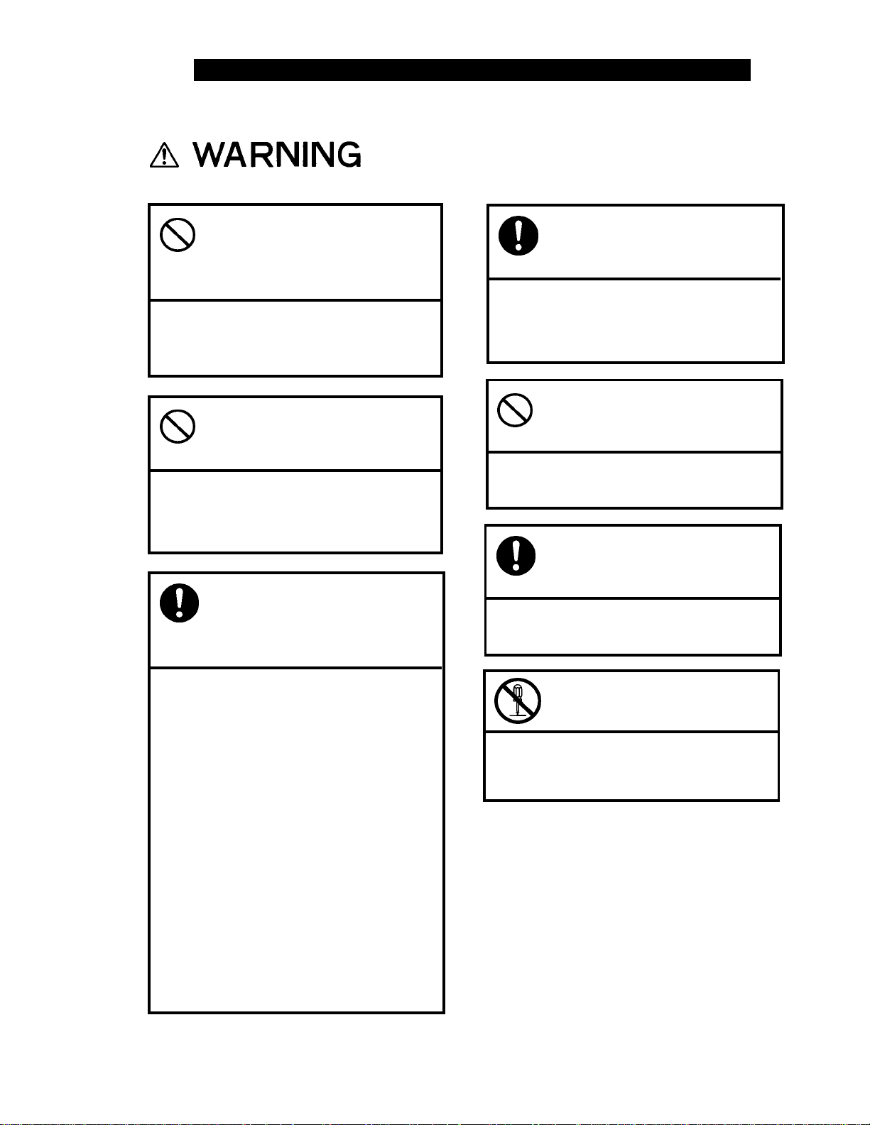
FOR SAFE OPERATION - IT IS IMPO RTANT YOU READ THIS
Telephone handling instructions
Otherwise, it may cause fire o
explosion
Otherwise, it may cause electric
shock or breakage.
Use this phone may cause electric
equipment to malfunction.
Examples of sensitive electronic
equipment include:
Hearing aids, medical apparatus
(pacemakers included), fire alarms,
automatic doors and othe
automatic control equipment.
If you are using a pacemaker o
some other medical apparatus, as
medical apparatus makers or dealers
about the effect which will be
caused by the radio wave from the
tele
Do not turn this telep hone o
where there is dust o
flammable substance such as
ropane gas or gasoline.
Do not insert any metal
ieces or for eign matter into
crevices on this phone.
Do not turn this telephone on
near electronic equipment
that uses sensitive controls
or weak signals.
hone.
When using in hospitals,
always follow the directions
Otherwise, use of telephone ma
of that medical facility
adversely affect medical electronic
equipment.
Do not give it a strong shock
or throw it.
Otherwise, it may cause breakage.
In the event that smoke (or
strange odors) comes fro
this telephone, immediatel
Otherwise, continued use may cause
fire. Take it to the dealer
romptly.
Do not disassemble or
modify this telephon e.
Otherwise, it may cause damage o
an accident such as fire or in
.
3
Page 6
N
y
p
p
y
g
b
n
FOR SAFE OPERATION- IT IS IMPORTANT YOU READ THIS (conti nue )
Otherwise, it may cause injury b
tumblin
ever attempt to dry your
telephone if it is gets wet b
lacing it in a microwave
oven, also never place this
hone in or on microwave
ovens, high voltage
containers or electronic
cooking equipment.
Do not get on this telephone.
(Especially be careful with
small children.)
or breakage.
Do not put this telephone i
a dusty, humid or hot place.
Otherwise, it may cause a fire or a
reakage.
Do not put this telephone
near heaters or fir es.
Otherwise, it may cause a breakage.
4
Page 7
1.3
b
r
b
r
r
p
jury
b
r
g
p
jury by
r
t
!
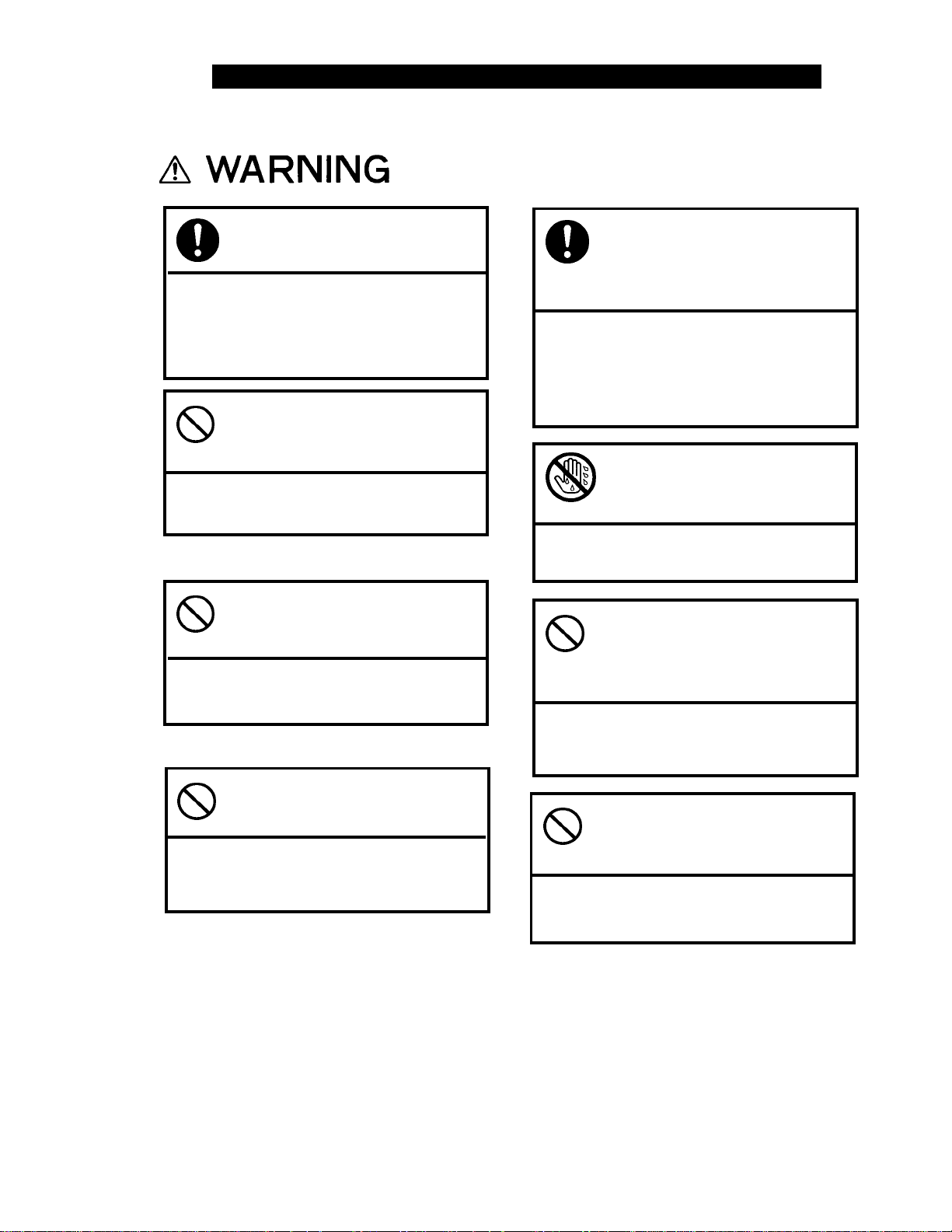
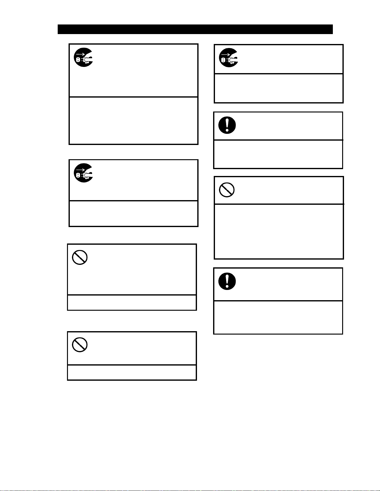
FOR SAFE OPERATION - IT IS IMPO RTANT YOU READ THIS
AC Adapter handling instructions
Connecting to the wrong powe
source may cause a fire or breakage.
Otherwise, it may cause breakage,
dire or in
Otherwise, it may cause electric
shock or breaka
Otherwise, it may cause breakage
and in
Always use the designed
ower source.
Do not make a short circuit
etween the DC output
terminals.
.
Do not insert any metal
ieces or for eign matter into
crevices on this phone.
e.
Do not swing the AC adapte
by holding the cord.
hitting you or others.
In case of dropping or
breaking AC adapter,
immediately unplug AC
adapter form AC outlet.
Otherwise, it may cause an electric
shock or breakage. Take it to the
dealer promptly.
Do not handle AC adapter or
DC plug of the AC adapte
with wet hand.
Otherwise, it may cause an electric
Do not damage AC adapter
y forcefully bending o
undling the AC adapte
Otherwise, it may cause an electric
shock or fire.
Do not place hea vy items on
AC adapter cord and do no
modify it.
Otherwise, it may cause an electric
shock or fire.
5
Page 8
FOR SAFE OPERATION- IT I S IMPORTANT YOU READ THIS (continue)
t
d
y
r
t
a
b
d
t
y
p
r
p
Otherwise, continued use may cause
a fire or electric shock.
Repairing by yourself is dangerous,
so take it to the dealer promptly.
Otherwise, it may cause a fire,
electric shock or emission.
Otherwise, it may cause a fire.
Otherwise, it may cause a fire.
In the event that smoke o
strange odors from AC
adapter, unplug the AC
Adapter from the AC outle
immediately.
If the AC adap ter is expose
to water, unplug the AC
adapter from the AC outle
immediately.
Do not use table tap,
divergence point o
divergence socket adapter to
ut many loads on one AC
outlet.
Do not leave pr use in direc
sunshine or places with high
temperature.
Otherwise, it may cause a fire,
electric shock and breakage.
Using AC adapter may cause
reakage.
(Especially, be careful with small
children.)
Otherwise, it may cause injury b
tumbling or breaking.
Pulling the AC adapter by its cor
may cause cord damage, with ma
result in fire or sock.
Unplug AC adapter from AC
outlet during thunder s hower.
Always use the designated
AC adapter.
Do not get on the AC
ter.
ada
Always unplug the AC
adapter to be by hold1ng
its case.
6
Page 9

1.4
!
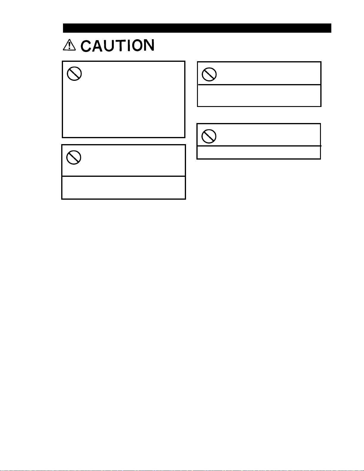
CAUTION OF USING
About water and rain
Do not use it in bathroom or plunge it into water.
Try to avoid telephone f rom getting wet by rain d rops etc.
If the phone gets wet, immediately wipe it with dry cloth.
!
Operating environment
You may hear some noise when cars or motor cycles pass by.
You may hear some noise or your phone call may be cut off if you use it by OA
equipment or electrical equipment.
You may hear some noise or your phone call may be cut off if you use it near a
microwave oven because of the electromagnetic waves.
If you use this telephone near the TV or radio, the screen may get messy or you
may hear some noise.
Try to use this telephone where it can get strongest radio wave.The usable area can
be restricted by the surrounding environment (wall, furniture etc.).
Radio waves can be jammed by material of furniture, so avoid using it near them.
7
Page 10

1.5
FEATURES OF DESKTOP TELEPHONE UTS600
UTS600 Desktop Telephone is a digital wireless telephone that incorporated PHS digital
cordless-phone technology in an ordinary touch-tone telephone.
UTS600 connects wirelessly to existing PHS network rather than a landline.
!
UTS600 operates just like an ordinary wire-line telephone.
!
You pick up the handset, hear a dial tone, and enter the phone number on the keypad
and waits for a connection.
UTS600 includes common wire-line phone features such as call waiting, redial and
hook flash, which can be accessed with a single key.
!
Benefits
• High Voice Quality
• Removable Whip Antenna
•
External Directional High-gain Antenna (Option, Ga=10dBi)
•
External Power Supply Unit with built-in back-up battery (Option)
•
External Earphone & Microphone Jack fo r FAX
•
3 Function keys
8
Page 11

1.6
CHECK PACKEAGE CONTENTS
Check package components after opening bo x.
AC Adapter
Desktop Telephone Whip Antenna
9
Page 12

1.7
NAMES AND FUNCTIONS
1 2
4
8
3
5
6
9
1 Earphone/Microphone Jack
2. DC IN Jack
3. Ringer Volume Switch
4. REDIAL key
5. PAUSE key
6. FLASH Key
7. Antenna Connector
8. Handset
9. Keypad
7
10
Page 13

a. Earphone/Microphone Jack
Connect earphone and exter nal microphone instead of handset receiver and
microphone.
b. DC IN Jack
DC Power supply connector for telephone.
Connect DC plug of attached AC adapter
c. Ringer Volume Switch
Select Ringer Sound Level by this switch to "High" or "Low".
d. REDIAL Key
Press this k ey to place a call by redial.
e. PAUSE Key
Press this key to hold a conversation.
f. FLASH Key
Press this k ey to use "Hook Flash" function.
g. Antenna Connector
Connect attached whip antenna or an external high gain antenna (optio n).
h. Handset
i. Key Pad
11
Page 14

2. OPERATION
2.1 PREPARATION
Connect Whip Antenna to Desktop Telephone antenna connector.
Desktop Telephone
Flex the Whip Antenna as shown below.
Insert AC plug of AC adapter into AC outlet, and insert DC plug into the Desktop
Telephone DC IN jack..
DC Plug
Antenna Connector
Whip Antenna
AC Adapter
To AC Outlet
Desktop Telephone
12
Page 15

2.2 Antenna Orientation
Careful placement of the antenna is necessary to ensure clear reception. Position the
antenna so that it is:
•
In clear view of a Radio Port
•
Not blocked by buildings, summer foliage nor heavy
traffic of large vehicles
•
At least 2 meters in height, use Coverage Map and
on-site measurements to determine exact height,
usually 2 meters or higher
•
Directed towards the strongest RSS measurement,
for directional antenna only
•
On a wall or pole that is sufficiently strong, make
sure wall or pole can withstand winds common to
the area
•
Away fr om other objects su ch as poles, trees,
buildings, and so on that block the signal from the
Radio Port; in general the minimum distance is 750
mm.
Antenna Type Determination Guidelines
The Cover age Map shows Radi o Port locations an d the area cover ed by the RP. Th e
type of antenna installed depends on its distance from the Radio Port. In gener al:
If distance is… Then use…
Less than 500m 4.5 dBi omni or directional
antenna
Between 400m and 700m 7 dBi omni or directional
antenna
Greater than 700m 10 dBi directional antenna
Table 2-1: Antenna Type Determination Guidelines
There may be exceptions to the requirements in Table 2-1 identified by on-site RSS
measurements and/or by the specific r adio environment.
13
Page 16

Main Unit Site Selection
Choose a suitable locat ion for the FSU Main Unit. Make sure the site will not expose
the device to:
• Direct sunlight
• Dampness or moisture
• Dust
• Magnetic fields
• Vibration
• Extremes of heat, cold or humidity.
Install t he FSU on a stable s urface, such as a d esk or wa ll. Co nsider the length o f the
AC Adapter cord in determining the Main Unit’s location. To avoid possible
interference from the connected telephone, make sure the Main Unit is installed at least
1 meter away. To minimize the length of coaxial cable between the main unit and the
antenna, position the indoor main unit as close as possible to the outdoor antenna.
Note : Make sure that the FSU Main Unit is positioned so that the green
LEDs are visible to the subscriber. When reporting tro ub l e, th e
subscriber will be asked the status of the LEDs.
Installation Accessories, Sta ndard and Special Tools
This sectio n lists all t he equipment ne eded for and FSU installation . Be sure to have
all of these items on hand before beginning.
Accessories:
•
Coaxial cable
•
Coaxial cable connector (2 pieces)
•
Marker
•
PVC tape
•
Self-adhesive rubber tape
•
Earth cable
•
Solderless grounding terminal (optional)
•
Bracket for cable
14
Page 17

• U-bolt for pole mount
• Terminal lug
• Terminal lug crimper
Note : In areas where lightning may strike, a lightning p rotector is
required.
Standard Installat i on Tools:
• Wire cutter
• Adjustable wrench
• Pliers
• Cutter
• Flat screwdriver
• Phillips (or Plus) screwdriver
• Electric drill
• Step ladder
• AC power extension cord
Special Tools for Cable Termination:
• Cable stripper
• Crimper
Antenna Orientat i on Instruments:
• Map
• Compass
• Binoculars
Measuring Receiver or Equivalent:
•
Measuring receiver
•
Memory card
•
AC adapter
•
Adapter (3-poles→2-poles conversion)
15
Page 18

• Coaxial cable adapter TNC-J/SM-J (optional)
• 5 meters of coaxial cable (optional)
• Power cable
Coaxial Cable Installation
Once the locations for the antenna and the main unit have been determined, use the
procedures in this section to install the cable.
1. Measure and cut a length o f cab le to fit between the
main unit and the antenna.
2. Run the cable between the main unit and the
antenna.
3. Using the cable strip per, strip both ends of the
coaxial cable. Refer to the figure below for exact
dimensions to strip.
Figure 2-1: Stripped Coaxial Cable
4. Carefully mount the coaxial cable terminals onto the
5. Affix the cable terminals using the crimper.
6mm
cable ends.
6mm
3mm
16
Page 19

Antenna Installa ti on
NOTE : The antenna sho wn in this manual is one of the three types of
antennae used in the UTStarcom-WLL system.
1. Unpack the FSU Antenna and accessories. Make
sure all parts are in good condition . The FSU
Antenna and accessories are shown in Figure 2-2.
(1) Antenna (1) Bracket
(2) Bolt (M6)
(2) Hexagon Nut
Figure 2-2 : FSU Antenna and Accessories
(2) Spring Washer
(4) Plain Washer
(2) Screws
(2) small Plain Washer
(2) small Spring Washer
17
Page 20

2. Assemble the FSU antenna by attaching the bracket
to the antenna according to Figure 2-3.
Figure 2-3: Antenna Bracket Assembly
3. After installing the antenn a, use the PHS Signal
Analyzer to check the receiving signal level.
Measure the reception level (RX LVL) at the TNC
connector on the FSU. Target values are as
follows:
• RX LVL: more than -78dB m (35d BµV)
• Frame Error Rate: less than 2%
18
Page 21

4. At the site selected for th e FSU antenna, tentativ ely
mount the antenna and take several RSS
measurements approximately 15 cm from the
antenna. Pos ition the an tenna where it receives that
strongest signal. Then mount the antenna on a pole.
Refer to the figure below for assembly of the bracket
onto the pole
Weep Hole
Figure 2-4 : Antenna Mounted On Pole
Note : Make sure that the weep hole is po sition ed at the lower edge of the
antenna bracket as shown in Figure 2-4.
5. After installing the antenn a, use the PHS Signal
Analyzer to check the receiving signal level.
Measure the reception level (RX LVL) at the TNC
connector on the FSU. Target values are as
follows:
• RX LVL: more than -78 dBm (35
dBµV)
• Frame Error Rate: less than 2%
19
Page 22

WARNING : DEPENDING O N LOCATION, IT MAY BE
NECESSARY TO GROUND THE ANTENNA TO
PREVENT DAMAGE BY LIGHTNING. REFER TO
THE FIGURE BELOW FOR A DIAGRAM O F THE
EARTH CABLE CONNECTION.
Terminal Lug
Figure 2-5 : Earth C able Connection
6. Attach a terminal lug to the lower bracket screw and
tighten screw.
7. Plug insulated cop per wire into the terminal lug and
use the terminal lug crimper to affix the copper wire
to the terminal lug.
8. Attach the other end o f the copper wire to a copper
clad rod as shown in the figur e above.
AWG 12
copper wire
insulated
6 inches above ground
ground line
5 ft. by .5 inch
copper clad rod
20
Page 23

9. Connect the coaxial cable to the antenna as shown in
Figure 2-6.
Coaxial Cable
Figure 2-6 : Coaxial Cable Connection to Antenna
10. Wrap the cable connection first with the
self-adhesive rubber tape. Stretch the tape until it is
½ its original width. Then wrap the PVC tape around
the rubber tape.
2.3 OPERATION
Desktop Phone will start its function when you insert the DC plug into DC IN jack.
It will communicate with PHS base station au tomatically, and operation will be
available after few seconds.
Placing a Call
!
Pick up handset.
Dial tone will be heard from the handset receiver.
Dial a telephone number of your party.
Ring-back ton e will be heard from handset receiver.
When your party answer your call, con vers ation will be available.
Hang up the handset when you finish the conversation.
You can call the party you last called by depressing "REDIAL" key for less than
1 second after hearing dial ton e.
21
Page 24

!
Receive a Call
Ringing tone will be heard from desktop telephone when it receive a call.
Conversation will be av ailable when you pick up the handset.
Placing a call on hold
!
Place a call on hold by depressing "PAUSE" key when you want to temporarily
stop the conversation.
While the other party is placed on hold, they can not hear you.
They hear a hold melody dur ing holding.
You can go back to the conv ersation by depressing "PAUSE" key again.
!
Using the Flash function
You can catch the another call d uring conversation by depressing "FLASH" key.
3. MAINTENANCE
Whip it with a dry soft cloth.
When the dirt is too much, use a diluted neutral detergent with a well wrung towel,
then wipe with a dry soft cloth.
Do not use benzene, thinner or alcohol.
It may cause color-change or deterioration of the paint or writing.
4. SPECIFICATIONS
Radio frequency band 1,900MHz
Transm ission power 10mW
Power source DC 4V, 300mA
External dimensions Approximately 197 (width) x 162 (depth) x 85.5 (height) mm
Mass Approximately 650g
22
 Loading...