

Page 1

UT-300R2 ADSL2/2+Modem
USER GUIDE
UTStarcom, Inc.
Page 2

Copyright © 2004 UTStarcom, Inc. All rights reserved.
No part of this documentation may be reproduced in any form or by any means or
used to make any derivative work (such as translation, transformation, or
adaptation) without prior, express and written permission from UTStarcom, Inc.
UTStarcom, Inc. reserves the right to revise this documentation and to make
changes in content from time to time without obligation on the part of UTStarcom,
Inc. to provide notification of such revision or changes.
UTStarcom, Inc. provides this documentation without warranty of any kind, implied
or expressed, including but not limited to, the implied warranties of merchantability
and fitness for a particular purpose. UTStarcom may make improvements or
changes in the product(s) and/or the program(s) described in this documentation
at any time.
UNITED STATES GOVERNMENT LEGENDS:
If you are a United States government agency, then this documentation and the
software described herein are provided to you subject to the following:
United States Government Legend:
commercial in nature and developed solely at private expense. Software is
delivered as Commercial Computer Software as defined in DFARS 252.227-7014
(June 1995) or as a commercial item as defined in FAR 2.101(a) and as such is
provided with only such rights as are provided in UTStarcom's standard
commercial license for the Software. Technical data is provided with limited rights
only as provided in DFAR 252.227-7015 (Nov 1995) or FAR 52.227-14 (June
1987), whichever is applicable. You agree not to remove or deface any portion of
any legend provided on any licensed program or documentation contained in, or
delivered to you in conjunction with, this User Guide.
UTStarcom, the UTStarcom logo, PAS, mSwitch, Airstar, WACOS, Netman, Total
Control, and CommWorks are registered trademarks of UTStarcom, Inc. and its
subsidiaries. The UTStarcom name, AN-2000, and the CommWorks logo are
trademarks of UTStarcom, Inc. and its subsidiaries.
Other brand and product names may be registered trademarks or trademarks of
their respective holders.
All technical data and computer software is
Any rights not expressly granted herein are firmly reserved.
Page 3

Contents
1 Overview......................................................................................... 1
Device Introduction...................................................................................... 1
Features ...................................................................................................... 2
2 Installation Planning...................................................................... 5
Packing List ................................................................................................. 5
Interfaces Introduction ................................................................................. 6
Front Panel .............................................................................................. 6
Rear Panel............................................................................................... 7
Cable Connections....................................................................................... 7
Connecting the ADSL Line....................................................................... 7
Connecting the UT-300R2 to the Ethernet LAN........................................ 8
Computer to UT-300R2 Connection ......................................................... 9
Hub or Switch to UT-300R2 Connection................................................... 9
Power on ................................................................................................... 10
3 Before Configuring UT-300R2..................................................... 13
Set up TCP/IP on Your PC......................................................................... 13
Set up Proxy Service ................................................................................. 14
Configure IP Settings on Your PC.............................................................. 14
First Time Log on....................................................................................... 15
4 Web-based Management............................................................. 17
Summary................................................................................................... 17
Configuring the WAN Connection .............................................................. 19
Configuring a Bridged Connection for the WAN...................................... 21
Configuring a Routed/Bridged Connection for the WAN ......................... 24
Configuring a PPP Connection for the WAN........................................... 26
Dynamic IP Address for the WAN Connection........................................ 28
Page 4

ii
Static IP Address for WAN......................................................................30
DHCP Configuration...................................................................................32
DHCP Server Settings for the LAN..........................................................33
Use the UT-300R2 for DHCP..................................................................34
Disabling the DHCP Server.....................................................................34
DNS Server Setting ....................................................................................34
Configuring the LAN Connection.................................................................35
Save New Settings .....................................................................................37
5 Advanced Configuration / Network Management......................39
Virtual Server Configuration........................................................................41
Special Application Configuration ...............................................................45
Configure a Filter Rule-IP Filters.................................................................48
Configuring a Filter Rule- MAC Filters.........................................................53
Configuring a Filter Rule-URL Blocking.......................................................56
Configuring a Filter Rule-Domain Blocking..................................................59
Firewall.......................................................................................................62
DMZ ...........................................................................................................64
DDNS.........................................................................................................65
RIP .............................................................................................................66
6 Tools..............................................................................................67
Administrator’s Settings..............................................................................67
Configure System Time ..............................................................................68
Save UT-300R2 Configuration Settings ......................................................69
Save Configuration File to PC.....................................................................70
Load Saved Configuration Files..................................................................71
Restore Factory Default Settings ................................................................72
Firmware Update........................................................................................72
7 UT-300R2 Status Information ......................................................75
Log.............................................................................................................75
Page 5

iii
Traffic Statistics ......................................................................................... 76
Diagnostics................................................................................................ 77
8 Attachments ................................................................................. 79
Technical Specifications............................................................................. 79
Glossary .................................................................................................... 82
Page 6

Overview
1
1
The UT-300R2 provides integrated voice and data services over
ADSL (Asymmetrical Digital Subscriber Loop) WAN (Wide Area
Network) connection.
Device Introduction
The UT-300R2 ADSL UT-300R2 is designed to provide a
simple and cost-effective ADSL Internet connection for
individual computers through the Ethernet ports, or use it to
bridge your Ethernet LAN to the Internet. The UT-300R2
combines the benefits of high-speed ADSL technology and LAN
IP management in one compact and convenient package.
ADSL technology enables many interactive multi-media
applications such as video conferencing and collaborative
computing.
The UT-300R2 is easy to install and use. The UT-300R2
connects to computers or an Ethernet LAN via a standard
Ethernet interface. The ADSL connection is made using
ordinary twisted-pair telephone line with standard connectors.
Multiple PCs can be networked and connected to the Internet
using a single Wide Area Network (WAN) interface and single
global IP address.
Page 7
2 Chapter 1 Overview
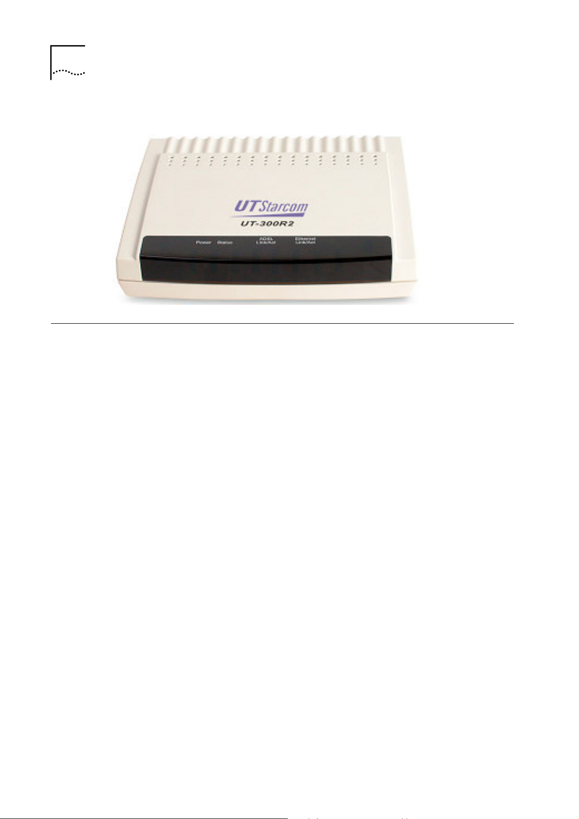
Figure 1
Device Appearance
Features
• Data rates up to 26 Mbps downstream
• Bridging and routing capabilities
•
• Firewall with Dynamic Host Configuration Protocol (DHCP),
• Supports ADSL, ADSL2, ADSL2+
• DSL Forum TR-048-compliant DSL CPE auto-
• UPnP for seamless network interconnectivity
• Comprehensive networking protocol support includes
PPP and tunneling features
Network Address Translation (NAT), Point-to-Point
Tunneling Protocol (PPTP), and Layer 2 Tunneling
Protocol (L2TP).
configuration
DHCP, PPPoE, PPPoA, and RIP
• Friendly web-based graphical user interface for
configuration and management
Page 8

Chapter 1 Overview
3
• Supports up to eight simultaneous virtual connections for a
single ADSL account
• Supports T1.413 issue 2, G.dmt and G.lite standards
• Auto-handshake and rate adaptation for different ADSL
flavors
• Widest range of DSLAM interoperability
• Supports bridged Ethernet over ATM (RFC 2684)
• Upgradeable firmware through web
Page 9

2
2
Before installing the UT-300R2, you should gather information
and equipment needed to install the device, then Install the
hardware as instructed, connect the cables to the device and
power on the UT-300R2. Prior to accessing the web-based
software built into the UT-300R2, you should check the IP
settings on your computer and change them if necessary.
Installation Planning
Packing List
Please check the package contents by comparing them with the
following list:
• One UT-300R2
• One telephone line
• One straight-through Ethernet Cable
• One Power Adapter
• One User CD-ROM
• One Splitter
Page 10
6 Chapter 2 Installation Planning
Interfaces Introduction
Front Panel
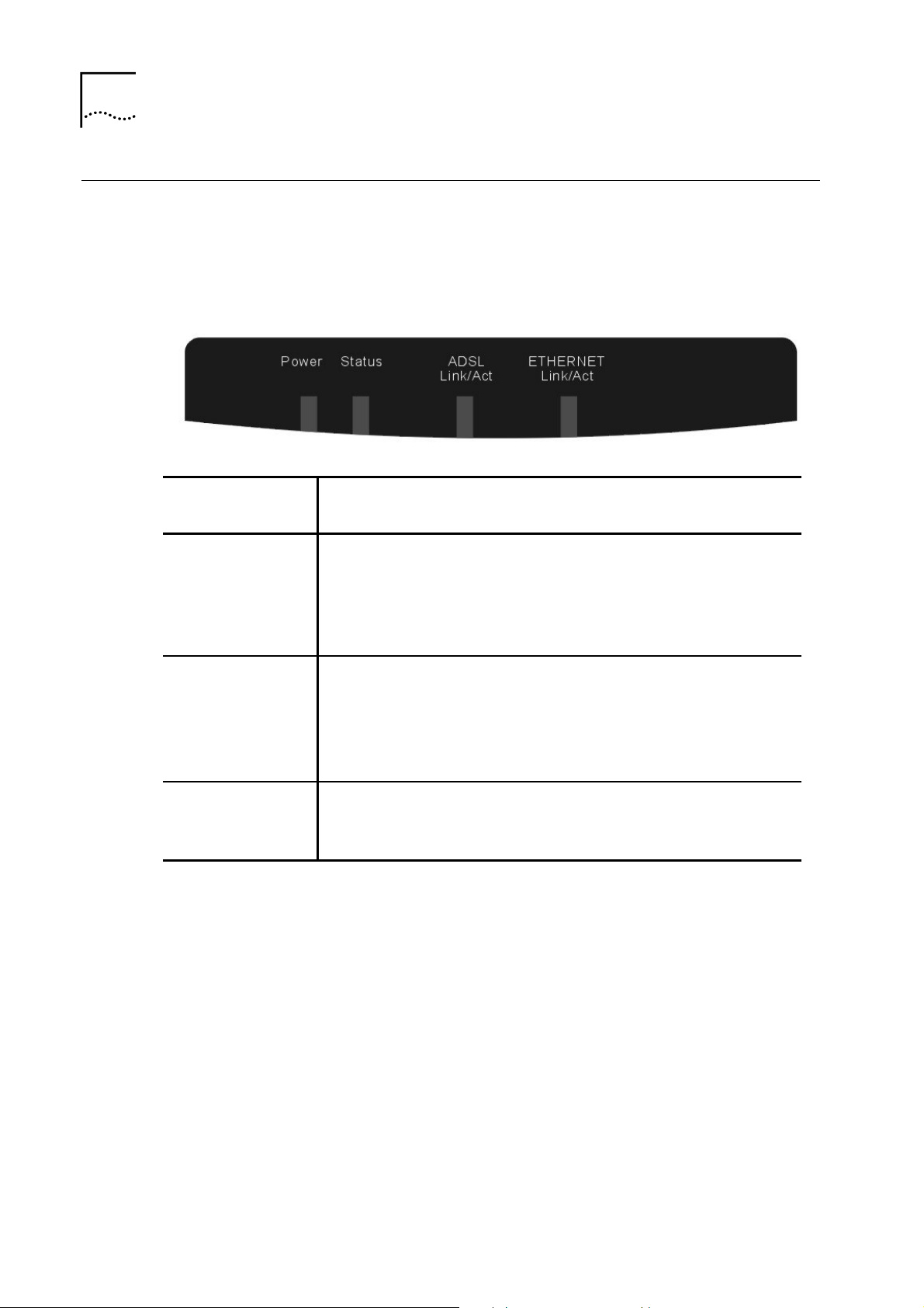
Figure 2 Front Panel
Power
Status
ADSL:
Link/Act
ETHERNET:
Link/Act
Steady green light indicates the unit is powered on.
When the device is powered off this remains dark.
Lights steady green during power on self-test
(POST). Once the connection status has been
settled, the light will blink green. If the indicator
lights steady green after the POST, the system has
failed and the device should be rebooted.
Steady green light indicates a valid ADSL
connection. This will light after the ADSL
negotiation process has been settled. A blinking
green light indicates activity on the WAN (ADSL)
interface.
A solid green light indicates a valid link on startup.
This light blinks when there is activity currently
passing through the Ethernet port.
Page 11
Rear Panel
Chapter 2 Installation Planning
7
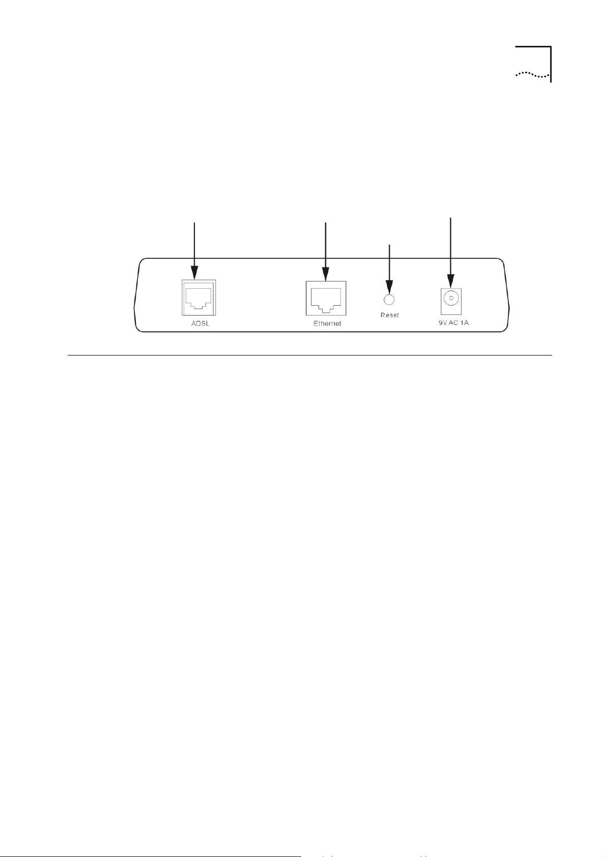
Figure 3
ADSL port Connect to the
ADSL line
Rear Panel
Cable Connections
After verifying proper environmental conditions such as
temperature, humidity and power supply, users may start the
cable connections as following.
Ethernet port - to your
PC’s Ethernet port
Factory Reset
Button
Power input - Connect
power adapter here
Connecting the ADSL Line
Use the ADSL cable included with the UT-300R2 to connect it
to a telephone wall socket or receptacle. Plug one end of the
cable into the ADSL port (RJ-11 receptacle) on the rear panel of
the UT-300R2 and insert the other end into the RJ-11 wall
socket. If you are using a low pass filter device, follow the
instructions included with the device or given to you by your
service provider. The ADSL connection represents the WAN
interface, the connection to the Internet. It is the physical link to
the service provider’s network backbone and ultimately to the
Internet.
Page 12

8 Chapter 2 Installation Planning
Connecting the UT-300R2 to the Ethernet LAN
The UT-300R2 may be connected to a single computer or
Ethernet device through the 10BASE-TX Ethernet port on the
rear panel. Any connection to an Ethernet concentrating device
such as a switch or hub must operate at a speed of 10/100
Mbps only. When connecting the UT-300R2 to any Ethernet
device that is capable of operating at speeds higher than
10Mbps, be sure that the device has auto-negotiation (NWay)
enabled for the connecting port.
Use standard twisted-pair cable with RJ-45 connectors. The RJ45 port on the UT-300R2 is a crossed port (MDI-X). Follow
standard Ethernet guidelines when deciding what type of cable
to use to make this connection. When connecting the UT-300R2
directly to a PC or server use a normal straight-through cable.
You should use a crossed cable when connecting the UT300R2 to a normal (MDI-X) port on a switch or hub. Use a
normal straight-through cable when connecting it to an uplink
(MDI-II) port on a hub or switch.
The rules governing Ethernet cable lengths apply to the LAN to
UT-300R2 connection. Be sure that the cable connecting the
LAN to the UT-300R2 does not exceed 100 meters.
Page 13
Chapter 2 Installation Planning
Computer to UT-300R2 Connection
9
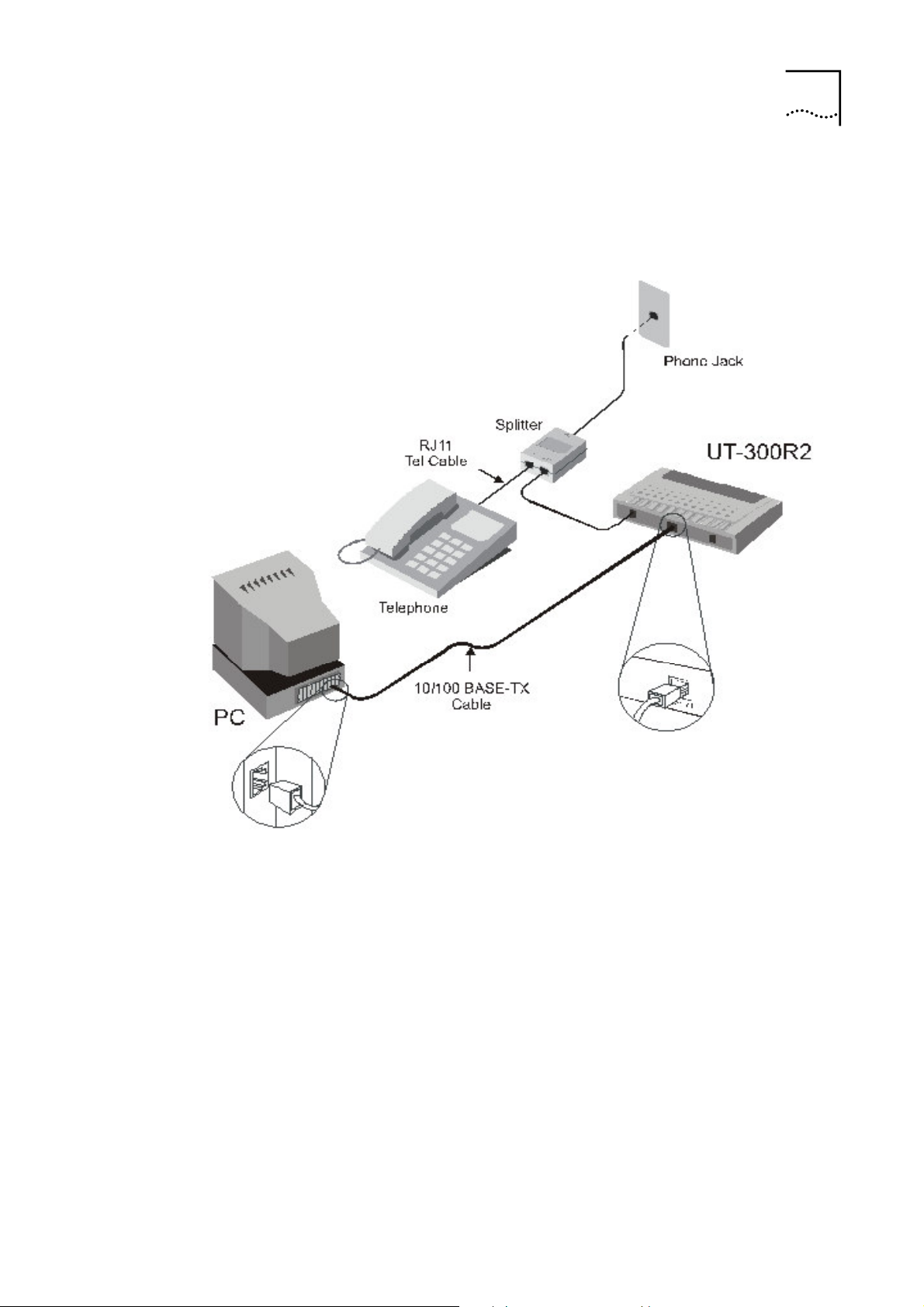
Figure 4
Computer to UT-300R2 Connection
You can connect the UT-300R2 directly to a 10/100BASE-TX
Ethernet adapter card (NIC) installed on a PC using the
Ethernet cable provided as shown in this diagram.
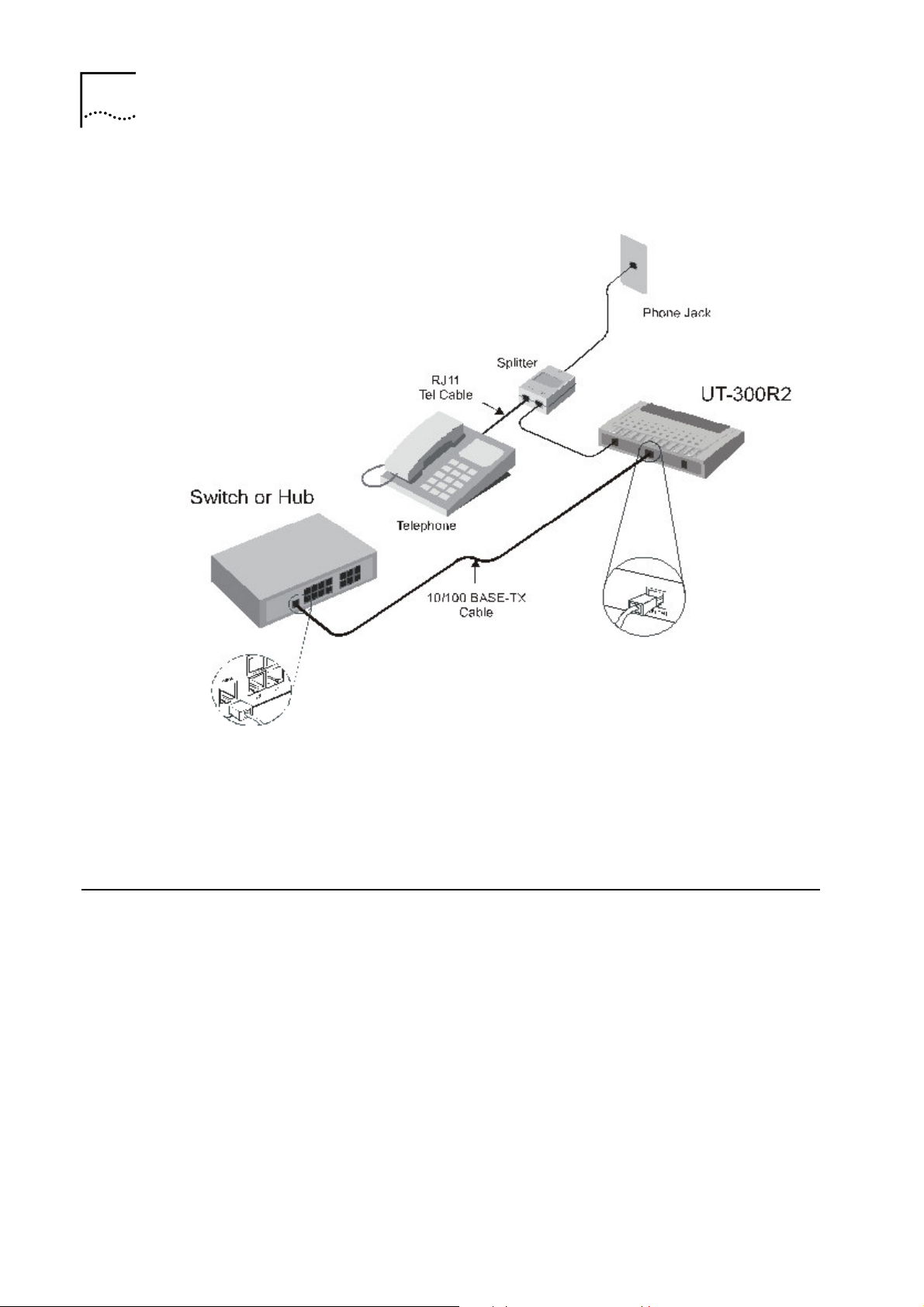
Hub or Switch to UT-300R2 Connection
Connect the UT-300R2 to an uplink port on an Ethernet hub or
switch with a straight-through cable as shown in the diagram
below:
Page 14
10
Chapter 2 Installation Planning
Figure 5
Hub/Switch to UT-300R2 Connection
If you wish to reserve the uplink port on the switch or hub for
another device, connect to any on the other MDI-X ports (1x, 2x,
etc.) with a crossed cable.
Power on
1 To power on the UT-300R2, please follow the steps as
2 Insert the AC Power Adapter cord into the power
instructed:
receptacle located on the rear panel of the UT-300R2 and
plug the adapter into a suitable nearby power source.
Page 15

Chapter 2 Installation Planning
11
3 You should see the Power LED indicator light up and
remain lit. The Status LED should light solid green and
begin to blink after a few seconds.
Page 16

3
3
The factory default settings of UT-300R2 optimized all functions
so as to enable it to operate on most network conditions.
Usually, for the users with simple network topology, the default
settings can meet the basic requirements and don’t need to
change. In order to access the web-based software built into
the UT-300R2, you should check the IP settings on your
Before Configuring UT-300R2
computer and change them if necessary to access web-based
manager to configure the device.
Set up TCP/IP on Your PC
In order to configure your system to receive IP settings from the
UT-300R2 it must first have the TCP/IP protocol installed. If you
have an Ethernet port on your computer, it probably already has
TCP/IP protocol installed. Please follow the instructions to
check your IP protocol:
1 In Windows task bar, click the
Settings>Network and Dial-up Connection
Local Connection.
2 Click on
Properties
> Select Internet Protocol (TCP/IP)
Start
button, point to
> and click on
and then Click Properties.
3 Click on the button labeled use the following IP address,
then you can set the IP address and Subnet mask, for
example, 192.168.1.100 and 255.255.255.0.
Page 17

14
Chapter 3 Before Configuring UT-300R2
Note:
installed component, you must install it.
If Internet Protocol (TCP/IP) does not display as an
Set up Proxy Service
In Windows Internet Explorer, you can check if a proxy server is
enabled using the following procedure:
1 Click on the
Control Panel
2 In the
Options
3 Click the Connections tab and click on the LAN Settings
button.
Control Panel
START
.
icon
button, go to
window, double-click on the
Settings
and choose
Internet
4 Verify that the “
If it is checked, click in the checked box to deselect the
option and click OK.
Use proxy server
” option is NOT checked.
Configure IP Settings on Your PC
To use the web-based management software, launch your web
browser software and use the LAN IP address of the UT-300R2
to access the management software. The default LAN IP
address of the UT-300R2 is used in the Address bar of your
web browser window. Type in
address,
URL in the address bar should read: http://192.168.1.1
192.168.1.1
in the address bar of the browser. The
http://
followed by the default IP
Page 18
15
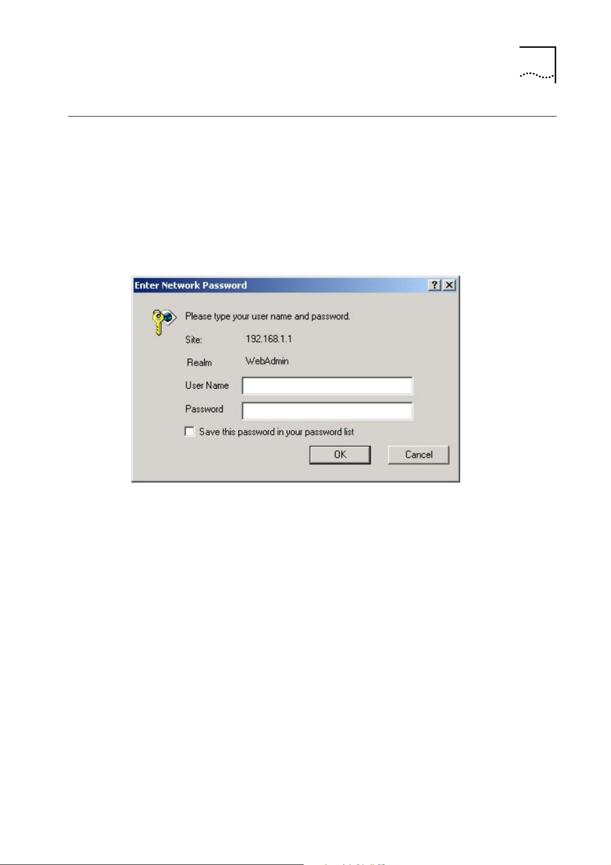
First Time Log on
After inputting the forgoing IP address on URL address bar, a
new window appears prompting you for a user name and
password needed to gain access the web configuration
manager.
Chapter 3 Before Configuring UT-300R2
Figure 6
Log On Interface
Use the default system user name:
admin
and password:
admin for first time set up. You can change the password once
you have established the ADSL connection. The user name and
password allows any computer on the same subnet as the UT300R2 to access the web configuration manger. This password
can also be used to Telnet to the device through the Ethernet or
the Internet interfaces.
Page 19

4
4
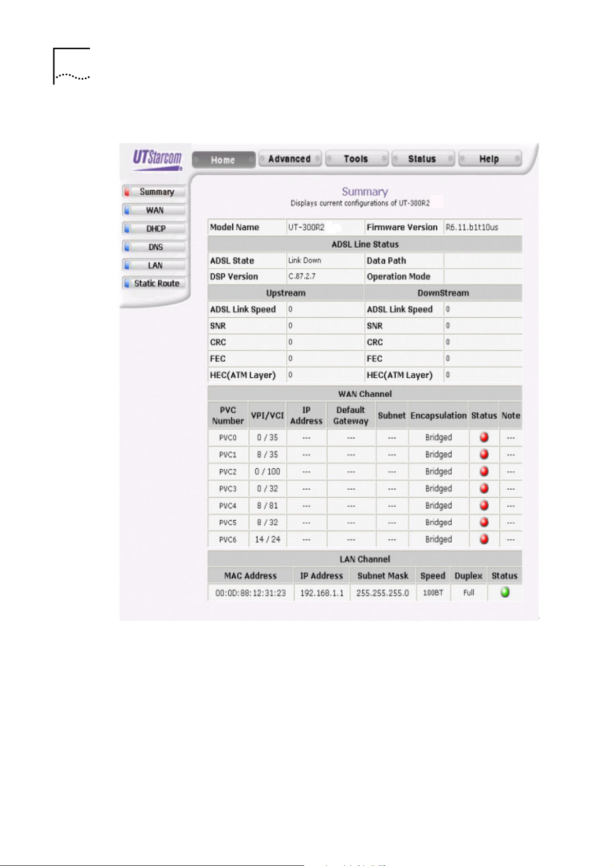
Summary
Web-based Management
When you successfully login the
display the UT-300R2’s current connection status − both for the
WAN (Internet) and LAN (your home network) connections, as
shown below. You can begin the process of configuring your
ADSL modem/UT-300R2 by clicking on the
upper left-hand corner of the first Web page displayed.
Summary
directory button will
WAN
button in the
Page 20
18
Chapter 4 Web-based Management
Figure 7
Web Manager – First Page
Each tab displays menu buttons located in the left hand panel
of the web interface. The table below lists the menus for each
directory in the web manager.
Page 21

Chapter 4 Web-based Management
19
Table 1
Options of Web-based page
Directory
Home
Advanced
Tools
Status
Help
Configuration and Read-only Menus
Click the Home tab to access the Summary, WAN,
DHCP, DNS, and LAN Configuration menus.
Click the Advanced tab to access the Virtual Server,
Application, Filter, Firewall, NAT, DDNS, and RIP
menus.
Click the Tools tab to access the Administrator
Settings (used to set the system user name and
password), System Time Configuration, System
Settings (load and save configuration files) and
Firmware menus.
Click the Status tab to view the Log, Diagnostic, and
Statistics information windows.
The Help menu presents links to pages that explain
various functions and services provided by the UT300R2.
Configuring the WAN Connection
To configure the UT-300R2’s basic configuration settings, you
can access the menus used to configure WAN, DHCP, DNS
and LAN settings from the
Home
Settings menu, click on the
hand side of the first window that appears when you
successfully access the web manager.
The WAN Settings menu is also used to configure the UT300R2 for multiple virtual connections. The next section
contains information on how to configure the UT-300R2 for
Multiple PVCs. Please note that most users will require only
directory. To access the WAN
WAN
link button on the upper left-
Page 22
20
Chapter 4 Web-based Management
single PVC. Select the connection type used for your account.
The menu will display settings that are appropriate for the
connection type you select. Follow the instruction below
according to the type of connection you select in the WAN
Settings menu. Your Internet Service Provider (ISP) should
provide the information you need to select the proper
connection type.
Figure 8
WAN Current Settings Menu
Select the connection type used for your account. The menu will
display settings that are appropriate for the connection type you
select. Follow the instruction below according to the type of
connection you select in the WAN Settings menu. Your Internet
Service Provider (ISP) should provide the information you need
to select the proper connection type.
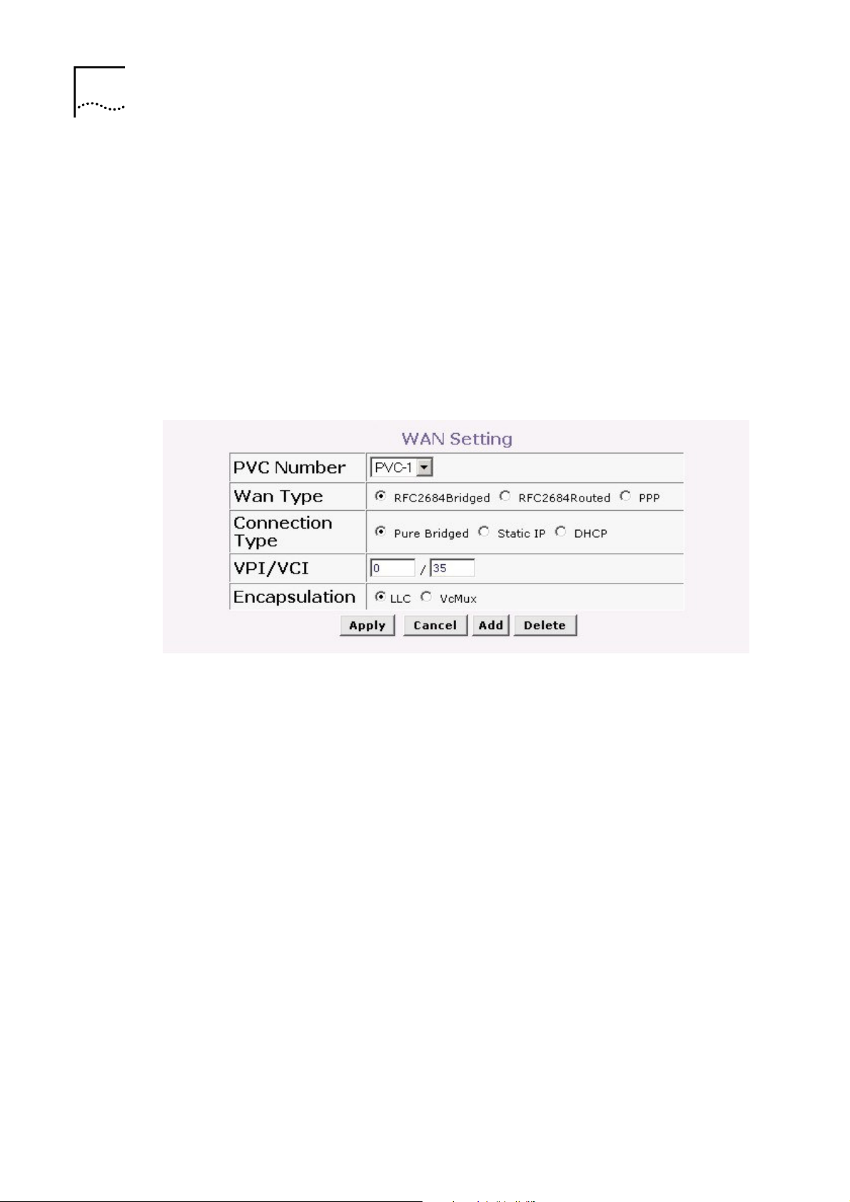
To change the current configuration of the UT-300R2, click the
button. This will open the menu shown below. Please note
Add
that the contents of this menu will change depending upon
which Connection Type you choose for this PVC.
Page 23
Chapter 4 Web-based Management
21
Figure 9 WAN Setting − Add menu
Note:
you can configure up to seven different connections on
your UT-300R2 ADSL Modem/UT-300R2 by assigning a
number to each configuration using the drop-down menu
corresponding to the PVC Number heading. This could be
useful if you have several ISPs and need to configure the UT300R2 differently for each. Most users will require only single
PVC, however.
Configuring a Bridged Connection for the WAN
A bridged connection between your ISP and your LAN (the
computers in your house or office) is the simplest type of
connection possible. The UT-300R2 will simply convert the
incoming and outgoing packets to the correct format for each
side of the connection (Ethernet for the LAN, ATM for the WAN).
For a bridged connection it will be necessary for most users to
install additional software (supplied by your ISP) on any
computer that will use the UT-300R2 for Internet access. The
additional software is used for the purpose of identifying and
Page 24
22
Chapter 4 Web-based Management
verifying your account, and then granting Internet access to the
computer requesting the connection (that is, the software
supplied by your ISP will handle giving your Username and
Password to the computer at your ISP that will then connect you
to the Internet). The connection software requires the user to
enter the User Name and Password for the ISP account. This
information is stored on the computer on the LAN, not in the
UT-300R2 for a bridged connection.
Follow the instructions below to configure a Bridged connection
for the WAN interface.
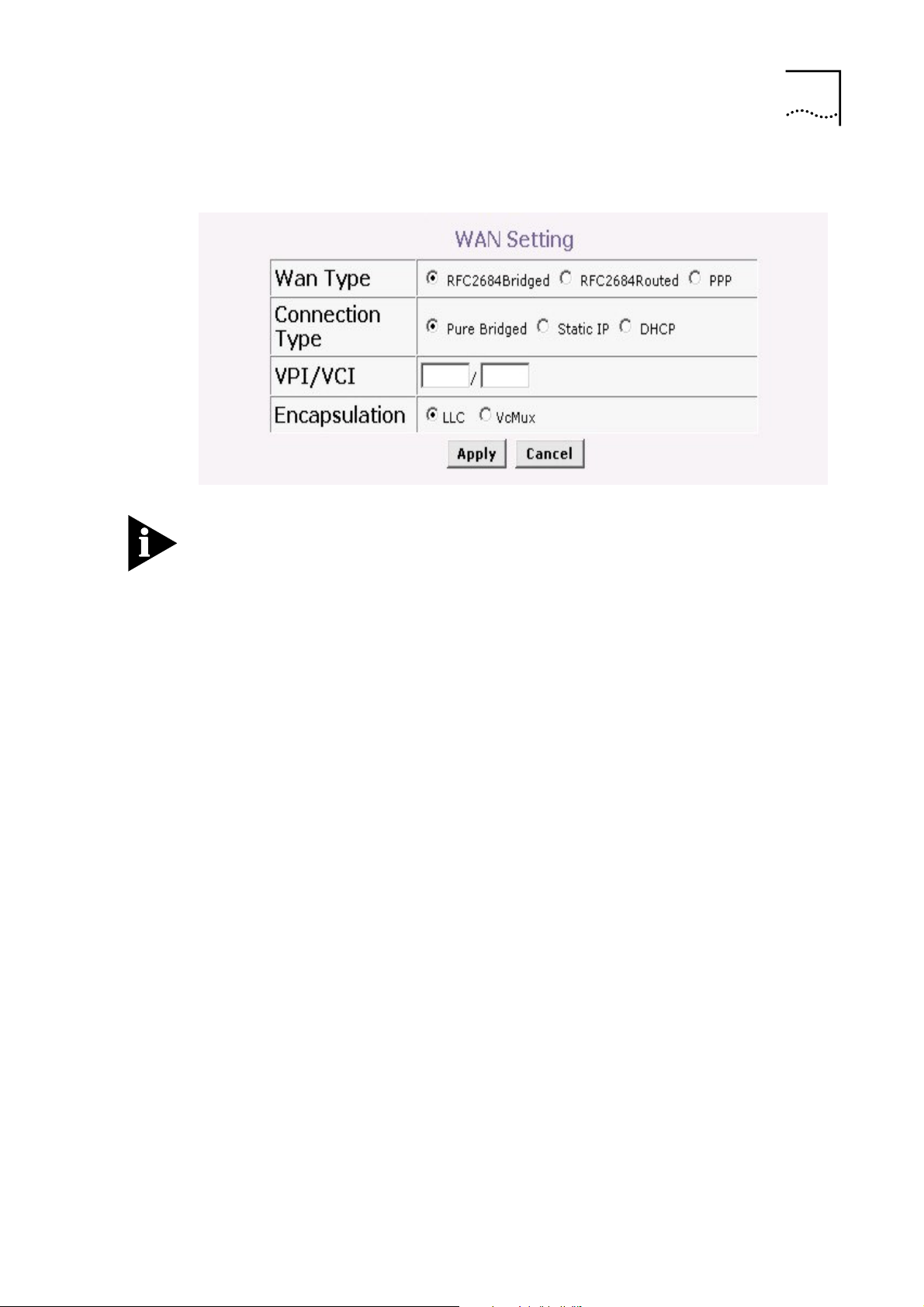
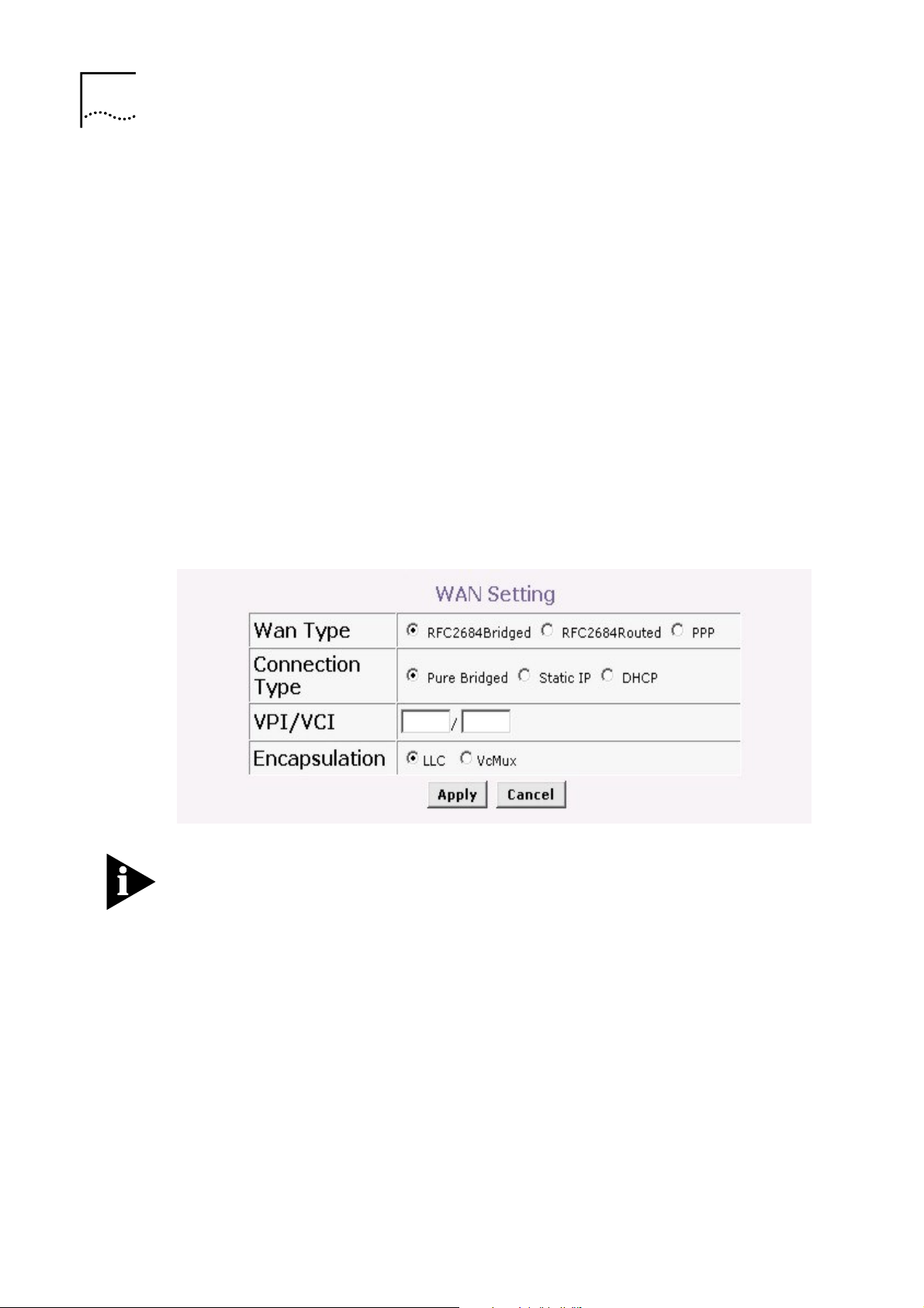
Figure 10 WAN Settings Menu – Pure Bridged Mode
Note:
Please note that the menu shown above will change
depending on which WAN Type and Connection Type you
select.
1 Click to select the
WAN Type
options list if your ISP uses DHCP to assign
RFC2684Bridged
radio button in the
you an IP address that is valid on the WAN (Internet). This
is the most common type of bridged connection offered by
ISPs.
Page 25

Chapter 4 Web-based Management
23
2 Also under the VPI/VCI, you will need to enter two
numbers, the
VCI
and
values. These numbers are
VPI
used to define a unique path for your connection. Your ISP
should give you the specific settings for the VPI and VCI
numbers to enter. Type in the correct values assigned by
your ISP.
3 Select the Encapsulation type (LLC or VcMux) radio
button that corresponds to the encapsulation in use by
your ISP.
4 When you are satisfied that all the WAN settings are
configured correctly, click on the
Apply
button.
5 The new settings must be saved and the UT-300R2 must
be restarted for the settings to go into effect. To manually
save and reboot the UT-300R2, click on the
Tools
directory tab and then click the
System
menu button. On
the menu that appears, click he Save & Restart button.
The UT-300R2 will save the new settings and restart.
Upon restarting the UT-300R2 will automatically establish
the bridged WAN connection.
Note:
Some accounts use PPP connection software for their
Internet service connection. If you have been given a CD with
PPP connection software, install this now as instructed by your
service provider. After the UT-300R2 has rebooted it will
negotiate the ADSL connection. Use the connection software to
log on to the ISP network and access the Internet.
Page 26

24
Chapter 4 Web-based Management
Configuring a Routed/Bridged Connection for the WAN
A routed bridged connection between your ISP and your LAN
(the computers in your house or office) is useful if packets sent
from the LAN to the WAN through the UT-300R2 must cross
part of another network in your ISP’s installation, before arriving
at a specific computer or network device, specified by an IP
address. Your ISP will need to give you the specific
Subnet Mask
, and Default Gateway address that packets
IP Address
destined for the Internet must be sent to. The UT-300R2 will
then manage both the necessary format conversion and direct
the outgoing packets to the destination you specify.
For a routed/bridged connection it will be necessary for most
users to install additional software (supplied by your ISP) on
any computer that will use the UT-300R2 for Internet access.
The additional software is used for the purpose of identifying
and verifying your account, and then granting Internet access to
the computer requesting the connection (that is, the software
supplied by your ISP will handle giving your Username and
Password to the computer at your ISP that will then connect you
to the Internet). The connection software requires the user to
,
enter the User Name and Password for the ISP account. This
information is stored on the computer on the LAN, not in the
UT-300R2 for a bridged connection.
Follow the instructions below to configure a Routed/Bridged
connection for the WAN interface.
Page 27

Chapter 4 Web-based Management
25
Figure 11
WAN Settings Menu – Routed/Bridged Mode
Note:
Please note that the menu shown above will change
depending on which WAN Type and Connection Type you
select.
1 Click to select the RFC2684Bridged radio button in the
WAN Type
options list if your ISP uses DHCP to assign
you an IP address that is valid on the WAN (Internet). This
is the most common type of bridged connection offered by
ISPs.
2 Also under the VPI/VCI, you will need to enter two
numbers, the
VCI
and
values. These numbers are
VPI
used to define a unique path for your connection. Your ISP
should give you the specific settings for the VPI and VCI
numbers to enter. Type in the correct values assigned by
your ISP.
Page 28

26
Chapter 4 Web-based Management
3 Select the
Encapsulation
type (LLC or VcMux) radio
button that corresponds to the encapsulation in use by
your ISP
4 Enter the IP Address, Subnet Mask, and Default Gateway
address as supplied by your ISP.
5 When you are satisfied that all the WAN settings are
configured correctly, click on the Apply button.
6 The new settings must be saved and the UT-300R2 must
be restarted for the settings to go into effect. To manually
save and reboot the UT-300R2, click on the
directory tab and then click the
the menu that appears, click he
System
Save & Restart
The UT-300R2 will save the new settings and restart.
Upon restarting the UT-300R2 will automatically establish
the bridged WAN connection.
Note:
Some accounts use PPP connection software for their
Internet service connection. If you have been given a CD with
PPP connection software, install this now as instructed by your
service provider. After the UT-300R2 has rebooted it will
negotiate the ADSL connection. Use the connection software to
log on to the ISP network and access the Internet.
Configuring a PPP Connection for the WAN
Tools
menu button. On
button.
Most ADSL accounts will use either the Point-to-Point Protocol
over Ethernet (PPPoE) or the Point-to-Point Protocol over ATM
(PPPoA) connection. Follow the instructions below to configure
the UT-300R2 to use a PPPoE or PPPoA for the Internet
connection. Make sure you have all the necessary information
Page 29

Chapter 4 Web-based Management
27
before you configure the WAN connection. See the table in the
first section of this manual for a summary of the information you
will need.
1 Select the
PPP
radio button to open the Point-to-Point
Protocol (PPP) menu.
2 Click to select either the
button in the
Type
options list.
3 Choose the
WAN Setting
Encapsulation
PPPoE
menu under the
type from the options of LLC
or the
PPPoA
radio
Connection
and VcMux radio buttons. If have not been provided
specific information for the Connection Type setting, leave
the default setting.
4 If you are instructed to use enable Default Route, this
setting specifies that the UT-300R2 be used to define the
default route to the Internet for your LAN. Whenever a
computer on the LAN attempts to access the Internet, the
UT-300R2 becomes the Internet gateway to the computer.
5 Under the
Password
Name will be in the form user@isp.com.au, your ISP may
assign the Password to you or you may have selected it
when you set up the account with your ISP.
6 The
Use DNS
the UT-300R2 will request DNS settings from your ISP’s
DNS server. If your ISP has provided a specific IP address
to use for DNS, you should select Disabled and manually
configure DNS settings in the DNS menu (see
DNS
below). You will not be able to access Internet web
heading, type the
PPP
User Name
and
used for your ADSL account. A typical User
is enabled by default. When this is enabled,
Configure
Page 30

28
Chapter 4 Web-based Management
sites until the DNS settings are properly configured. Be
sure to configure this before you save the new settings and
restart the UT-300R2.
7 When you are satisfied that all the WAN settings are
configured correctly, click on the
Apply
The new settings must be saved and the UT-300R2 must be
restarted for the settings to go into effect. To manually save and
reboot the UT-300R2, click on the
click the
System
menu button. On the menu that appears, click
Tools
directory tab and then
he Save & Restart button. The UT-300R2 will save the new
settings and restart. Upon restarting the UT-300R2 will
automatically establish the bridged WAN connection.
Dynamic IP Address for the WAN Connection
When the UT-300R2 is configured to use Dynamic IP Address
assignment for the WAN connection, a server on the ISP’s
network assigns the global IP address settings used for the
WAN connection. This is method is simply Dynamic Host
button.
Control Protocol (DHCP) for the WAN. The UT-300R2 can be
configured to be a DHCP client and obtain its IP settings
automatically from the DHCP server maintained by your ISP.
Follow the instructions below to configure the UT-300R2 to use
Dynamic IP Address assignment for the WAN connection.
Page 31

Chapter 4 Web-based Management
29
Figure 12
WAN Settings - Dynamic IP Address (DHCP)
1 From the
WAN Setting
page, select the PVC you want to
configure from the seven available PVCs, using the dropdown menu.
2 You can also specify the
this PVC by your ISP) that will be used to uniquely identify
this PVC to your ISP. You can also enter of modify these
two numbers later during the configuration process.
3 Click the
button, at the bottom of the page, to add the
Add
new configuration to the list of active PVCs. This will open
the
WAN Setting
4 Click to select the
configuration screen, shown above.
DHCP
Connection Type options list. The menu will change to
offer a different set of configuration options and will appear
VPI/VCI
numbers (assigned to
radio button listed in the
as shown above when DHCP is selected.
5 If you are instructed to use enable
ISP, click the
Enabled
radio button. This setting specifies
Default Route
by your
that this PVC (from the list of seven) on your UT-300R2 be
used to define the default route to the Internet for your LAN.
Page 32

30
Chapter 4 Web-based Management
Whenever a computer on your LAN attempts to access the
Internet, the UT-300R2 will use this PVC to direct packets
to the Internet, and this PVC will become the default
gateway to the Internet for your LAN.
6 Under the
Encapsulation
VcMux, as instructed by your ISP.
7 When you are satisfied that all the WAN settings are
configured correctly, click on the
8 The new settings must be saved and the UT-300R2 must
be restarted for the settings to go into effect. To manually
save and reboot the UT-300R2, click on the
directory tab and then click the
the menu that appears, click he
The UT-300R2 will save the new settings and restart.
Upon restarting the UT-300R2 will automatically establish
the bridged WAN connection.
Static IP Address for WAN
heading, select either LLC or
Apply
button.
Tools
System
Save & Restart
menu button. On
button.
When a PVC (of the available list of seven) on the UT-300R2 is
configured to use a Static IP Address assignment for the WAN
connection, you must manually assign a global IP Address,
Subnet Mask and Gateway IP Address used for the WAN
connection provided by this PVC. Most users will also need to
configure a DNS server IP setting in the DNS Settings
configuration menu (see below). Follow the instruction below to
configure the UT-300R2 to use Static IP Address assignment
for the WAN connection.
Page 33

Chapter 4 Web-based Management
31
Figure 13
WAN Settings - Static IP
1 From the WAN Setting page, select the PVC you want to
configure from the seven available PVCs, using the dropdown menu.
2 You can also specify the VPI/VCI numbers (assigned to
this PVC by your ISP) that will be used to uniquely identify
this PVC to your ISP. You can also enter of modify these
two numbers later during the configuration process.
3 Click the
button, at the bottom of the page, to add the
Add
new configuration to the list of active PVCs. This will open
the
WAN Setting
configuration screen, shown above.
4 Click to select the RFC2684Bridged radio button listed in
the
WAN Type
options list. The menu will change to offer
a different set of configuration options, as shown above.
5 Select the
, by clicking the radio button.
IP
Connection Type
from the options to be
Static
Page 34

32
Chapter 4 Web-based Management
6 Enter the appropriate
IP Address, Subnet Mask
and
Default Gateway
address as instructed by your ISP. Your
ISP should have provided these IP settings to you.
7 If you are instructed to use enable
ISP, click the
Enabled
radio button. This setting specifies
Default Route
by your
that this PVC (from the list of seven) on your UT-300R2 be
used to define the default route to the Internet for your LAN.
Whenever a computer on your LAN attempts to access the
Internet, the UT-300R2 will use this PVC to direct packets
to the Internet, and this PVC will become the default
gateway to the Internet for your LAN.
8 When you are satisfied that all the WAN settings are
configured correctly, click on the Apply button.
9 The new settings must be saved and the UT-300R2 must
be restarted for the settings to go into effect. To manually
save and reboot the UT-300R2, click on the
directory tab and then click the System menu button. On
the menu that appears, click he
The UT-300R2 will save the new settings and restart.
Upon restarting the UT-300R2 will automatically establish
the bridged WAN connection.
DHCP Configuration
To display the
the
Home
directory. Active DHCP Clients appear listed in the
DHCP Client Table
about DHCP clients includes the IP address, MAC address,
host name and lease time are displayed in the list.
DHCP Server
Tools
Save & Restart
menu, click the
DHCP
button.
button in
below the configuration menu. Information
Page 35

Chapter 4 Web-based Management
33
Figure 14
Configure DHCP server settings for the LAN
The three options for DHCP service are as follows:
1 You may use the UT-300R2 as a DHCP server for your
LAN.
2 You can disable DHCP service and manually configure IP
settings for all workstations.
You will use a DHCP service provided by your ISP, in which
case DHCP should be disabled on the UT-300R2.
DHCP Server Settings for the LAN
The default setting of UT-300R2 's DHCP server is disabled.
While you click to select the
DHCP Server
option, the device will become the default
Enabled
radio button under the
gateway for DHCP clients that connected to it. When the UT300R2 is used for DHCP it becomes the default gateway for
DHCP client connected to it. Keep in mind that if you change
Page 36

34
Chapter 4 Web-based Management
the IP address of the UT-300R2, you must change the range of
IP addresses in the pool used for DHCP on the LAN.
Use the UT-300R2 for DHCP
To use the built-in DHCP server, click to select the DHCP
Server
settings can be adjusted so that up to 253IP addresses are
available for use. The Starting IP Address is the lowest
available IP address (default = 192.168.1.2). If you change the
IP address of the UT-300R2 this will change automatically to be
1 more that the IP address of the UT-300R2. The
Address is the highest IP address number in the pool (default =
192.168.1.33). Select the
This is the amount of time that a workstation is allowed to
reserve an IP address in the pool if the workstation is
disconnected from the network or powered off. Lease time
options vary from 1 hour to 1 week. DHCP client workstations
on your LAN must be properly configured to use DHCP service.
Be sure to save the new settings.
option if it is not already selected. The IP Address Pool
Ending IP
Lease Time
from the pull-down menu.
Disabling the DHCP Server
To disable DHCP, click to select the
under the DHCP Server option and click on the Apply button.
Be sure to save the new settings
DNS Server Setting
The UT-300R2 is configured by default to forward the DNS
server address you enter in the DNS page, shown below, to all
DHCP clients on your LAN. When DNS is enabled, the DNS
Disabled
radio button
Page 37

Chapter 4 Web-based Management
35
clients on the LAN will automatically get DNS settings relayed
from the UT-300R2 as they are entered here. Alternatively, if
DNS Status
is disabled, workstations must be configured to
initiate DNS requests for each session, and therefore you must
configure DNS settings for the workstations.
Figure 15
Configure DNS IP address
Usually an ISP will provide you with one or two DNS server IP
addresses. Enter these IP addresses in the available entry
fields for the
Server
.
Primary DNS Server
and the
If you do not want to use the UT-300R2 as a DNS proxy agent,
change the
DNS Status
to Disabled.
When you have configured the DNS settings as desired, click
the
Apply
button. Be sure to save the settings.
Configuring the LAN Connection
The first step in configuring your LAN is to determine the IP
address scheme that the computers on your LAN will use. The
Secondary DNS
Page 38

36
Chapter 4 Web-based Management
192.168.1.x (where x can range from 2 to 254) IP address
range has been dedicated for home and small office use. The
UT-300R2 ADSL router is configured with a default IP address
of 192.168.1.1, and a subnet mask of 255.255.255.0. The next
IP address available for use on a LAN is 192.168.1.2. This is
why the IP address range begins with an x = 2, because when x
= 1, that identifies the UT-300R2 on your LAN. The IP address
where x = 255 has a special meaning (it is the broadcast
address for your LAN). When you configure PCs on your LAN,
the UT-300R2’s IP address (192.168.1.1) will become the
Default Gateway IP address for all PCs on your LAN.
You can configure the UT-300R2’s LAN IP address to any IP
addressing scheme that meets the needs of your LAN. Many
users will find it convenient to use the default settings together
with the DHCP service to manage the IP settings for their LANs.
The IP address of the UT-300R2 is the base address used for
DHCP. In order to use the UT-300R2 for DHCP on your LAN,
the IP address pool used for DHCP must be compatible with the
IP address of the UT-300R2. The IP addresses available in the
DHCP IP address pool will change automatically if you change
the IP address of the UT-300R2. See the next section for
information on DHCP setup, as described below.
So, if you want to use an IP addressing scheme that is different
from the 192.168.1.x/255.255.255.0 scheme, you will need to
give the UT-300R2 ADSL router a new IP address. This is done
on the
LAN Settings
To access the
LAN Settings
page, as shown below.
menu, click the
button in the
LAN
Home directory.
Page 39

Chapter 4 Web-based Management
37
Figure 16
Configure LAN IP settings
To change the
LAN IP Address
desired values and click the
must be saved and the UT-300R2 must be restarted for the
settings to go into effect. To manually Save & Restart the UT300R2, click on the
System
menu button. Then click the
UT-300R2 will save the new IP settings and restart. Your web
browser should automatically be redirected to the new IP
address.
Save New Settings
Most changes that require updating the UT-300R2’s non-volatile
RAM will automatically trigger a save and reboot proceedure.
Any changes you have made that you want to be saved to the
Tools
or
Apply
Subnet Mask
button. The new IP settings
, type in the
directory tab and then click the
Save&Restart
button. The
UT-300R2’s memory can be saved using the
System Setting
page, as shown below. To save settings you need to access the
System menu. Click on the Tools directory tab then click the
System
menu button to view the menu pictured below.
Page 40

38
Chapter 4 Web-based Management
Figure 17
Save Settings and Restart the UT-300R2
To save the new settings, click the
Save& Restart
button. It will
take about two minutes for the whole process to be completed.
Do not turn off the power while the UT-300R2 is saving and
restarting.
Page 41

5
5
This chapter introduces and describes the management
features that have not been presented in the previous chapter.
These include the more advanced features used for network
management and security as well as administrative tools to
manage the UT-300R2, view statistics and other information
used to examine performance and for troubleshooting.
Advanced Configuration /
Network Management
Use your mouse to click the directory tabs and menu buttons in
order to display the various configuration and read-only menus
discussed below. The table below summarizes again the
directories and menus available in the management web
interface. In this chapter you will find descriptions for the menus
located in the Advanced, Tools and Status directories.
Page 42

40
Chapter 5 Advanced Configuration / Network Management
Figure 18
Advanced configuration menus
Directory Configuration and Read-only Menus
This page allows you to configure the UT-300R2
Virtual
server
ADSL router to allow remote users to assess service
such as web or FIP service through a public IP
address.
Page 43

Chapter 5 Advanced Configuration / Network Management
41
used to deny or allow access to the Internet
n their IP or MAC address, or it can restrict access
Directory
Application
Filter
DMZ
Configuration and Read-only Menus
This page allows you to configure r\the UT-300R2
ADSL router to allow applications that require multiple
connections such as Internet gaming, video
conferencing, Internet telephony, and others that are
unable to work through Network Address Translation
(NAT)
Filters are
for various PCs on your LAN. The UT-300R2 can
refuse PCs on your LAN access to the Internet based
upo
to specific web sites.
If your computer cannot run Internet applications
property with the device, then you can enable this
option to allow the computer accessing the
unrestricted Internet. Enter the IP address of the
computer as a DMZ (Demilitarized Zone) host. Adding
the computer to the DMZ may expose it under
insecurity risk; thus suggest not use this option unless
no other alternatives.
This page allows you to configure the UT-300R2 to
DDNS
RIP
use the DYNAMIC Domain Name Service (Dynamic
DNS), if you have a previously established account.
This allows you to enable or disable the Routing
Information Protocol (RIP) on PVC’s that allow routing.
Virtual Server Configuration
A Virtual Server can allow remote users to access services to
PCs on your LAN such as FTP for file transfers or SMTP and
POP3 for e-mail. The UT-300R2 will accept remote requests for
these services at your Global IP Address (the one assigned to
your account by your ISP), using the specified TCP or UDP
protocol and port number, and then redirect these requests to
Page 44

42
Chapter 5 Advanced Configuration / Network Management
the server on your LAN with the Private IP address you specify.
Remember that the Private IP Address must be within the range
specified for your LAN.
The Virtual Server feature employs UDP/TCP port redirection to
direct traffic through the WAN port to specified servers on your
private network. Port redirection can also be used to direct
potentially hazardous packets to a proxy server outside your
firewall. For example, you can configure the UT-300R2 to direct
HTTP packets to a designated HTTP server in the DMZ. You
can define a set of instructions for a specific incoming port or for
a range of incoming ports. Each instruction set or rule is
indexed and can be modified or deleted later as needed.
Virtual server configuration sets can be used together with
complimentary features such as Firewall Rules, and Filters to
improve efficiency and security. Consider how these other
functions will effect the virtual server sets you have configured
and enabled.
The table below describes the configuration settings presented
in the Virtual Server menu.
Page 45

Chapter 5 Advanced Configuration / Network Management
43
Figure 19
Virtual Server Menu and List
To modify virtual server settings for any previously created
virtual server set listed, click on the note pad icon in the right
hand column of the
Virtual Servers List
for the set you want to
configure. The set will appear highlighted in the list and the
parameters that have been configured appear in the settings
fields above the list. Adjust the settings as desired and click the
Apply
button to put them into effect.
Page 46

44
You can select the transport protocol (TCP or UDP) that
Chapter 5 Advanced Configuration / Network Management
To configure a virtual server set, define the following settings in
the Virtual Server configuration menu located in the top half of
the browser window.
Directory Configuration and Read-only Menus
Status
Name
Private IP
Protocol
Type
Private
Port
This allows you to enable or disable any of the Virtual
servers entered into the Virtual Servers List
You can assign a name to a Virtual server entry for
easier identification.
This is the IP address of the server on your LAN that
will provide the service to remote users. This Private IP
address is used to direct the service to a specific
computer on your private network such as an FTP,
Email or public web server. Type in the address of the
server used for the service being configured here.
the application on the virtual server will use for its
connections. Select redirect TCP, UDP or Both (All)
types of packets from the pull –down menu. The choice
of this protocol is dependent on the application that is
providing the service. If you do not know which protocol
to choose, check your application’s document.
This is the TCP/UDP port on LAN (Private) interface.
Keep in mind that if you use a non-standard port
number for an application with a reserved UDP/TCP
port, some additional configuration may be required for
the servers or workstations using the application on the
LAN side.
Port redirection must be used with a specified server or
computer on the LAN (identified by the Private IP
address)
Page 47

Chapter 5 Advanced Configuration / Network Management
45
Directory
Public
Port
Schedule
Configuration and Read-only Menus
The Public Port is the TCP/UDP port on the WAN
interface. Select one of the following options from the
pull-down menu to define a Single Port, Range of Port,
Any port or Safe Ports (port above 1024). If you are
redirecting a single standard TCP/UDP port from the
WAN to the LAN, select the Single Port option and use
the standard port number here(such as port 23 for
Telnet or port 25 for SMTP.) If choose the Any Port
option, all TCP/UDP traffic will be directed as specified.
This allows you to select between Always or a timed
basis for the Virtual server entry to be enabled.
Click the
Apply
button to put the new virtual server
configuration set or modification into effect. Any server sets
configured in the menu will appear in the Virtual Server List with
the new settings. The UT-300R2 must save the new settings
and reboot before the new virtual server configurations are
applied.
To remove any configuration set from the Virtual Server List,
click on the trashcan icon for set you want to delete.
Special Application Configuration
Some applications (programs on your PCs) require multiple
TCP/UDP connections to the Internet. Internet games, video
conferencing, and Internet telephony are examples of such
applications. These type of applications can not work with
Network Address Translation (NAT). If you want to use such
applications on your LAN, you will need to make an entery for
Page 48

46
Chapter 5 Advanced Configuration / Network Management
that application in the Special Applications List on your UT300R2 ADSL router.
Figure 20 Special Applications Menu
To configure a Special Applications List entry, define the
following settings in the Virtual Server configuration menu
located in the top half of the browser window.
Directory Configuration and Read-only Menus
Status
Name
This allows you to enable or disable any of the Special
Applications entered into the Special Applications List.
You can assign a name to a Special Applications entry
for easier identification.
Page 49

Chapter 5 Advanced Configuration / Network Management
47
Directory
Trigger
Port
Trigger
Type
Public
Port
Public
Type
Configuration and Read-only Menus
This is the TCP or UDP port number that will be used
to initiate a connection from the LAN to the WAN
(internet) from a PC on your LAN that is running this
application. The entry can be either a single port
number or a range of port numbers. Consult your
application documentation to determine the port
numbers that should be included.
This is either the TCP or UDP protocol, that the
application uses to establish connections between
PCs.
This is the port number on the WAN (internet) that will
be used to access to this application. This can be
either a single port number or a range of port numbers.
Use a comma to add multiple ports or port ranges.
This is the TCP or UDP port number that will be used
to initiate a connection from the WAN (internet) to a PC
on your LAN that is running this application. The entry
can be either a single port number or a range of port
numbers. Consult your application documentation to
determine the port numbers that should be included.
Click the
Apply
button to put the new virtual server
configuration set or modification into effect. Any Special
Application configured in the menu will appear in the Special
Applications List with the new settings. The UT-300R2 must
save the new settings and reboot before the new Special
Applications configurations are applied.
To remove any configuration set from the Special Applications
List, click on the trashcan icon for set you want to delete.
Page 50

48
Chapter 5 Advanced Configuration / Network Management
Configure a Filter Rule-IP Filters
You can limit access to the WAN from PCs on your LAN, or limit
access from the WAN to your LAN using filter rules that can be
configured on your UT-300R2 ADSL router. The UT-300R2
router will examine incoming and outgoing packets to determine
if they meet the requirements you specify in the Filter rule, and
then either
Allow
or
Deny
access based upon the rule you
have configured. These rules can be based on IP addresses,
MAC addresses, URLs, Domain names, and TCP/UDP port
numbers. In addition, you can specify a rule to apply to packets
from your LAN to the WAN (Internet), from the WAN to your
LAN, or both.
To configure a filter rule, click on the
Advanced
tab. This will open the
Filters
Filter
page, as shown below.
button under the
Page 51

Chapter 5 Advanced Configuration / Network Management
49
Figure 21 Filters Configuration Menu − IP Filters
The first page allows you to enter an IP address, or range of IP
addresses to form the basis of a filter rule for the UT-300R2
router. The
Filters
other radio buttons (
page will change when you select on of the
MAC Filters, URL Blocking
, or
Domain
Blocking) to allow you to enter the appropriate information for
other filter rule types, as shown below.
Previously entered or default IP filter rules are listed in the
Filters List
at the bottom of the page. When you configure an
IP
Page 52

50
Chapter 5 Advanced Configuration / Network Management
additional IP filter rule and click the
Apply
button, the new rule
will be added to this list.
The first step in configuring an IP filter rule is to determine if you
want to Allow or Deny access. Click the appropriate radio
button under the
Action
on or off using the
Enabled
field. You can also turn the IP filter rule
or
Disabled
radio buttons under the
Status field. For easy reference, you can enter an
alphanumeric name in the
You can then specify the
Name
Source for
the drop-down menu. If the source is selected as
field.
packets to be filtered from
, then this
LAN
rule will apply to packets that are sent from PCs on your LAN to
the WAN (Internet). If the source is selected as
WAN
, then this
rule will apply to packets that are sent from PCs on the WAN. If
both
are selected, then this rule will apply to packets that are
sent from PCs on both the WAN and your LAN.
A similar situation applies to the Destination drop-down menu.
If the destination is selected as
, then this rule will apply to
LAN
packets that are to be sent to PCs on your LAN. If the
destination is selected as WAN, this rule will apply to packets
that are to be sent to PCs on the WAN. If
Both
is selected, then
this rule will apply to packets that are to be sent to PCs on both
the WAN and your LAN.
Next, you must enter either a single IP address or a range of IP
addresses in the
IP Range Start
and
IP Range End
fields.
Remember that IP addresses are in the form x.x.x.x − where x
varies from 0 to 255 − and that an IP address range must be
contiguous.
Page 53

Chapter 5 Advanced Configuration / Network Management
51
From the Protocol drop-down menu, select the protocol that
you want this rule to apply to. You can select from the
UDP, ICMP
, or
protocols. If
Any
is selected, this rule will
Any
TCP
,
apply to any packets that has one of the specified IP addresses
as its source or destination.
You can also specify a range of TCP or UDP ports for this rule
to apply to in the
The
Schedule
field allows you to specify when the UT-300R2
Port Range
fields.
router will enable this rule. Click always if you want this rule to
be enabled at all times. Otherwise, click the
from
radio button
and enter the time and day of the week you want this rule to be
enabled.
Click the Apply button to enter the rule into the IP Filters List
and restart the router.
Directory Configuration and Read-only Menus
This radio button selects the IP address filter rule
IP Filters
MAC
Filters
URL
Blocking
Domain
Blocking
Status
Name
entry page, which will be displayed when you click
on it.
This radio button selects the MAC address filter
rule entry page, which will be displayed when you
click on it.
This radio button selects the URL filter rule entry
page, which will be displayed when you click on it.
This radio button selects the Domain name filter
rule entry page, which will be displayed when you
click on it.
This set of radio buttons allows you to enable or
disable this rule.
You can enter a name for the rule, for easier
identification later.
Page 54

52
Chapter 5 Advanced Configuration / Network Management
Directory Configuration and Read-only Menus
Select Allow to permit packets to pass through the
Action
Source
UT-300R2 if they meet the criteria of this rule, and
Deny dropping packets that meet the criteria of this
rule.
When LAN is specified in the Interface drop-down
menu, this filter will apply to packets that have one
of the specified IP addresses as their source, and
are sent from a PC on your LAN.
When WAN is specified in the Interface drop-down
menu, this filter will apply to packets that have one
of the specified IP addresses as their source, and
are sent from a PC on the WAN (Internet).
If Both is selected, then this rule will apply to
packets that are sent from PCs on both the WAN
and your LAN.
Destination
Source
Port
Destination
Port
Protocol
When LAN is specified in the Interface drop-down
menu, this filter will apply to packets that have one
of the specified IP addresses as their destination,
and are being sent to a PC on your LAN.
When WAN is specified in the Interface drop-down
menu, this filter will apply to packets that have one
of the specified IP addresses as their destination,
and are being sent to a PC on the WAN (Internet).
If Both is selected, then this rule will apply to
packets that are being sent to PCs on both the
WAN and your LAN.
The Source Port is the TCP/UDP port on either the
LAN or WAN depending on if you are configuring
an Outbound or Inbound Filter rule.
The Destination Port is the TCP/UDP port on either
the LAN or WAN
Select the transport protocol (TCP, UDP, ICMP, or
All) that will be used for the filter rule.
Page 55

Chapter 5 Advanced Configuration / Network Management
53
To remove any rule from the IP Filters List, click on the
trashcan icon for set you want to delete.
To edit any previously entered IP filter rule, click on the Note
pad icon.
Click the
Apply
button to put the new rule into effect. Any filter
rule configured in the menu will appear in the Outbound or
Inbound Filters List with the new settings. The UT-300R2 must
save the new settings and reboot before the new rules are
applied.
Configuring a Filter Rule- MAC Filters
Select the other radio buttons MAC Filters to enter the page of
MAC Filters. This is to deny LAN computers to access the
Internet. You can either manually add a MAC address or select
the MAC address from the list of clients that are currently
connected to the unit.
Page 56

54
Chapter 5 Advanced Configuration / Network Management
Figure 22
Filters Configuration Menu − MAC Filters
Previously entered or default MAC filter rules are listed in the
MAC Filters List
at the bottom of the page. When you
configure an additional MAC filter rule and click the Apply
button, the new rule will be added to this list.
Select to enable or disable IP filter in Status option, the default
is “Enabled”. Then enter a name for the rule in the Name blank,
for easier identification later. Click
Clear
button to delete the
entered name. Next enter the MAC address of the computer on
the LAN (Local Area Network) side.
You may read the DHCP client's host name and MAC address
listed from DHCP Client drop-down menu. Select the client
computer, which you want to add on the MAC filter list and then
Page 57

Chapter 5 Advanced Configuration / Network Management
55
click Apply button. Or you may click Clone to automatically add
computer's MAC address to the MAC Address section.
Click the
and restart the router.
List
Directory Configuration and Read-only Menus
IP Filters
MAC Filters
URL Blocking
Domain
Blocking
Status
Apply
button to enter the rule into the
This radio button selects the IP address filter rule
entry page, which will be displayed when you click
on it.
This radio button selects the MAC address filter
rule entry page, which will be displayed when you
click on it.
This radio button selects the URL filter rule entry
page, which will be displayed when you click on it.
This radio button selects the Domain name filter
rule entry page, which will be displayed when you
click on it.
This set of radio buttons allows you to enable or
disable this rule.
MAC Filters
You can enter a group of keywords that if found in
URL Address
any Universal Resource Locator (URL), this rule
will apply and access to the web site will be denied.
To remove any rule from the
MAC Filters List
, click on the
trashcan icon for set you want to delete.
To edit any previously entered MAC filter rule, click on the Note
pad icon.
Click the Apply button to put the new rule into effect. Any filter
rule configured in the menu will appear in the Outbound or
Inbound Filters List with the new settings. The UT-300R2 must
Page 58

56
Chapter 5 Advanced Configuration / Network Management
save the new settings and reboot before the new rules are
applied.
Configuring a Filter Rule-URL Blocking
You can limit access to the WAN from PCs on your LAN, or limit
access from the WAN to your LAN using filter rules that can be
configured on your UT-300R2 ADSL router. The UT-300R2
router will examine incoming and outgoing packets to determine
if they meet the requirements you specify in the Filter rule, and
then either
Allow
or
Deny
access based upon the rule you
have configured. These rules can be based on IP addresses,
MAC addresses, URLs, Domain names, and TCP/UDP port
numbers. In addition, you can specify a rule to apply to packets
from your LAN to the WAN (Internet), from the WAN to your
LAN, or both.
To configure a filter rule, click on the
Filter
button under the
Advanced tab. This will open the Filters page, as shown below.
Page 59

Chapter 5 Advanced Configuration / Network Management
57
Figure 23 Filters Configuration Menu − URL Blocking
The first page allows you to enter an IP address, or range of IP
addresses to form the basis of a filter rule for the UT-300R2
router. The
Filters
page will change when you select on of the
other radio buttons (MAC Filters, URL Blocking, or Domain
Blocking
) to allow you to enter the appropriate information for
other filter rule types, as shown below.
Previously entered or default URL Blocking rules are listed in
the URLs Blocking List at the bottom of the page. When you
configure an additional URL blocking rule and click the
Apply
button, the new rule will be added to this list.
Click the
Apply
button to enter the rule into the
URLs Blocking
List and restart the router.
Page 60

58
Chapter 5 Advanced Configuration / Network Management
Directory Configuration and Read-only Menus
This radio button selects the IP address filter rule
IP Filters
MAC Filters
entry page, which will be displayed when you click
on it.
This radio button selects the MAC address filter
rule entry page, which will be displayed when you
click on it.
URL Blocking
Domain
Blocking
Status
URL Address
This radio button selects the URL filter rule entry
page, which will be displayed when you click on it.
This radio button selects the Domain name filter
rule entry page, which will be displayed when you
click on it.
This set of radio buttons allows you to enable or
disable this rule.
You can enter a group of keywords that if found in
any Universal Resource Locator (URL), this rule
will apply and access to the web site will be denied.
To remove any rule from the URLs Blocking List, click on the
trashcan icon for set you want to delete.
To edit any previously entered URL blocking rule, click on the
Note pad icon.
Click the
Apply
button to put the new rule into effect. Any filter
rule configured in the menu will appear in the Outbound or
Inbound Filters List with the new settings. The UT-300R2 must
save the new settings and reboot before the new rules are
applied.
Page 61

Chapter 5 Advanced Configuration / Network Management
59
Configuring a Filter Rule-Domain Blocking
You can limit access to the WAN from PCs on your LAN, or limit
access from the WAN to your LAN using filter rules that can be
configured on your UT-300R2 ADSL router. The UT-300R2
router will examine incoming and outgoing packets to determine
if they meet the requirements you specify in the Filter rule, and
then either Allow or Deny access based upon the rule you
have configured. These rules can be based on IP addresses,
MAC addresses, URLs, Domain names, and TCP/UDP port
numbers. In addition, you can specify a rule to apply to packets
from your LAN to the WAN (Internet), from the WAN to your
LAN, or both.
To configure a filter rule, click on the
Advanced
tab. This will open the
Filters
Filter
button under the
page, as shown below.
Page 62

60
Chapter 5 Advanced Configuration / Network Management
Figure 24
Filters Configuration Menu − Domain Blocking
The first page allows you to enter an IP address, or range of IP
addresses to form the basis of a filter rule for the UT-300R2
router. The Filters page will change when you select on of the
other radio buttons (
Blocking
) to allow you to enter the appropriate information for
MAC Filters, URL Blocking
, or
Domain
other filter rule types, as shown below.
Previously entered or default Domain Blocking rules are listed in
the
Permitted Domains List
or the
Blocked Domains List
at
the bottom of the page. When you configure an additional
Domain blocking rule and click the
Apply
button, the new rule
will be added to this list.
Click the
Apply
button to enter the rule into the appropriate list
and restart the router.
Page 63

Chapter 5 Advanced Configuration / Network Management
61
Directory Configuration and Read-only Menus
This radio button selects the IP address filter
IP Filters
MAC Filters
rule entry page, which will be displayed when
you click on it.
This radio button selects the MAC address filter
rule entry page, which will be displayed when
you click on it.
URL
Blocking
Domain
Blocking
Disabled
Domain
Blocking
Allow
Deny
Domain
Name
This radio button selects the URL filter rule
entry page, which will be displayed when you
click on it.
This radio button selects the Domain name filter
rule entry page, which will be displayed when
you click on it.
This set of radio buttons allows you to disable
this rule.
Click this radio button to allow access all
domains except the Blocked Domains.
Click this radio button to allow access all
domains except the Permitted Domains.
Enter the Domain name you want this rule to
apply to here. Click the Permitted radio button if
you want to allow access to this domain. Click
the Blocked radio button if you want to deny
access to this domain.
To remove any rule from the corresponding list, click on the
trashcan icon for set you want to delete.
To edit any previously entered Domain blocking rule, click on
the Note pad icon.
Click the Apply button to put the new rule into effect. Any filter
rule configured in the menu will appear in the Outbound or
Page 64

62
Chapter 5 Advanced Configuration / Network Management
Inbound Filters List with the new settings. The UT-300R2 must
save the new settings and reboot before the new rules are
applied.
Firewall
The Firewall Configuration menu allows the UT-300R2 to
enforce specific predefined policies intended to protect against
certain common types of attacks. There are two general types
of protection that can be enabled on the UT-300R2, as well as
filtering for specific packet types sometimes used by hackers.
Figure 25
Firewall Configuration Menu
Under
Black List Status
you can choose to
Enable
or
Disable
protection against a basket of attack and scan types included
as Attack Protection. When Attack Protection is enabled, it will
Page 65

Chapter 5 Advanced Configuration / Network Management
63
create a firewall policy to protect your network against the
following attack types and port scans:
Attacks Port Scans
Ping of Death Attack
Tear Drop Attack
IP Spoofing Attack
Smurf Attack
Land Attack
Fragmentation Scan
UDP Scan
ICMP Scan
TCP Session Scan
Xmas Scan
Null Scan
RST Scan
SYNACK Scan
FIN Scan
ACK Scan
You can also choose to
Enable
various denial-of-service type attacks with the
or
Disable
protection against
DOS Protection
option.
A "denial-of-service" attack is characterized by an explicit
attempt by attackers to prevent legitimate users of a service
from using that service. Examples include: attempts to "flood" a
network, thereby preventing legitimate network traffic, attempts
to disrupt connections between two machines, thereby
preventing access to a service, attempts to prevent a particular
individual from accessing a service, or, attempts to disrupt
service to a specific system or person.
The Service Filtering options allow you to block FTP, Telnet or
response to Pings from the external network. Check the
category you want to block to enable filtering of that type of
packet.
When you have selected the desired Firewall policies, click the
Apply
button to enforce the policies. Remember to save any
configuration changes.
Page 66

64
DMZ
Chapter 5 Advanced Configuration / Network Management
Click on the DMZ menu button to display the DMZ menu. If your
computer cannot run Internet applications properly with the
device, then you can enable this option to allow the computer
accessing the unrestricted Internet. Enter the IP address of the
computer as a DMZ (Demilitarized Zone) host. Adding the
computer to the DMZ may expose it under insecurity risk; thus
suggest not using this option unless no other alternatives.
User can select to enable or disable the UPNP Settings and
VPN Pass-Through in this page; the default settings are both
Enabled.
Figure 26
DMZ menu
Page 67

65
DDNS
Chapter 5 Advanced Configuration / Network Management
The UT-300R2 supports Dynamic DNS used to share your IP
address that is assigned by your ISP, dynamically. Since your
ISP assigns an IP address that changes, if you want PCs from
the WAN (Internet) to be able to find servers on your LAN, you
can establish an account with a DDNS service provider. The
Dynamic DNS service updates your IP address − as it is
changed and assigned by your ISP − and then updates a link
between your new IP address and an existing URL. In this way,
if a user on the Internet types in your URL, then that user’s PC
will still be able to find your web site, even though your IP
address has changed.
Figure 27
DDNS menu
You must establish an account with one of the supported DDNS
service providers to use this feature.
Page 68

66
RIP
Chapter 5 Advanced Configuration / Network Management
Figure 28
RIP menu
RIP can be enabled on any existing WAN or LAN interfaces. It
may be specified to receive RIP requests and reply to them, it
can be specified to send RIP queries, or to both receive and
send RIP packets. Furthermore, the RIP version can be
specified. The table below lists the parameters that can be
specified for the pull-down RIP menus. Click the
Apply
button
to setup RIP as specified.
Current RIP configurations cannot be edited. To remove a RIP
configuration, click on the trashcan icon for the set. Remember
to save the configuration changes.
Page 69

6
6
Tools
Click the
functions located in this directory. These menus are used to
change the system password used to access the web manager,
to save or load UT-300R2 configuration settings, upgrade the
device firmware, save current configuration settings, restore
default settings, and to perform miscellaneous actions such
performing Ping tests. These menus are described below.
Tools
tab to reveal the menu buttons for various
Administrator’s Settings
Click the Administrator of Tools to set the administrator’s setting.
Administrator has read/write ability on the web page and can
make some changes. You can change the Admin account
password here for personal security. To change the password
used to access the UT-300R2’s web manager, Type the a new
password and confirm the password to be certain you have
typed it correctly. Click the
password.
Apply
button to activate the new
Page 70

68
Chapter 6 Tools
Figure 29
Administrator Settings Menu
Configure System Time
Use the Time menu to configure the UT-300R2’s system time
manually or from an SNTP server or your computer’s system
clock.
Page 71

Chapter 6 Tools
69
Figure 30
Time Settings Menu
If you opt to use the Automatic option you must have an IP
address of an available SNTP server. Date settings use the
format Year/Month/Date, Time settings use the format Hour (24
hour clock)/ Minute/ Second.
Click the
Apply
to set the Date and Time settings.
Save UT-300R2 Configuration Settings
When you have completed configuration of the UT-300R2,
make sure you save the current configuration settings to flash
memory or risk losing the settings. To save the current
configuration settings, click the
Miscellaneous Configuration
Misc.
menu and click the
menu button to view the
Save and
Reboot
button. The current settings will be saved to NV-RAM
and the system will restart. Do not turn off the UT-300R2 during
Page 72

70
Chapter 6 Tools
this process. It should take about two minutes to complete. After
restarting, it is a good idea to backup the UT-300R2
configuration file to your computer. See the instructions below
to save configuration files to your PC.
Figure 31
Miscellaneous Configuration Menu
Other functions available in this menu are a Ping test and IGMP
enable/disable.
Save Configuration File to PC
Once you have configured the UT-300R2 to your satisfaction, it
is a good idea to back up the configuration file to your computer.
Use the System Setting menu to save the existing configuration
file to the hard drive of the system you are using to access the
web manager. To save the system configuration file to your
computer, click the
Save
button. You will be prompted to select
Page 73

71
a location on your computer to put the file. The file type is .cfg
and may be named anything you wish.
Load Saved Configuration Files
Chapter 6 Tools
To load a previously saved configuration file, click the
Browse
button and locate the file on your computer. Or type the full path
and file name of the .cfg file in the space provided. Click the
Load
button to begin transferring and loading the .cfg file to the
UT-300R2. Confirm that you want to load the file when
prompted and the process is completed automatically. The UT300R2 will reboot and begin operating with the configuration
settings that have just been loaded.
Figure 32
System Settings
Page 74

72
Chapter 6 Tools
Restore Factory Default Settings
To reset the UT-300R2 to its factory default settings, click the
Restore
to reset the UT-300R2. The UT-300R2 will reboot with the
factory default settings including IP settings.
button. You will be prompted to confirm your decision
Firmware Update
Note: Performing a Firmware Upgrade can sometimes change
the configuration settings. Be sure to back-up the UT-300R2’s
configuration settings before upgrading the firmware.
Use the Firmware Upgrade menu to load the latest firmware for
the device. Note that the device configuration settings may
return to the factory default settings, so make sure you save the
configuration settings with the System Settings menu described
above.
Use the Firmware Upgrade menu to load the latest firmware for
the device. Note that the device configuration settings may
return to the factory default settings, so make sure you save the
configuration settings with the System Settings menu described
above.
Page 75

Chapter 6 Tools
73
Figure 33
Firmware Upgrade
To upgrade firmware, type in the name and path of the file or
click on the
Browse
button to search for the file. Click the
Apply button to begin copying the file. The file will load and
restart the UT-300R2 automatically.
Please note that firmware version will be changed depend on
different
Software and it shows on Figure 33.
Page 76

7
7
Log
UT-300R2 Status Information
Use the various read-only menus to view system information
and monitor performance.
The log file keeps record of the events and activities occurring
on the device. It can display up to 256 events. The latest
activities will overwrite the outdated ones. When the device is
rebooted, the logs are automatically cleared.
Figure 34 View Log
The log menu buttons in this function as follow:
Page 77

76
Chapter 7 UT-300R2 Status Information
First Page
Last Page
Previous
Next
Clear Log
Save Log
Traffic Statistics
The device keeps statistic of the data traffic that it handles. You
are able to read the amount of Receive and Transmit packets
that pass through the device on the ADSL interface or Ethernet
Display the first page of the log.
Display the last page of the log.
Moves back one log page.
Moves forward one log page.
Clears the logs completely.
Save log file to your hard drive.
interface. Click the Refresh button to update the counters and
the
Reset
button to clear the counters. The traffic counter will
reset when the device is rebooted.
Figure 35
Traffic Statistics
Page 78

77
Diagnostics
The UT-300R2 has a diagnostic feature that allows you to
determine the relative quality of the link between your LAN and
the WAN. Click on the Submit button to conduct this test.
Chapter 7 UT-300R2 Status Information
Figure 36
Diagnostics
Page 79

Attachments
8
8
Technical Specifications
Hardware
One ADSL port RJ-11, inner pair (pin 2,3)
ADSL Standards:
ANSI T1.413 Issue 2
Standard
Compliance
ITU G.992.1 (G.dmt) AnnexA
ITU G.992.2 (G.lite) Annex A
ITU G.994.1 (G.hs)
ADSL2 Standards:
Performance
Fast Ethernet
Switch port
Standard
Compliance
External Linear
Power Adapter
Reset Button Reset to factory default
ITU G.992.3 (G.dmt.bis) Annex A
ITU G.992.4 (G.lite.bis) Annex A
ADSL2+ Standards:
ITU G.992.5 Annex A
Pass DSL Forum TR-048 Performance
Criteria.
RJ-45, 10/100Mbps, MDI
IEEE802.3, IEEEE802.3u
Input: per region requirement.
Output: 9V AC, 1A
Page 80

80
Chapter 8 Attachments
Safety and Environmental
CSA International
Mark
EMC Certification FCC part15 class B
PTT Test FCC part68
Operating
Temperature
Storage
Temperature
Operating Humidity
Range
Software Feature Description
Transparent
bridging
Spanning Tree IEEE 802.1d
Including CSA950, UL1950, IEC60950,
EN60950
0 ° C to 40 °C
-20 ° C to 70 °C
5% to 95% Non-condensing
Dynamic Learning Up to 1000 MAC addresses
Encapsulation
Classical IP over ATM (RFC1577)
IPv4
IP Routing RIP v1 (RFC 1058), RIP v2 (RFC 1389)
IP Static Routing
DHCP DHCP Server (RFC2131)
DHCP Client (RFC2131)
Multiple PVC Support 8 PVCs
Bridged/Routed Ethernet over ATM
(RFC1483/2684)
TCP/UDP
ARP
RARP
ICMP
Page 81

Chapter 8 Attachments
81
ATM Cell format ITU-T Rec. I.361
OAM support F4/F5 Loopback
ATM QoS (Traffic
Shaping)
Point-to-Point
Protocol
PPP over ATM RFC2364
PPP over Ethernet RFC2516
User Authentication PAP (RFC 1334), CHAP (RFC 1994)
VPN Pass Through
IP Filtering IP Filtering
MAC Filtering
URL Filtering
Domain Blocking
SPI Detection of Known Attacks
UBR, CBR, VBR-rt, VBR-nrt
RFC1661
IPSec/L2TP/PPTP pass through
Administration
HTTP Server For WEB-based management
Telnet Through LAN with user name/password
TFTP For firmware upgrade
SNMP v.1 and v.2c
Remote
Management
Username/Password control for Telnet,
WEB configuration
MIB II (RFC 1213)
Management from WAN
Page 82

82
Chapter 8 Attachments
Glossary
ADSL
AP
ATM
DHCP
DSLAM
IEEE
LAN
MAC
OAM
Asymmetric Digital Subscriber Line
Access Point
Asynchronous Transfer Mode
Dynamic Host Configuration Protocol
Digital Subscriber Line Access Multiplexer
Institute of Electrical and Electronics Engineering
Local Area Network
Media Access Control
Operation, Administration, and maintenance
POTS
PPPoE
PSTN
PVC
QoS
SSID
VoIP
Plain Old Telephone Service
PPP over Ethernet
Public Switched Telephone Network
Permanent Virtual Connection
Quality of Service
Service Set Identifier
Voice over Internet Protocol
Page 83

Chapter 8 Attachments
83
WAN Wide Area Network
WEP
WLAN
Wired Equivalent Privacy
Wireless Local Area Network
Page 84

Page 85

UTStarcom, Inc. USA
1275 Harbor Bay Parkway Alameda, CA 94502, USA
Tel: 510-864-8800 Fax: 510-864-8802
http://www.utstar.com
 Loading...