

Page 1
RollingStream
TM
Media Console 1088H
User Guide
Page 2

Copyright © 2006 UTStarcom, Inc. All rights reserved.
No part of this documentation may be reproduced in any form or by any means or used to make
any derivative work (such as translation, transformation, or adaptation) without prior, express and
written permission from UTStarcom, Inc.
UTStarcom, Inc. reserves the right to revise this documentation and to make changes in content
from time to time without obligation on the part of UTStarcom, Inc. to provide notification of such
revision or chang es.
UTStarcom, Inc. prov i des thi s doc umentation wit ho ut warr anty of any kind, implied or e xp ress ed ,
including but not limited to, the implied warranties of merchantability and fitness for a particular
purpose. UTStarcom may make improvements or changes in the product(s) and/or the
program(s) described in this documentation at any time.
UNITED STATES GOVERNMENT LEGENDS:
If you are a United States government agency, then this documentation and the software
described herein are provided to you subject to the following:
United States Government Legend: All technical data and computer software is commercial in
nature and developed solely at private expense. Software is delivered as Commercial Computer
Software as defined in DFARS 252.227-7014 (June 1995) or as a commercial item as defined in
FAR 2.101(a) and as such is provided with only such rights as are provided in UTStarcom's
standard commercial license for the Software. Technical data is provided with limited rights only
as provided in DFAR 25 2.2 27 -7 01 5 (N ov 199 5) or FAR 52. 22 7- 14 (Ju ne 19 87), whichever is
applicable. Yo u agr ee not to rem ove or deface any portion of an y leg en d provided on any
licensed program or documentation contained in, or delivered to you in conjunction with, this
User Guide.
UTStarcom, the UTStarcom logo, PAS, mSwitch, Airstar, WACOS, Netman, Total Control, and
CommWorks are registered trademarks of UTStarcom, Inc. and its subsidiaries. The UTStarcom
name, AN-2000, and the CommWorks logo are trademarks of UTStarcom, Inc. and its
subsidiaries.
Other brand and product names may be registered trademarks or trademarks of their respective
holders.
Any rights not expressly granted herein are firmly reserved.
Page 3

Technical Support
Obtaining Technical Assistance
UTStarcom maintains a strong global presence, operating Technical
Response and Service Centers, in the US, Japan, India, China, Ireland,
Mexico and Brazil. These centers are available for technical telephone
support to entitled customers during normal business hours. After hours
support is available to customers who purchase a premium Service
Agreement.
Support Website
The UTStarcom Support website provides a variety of tools to assist
customers in resolving technical issues on UTStarcom products. The
UTStarcom Support website is available 24 hours per day. Customer
registration is required. Certain premium features require a valid Service
Agreement.
Hot Line: 86-95105550
Fax: 86-571-81928585
E-mail: utservice@utstar.com
Website: http://www.utstar.com.cn/service
Page 4

Page 5

31
Contents
Important Safety Instructions ................................................................. 33
1 MC1088H Overview............................................................................... 35
Product View....................................................................................... 35
Features.............................................................................................. 35
Network Connection............................................................................ 36
2 Device Introduction............................................................................... 37
Front Panel Description....................................................................... 37
Rear Panel Description........................................................................38
Remote Control................................................................................... 40
3 Hardware Installation............................................................................ 42
Installation Preparation........................................................................ 42
Connecting Audio/Video Cables.......................................................... 43
Composite Video / CVBS (Composite Video Baseband Signal) with Analog
Audio..........................................................................................................43
YPbPr Video with Analog Audio..................................................................44
S-Video and Analog Audio..........................................................................45
Connecting a Network Cable............................................................... 45
Connecting a CATV Cable.................................................................. 46
Optional External IR Sensor................................................................ 46
Connecting Power Adapter.................................................................. 47
4 Media Console Initial Setup.................................................................. 48
5 Specifications........................................................................................ 50
6 Troubleshooting.................................................................................... 51
Page 6

32
List of Figures
Figure 1 Media Console 1088H..........................................................................35
Figure 2 Media Console 1088H Connected to Network.......................................36
Figure 3 MC1088H Front View...........................................................................37
Figure 4 MC1088H Front View with Cover Open ................................................37
Figure 5 MC1088H Rear View............................................................................38
Figure 6 MC1088H Remote Control....................................................................40
Figure 7 Composite Video (CVBS) with Analog Audio........................................43
Figure 8 YPbPr and Analog Audio.....................................................................44
Figure 9 S-Video and Analog Audio....................................................................45
Figure 10 Network Connection...........................................................................45
Figure 11 CATV and Optional IR Sensor Connections........................................46
Figure 12 Power Conne ctio n..............................................................................47
Page 7
Important Safety Instructions
33
Importan t Safet y Instru ctions
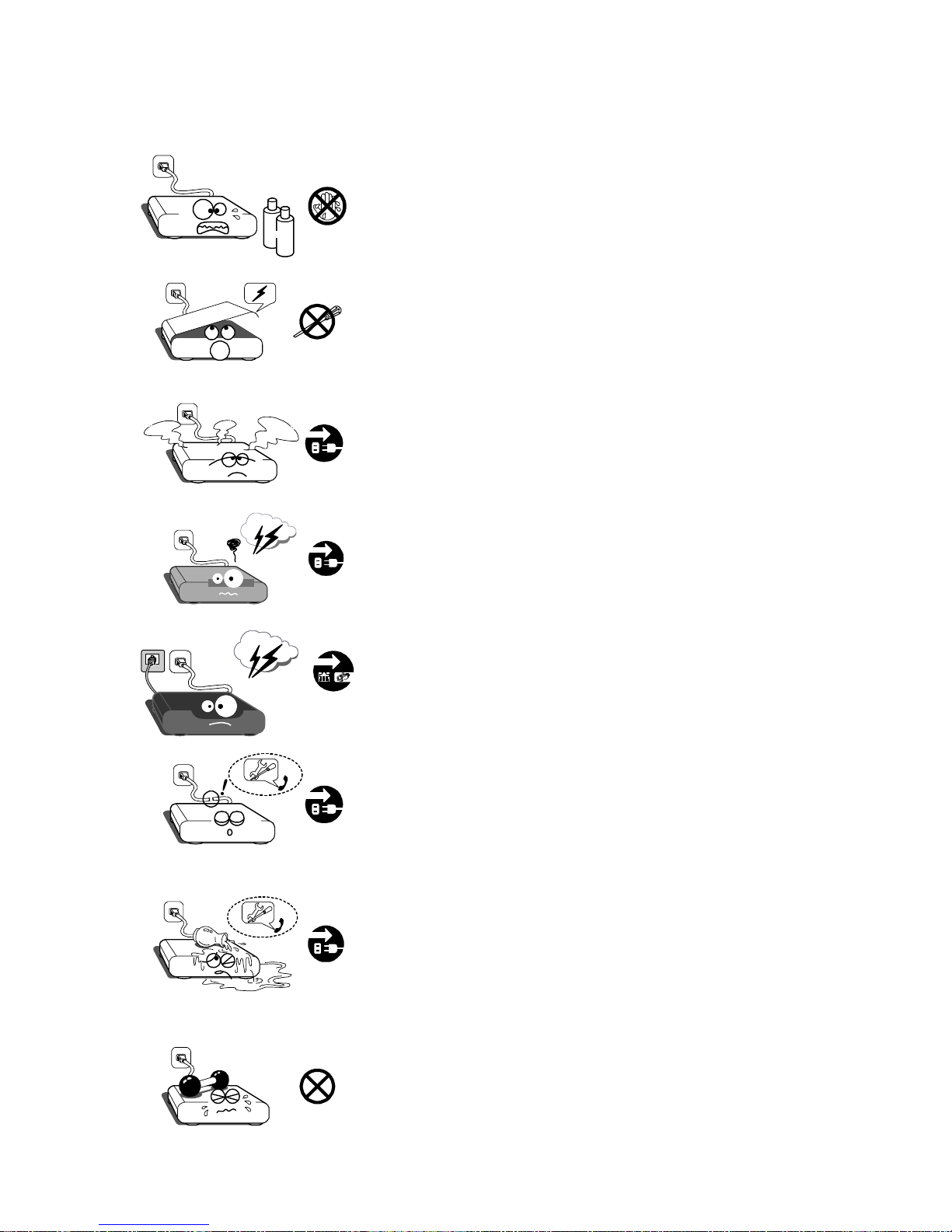
Alcohol
Unplug this device before cleaning. Use a soft cloth
dampened with water or a mild detergent; do not
use cleaners which may contain flammable
substances, like alcohol.
To avoid the risk of electric shock, do not perform
any servicing other than that described in this
manual, unless you are qualified to do so.
If a device malfunction occurs, or if you see smoke,
hear abnormal sounds, or detect a burning smell,
stop using the device immediately, and disconnect
the power cord from the electrical outlet.
Unplug this device when installing audio/video
cords.
Unplug this device during lightning storms.
Unplug the Ethernet cable during lightning storms.
z
z
Unplug this device when unused for a long period of
time. Do not use if the power cord is damaged.
Contact a trained service technician.
Protect the device from water during storage,
transport, and operation. Do not place objects filled
with liquids, such as vases, on top of the device. If
liquid has been spilled, unplug the device
immediately, and contact a trained service
technician.
Do not place heavy objects on top of the device.
Page 8
Important Safety Instructions
34
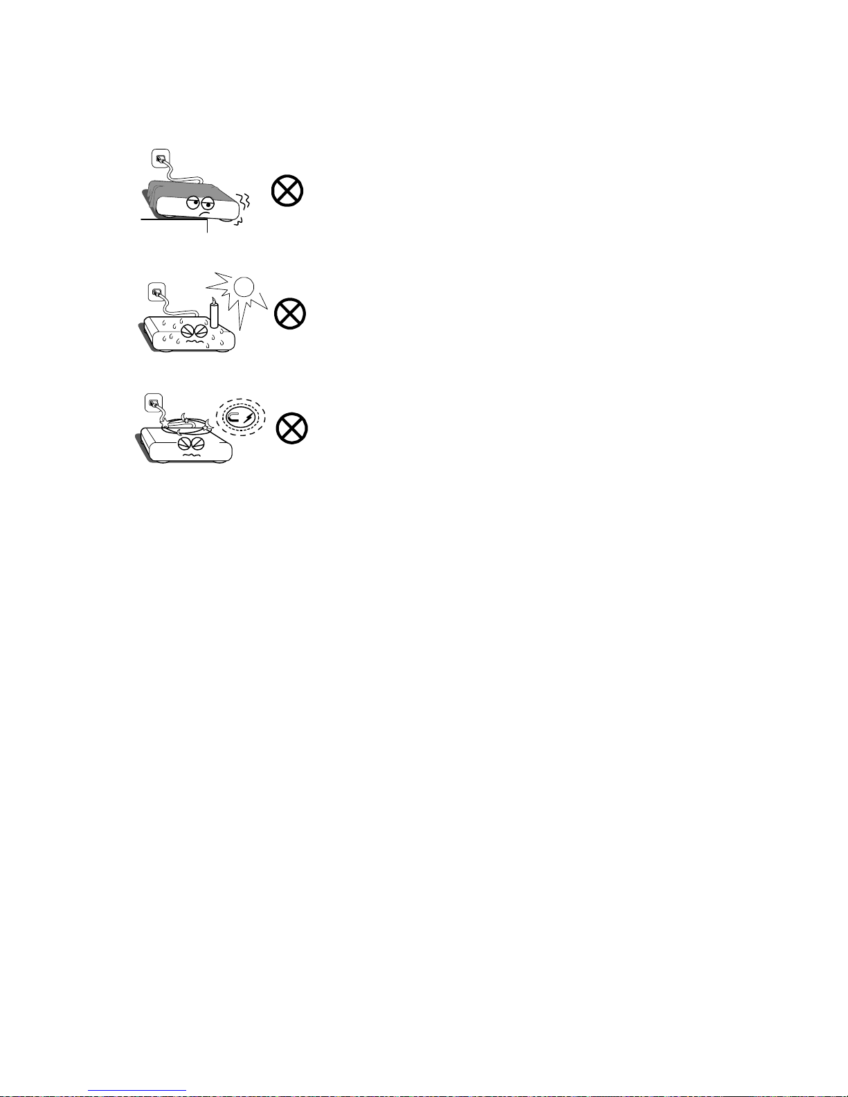
Place the device on a flat, solid surface; leave at
least 2.5cm (1 inch) space around the device to
ensure adequate ventilation. Do not block any
ventilation openings.
Do not install near heat sources, such as radiators,
heat registers, stoves, or other heat producing
devices (including amplifiers ). Protect from light ni ng,
rain, and direct sunlight.
&
Keep this device away from strong magnetic and
electrical fields.
Page 9

1 MC1088H Overview
35
1MC1088H Over view
Thank you for choosing the UTStarcom Media Console 1088H (MC1088H).
Please read this user guide carefully prior to use, and keep it for future
reference.
The MC1088H is a CATV/IPTV dual mode set top box (STB), that provides
cable TV (CATV) and IPTV service, as well as high speed Internet access.
UTStarcom RollingStream IPTV delivers services such as live TV, TimeShift-TV, TV on Demand (TVoD), Video on Demand (VOD), and other
value-added services over broadband networks.
Product View
Figure 1 shows the appearance of the MC1088H.
Figure 1 Media Console 1088H
Features
Supports traditional CATV service
Supports the following IPTV services:
- Live TV
- TV on Demand
- Time-Shift-TV
- Video on Demand
Supports value-added services such as interactive messaging
User-friendly Electronic Program Guide (EPG)
IR remote control
Page 10

1 MC1088H Overview
36
Network Connection
Figure 2 illustrates how the Media Console 1088H connects to the service
provider network.
Figure 2 Media Console 1088H Connected to Network
The MC1088H receives multimedia streaming data from the service
provider network and decodes the data to provide a range of services on
TV.
Page 11

2 Device Introduction
37
2Device Introduction
This chapter describes the MC1088H front and rear panels, and the remote
control.
Front Panel Description
Figure 3 shows the MC1088H front view. Push and release the
cover on the right side of the faceplate to access the USB
interfaces and smart card slot. Table 1 describes the numbered
items in Figure 4.
Figure 3 MC1088H Front View
Figure 4 MC1088H Front View with Cover Open
Table 1 MC1088H LED and Button Descriptions
Items Item Label Description
1 [Power button]
Push to select on or standby, indicated by the LED:
·
Green – on
·Red – standby
2 IR IR sensor. Receives signals from the remote control.
3
[Cursor
buttons]
Used to navigate the Electronic Program Guide.
Same functions as the remote control navigation
buttons.
4 Menu
Button used to display the Electronic Program Guide
menu page. Same function as the remote control
Menu butt on.
Page 12

2 Device Introduction
38
Items Item Label Description
5 Select
Button used to confirm a selection. Same function as
the remote control OK button.
6 Cancel
Button used to return to the previous screen. Same
function as the remote control BACK button.
7 USB
Two Universal Serial Bus interfaces used to connect
USB peripherals, such as a USB mouse and
keyboard.
8 [Cover Panel] Cover that protects the interfaces.
9 Smart Card Stores user information
10 Status On when the MC1088H is powered on.
11 IR
Flashes when the built-in IR sensor receives signals
from the remote control.
12 Ext IR
Flashes when the optional external IR sensor receives
signals from the remote control.
13 CATV On when CATV is in service
Rear Panel Description
Figure 5 MC1088H Rear View
Table 2 MC1088H Rear Interface Descriptions
Items Interface Description
1 RF IN Cable TV signal input
2 POWER IN Power supply input
3 Ext IR
Used to connect an external IR sensor. When an
external IR sensor is connected, the built-in IR
sensor is disabled.
Page 13

2 Device Introduction
39
Items Interface Description
4 S/PDIF
Sony/Philips Digital Interface Format compliant
digital audio output
5 S-VIDEO S-Video output
6
VIDEO OUTPUT
CVBS
Composite video output
7
VIDEO OUTPUT
Y, Pb, and Pr
YPbPr component analog video output
8
AUDIO OUTPUT
L and R
Analog audio output connector (L: left channel; R:
right channel)
9 LAN2 and LAN1 PC or home network Ethernet interface
10 WAN Connects to service provider network
Page 14

2 Device Introduction
40
Remote Control
Figure 6 MC1088H Remote Control
Table 3 MC1088H Remote Control Descriptions
Items Button Description
1 MUTE Use to turn the sound on/off
2 POWER Use to select on/standby
3
Number Buttons
(0-9)
Use to enter numbers/letters and switch channels
4 AUDIO Use to select left channel, right channel, or stereo.
Page 15

2 Device Introduction
41
Items Button Description
5
CH (CHANNEL) +
-
Use to select channels on the Media Console.
6 VOLUME Use to adjust volume on the Media Console.
7/8 PAGE + - Use to view next/previous page.
9 Menu
Use to go to the Electronic Program Guide main
page.
10 BACK Use to return to the previous page.
11
Navigation
Buttons
Use the arrow keys to navigate the Electronic
Program Guide and press OK to confirm a
selection.
12 INFO
Use to view the current program related
information.
13 Switch
Use to switch between the current program and the
previous program.
14
Playback control
buttons
Press
to play/pause-resume, to stop, to
fast-forward
to fast-reverse
15 Color buttons
Provide shortcut access to different services.
Please refer to the instructions on the screen for
details.
Page 16

3 Hardware Installation
42
3Hardwar e Install ation
This chapter describes how to connect the MC1088H cables. Before
connecting, be sure to:
Turn off the power on all devices to be connected
Read these instructions
Installation Preparation
Check the MC1088H package for the following items:
One Media Console 1088H
One audio/video cable (yellow: video, white: left channel, red: right
channel)
One Ethernet cable
One external IR receiver (optional)
One power adaptor
One remote control
Two AAA Batteries
If any of the items is missing, please contact your service provider.
Page 17

3 Hardware Installation
43
Connecting Audio/Video Cables
NOTE: CONNECT THE AUDIO/VIDEO CABL E S TO THE
CORRESPONDINGLY COLORED CONNECTORS.
Composite Video / CVBS (Composite Video Baseband Signal)
with Analog Audio
For a television with a CVBS connector, you can use the option shown in
Figure 7.
Figure 7 Composite Video (CVBS) with Analog Audio
Page 18

3 Hardware Installation
44
YPbPr Video with Analog Audio
For a television with YPbPr video connectors, it is recommended to use the
option shown in Figure 8.
YPbPr video offers High Definition Television
(HDTV).
Figure 8 YPbPr and Analog Audio
Page 19

3 Hardware Installation
45
S-Video and Analog Audio
For a television with an S-Video connector, you can use the option shown
in Figure 9.
S-video offers a higher level of standard definition video
quality than CVBS video.
Figure 9 S-Video and Analog Audio
Connecting Network Cable
Use the RJ45 Ethernet cable to connect the WAN connector of the Media
Console (Figure 10 to an Ethernet port on a device connected to your
service provider’s network.
Figure 10 Network Connection
Page 20

3 Hardware Installation
46
Connecting CATV Cable
To watch traditional cable TV, plug the CATV cable into the Media Console
RF IN connector, as shown on the left side of Figure 11.
Optional External IR Sensor
To use the remote control with an external IR sensor, plug the external IR
sensor USB cable into the Media Console Ext IR connector.
Figure 11 CATV and Optional IR Sensor Connections
Page 21

3 Hardware Installation
47
Connecting Power Adapter
Plug the DC power cable into the MC1088H POWER IN connector. Then
plug the power adapter into an AC power outlet. If possible, use an outlet
that is not controlled by a light switch.
Figure 12 Power Connection
To safely disconnect the Media Console, unplug the power adapter from
the power outlet first.
Page 22

4 Media Console Initial Setup
48
4Media C onsole I nitial Setup
After the Media Console is properly connected, do the following initial setup:
1 Insert the AAA batteries into the remote control.
2 Connect the Media Console (See the “Hardware Installation” section).
3 Check that the power adapter connections are secure and correct.
4 Turn on the Media Console and TV set.
5 Set the TV to the proper A/V mode.
6 Enter Domain Name, User Name, and Password.
a After powering on the Media Console, the following screen will
display. Use the remote control to enter the domain name
supplied by your service provider.
To enter domain name:
- Use the navigation buttons to highlight a letter, number, or
symbol on the left of the screen. Press OK on the remote control
to accept the selection.
- To delete a previously entered character, navigate to the
<Delete> key on the keyboard using the remote control arrow
keys and press OK.
b After entering the domain name, navigate to <OK> on the screen
and then press OK on the remote control.
c The system will validate the domain name. If validation fails, you
will be asked to re-enter the domain name.
Page 23

4 Media Console Initial Setup
49
If the validation is successful, the following User Authentication screen
will display. Use the remote control to enter the User Name and
Password supplied by your service provider.
To enter the User Name and Password:
- Enter your User Name, and then press R to move to the
Password field.
- Enter your Password.
- To delete or correct an entry, use the BACK button on the
remote control.
- To clear the input, navigate to the <Reset> key on the screen
and then press OK on the remote control.
d When finished entering the User Name and Password, navigate
to the <Register> key and press OK on the remote control.
A logon authorization page will display showing the network
initialization information, software downloading message, and logon
process messages.
If logon is successful, the Media Console will reboot automatically and
the Electronic Program Guide main page will display. If logon fails, a
failure page showing “Authentication Failed” will display. The Media
Console will then reboot automatically and display the sign-in page. If
login continues to fail, contact your service provider.
Page 24

5 Specifications
50
5Specifications
Operating temperature: 0 to 45° C
Operating humidity: 5 to 90% (non-condensing)
Storage temperature: -20 to 70° C
Environment
Requirements
Storage humidity: 0 to 98%(non-condensing)
Power Adapter
Requirements
Input voltage range: 90VAC to 260VAC
Output voltage: 12VDC
Powe r Consum ption
The maximum power consumption is less than 15W
Video
PAL/NTSC
Remote Control
Effective distance is up to 8m, angle ±30°
Dimensions
24cm (W)× 36cm(L) × 7cm(H)
Weight
Less than 1000g(power adaptor not included)
Page 25

6 Troubleshooting
51
6Troubleshooting
Problem Causes Corrective Actions
Power adapter is not
connected correctly.
Ensure the power adapter is
connected correctly
Power outlet is controlled
by a light switch that is
not turned on.
Ensure the power adapter is
not plugged into an outlet
controlled by a light switch or
turn on the controlling light
switch.
No power
Power is not turned on.
Press power button on
Media Console.
TV is not turned on. Ensure the TV is turned on.
Video cable is not
properly connected
Ensure the video cable is
connected correctly. Refer to
the “Hardware Installation”
section for detail.
No picture
TV is not set up properly
Adjust TV input mode to A/V
or S-Video
Audio cable is not
properly connected
Ensure the audio cable is
connected correctly. Refer to
the “Hardware Installation”
section for detail.
No sound
Volume control is
adjusted to minimum, or
MUTE is pressed
Turn the volume up or check
that MUTE is not selected
using the Media Console
remote control. Also ensure
that the volume is set high
enough on the TV and that
the TV mute is not selected.
The batteries are not
inserted with the correct
polarity
Insert the batteries properly
The batteries are dead or
there are no batteries.
Insert new batteries
Remote control is too far
from the Media Console
Move the remote control into
the effective range
Remote control
does not work
Something is between
the remote and the Media
Console IR sensor..
Remove the obstacle
Page 26

http://www.utstar.com
http://www.utstar.com.cn
 Loading...