

Page 1

P
r
e
l
i
m
i
n
a
r
y
FlexPacket ATCA PP50 Packet Processor
User Manual
CC06786-11B
Continuous Computing, the Continuous Computing logo, Create | Deploy | Converge, Flex21,
FlexChassis, FlexCompute, FlexCore, FlexDSP, FlexPacket, FlexStore, FlexSwitch, Network ServiceReady Platform, Quick!Start, TAPA, Trillium, Trillium+plus, Trillium Digital Systems, Trillium On Board,
TAPA, and the Trillium logo are trademarks or registered trademarks of Continuous Computing
Corporation. Other names and brands may be claimed as the property of others.
This document is confidential and proprietary to Continuous Computing Corporation. No part of this
document may be reproduced, stored, or transmitted in any form by any means without the prior written
permission of Continuous Computing Corporation.
Information furnished herein by Continuous Computing Corporation, is believed to be accurate and
reliable. However, Continuous Computing Corporation assumes no liability for errors that may appear in
this document, or for liability otherwise arising from the application or use of any such information or for
any infringement of patents or other intellectual property rights owned by third parties, which may result
from such application or use. The products, their specifications, and the information appearing in this
document are subject to change without notice.
The information contained in this document is provided “as is” without any express representations on
warranties. In addition, Continuous Computing Corporation disclaims all statutory or implied
representations and warranties, including, without limitations, any warranty of merchantability, fitness for a
particular purpose, or non-infringement of third-party intellectual property rights.
To the extent this document contains information related to software products you have not licensed from
Continuous Computing Corporation, you may only apply or use such information to evaluate the future
licensing of those products from Continuous Computing Corporation. You should determine whether or not
the information contained herein relates to products licensed by you from Continuous Computing
Corporation prior to any application or use.
Contributors: Continuous Computing Development Team, Naveen D’cruz, Kevin MacDowell.
Printed in U.S.A.
Copyright 2011 by Continuous Computing Corporation. All rights reserved.
Page 2

This device complies with Part 15 of the FCC Rules. Operation is subject to the following two
conditions: (1) this device may not cause harmful interference, and (2) this device mus t accept
any interference received, including interference that may cause undesired operation.
The user manual or instruction manual for an intentional or unintentional radiator shall caution
the user that changes or modifications not expressly approved by the party responsible for
compliance could void the user's authority to operate the equipment. In cases where the manual is
provided only in a form other than paper, such as on a computer disk or over the Internet, the
information required by this section may be included in the manual in that alternative form,
provided the user can reasonably be expected to have the capability to access information in that
form.
NOTE: This equipment has been tested and found to comply with the limits for a Class B digital
device, pursuant to Part 15 of the FCC Rules. These limits are designed to provide reasonable
protection against harmful interference in a residential installation. This equipment generates,
uses and can radiate radio frequency energy and, if not installed and used in accordance with the
instructions, may cause harmful interference to radio communications. However, there is no
guarantee that interference will not occur in a parti cu lar installation. If this equipment does cause
harmful interference to radio or television reception, which can be determined by turning the
equipment off and on, the user is encouraged to try to correct the interference by one or more of
the following measures:
-- Reorient or relocate the receiving antenna.
-- Increase the separation between the equipment and receiver.
-- Connect the equipment into an outlet on a circuit different from that to which the receiver is
connected.
-- Consult the dealer or an experienced radio/TV technician for help.
Page 3

P
r
e
l
i
m
i
n
a
r
y
Contents
1 Introduction 19
1.1 Part Numbers and Options.......................................................................... 20
1.1.1 Part Numbers ................................................................................ 20
1.1.2 Basic Configurations ..................................................................... 21
1.1.3 RTM ............................................................................................... 21
1.1.4 Accessories ................................................................................... 21
1.2 Glossary ...................................................................................................... 22
1.3 Additional Documentation ........................................................................... 25
2 Technical Overview 27
2.1 Main Features ............................................................................................. 28
2.1.1 RMI Processor Subsystem ............................................................ 28
2.1.2 Ethernet Switch Module ................................................................ 28
2.1.3 RTM Interface ................................................................................ 28
2.2 Hardware Overview..................................................................................... 29
2.2.1 Front Panel Ports .......................................................................... 29
2.2.2 Backplane Interface ....................................................................... 29
2.2.3 Connectors .................................................................................... 30
2.2.3.1 Internal Connectors ....................................................... 30
2.2.3.2 External Connectors ..................................................... 30
2.2.3.3 ATCA Connectors ......................................................... 30
2.2.4 Graphical Overview ....................................................................... 31
2.2.5 RMI Processor CPU Subsystem ................................................... 33
2.2.5.1 PSRAM (Flight Recorder Memory) ............................... 34
2.2.6 Fabric and Base Switch Modules .................................................. 36
2.2.7 Optional TCAM Mezzanine ........................................................... 38
2.2.8 RTM interface ................................................................................ 38
Page 5
CC06786-11B
Confidential and Proprietary
Page 4

FlexPacket ATCA PP50 Packet Processor
P
r
e
l
i
m
i
n
a
r
y
2.2.9 Management Subsystem ............................................................... 40
2.2.10 Front Panel .................................................................................... 40
2.2.10.1 LEDs ............................................................................. 40
2.2.10.2 Handle Switch ............................................................... 42
2.2.10.3 Management Port ......................................................... 42
2.2.10.4 Console Port ................................................................. 42
2.2.10.5 10GBASE-X Port .......................................................... 42
2.2.11 Jumpers ......................................................................................... 43
2.2.11.1 Default Jumper Settings ............................................... 43
2.2.11.2 Force Power On Jumper: J116 ..................................... 44
2.2.11.3 Console Mux Bypass Jumpers: J112, J113 .................. 45
2.2.11.4 Spare Serial Config Jumper: J111 ................................ 45
2.2.11.5 Alt Boot Bank Select Jumpers: J117, J118 ................... 45
2.2.11.6 Reserved Jumpers ........................................................ 46
2.2.12 Power Design ................................................................................ 46
2.2.13 Mean Time Between Failures ........................................................ 46
2.3 Component Integration Overview................................................................ 47
2.3.1 Firmware ....................................................................................... 47
2.3.2 IPMI ............................................................................................... 48
2.3.3 IPMC ............................................................................................. 48
2.3.4 IPMC and XLR Software Domains ................................................ 49
2.3.5 XLR Watchdog Timers .................................................................. 49
2.3.6 XLR Software ................................................................................ 49
2.3.7 XLR and IPMC Messaging ............................................................ 51
2.3.8 Power Domains ............................................................................. 53
2.4 Specifications .............................................................................................. 55
2.4.1 CPU / Memory ............................................................................... 55
2.4.2 Input/Output ................................................................................... 55
2.4.3 Expansion Options ........................................................................ 55
2.4.4 Software ........................................................................................ 55
2.4.5 Mechanical & Environmental Compliance ..................................... 55
2.4.6 Fuses ............................................................................................. 56
2.4.7 Certifications .................................................................................. 56
2.4.7.1 Planned Certifications ................................................... 56
2.4.8 Power Consumption ...................................................................... 56
3 Board Installation 57
3.1 Precautions ................................................................................................. 58
3.1.1 Environmental Requirements ........................................................ 58
3.1.2 Heat Dissipation and Dust Prevention ........................................... 58
3.1.3 Electrostatic Prevention ................................................................. 58
3.1.4 Other Precautions ......................................................................... 59
3.2 Unpacking the PP50 ................................................................................... 60
3.2.1 Compact Flash .............................................................................. 60
Page 6
User Manual
Continuous Computing Corporation
Page 5

Contents
P
r
e
l
i
m
i
n
a
r
y
3.2.2 Board Identification ........................................................................ 61
3.2.2.1 Serial Number ............................................................... 61
3.2.2.2 MAC Address ................................................................ 62
3.2.2.3 Part Number ................................................................. 63
3.2.2.4 MAC Address Location ................................................. 63
3.2.2.5 IPMI Manufacturing Info ................................................ 63
3.3 Installing PP50s into the Chassis................................................................ 64
3.3.1 Where to Install the PP50 .............................................................. 64
3.3.2 Board Insertion .............................................................................. 65
3.3.3 Air Blocker Modules in Vacant Slots ............................................. 69
4 Board Access, Bootup, and Shutdown 71
4.1 Serial Console Access ................................................................................ 72
4.1.1 Connect to the Serial Console ....................................................... 72
4.1.2 How to Switch Between Serial Consoles (IPMC, XLRs) ............... 73
4.2 IPMC Telnet Access.................................................................................... 75
4.2.1 Setting eth0 IP Address Manually ................................................. 75
4.2.2 Setting eth0.4094 IP Address Manually ........................................ 75
4.2.3 Setting the DNS Manually ............................................................. 76
4.3 Console Access for Development ............................................................... 77
4.3.1 Development Adapter (Hydra) Cable ............................................ 77
4.4 Board Shutdown.......................................................................................... 79
4.4.1 Using the IPMI Command to Shutdown ........................................ 79
4.4.2 Using the Handle Latch to Shutdown ............................................ 79
4.5 Board Reset ................................................................................................ 80
4.5.1 IPMI Cold Reset Command ........................................................... 80
4.5.2 IPMC (CNode) Reboot .................................................................. 80
1
4ABAB
5 Using the XLR SDK 81
5.1 Installing RMI Source Code & Development Tools ..................................... 82
5.2 Installing Continuous Computing Software ................................................. 83
5.3 Build the Linux Kernel ................................................................................. 84
5.3.1 Apply Kernel Patches to the RMI SDK Kernel Source .................. 84
5.3.1.1 Example of Using the Patch ......................................... 84
5.3.2 Build the Patched Linux Kernel ..................................................... 84
5.4 Cross Compiling Linux Applications using the RMI SDK Crosscompiler .... 86
6 Booting the XLRs 87
6.1 XLR Boot Methods ...................................................................................... 88
6.1.1 Network Boot ................................................................................. 88
6.1.1.1 Boot Server setup ......................................................... 88
6.1.1.2 PP50 Setup ................................................................... 88
6.1.1.3 Network Boot Example ................................................. 89
6.1.2 XLR Bootloader Commands .......................................................... 90
Page 7
CC06786-11B
Confidential and Proprietary
Page 6

FlexPacket ATCA PP50 Packet Processor
P
r
e
l
i
m
i
n
a
r
y
6.1.3 Compact Flash Boot ...................................................................... 91
6.1.3.1 Formatting Compact Flash ........................................... 92
6.1.3.2 Booting from Compact Flash ........................................ 92
6.2 Automating XLR boot .................................................................................. 94
6.2.1 Continuous Computing Multiboot .................................................. 94
6.2.1.1 Key Values (KV) ........................................................... 94
6.2.1.2 KV Variable Syntax ....................................................... 95
6.2.1.3 Access to Multiple Boot Method ................................... 96
6.2.1.4 Boot Method Syntax ..................................................... 96
6.2.1.5 Specifying Boot file ....................................................... 97
6.2.1.6 Specifying Boot command ............................................ 97
6.2.1.7 Specifying Boot Arguments .......................................... 98
6.2.1.8 Watchdog Feature ........................................................ 98
6.2.1.9 Initializing Multiboot ...................................................... 99
6.2.1.10 Multiboot Example ...................................................... 101
6.2.2 Autobooting Using Environment Variables .................................. 101
6.3 XLR Utility ................................................................................................. 102
6.3.1 Installing Linux Utilities ................................................................ 102
6.3.1.1 RMI Linux .................................................................... 102
6.3.1.2 WR Linux .................................................................... 102
6.3.2 XLR Commands Available From the BootLoader ....................... 103
6.3.2.1 kv ................................................................................ 103
6.3.2.2 showboot .................................................................... 104
6.3.2.3 rollboot ........................................................................ 104
6.3.3 XLR Commands Available From Linux ....................................... 104
6.3.3.1 NTP client ................................................................... 104
6.3.3.2 kv ................................................................................ 104
6.3.3.3 showboot .................................................................... 104
6.3.3.4 rollboot ........................................................................ 105
6.3.3.5 ipmi_setwd .................................................................. 105
6.3.3.6 fswcmd ........................................................................ 105
6.3.3.7 upgrade ....................................................................... 106
6.3.3.8 bswcmd ....................................................................... 106
6.3.3.9 getcpuid ...................................................................... 106
6.3.3.10 net_config ................................................................... 107
6.3.3.11 ipmi_setwd .................................................................. 107
6.3.3.12 ux_diag ....................................................................... 108
7 Intelligent Platform Management Controller 109
7.1 FRU Support ............................................................................................. 110
7.1.1 FRU State .................................................................................... 110
7.1.2 FRU Hot swap Sensors ............................................................... 111
7.1.3 FRU Data .................................................................................... 111
7.1.3.1 Example of FRU Data using Pigeon Point ShMc ........ 111
7.2 Sensors ..................................................................................................... 114
7.3 Link Descriptors ........................................................................................ 118
Page 8
User Manual
Continuous Computing Corporation
Page 7

Contents
P
r
e
l
i
m
i
n
a
r
y
7.3.1 PP50 with 10G Fabric Link Descriptors (shelf manager) ............ 120
7.3.2 PP50 with 4*1G Fabric Link Descriptors (shelf manager) ........... 120
7.4 Key Value (KV) Database ......................................................................... 122
7.4.1 KV Keys ....................................................................................... 122
7.4.2 To List All Key Value Entries ....................................................... 132
7.5 IPMI and PICMG Commands.................................................................... 134
7.5.1 IPMI Device Global Commands .................................................. 135
7.5.2 BMC Watchdog Timer Commands .............................................. 135
7.5.3 Chassis Device Commands ........................................................ 135
7.5.4 Event Commands ........................................................................ 136
7.5.5 Sensor Device Commands .......................................................... 136
7.5.6 FRU Device Commands .............................................................. 138
7.5.7 SDR Device Commands ............................................................. 138
7.5.8 SEL Device Commands .............................................................. 138
7.5.9 ATCA (PICMG 3.0) Commands .................................................. 139
7.5.9.1 FRU Control Command .............................................. 140
7.5.10 OEM API Commands .................................................................. 141
7.5.10.1 Get Payload CPU-Reset ............................................. 141
7.5.10.2 Set Payload CPU-Reset ............................................. 143
7.5.10.3 Get Payload Active Flash Bank .................................. 143
7.5.10.4 Set Payload Active Flash Bank ................................... 144
7.5.10.5 Get Self Payload ID .................................................... 145
7.5.10.6 Get Payload ID for Watchdog Commands .................. 146
7.5.10.7 Set Payload ID for Watchdog Commands .................. 148
7.5.10.8 Get IPMC Key N ......................................................... 149
7.5.10.9 Get IPMC Key-Value .................................................. 150
7.5.10.10 Set IPMC Key-Value ................................................... 151
7.5.10.11 Get IPMC Key-Value Extended .................................. 153
7.5.10.12 Set IPMC Key-Value Extended ................................... 154
7.5.10.13 Sensor Thresholds and Hysteresis Overview ............. 155
7.5.11 IPMI Command Completion Codes ............................................. 158
7.6 Error Logging ............................................................................................ 160
7.7 Behavior of IPMI Resets ........................................................................... 161
7.7.1 IPMI Cold Reset .......................................................................... 161
7.7.2 IPMI Watchdog Reset ................................................................. 161
7.7.2.1 Linux Application Level ............................................... 161
7.7.2.2 Hardware Level ........................................................... 161
7.7.3 IPMI Firmware Upgrade Reset .................................................... 162
7.8 IPMC Command Line Interface................................................................. 163
7.8.1 bmc_watchdog ............................................................................ 164
7.8.2 commit ......................................................................................... 164
7.8.3 debuglevel ................................................................................... 165
7.8.4 getactivebank .............................................................................. 165
7.8.5 getresetstatus .............................................................................. 166
7.8.6 help .............................................................................................. 166
7.8.7 kv ................................................................................................. 167
1
4ABAB
Page 9
CC06786-11B
Confidential and Proprietary
Page 8

FlexPacket ATCA PP50 Packet Processor
P
r
e
l
i
m
i
n
a
r
y
7.8.8 listdev .......................................................................................... 168
7.8.9 listfwdev ....................................................................................... 168
7.8.10 listpay .......................................................................................... 168
7.8.11 localaddress ................................................................................ 169
7.8.12 quit ............................................................................................... 169
7.8.13 resetdev ....................................................................................... 169
7.8.14 restore ......................................................................................... 169
7.8.15 sel ................................................................................................ 170
7.8.16 sendcmd ...................................................................................... 170
7.8.17 setactivebank .............................................................................. 171
7.8.18 setresetstatus .............................................................................. 171
7.8.19 version ......................................................................................... 171
8 Network Configuration 173
8.1 Fabric Switch Models ................................................................................ 175
8.2 Fabric Switch Management....................................................................... 176
8.2.1 Managing the Fabric Switch with fswcmd ................................... 176
8.2.1.1 autopause ................................................................... 177
8.2.1.2 reload .......................................................................... 177
8.2.1.3 show stats ................................................................... 178
8.2.1.4 clear ............................................................................ 178
8.2.1.5 route ............................................................................ 178
8.2.1.6 set port ........................................................................ 178
8.2.1.7 enable/disable port ..................................................... 179
8.2.1.8 enable/disable port e-keying ....................................... 179
8.2.1.9 enable/disable ingress vlan ........................................ 180
8.2.1.10 enable/disable accept untagged port .......................... 180
8.2.1.11 set port default ............................................................ 180
8.2.1.12 add vlan ...................................................................... 180
8.2.1.13 del vlan ....................................................................... 181
8.2.1.14 show ........................................................................... 181
8.2.1.15 SFP Commands ......................................................... 181
8.2.1.16 show Commands ........................................................ 181
8.2.1.17 cfgreg .......................................................................... 182
8.2.1.18 dump ........................................................................... 182
8.2.1.19 show version ............................................................... 182
8.2.1.20 dump ........................................................................... 182
8.2.1.21 enable | disable mac-learning ..................................... 182
8.2.1.22 enable | disable flooding broadcast ............................ 182
8.2.1.23 high and low watermark range .................................... 183
8.2.1.24 enable | disable protocol-traps .................................... 183
8.2.1.25 show link ..................................................................... 183
8.2.1.26 MAC aging .................................................................. 184
8.2.2 fswcmd Start Up File ................................................................... 184
8.2.3 FIBM Mode .................................................................................. 185
8.2.3.1 Enabling FIBM Mode .................................................. 186
Page 10
User Manual
Continuous Computing Corporation
Page 9

Contents
P
r
e
l
i
m
i
n
a
r
y
8.3 Base Switch Management and Port Connectivity ..................................... 187
8.3.1 Default Behavior .......................................................................... 187
8.3.1.1 Broadcom Management Tag (BMT) ........................... 188
8.3.1.2 Register Initialization in u-boot .................................... 189
8.3.2 Configurable Behavior ................................................................. 191
8.3.3 Alternate bswitch Behavior .......................................................... 194
8.3.4 Configuration ............................................................................... 194
8.3.4.1 num_of_fakes: .......................................................... 194
8.3.4.2 vlan_method .............................................................. 194
8.3.5 Design Overview ......................................................................... 195
8.3.5.1 VLAN mode ............................................................... 196
8.3.5.2 BMT Mode ................................................................. 196
8.3.6 Key Value Database Syntax ........................................................ 197
8.3.7 Examples ..................................................................................... 197
8.3.7.1 VLAN method ............................................................ 197
8.3.7.2 Mask Method ............................................................ 198
8.3.8 Front Mode .................................................................................. 198
8.3.9 RTM Mode ................................................................................... 198
8.4 Ethernet Ports on the RTM ....................................................................... 199
8.5 Fabric and Base Switch Management....................................................... 199
8.6 CNode Base Switch (bswcmd) Command ................................................ 200
8.6.1 Binding bswcmd to the CNODE's IP ........................................... 200
8.6.2 bswcmd Usage Examples ........................................................... 200
8.6.2.1 Common bswcmd Commands .................................... 200
8.6.3 Fabric Switch ............................................................................... 202
8.7 Configuring XLR Network Interfaces using KV.......................................... 203
8.7.1 Configuring XLR Network Interfaces Example ............................ 204
1
4ABAB
9 Using Wind River Linux on the PP50 205
9.1 Overview ................................................................................................... 206
9.1.1 CCPU/WindRiver Release Compatibility ..................................... 206
9.1.2 Installation Requirements ............................................................ 207
9.1.2.1 For WindRiver PNE LE 2.0 ......................................... 207
9.2 Installing the Template and Patch............................................................. 208
9.2.1 Installation Steps for WindRiver PNE 2.0 .................................... 208
9.3 Building the Kernel and NFS..................................................................... 209
9.3.1 Installing the Boot Kernel and NFS ............................................. 217
9.3.2 Booting the Target Blade ............................................................. 217
9.4 Memory Map Setup................................................................................... 218
9.5 Linux Setup ............................................................................................... 218
9.6 Linux Command Line Options................................................................... 219
9.6.1 linux_cpu_mask=<cpu_mask> .................................................... 219
9.6.2 kseg0_start=<address> ............................................................... 219
9.6.3 kseg0_size=<size> ...................................................................... 219
9.6.4 kumem=<size@addr> ................................................................. 220
9.6.4.1 Examples of Using kumen .......................................... 220
Page 11
CC06786-11B
Confidential and Proprietary
Page 10

FlexPacket ATCA PP50 Packet Processor
P
r
e
l
i
m
i
n
a
r
y
9.6.5 kuseg_start_hi=<hi_address> ..................................................... 221
9.6.6 kuseg_start_lo=<lo_address> ..................................................... 221
9.6.7 kuseg_size_hi=<hi_size> ............................................................ 221
9.6.8 kuseg_size_lo=<lo_size> ............................................................ 221
9.6.9 app_sh_mem_sz=<hex_size> .................................................... 222
9.6.10 shared_core ................................................................................ 222
9.7 Linux Loader Applications ......................................................................... 223
9.7.1 userapp ....................................................................................... 223
9.7.1.1 load ............................................................................. 223
9.7.1.2 stop ............................................................................. 224
9.7.1.3 status .......................................................................... 224
9.7.1.4 showmem ................................................................... 224
9.7.1.5 shmem ........................................................................ 225
9.8 Building an RMIOS application ................................................................. 226
9.8.1 Building KSEG0 applications ....................................................... 226
9.8.2 Stop and Re-load support ........................................................... 226
10 Rear Transition Modules 227
10.1 Standard RTM ........................................................................................... 228
10.1.1 Standard RTM Features .............................................................. 228
10.1.2 Specifications and Features ........................................................ 228
10.1.2.1 General ....................................................................... 228
10.1.2.2 Mechanical .................................................................. 228
10.1.2.3 Power .......................................................................... 229
10.1.2.4 Management .............................................................. 229
10.2 COP50 RTM.............................................................................................. 230
10.2.1 COP50 Features ......................................................................... 230
10.2.2 Important COP50 Terms Definitions ........................................... 231
10.2.3 COP50 RTM Overview ................................................................ 232
10.2.3.1 Bypass protection ....................................................... 234
10.2.4 COP50 Specifications and Features ........................................... 234
10.2.4.1 General ....................................................................... 234
10.2.4.2 Mechanical .................................................................. 234
10.2.4.3 Power .......................................................................... 234
10.2.4.4 Management .............................................................. 235
10.2.4.5 Bypass protection ...................................................... 236
10.2.4.6 IPMC Firmware .......................................................... 236
10.2.5 Installation and Usage ................................................................. 236
10.2.5.1 Initial Installation ......................................................... 236
10.2.5.2 PP50 IPMC Bootup and the COP50 ........................... 237
10.2.5.3 RTM Insertion ............................................................. 238
10.2.5.4 Upgrading the COP50 RTM CPLD ............................. 238
10.2.5.5 RTM Removal ............................................................. 239
10.2.5.6 Auto-Arm versus Managed Re-Arming ....................... 239
10.2.5.7 Software Specifications .............................................. 239
10.2.5.8 COP50 Usage Example .............................................. 243
Page 12
User Manual
Continuous Computing Corporation
Page 11

Contents
P
r
e
l
i
m
i
n
a
r
y
11 Firmware Upgrades 245
11.1 CPLD Upgrade .......................................................................................... 245
11.1.1 CPLD Upgrade Examples ........................................................... 246
11.2 XLR bootloader Upgrade .......................................................................... 247
11.2.1 Get Image File ............................................................................. 247
11.2.1.1 Upgrade Boot Flash Via Network ............................... 247
11.2.1.2 Get Bootloader Image File from TFTP Server ............ 247
11.2.2 Loading Image Files .................................................................... 247
11.2.2.1 Ping-Pong Upgrade Method ....................................... 248
11.2.2.2 Factory Golden Upgrade Method ............................... 249
11.3 Upgrading the PP50 IPMC ........................................................................ 252
11.3.1 Upgrading Versions 2.3.x or Later to a Higher Version ............... 252
11.3.2 Upgrading Versions 2.2.x or Earlier to a Higher Version ............. 253
11.3.3 Showing, Switching, and Rebooting Boot Banks ........................ 255
11.4 Linux Bootloader Upgrade Tool ................................................................ 257
11.4.1 In WR Linux ................................................................................. 257
11.4.2 In RMI Linux ................................................................................ 258
11.5 XLR Fabric Switch Configuration Utility, Installation ................................. 259
1
4ABAB
12 Diagnostics and Troubleshooting 261
12.1 Overview ................................................................................................... 261
12.2 Running Diagnostic Tests from Raw CLI .................................................. 262
12.2.1 IPMC Raw CLI Diagnostic Commands ....................................... 262
12.2.2 XLR Raw CLI Diagnostic Commands ......................................... 263
12.3 Running Diagnostic Tests using KV Settings ............................................ 265
12.3.1 Running IPMC Diagnostic tests with KV settings ........................ 266
12.3.1.1 IPMC U-boot command for short/long POST tests ..... 266
12.3.1.2 IPMC Linux utility for POST/BIST tests ...................... 267
12.3.2 Running XLR Diagnostic Tests with KV settings ......................... 269
12.3.2.1 XLR Commands for Short/Long POST tests .............. 269
12.3.2.2 XLR RMI Linux Utility for POST/BIST Tests ............... 271
12.4 Indicating XLR’s POST/BIST Status Using LEDs ..................................... 275
12.5 Determining Board Build ........................................................................... 276
13 Product Repair and Returns 277
13.1 Customer Support ..................................................................................... 277
13.2 Warranty.................................................................................................... 277
13.2.1 RMA Procedure ........................................................................... 278
13.2.2 Non-Warranty Repairs ................................................................. 278
13.2.3 Shipping ...................................................................................... 278
13.2.4 Expedite Option for Repairs ........................................................ 278
14 Revision History 279
Page 2-13
CC06786-11B
Confidential and Proprietary
Page 12

FlexPacket ATCA PP50 Packet Processor
P
r
e
l
i
m
i
n
a
r
y
Page 2-14
User Manual
Continuous Computing Corporation
Page 13

P
r
e
l
i
m
i
n
a
r
y
Figures
Figure 2-1 PP50 Overview Photo .................................................................................... 27
Figure 2-2 Front Panel ..................................................................................................... 29
Figure 2-3 Overall Hardware Block Diagram. .................................................................. 31
Figure 2-4 Base and Fabric Connection Diagram. ........................................................... 32
Figure 2-5 RMI Processor CPU Subsystem .................................................................... 33
Figure 2-6 Switch Module ................................................................................................ 36
Figure 2-7 RTM interface in Chassis ............................................................................... 38
Figure 2-8 RTM Panel ...................................................................................................... 39
Figure 2-9 Front Panel LEDs ........................................................................................... 40
Figure 2-10 IPMC Overview ............................................................................................. 48
Figure 2-11 XLR Software Overview ............................................................................... 49
Figure 2-12 XLR and IPMC Messaging ........................................................................... 51
Figure 2-13 XLR and IPMC Boot Messaging ................................................................... 51
Figure 2-14 XLR and IPMC Telnet Messaging ................................................................ 52
Figure 2-15 XLR and IPMC IPMI Messaging ................................................................... 52
Figure 2-16 Virtual Switches ............................................................................................ 53
Figure 2-17 Power Domains, Startup ............................................................................... 54
Figure 3-1 ESD Wrist Strap ............................................................................................. 59
Figure 3-2 PP50 Unpacking ............................................................................................. 60
Figure 3-3 Serial Number Location .................................................................................. 61
Figure 3-4 Part Number Location ..................................................................................... 63
Figure 3-5 MAC Address Location ................................................................................... 63
Figure 3-6 5U Chassis Slots ............................................................................................ 64
Figure 3-7 12U Chassis Slots .......................................................................................... 64
Figure 3-8 Latch Handle .................................................................................................. 65
Figure 3-9 Opening the Latch Handle, Lever Release ..................................................... 66
Figure 3-10 Opened Latch Handle ................................................................................... 66
Figure 3-11 Installation - Locator Pins ............................................................................. 67
Figure 3-12 Installation - Board Insertion ......................................................................... 68
Page 15
CC06786-11B
Confidential and Proprietary
Page 14

FlexPacket ATCA PP50 Packet Processor
P
r
e
l
i
m
i
n
a
r
y
Figure 3-13 PP50 Installation - Board Insertion, Latch Closure ....................................... 69
Figure 4-1 Serial Console Cable ...................................................................................... 72
Figure 4-2 Connecting Computer to the Serial Console .................................................. 72
Figure 4-3 Hydra Cable for Multiple Simultaneous Connection ....................................... 77
Figure 4-4 Hydra Cable Jumpers (J111 and J113) .......................................................... 78
Figure 7-1 Get Payload Active Flash Bank Response Data .......................................... 144
Figure 7-2 Set Payload Active Flash Bank Request Data ............................................. 145
Figure 7-3 Set Payload Active Flash Bank Response Data .......................................... 145
Figure 8-1 Networking Components Diagram ............................................................... 174
Figure 8-2 Fulcrum In Band Management (FIBM) ......................................................... 185
Figure 8-3 PP50 Channel A and B Networks ................................................................ 188
Figure 8-4 Selective-mask bswitch Ingress Masks ........................................................ 190
Figure 8-5 BMT Mode eth0 egress ................................................................................ 191
Figure 8-6 BMT Mode eth1 egress ................................................................................ 192
Figure 8-7 BMT Mode eth1 ingress ............................................................................... 192
Figure 8-8 VLAN Mode eth0 egress .............................................................................. 193
Figure 8-9 VLAN Mode eth1 egress .............................................................................. 193
Figure 8-10 sysctl tree ................................................................................................... 195
Figure 9-1 WindRiver PNE LE 2.0 Files for CCPU Release 1.3 .................................... 207
Figure 9-2 Create a New Project ................................................................................... 209
Figure 9-3 Input the Name ............................................................................................. 210
Figure 9-4 Select Board ................................................................................................. 211
Figure 9-5 Static Analysis .............................................................................................. 212
Figure 9-6 Project Name ................................................................................................ 212
Figure 9-7 Linux Kernel Configuration ........................................................................... 213
Figure 9-8 Package Configuration ................................................................................. 214
Figure 9-9 Build WindRiver Linux Kernel ....................................................................... 215
Figure 9-10 Build WindRiver Linux NFS ........................................................................ 216
Figure 10-1 Standard RTM ............................................................................................ 228
Figure 10-2 COP50 RTM ............................................................................................... 230
Figure 10-3 COP50 Front View ..................................................................................... 232
Figure 10-4 RTM-COP50 Block Diagram ...................................................................... 233
Figure 10-5 cop50d daemon’s Internal State Model ...................................................... 240
Figure 11-1 Ping-Pong Upgrade Flow Diagram ............................................................. 249
Figure 11-2 Factory Golden Upgrade Flow Diagram ..................................................... 251
Figure 12-1 Diagnostic Tests Tree ................................................................................ 261
Page 16
User Manual
Continuous Computing Corporation
Page 15

P
r
e
l
i
m
i
n
a
r
y
Tables
Table 1-1 PP50 and Accessory Part Numbers ........................................................ 20
Table 1-2 Terms Used in this Document.................................................................. 22
Table 2-1 RMI XLR Family Configurations............................................................... 33
Table 2-2 Ethernet Switch Operating Modes ........................................................... 37
Table 2-3 Ethernet Switch Port Usage..................................................................... 37
Table 2-4 LED Description....................................................................................... 41
Table 2-5 PP50 Jumper Information ........................................................................ 43
Table 2-6 Console Debug Bypass ........................................................................... 45
Table 2-7 Debug Mode – Triple MUX Modes........................................................... 45
Table 2-8 Reserved Jumpers................................................................................... 46
Table 2-9 PP50 Major Firmware Categories............................................................ 47
Table 2-10 Fuse Specification.................................................................................... 56
Table 3-1 MAC Address Ports ................................................................................. 62
Table 6-1 Network Boot Options.............................................................................. 89
Table 7-1 PP50 Sensor List ................................................................................... 114
Table 7-2 Factory default settings of thresholds and hysteresis............................ 116
Table 7-3 Link Records on PP50 with 10G Fabric ................................................ 118
Table 7-4 Table 7-2: Link Records on PP50 with 4*1G Fabric ............................. 118
Table 7-5 Key Value Database .............................................................................. 122
Table 7-6 IPMI Device Global Commands............................................................. 135
Table 7-7 BMC Watchdog Timer Commands ........................................................ 135
Table 7-8 Chassis Device Commands................................................................... 135
Table 7-9 Event Commands .................................................................................. 136
Table 7-10 Sensor Device Commands .................................................................... 136
Table 7-11 FRU Device Commands ........................................................................ 138
Table 7-12 SDR Device Commands........................................................................ 138
Table 7-13 SEL Device Commands......................................................................... 138
Table 7-14 AdvancedTCA Commands .................................................................... 139
Table 7-15 OEM Request and Response CodeBytes.............................................. 141
Page 17
CC06786-11B
Confidential and Proprietary
Page 16

FlexPacket ATCA PP50 Packet Processor
P
r
e
l
i
m
i
n
a
r
y
Table 7-16 Get Payload CPU-Reset Request Data................................................. 141
Table 7-17 Get Payload CPU-Reset Response Data.............................................. 142
Table 7-18 Set Payload CPU-Reset Request Data. ................................................ 143
Table 7-19 Set Payload CPU-Reset Response Data .............................................. 143
Table 7-20 Get Payload Active Flash Bank Request Data ...................................... 144
Table 7-21 Get Self Payload ID Request Data ........................................................ 146
Table 7-22 Get Self Payload ID Response Data ..................................................... 146
Table 7-23 Get Payload ID for Watchdog Commands Request Data...................... 147
Table 7-24 Get Payload ID for Watchdog Commands Response Data................... 147
Table 7-25 Set Payload ID for Watchdog Commands Request Data...................... 148
Table 7-26 Set Payload ID for Watchdog Commands Response Data ................... 148
Table 7-27 Get IPMC Key N Request Data ............................................................. 149
Table 7-28 Get IPMC Key N Response Data .......................................................... 149
Table 7-29 Get IPMC Key-Value Request Data ...................................................... 150
Table 7-30 Get IPMC Key-Value Response Data.................................................... 150
Table 7-31 Set IPMC Key-Value Request Data....................................................... 151
Table 7-32 Set IPMC Key-Value Response Data .................................................... 152
Table 7-33 Get IPMC Key-Value Extended Request Data ...................................... 153
Table 7-34 Get IPMC Key-Value Extended Response Data ................................... 153
Table 7-35 Set IPMC Key-Value Extended Request Data....................................... 154
Table 7-36 Set IPMC Key-Value Extended Response Data.................................... 155
Table 7-37 Command: 50h Sub-command: 23h Request data ............................ 156
Table 7-38 Command: 50h Sub-command: 23h Response data............................. 156
Table 7-39 Command: 50h Sub-command: 24h Request data ............................... 157
Table 7-40 Command: 50h Sub-command: 24h Response data............................. 157
Table 7-41 Command: 50h Sub-command: 25h Request data ............................... 157
Table 7-1 IPMI Command Completion Codes ....................................................... 158
Table 7-42 Command: 50h Sub-command: 25h Response data............................. 158
Table 8-1 Virtual Broadcast Domains .................................................................... 187
Table 8-2 VLAN assignment to ingress packets.................................................... 189
Table 8-3 Selective-mask bswitch Ingress Masks ................................................. 189
Table 8-4 cnswmode Values.................................................................................. 194
Table 8-5 BMT mode Flood Ports.......................................................................... 196
Table 8-6 BMT mode Flood Ports.......................................................................... 196
Table 8-7 XLR Ethernet ports and their corresponding key values ....................... 203
Table 9-1 CCPU/WindRiver Release Compatibility ............................................... 206
Table 9-2 Boot Target Blade Network Configuration ............................................. 217
Table 12-1 IPMC Raw CLI Diagnostic (Hardware) Tests ........................................ 262
Table 12-2 XLR Raw CLI Diagnostic (Hardware) Tests .......................................... 264
Table 12-3 POST/BIST KV Keys ............................................................................. 265
Table 12-4 xx_bootmode Settings (xx: cn, s0, s1)................................................... 265
Table 12-5 Diagnostic types and test mask string assignment................................ 266
Table 12-6 kv_diag Usage and Options................................................................... 269
Table 12-7 XLR Diagnostic Tests ............................................................................ 272
Table 12-8 Determining Board Build by Revision Number ...................................... 276
Table 14-1 User Manual Revision History ............................................................... 279
Page 18
User Manual
Continuous Computing Corporation
Page 17

1
P
r
e
l
i
m
i
n
a
r
y
1Introduction
This manual provides instructions for installing and using Continuous Computing’s
FlexPacket PP50 (PP50) high-performance packet processing blade.
The PP50 provides deep-packet inspection capabilities that support advanced content-aware routing and security functions required by multi-service IP networks.
The blade is for next-generation infrastructure applications, including IPTV, radio
network controllers (RNC), security gateways, session border controllers, WiMAX
base station aggregation, and wireless xGSNs.
The PP50 includes one or two discrete multi-core MIPS64 packet processors. Each
processor provides 8 multi-threaded cores and contains a built-in security coprocessor capable of handling up to 10Gbps of bulk encryption/decryption (20Gbps per
blade).
Each processor with up to 8Gb of memory (16Gb per blade), as well as access to a
TCAM and content-based processors via mezzanines. TCAM is especially important
for very high performance IPv6 routing platforms. For a list of orderable configurations, accessories and their part numbers please see Section1.1.4, "Accessories" for
more information.
The PP50 interconnects the processors, I/O, and backplane fabrics using a nonblocking 10 Gigabit Ethernet (10GbE) switch. Each XLR processor has two 10GbE
ports to the switch, providing full duplex 10GbE capabilities. External I/O is supported over a dual redundant 10GbE backplane fabric (PICMG 3.1.9). Direct
connection to 10GbE and 1GbE ports on the front or rear supports specific cabling
requirements.
When used with Continuous Computing's FlexTCA systems and software, the PP50
provides the fastest path from application development to deployment revenue.
From IPTV to Wireless Core Networks, the PP50 can deploy a wide range of high
performance, scalable telecom applications.
Page 1-19
CC06786-11B
Confidential and Proprietary
Page 18

FlexPacket ATCA PP50 Packet Processor
P
r
e
l
i
m
i
n
a
r
y
1.1 Part Numbers and Options
1.1.1 Part Numbers
Part numbers below are the standard Continuous Computing part numbers. Customer-specific configurations may be assigned a unique part number.
Table 1-1: PP50 and Accessory Part Numbers
Description Part #
PP50 Boards
PP50, baseboard, dual 1GHz XLR732, four 1-GB 667 MHz memory 0-11126
PP50, baseboard, dual 1GHz XLR732, four 2-GB 667MHz memory 0-11127
Adapter Cable for Development
DB9 to micro-DB9 adapter cable used for development (6 feet). See
Section4.1, "Serial Console Access" for details.
PP50 Rear Transition Module
RTM, Ten 1GbE and two 10GbE (SFP/SFP+ cages only, excludes
modules). Only compatible with PP50
SFP/SFP+ Modules (for both FM40 and PP50)
Optical 10GbE 850nm SFP+ SR transceiver with “Limiting” receiver
output signal.
Optical 1GbE/2GbE, SFP-SX, 850nm, 550m reach, Ethernet/FC 5-02515
Copper SFP, 1000Base-T 5-02673
1.25/1.0625Gbps SFP 1310nm Fp Transceiver, Hot Pluggable 5-02714
10G SFP+ 1310nm Limiting, Hot Pluggable 5-02784
PP50 TCAM Mezzanines
PP50, 36 Mbit TCAM mezzanine 0-11760
PP50, 72 Mbit TCAM mezzanine 0-11761
5-02138
0-11024
5-02491
Page 1-20
User Manual
Continuous Computing Corporation
Page 19

P
r
e
l
i
m
1.1.2 Basic Configurations
The PP50 is shipped in the following configurations.
•2G per XLR
• 4G per XLR
• 8G per XLR
All use 667MHz DRAM.
1.1.3 RTM
One RTM works for all configurations. It supports two 10GbE and ten 1GbE ports.
It does not include SFP or SFP+ modules as standard.
1.1.4 Accessories
An optional TCAM mezzanine may be factory installed. Two sizes are offered:
Introduction
i
n
a
r
y
1
4ABAB
•36Mbit
•72Mbit
SFP or SFP+ modules can be ordered as required and they will be pre-integrated
Special serial cables (hydra cables) used for development are also available as a separate line item. See Section4.3.1, "Development Adapter (Hydra) Cable" for more
information about the cables.
Page 1-21
CC06786-11B
Confidential and Proprietary
Page 20

FlexPacket ATCA PP50 Packet Processor
P
r
e
l
i
m
i
n
a
r
y
1.2 Glossary
The following table lists definitions for acronyms used in this document.
Table 1-2: Terms Used in this Document
Term Definition
SHMC A software package for acting as a Shelf Manager
10GbE Ten Gigabit Ethernet
1GbE One Gigabit Ethernet
BSWITCH Base Switch
CNODE The PPC 405+FPGA+FLASH+switch with whatever software
packages are running on it
CPLD Complex Programmable Logic Device
DDR2 Double Data Rate 2 (memory interface)
DHCP Dynamic Host Configuration Protocol
DIMM Dual In-Line Memory Module
FIFO First In First Out
FSWITCH Fabric Switch
I2C, IIC or I2CInter-IC Bus
IMS IP Multimedia Subsystem
IPMB Intelligent Platform Management Bus
IPMC Intelligent Platform Management Controller
IPMI Intelligent Platform Management Interface
JTAG Joint Test Action Group
NSE Network Search Engine
NFS Network File System
QDR Quad Data Rate
RAM Random Access Memory
RMCP Remote Management Control Protocol
ROM Read Only Memory
RTM Rear Transition Module
SCL I2C Bus Serial Clock
Page 1-22
User Manual
Continuous Computing Corporation
Page 21

P
r
e
l
i
m
i
n
a
Table 1-2: Terms Used in this Document
Introduction
r
y
1
Term Definition
TCA Telecommunications Computing Architecture
TCAM Ternary Content Addressable Memory
TFTP Trivial File Transfer Protocol
UART Universal Asynchronous Receiver Transmitter
VFAT Linux file system that is compatible with Windows FAT
XLR RMI’s multi-core CPU
4ABAB
Page 1-23
CC06786-11B
Confidential and Proprietary
Page 22

FlexPacket ATCA PP50 Packet Processor
P
r
e
l
i
m
i
n
a
r
y
Notations
This table displays the notations used in this document:
Notation Explanation Examples
Arial Titles 1.1 Title
Book Antiqua Body text This is body text.
Bold Highlights information Loose coupling, tight coupling,
upper layer interface
Italics Document names,
emphasis
Command line input and output, and code is indicated by Courier New type and a
blue background as shown below.
PP50-1 $ iobus
IOBus Devices:
BaseAddr Size(KB) ChipSel Device
=============================================================================
0xbc000000 16384 0 cfiflash_0
Also note this document uses PDF page numbering compared to traditional number
schemes.
FlexPacket ATCA PP50 Packet
Processor
This must be installed.
Page 1-24
User Manual
Continuous Computing Corporation
Page 23

P
r
e
l
i
m
i
n
1.3 Additional Documentation
a
Introduction
r
y
1
This manual assumes you are familiar with the following documentation from RMI.
• RMI SDK Software Developer's Guide (referred to as “the RMI SDK Guide” in
this document)
• XLR Processor Family Programming Reference Manual
• TCAM User Manual (PN CC07478)
This document does not cover topics discussed in the above documents unless the
information is different for the PP50 platform.
You may also find it necessary to reference the MIPS 64 Architecture manuals, available for download from www.mips.org.
Finally, this manual assumes basic familiarity with setting up DHCP, TFTP, and
NFS servers, building Linux kernels, installing RPMs and tarballs, and using crosscompile tool chains.
4ABAB
Page 1-25
CC06786-11B
Confidential and Proprietary
Page 24

FlexPacket ATCA PP50 Packet Processor
P
r
e
l
i
m
i
n
a
r
y
Page 1-26
User Manual
Continuous Computing Corporation
Page 25
2
P
r
e
l
i
m
i
n
a
r
y
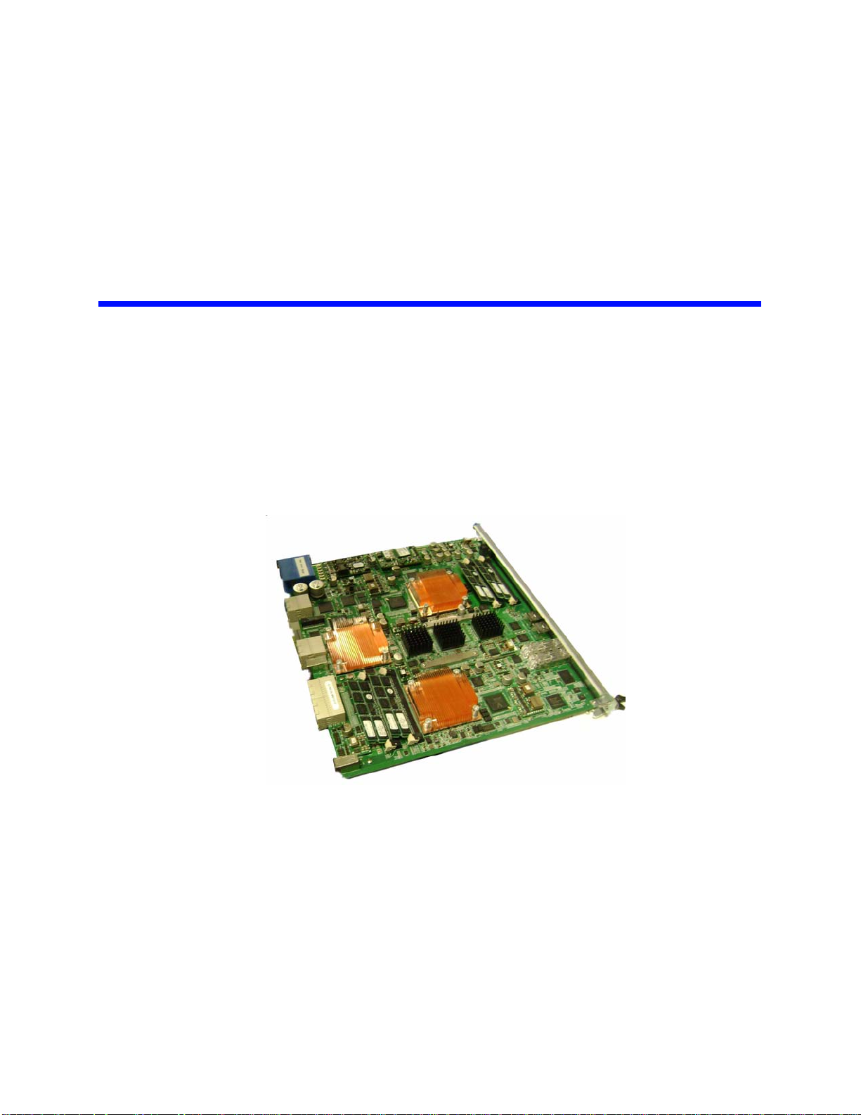
2Technical Overview
This chapter describes PP50 main features and gives an overview of the hardware
and software.
Figure 2-1: PP50 Overview Photo
Page 2-27
CC06786-11B
Confidential and Proprietary
Page 26

FlexPacket ATCA PP50 Packet Processor
P
r
e
l
i
m
i
n
a
r
y
2.1 Main Features
The PP50’s major subsystems are described in this section.
2.1.1 RMI Processor Subsystem
The RMI processor subsystem includes dual RMI XLR7xx BGA1605 CPU sites; a
PP50 can support any CPU in any of those families with the proper assembly
changes. See Section2.2.5, "RMI Processor CPU Subsystem" for processor subsystem details.
The RMI XLR processors support up to eight MIPS 64 bit RISC cores, each having 4
individual execution threads for a total of 32 execution threads.
See Table 2-1 "RMI XLR Family Configurations" for a reduced feature parts as list
for this processor family.
The PP50 supports reduced configurations based on these parts, but the default configuration is two XLR732s fully populated devices.
2.1.2 Ethernet Switch Module
FM2112/FM3112 (Fulcrum Microelectronics) Ethernet switch module, described in
detail in Section2.2.6, "Fabric and Base Switch Modules". The onboard fabric
Ethernet and base Ethernet switches facilitate connectivity. The fabric switch is a
layer 2 device that provides 10GbE connectivity for the CPUs as well as multiple
1GbE data paths. The base switch facilitates communication between the two XLR
CPUs, IPMC controller and two base interfaces.
2.1.3 RTM Interface
The PP50 supports a rear transition module (RTM) that includes a protected power
supply, a management interface to the IPMC, ten 1GbE interfaces and two 10GbE
interfaces.
Page 2-28
User Manual
Continuous Computing Corporation
Page 27
P
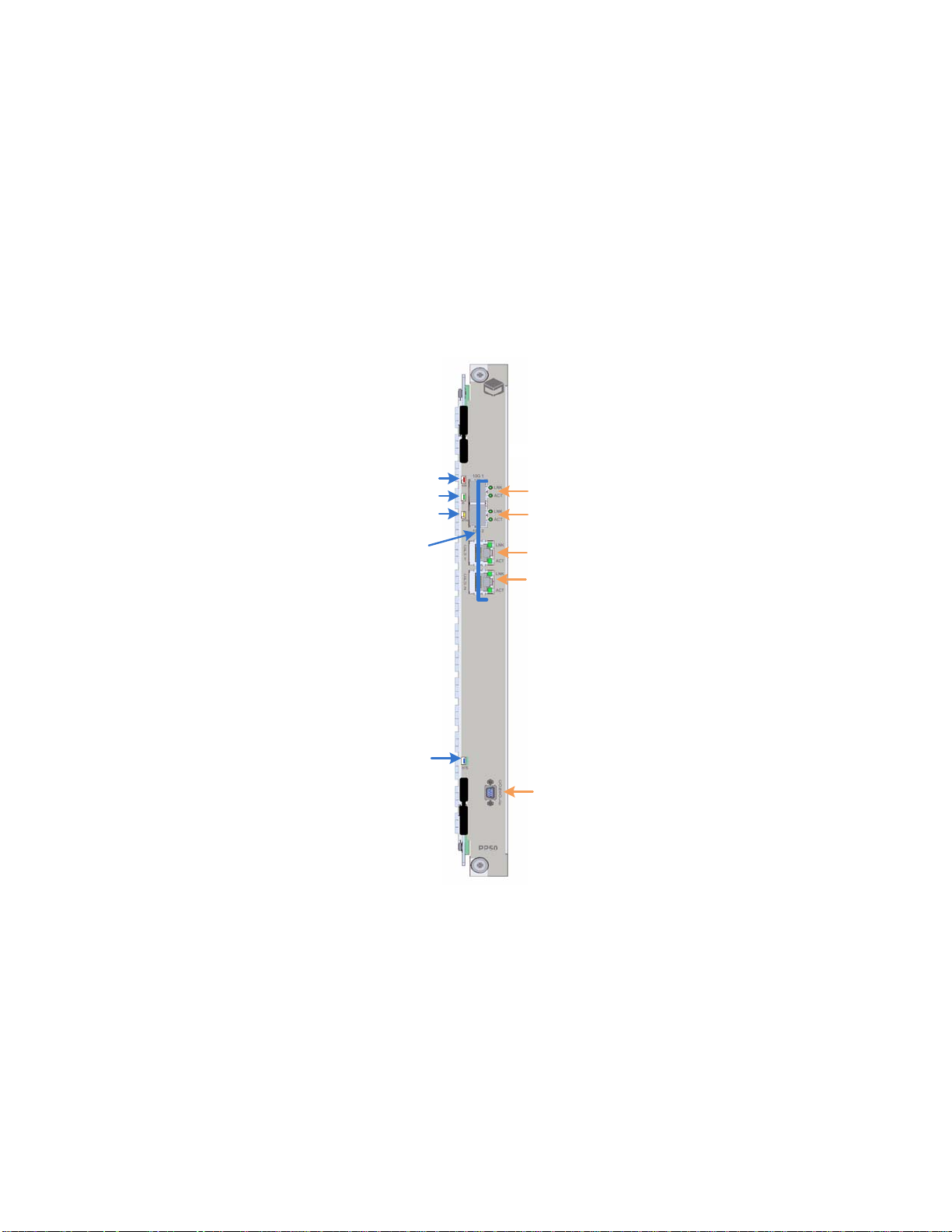
OOS
IS
ATTN
H/S
LNK and ACT
LEDs
Ports
10G 1
10G 2
CPU1
CPU2
CONSOLE
r
2.2 Hardware Overview
e
l
i
m
Technical Overview
i
n
a
r
y
1
2.2.1 Front Panel Ports
• 10GE.1: SFP+ port (IEEE 802.3 10GBASE-X)
• 10GE.2: SFP+ port (IEEE 802.3 10GBASE-X)
• CPU.1: RJ45 Connector to XLR 0
• CPU.2: RJ45 Connector to XLR 1
See Section2.2.10.1, "LEDs"for a description the LED indicators.
4ABAB
Figure 2-2: Front Panel
2.2.2 Backplane Interface
The PP50 is designed as a node board in an ATCA system. Its backplane interface is
compatible with the PICMG3.0 R2.0 specification.
Confidential and Proprietary
Page 2-29
CC06786-11B
Page 28

FlexPacket ATCA PP50 Packet Processor
P
r
e
l
i
m
i
n
a
r
y
2.2.3 Connectors
2.2.3.1 Internal Connectors
J15 - XLR CPU 2 Memory Channel AB Mini-DIMM Connector
J17 - XLR CPU 2 Memory Channel CD Mini-DIMM Connector
J18 - XLR CPU 1 Memory Channel AB Mini-DIMM Connector
J21 - XLR CPU 1 Memory Channel CD Mini-DIMM Connector
J52 - XLR CPU 2 CF card connector
J53 - XLR CPU 1 CF card connector
J54 - Extended JTAG connector from JTAG CPLD
J56 - JTAG connector for JTAG CPLD
J100 - Internal Mezzanine card connector
J101 - Internal Mezzanine card connector
J102 - JTAG connector for XLR CPU 1
J103 - JTAG connector for XLR CPU 2
J110 - JTAG connector for IPMC
2.2.3.2 External Connectors
J11 - Micro-DB9 Console Port
J104 - RJ45 Connector for XLR Module 1 (XLR0)
J105 - RJ45 Connector for XLR Module 2 (XLR1)
J109 - Two 10G SFP plus Ports connector
2.2.3.3 ATCA Connectors
P10 - ATCA Zone 1 Power Connector
J20 / J23 - ATCA Zone 2 connectors
J26 / J27 - ATCA Zone 3 connectors to RTM
Page 2-30
User Manual
Continuous Computing Corporation
Page 29
P
CF Flash
PSRAM
XLR732
)
DDRII DIMM
Four
GE MAC
Two 72bit
DRAM
interface
Two
10GE MAC
Local BUS
PCI- X BUS
Boot
Flas h
SRAM /
LA-1
HT BUS
CF Flash
PSRAM
XLR732
DDRII DIMM
Four
GE MAC
Two 72bit
DRAM
interface
L ocal BUS
Boot
Flash
SRAM /
LA-1
Two
10GE MAC
FM 2112
Core Switch
P1
P2
P24
Host Interfa ce
P9
P4
P6
P3
P8
P5
P7 P13
P11
P15
P21
P19
P23
P22
P20
P18
P17
P10
P16
P14
P12
RGMII
TCAM or QDRII
Mezzanine
HT Co- processor
Mezzanine
LA-1
LA-1
HT 8bit
PM8380
MUX
SPF+
Module
PM8380
MUX
XUAI
XUAI
MUX
or Resistor
RESISTOR
XUAI or
1000 BASE-X
XUAI or
1000 BASE-X
1000BASE-X
1000BASE-X
SPF+
Module
S
F
I
S
F
I
XUAI
XUAI
RTM
2
x
1
0
G
E
10 x 1GE
Fabric
10GE
(or 4x GE)
10GE
(or 4x GE)
Channel 2
Channel1
BCM5389
Base Switch
P
P
P
P
P
P
P
P
VSC7280
Dual
XGMII-XAUI PHY
XGMII
VSC7280
Dual
XGMII-XAUI PHY
XGMII
XUAI
XUAI
XUAI
XUAI
X
U
A
I
X
U
A
I
Base
Channel 1
Channel 2
BCM5482
1000 BASE-T
RJ45
RJ45
1000 BASE-T
1000 BASE-T
1000 BASE-X
1000 BASE-X
MII
I2C MDIO
I2C
MDIO
From IPMC
From IPMC
BCM5482
Dual PHY
BCM5482
Dual PHY
RGMII
BCM5482
Dual PHY
BCM5482
Dual PHY
AEL2005
BCM8706
16bit bus
405EZ
IPMC
Managed
by IPMC
IPMB A
IPMB B
FPGA
CRAM
FW2112
r
e
l
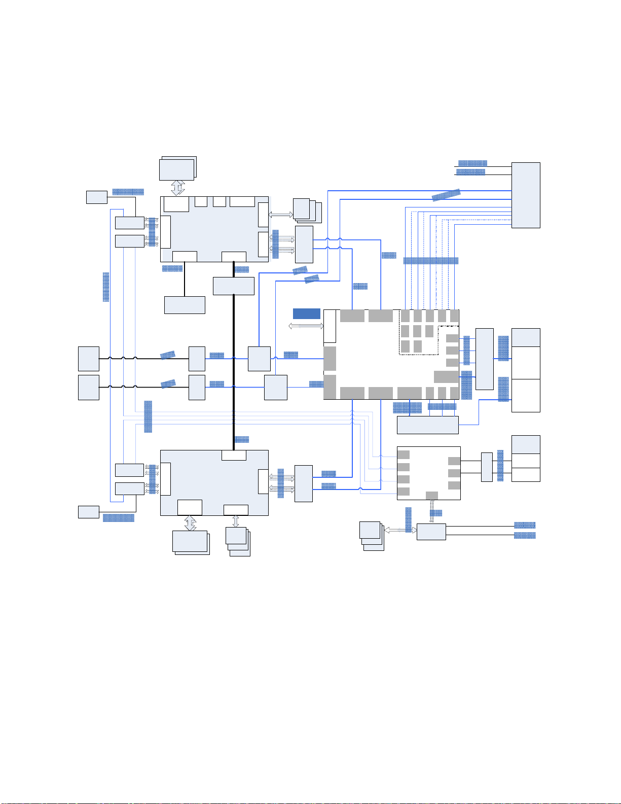
2.2.4 Graphical Overview
The following diagram provides a graphical overview the PP50’s hardware. The
zoom tool in your viewer may be used to magnify sections of interest.
i
m
Technical Overview
i
n
a
r
y
1
4ABAB
Page 2-31
Confidential and Proprietary
CC06786-11B
Figure 2-3: Overall Hardware Block Diagram.
Page 30
FlexPacket ATCA PP50 Packet Processor
P
r
e
l
i
m
i
n
a
r
y
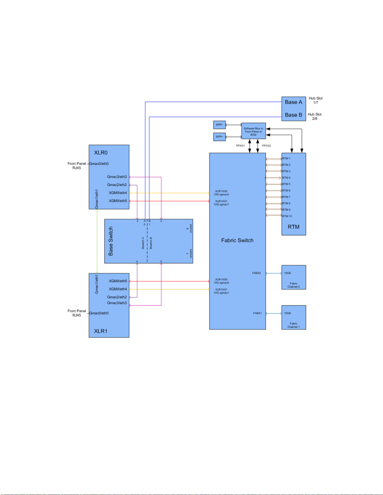
The diagram below shows connections between the PP50’s Base and Fabric
components.
Page 2-32
User Manual
Continuous Computing Corporation
Figure 2-4: Base and Fabric Connection Diagram.
Page 31

P
C ompact
Flash
CORE5
THREAD 17
THREAD 18
THREAD 19
THREAD 20
ICache
DCache
CORE6
THREAD 21
THREAD 22
THREAD 23
THREAD 24
ICache
DCache
CORE7
THREAD 25
THREAD 26
THREAD 27
THREAD 28
ICache
DCache
CORE8
THREAD 29
THREAD 30
THREAD 31
THREAD 32
ICache
DCache
To TCAM
Mezzanine
DDR2 DIMMDDR2 DIMM
RGMII A
RGMII B
RGMII C
RGMII D
GE MAC
GE MAC
GE MAC
GE MAC
SRAM /
LA-1
MEM AB MEM CD
10 GE
MAC
10 GE
MAC
XGMII A
XGMII B
Local
BUS
PCI-X
BUS
UART 1
UART 2
HT BUS
Boot
Flash
Console Serial Port
Command Serial Port
CPU sub- system
To Co- Processor
Mezzanine
VSC7280
Dual XGMII- XAUI
XAUI A XAUI B
I2C
CORE1
THREAD 1
THREAD 2
THREAD 3
THREAD 4
ICache
DCache
CORE2
THREAD 5
THREAD 6
THREAD 7
THREAD 8
ICache
DCache
CORE3
THREAD 9
THREAD 10
THREAD 11
THREAD 12
ICache
DCache
CORE4
THREAD 13
THREAD 14
THREAD 15
THREAD 16
ICache
DCache
RAZA XLR
8bit
8bit
PSRAM
10/100/
1000 base-T
1000BASE-X
1000BASE-X
1000BASE-X
To Front
Panel
To the other
CPU module
To Base
Switch
To Core Switch To Core Switch
To Base
Switch
C ontrol
CPLD
(XLR1 Only
)
BCM5482
Dual PHY
BCM5482
Dual PHY
r
e
l
i
m
i
n
a
r
y
2.2.5 RMI Processor CPU Subsystem
Technical Overview
1
4ABAB
Figure 2-5: RMI Processor CPU Subsystem
The PP50 uses two XLR7xx CPU sites. They are identical, except that the XLR at site
1 can access the co-processor mezzanine through the bus. The features of the CPU
subsystems are described below and shown in Figure 2-5 "RMI Processor CPU
Subsystem".
• RMI XLR7xx BGA1605 CPU sites; the PP50 can support any CPU in any of
those families with the proper assembly changes. They include the following
XLR Family of CPUs:
Table 2-1: RMI XLR Family Configurations
Part x32
XLR7xx 8 Cores, 32threads four 1GbE; two 10GbE
• Two 244 pin DDR2 Mini-DIMM sockets supporting standard 1.8V DDR2 MiniDIMMs
- One DIMM on memory channel A/B
- One DIMM on memory channel C/D
- Up to 800MHz DDR2 data rates
-Up to 4GB for each DIMM
Page 2-33
CC06786-11B
Confidential and Proprietary
Page 32

FlexPacket ATCA PP50 Packet Processor
P
r
e
l
i
m
i
n
a
r
y
•LA-1 Interface
- Connected to a mezzanine for TCAM add on options
• Four RGMII Gigabit Ethernet interfaces
- One interface is routed to the front panel as the management port
- Two interfaces are routed to the base switch
- One interface to the other XLR through serial interface
• Two XGMII 10 Gigabit Ethernet interfaces routed to the Fabric Ethernet switch
• Local Bus / Peripheral Interface
- 8/16/32 bit devices, 66MHz
- Two 32M bytes FLASH for boot firmware
- CompactFLASH socket for additional storage
-Two 8MB PSRAM
- Control Complex Programmable Logic Devices (CPLD)
•Two UART Ports
- Port 1 connected to CNODE for FlexConsole
- Port 2 connected to CNODE as a command channel
• Two I2C Ports
- Port 1 connected to two Mini-DIMM sockets for SPD
- Port 2 connected to a serial EEPROM
2.2.5.1 PSRAM (Flight Recorder Memory)
Each XLR subsystem on the PP50 includes PSRAM (pseudo-static DRAM). I is
sometimes called flight recorder memory because it is unique in that it is not cleared
or initialized during board resets/reboots, so it can be used to preserve critical state
or logs across such events.
After a power cycle, the contents of the PSRAM are undefined. It is recommended
that a checksum, CRC, or some other data integrity check be used on the data in the
PSRAM to ensure that random powerup contents are not interpreted as valid data.
Typical uses for the PSRAM are to store routing tables, call routing information,
transaction checkpoints, or log files. Having these tables available in memory can
enable much faster application startup after a board reset or watchdog timeout.
Because the PSRAM is separate from main memory, neither the bootloader nor the
Linux kernel will disturb its contents. Note, that the bootloader PSRAM diagnostic
copies the contents to a safe area before testing the PSRAM, then copies the data
back in.
To access the PSRAM from RMIOS, you can simply configure a pointer to point to
the PSRAM base address and access it directly.
Page 2-34
User Manual
Continuous Computing Corporation
Page 33

Technical Overview
P
r
e
l
i
m
i
n
a
r
y
To access the PSRAM from user level in Linux, use the mmap system call as shown
in the following code segment.
1
1. The start physical address and size of PSRAM on per XLR
PP50-1 $ iobus
IOBus Devices:
BaseAddr Size(KB) ChipSel Device
=============================================================================
0xbc000000 16384 0 cfiflash_0
0xb8000000 16384 3 cfiflash_1
0x19000000 16384 4 psram
0x1d000000 8192 6 pcmcia
0x1d840000 64 1 cpld
Note, for PSRAM, the start address is 0x19000000, the size is 16384KB.
2. Call system API "mmap" to transform physical address to virtual address. For
example:
volatile u16 *psram_mmap(u32 addr, u32 size)
{
int fd=-1;
volatile u16 *mAddr=NULL;
if (0 > (fd = open("/dev/mem", O_RDWR|O_SYNC)))
{
if(debug)
{
printf("Open /dev/mem error!\n");
}
return NULL;
}
if (MAP_FAILED == (mAddr = mmap(NULL, size, PROT_READ|PROT_WRITE, MAP_SHARED,
fd, addr)))
{
if(debug)
{
printf("mmap /dev/mem error!\n");
}
close(fd);
return NULL;
}
close(fd);
return mAddr;
}
4ABAB
3. Then you can access PSRAM as same as accessing system memory.
Confidential and Proprietary
Page 2-35
CC06786-11B
Page 34

FlexPacket ATCA PP50 Packet Processor
FM2112
Core Switch
P1
P2
P24
Host Interface
P9
P4
P6
P3 P8
P5 P7
P13
P11 P15
P21 P19
P23
P22
P20
P18
P17
P10
P16
P14
P12
To IPMC
PM8380
MUX
XAUI
To RTM
PM8380
MUX
XAUI
To RTM
To RAZA 1
To RAZA 1
To RAZA 2
To RAZA 2
XAUI XAUI XAUI
PHY PHY
SPF+
Module
SPF+
Module
SFI SFI
XAUI or
1000BASE-X
XAUI or
1000BASE-X
1000BASE-X
1000BASE-X
1000BASE-X
1000BASE-X
1000BASE-X
1000BASE-X
1000BASE-X
1000BASE-X
1000BASE-X
1000BASE-X
1000BASE-X
1000BASE-X
1000BASE-X
1000BASE-X
1000BASE-X
1000BASE-X
10 x 1 GE to RTM
MUX
MUX
10GE
(or 4 x 1GE)
10GE
(or 4 x 1GE)
To Fabric
Channel 2
Channel
1
XAUI
XAUI
XAUI
P
r
e
l
i
m
i
n
a
r
y
2.2.6 Fabric and Base Switch Modules
To Fabri
UI
Figure 2-6: Switch Module
The Ethernet data path is facilitated by a Fulcrum FM2112/FM3112 base and fabric
Ethernet switches. The FM2112/FM3112 contains eight 10GbE (4-lane) interfaces
and sixteen 1GbE (1-lane) interfaces. Any of the interfaces can be operated at two
speeds from two clocks, and the 4-lane ports can be operated as a single lane. The
clock input assignments for the Ethernet chip are:
• REFCLK_A (1-4) is 312.5MHz for 10GbE operation
Page 2-36
User Manual
Continuous Computing Corporation
• REFCLK_B (1-4) is 125MHz for 1GbE operation
Page 35

Technical Overview
P
r
e
l
i
m
i
n
a
r
y
Possible operating modes for the switch are listed in Table 2-2 "Ethernet Switch
Operating Modes".
1
Table 2-2: Ethernet Switch Operating Modes
Port Lanes Speed Mode
1 – 8 4 3.125GHz 10GbE
1 – 8 1 3.125GHz 2.5GbE
1 – 8 1 1.25GHz 1GbE
9 – 24 1 1.25GHz 1GbE
The fabric interface to the AdvancedTCA backplane can be configured for 10GbE or
four 1GbE operation. In 10GbE operation, Ports 7 and 5 are wired to all 4 ports in
channels 1 and 2. In four 1GbE operation, Ports 7 and 5 are put in 1GbE mode and
make up port [a] of the fabric interface. Switch ports [15 19 13] make up ports [b c d]
for channel 1, and likewise switch ports [21 11 9] make up ports [b c d] for Fabric
channel 2. The current allocation of the Fabric Ethernet ports are listed inTable 2-3
"Ethernet Switch Port Usage".
Table 2-3: Ethernet Switch Port Usage
Internal Switch
Port Numbering
Port
Numbering
Port Labeling
Speed Description
4ABAB
1 10GbE RAZA1
2FP-XG1/
RTM-XG1
3 10GbE RAZA1 10G-B
4FP-XG2/
RTM-XG2
5 10GbE Fabric Chan 2
6 10GbE RAZA2 10G-A
7 10GbE Fabric Chan 1
8 10GbE RAZA2 10G-B
9 1GbE Fabric Chan 2 Port D
10 17 RTM #3 1GbE 1GbE port
11 1GbE Fabric Chan 2 Port C
12 18 RTM #4 1GbE 1GbE port
13 1GbE Fabric Chan 1 Port D
10GbE Through a mux to RTM #1 or
Front panel #1
10GbE Through a mux to RTM #2 or
Front panel #2
Page 2-37
CC06786-11B
Confidential and Proprietary
Page 36

FlexPacket ATCA PP50 Packet Processor
P
r
e
l
i
m
i
n
a
r
y
Table 2-3: Ethernet Switch Port Usage
14 19 RTM #5 1GbE 1GbE port
15 1GbE Fabric Chan 1 Port B
16 21 RTM #7 1GbE 1GbE port
17 15 RTM #1 1GbE 1GbE port
2.2.7 Optional TCAM Mezzanine
The TCAM mezzanine is an optional factory-installed add-on board. For more information about the TCAM, see the TCAM User Manual (CC07478).
2.2.8 RTM interface
The RTM is supplied with the PP50's primary 12V. The power budget for the RTM is
2.5A (30W) to support the requirement that the RTM slot support power dissipation
of up to 25W.
The 12V is supplied through a hot swap controller that limits the current and shuts
down the output upon a voltage or current fault. The controller is managed by the
CNODE.
Page 2-38
User Manual
Continuous Computing Corporation
Figure 2-7: RTM interface in Chassis
Page 37

Technical Overview
P
r
e
l
i
m
i
n
a
r
y
RTM interfaces provide ten 1GbE ports and two 10GbE ports, supporting the RTM
options of ten SFP 1GbE ports or two 10GbE SFP+ ports. The switch configures the
1GbE ports to RTM in 1000 Base-X mode. These ports are isolated from the RTM
with capacitors.
1
4ABAB
Figure 2-8: RTM Panel
The CNODE controls activation of the RTM interface. The interface is designed such
that the RTM can be replaced in a running system without damage to the RTM or
the front board.
The PP50 RTM supports hot swap implementation where the RTM is reported as a
separate FRU, and deactivated without deactivating the front board. Only the services using the RTM are deactivated. Consult the AdvancedTCA Specification for a
description of the hot swap sensor.
Page 2-39
CC06786-11B
Confidential and Proprietary
Page 38

FlexPacket ATCA PP50 Packet Processor
P
r
e
l
i
m
i
n
a
r
y
2.2.9 Management Subsystem
The management subsystem in an AdvancedTCA blade is a mandatory feature,
required to always be on and supporting the system Intelligent Platform Management Buses (IPMB). The CNODE, implemented with a PPC405EZ Microcontroller,
is required to support specific IPMI commands mandated by the AdvancedTCA
Specification. Also as required by specification, the CNODE controls the state of the
board (power and reset) and certain operator controls. The CNODE is required to
report, in FRU records, the connectivity of the board and other requirements, such
as its power needs.
Continuous Computing CNODE subsystems also provide additional core functionality for the blade. They provide a console MUX so a single RS-232 port on the front
can be used to access all internal devices, as well as additional sensors for better
operation of the board.
2.2.10 Front Panel
2.2.10.1 LEDs
As shown in Figure 2-9 "Front Panel LEDs", the front panel provides three working
status indicator LEDs which are defined in accordance with ATCA standards as Out
of Service (OOS), In Service (IS), and Attention (ATTN).
Page 2-40
User Manual
Continuous Computing Corporation
Figure 2-9: Front Panel LEDs
Page 39

Technical Overview
P
r
e
l
i
m
i
n
a
r
y
Once the board is inserted in a slot and the primary 12V is powered on, a blue hot
swap indicator LED (HS) lights and then turns off when the board is completely
inserted.
Except for the blue LED, none of the remaining three LEDs are controlled by the
CNODE. Rather they are controlled by shelf manager and/or system management
applications by sending the IPMI command Set FRU Led State.
The front panel provides two working status indicator LEDs to each SFP+ port and
each 1GbE management port. One LED indicates link status (LINK) and the other
indicates active status (ACT).
LED functions are summarized below in Table 2-4 "LED Description".
Table 2-4: LED Description
LED Color Description
OOS Red Out Of Service LED. This LED is turned
ON when PP50 is powered ON and turned
OFF, when the FRU enters an M1 state.
After that this LED is supposed to be
controlled by Shelf Manager and/or
system management applications by
sending the IPMI command Set FRU Led
State.
1
4ABAB
IS Green In Service LED. This LED is turned ON
when PP50 is powered ON and then
turned OFF when FRU enters M1 state.
After that this LED is supposed to be
controlled by Shelf Manager and/or
system management application by
sending IPMI command Set FRU Led
State.
ATTN Yellow An alarm LED controlled by the onboard
shelf manager (if present). This LED is
turned ON when PP50 is powered ON and
then turned OFF when FRU enters M1
state. After that this LED is supposed to be
controlled by Shelf Manager and/or
system management application by
sending IPMI command Set FRU Led
State.
HS Blue HotSwap LED is controlled by IPMC as
per ATCA specification. LED illuminates
when it is safe to remove the board.
Page 2-41
CC06786-11B
Confidential and Proprietary
Page 40

FlexPacket ATCA PP50 Packet Processor
P
r
e
l
i
m
i
n
a
r
y
Table 2-4: LED Description
LED Color Description
10GE1 LINK Green 10GE1 port link indicator, illuminates
when well linked.
10GE1 ACT Green 10GE1 port active indicator, illuminates
when activated
10GE2 LINK Green 10GE2 port link indicator, illuminates
when well linked.
10GE2 ACT Green 10GE2 port active indicator, illuminates
when activated
XLR0 GMAC0
LINK
XLR0 GMAC0
ACT
XLR1 GMAC0
LINK
XLR1 GMAC0
ACT
2.2.10.2 Handle Switch
The front panel provides a handle switch to indicate whether the handle has been
pressed. Whenever the press action stops, the handle switch generates a reset indicate to the CNODE.
2.2.10.3 Management Port
Each XLR processor has a RJ45 management port on the front panel.
2.2.10.4 Console Port
Green XLR0 gmac0 port link indicator,
illuminates when well linked
Green XLR0 gmac0 port active indicator,
illuminates when activated
Green XLR1 gmac0 port link indicator,
illuminates when well linked
Green XLR1 gmac0 port active indicator,
illuminates when activated
PP50 provides a console port to the front panel using a Micro-DB9.
2.2.10.5 10GBASE-X Port
PP50 provides two SFP+ ports at the front panel that comply with IEEE 802.3
10GBASE-X.
Page 2-42
User Manual
Continuous Computing Corporation
Page 41

2.2.11 Jumpers
P
Technical Overview
r
e
l
i
m
i
n
a
r
y
1
2.2.11.1 Default Jumper Settings
By default no jumpers are installed on the PP50.
Table 2-5: PP50 Jumper Information
Jumper Function Default Settings
J28
J29
J111
J112 Serial Mode Control
J113 Serial Mode Control 2
XLR CPU 2 EEPROM
Write Enable
XLR CPU 1 EEPROM
Write Enable
Serial Mode Control 0
(S0)
1(S1)
(S2)
Not Installed • Installed: XLR EEPROM
is write enabled
Not Installed
Not Installed • Use the settings for
Not Installed
Not Installed
• Not Installed: EEPROM
is write protected
J111, J112, and J113 below
to configure the serial
mode.
“ 0” means installed,
“1” means not installed
The digits represent
S0, S1, and S2
respectively:
•1 1 1
Default, IPMC UART's
signals goes to frontpanel console pins
• 0 1 0
Multiplex IPMC UART,
XLR0/XLR1 'console'
ports on front panel
•0 0 1
Multiplex IPMC UART,
XLR0/XLR1 'command'
ports on front panel
•OTHERS: reserved
4ABAB
J115 Force to reset payload
domain parts
Not Installed • Installed: Reset payload
• Not Installed: Normal
Operation
Page 2-43
CC06786-11B
Confidential and Proprietary
Page 42

FlexPacket ATCA PP50 Packet Processor
P
r
e
l
i
m
i
n
a
r
y
Table 2-5: PP50 Jumper Information
Jumper Function Default Settings
J116 Force Payload Power OnNot Installed • Installed: Force blade
power on [ignores IPMC]
• Not Installed: Normal
operation - IPMC
controls power on/off
J117 Select XLR0 Boot
Flash Bank
J118 Select XLR1 Boot
Flash Bank
J119 Force to reset
CNODE module
2.2.11.2 Force Power On Jumper: J116
By default this jumper is open and the power is controlled by the CNODE. The primary 12V power turns on as soon as A_OK or B_OK is true indicating that one of
the 48V feeds is in range.
When the jumper is installed, the secondary power turns on as soon as the primary
12V is in range. This is regardless of the state of any CNODE control. Also, the secondary fault latch-off feature is disabled so the board will remain powered even if
one of the supplies is not in range. This feature should be used carefully.
Not Installed • Installed: XLR0 boot
from the first bank
• Not Installed: XLR0 boot
from the second bank
Not Installed • Installed: XLR1 boot
from the first bank
• Not Installed: XLR1 boot
from the second bank
Not Installed • Installed: Reset CNODE
module parts
• Not Installed: Normal
Operation
Page 2-44
User Manual
Continuous Computing Corporation
Page 43

Technical Overview
P
r
e
l
i
m
i
n
a
r
y
2.2.11.3 Console Mux Bypass Jumpers: J112, J113
The following jumpers allow reconfiguration of the front panel console, redirecting
it to one of the CPU ports. This allows console access before the IPMC console MUX
code is available. See Section2.2.11, "Jumpers" for further details.
Table 2-6: Console Debug Bypass
S1 (J112) S0 (J113) Front Panel Function
Open Open UART 1 Normal Operation
Open Inst MUX1 Triple Output 1
Inst Open MUX2 Triple Output 2
Inst Inst Does not work Reserved
In triple output mode, two of the payload data leads are multiplexed onto the
modem control pins.
1
4ABAB
Table 2-7: Debug Mode – Triple MUX Modes
FP Connector Pin MUX 1 Mode MUX 2 Mode
TxD PPC405 UART1 TxD PPC405 UART1 TxD
RxD PPC405 UART1 RxD PPC405 UART1 RxD
RTS XLR0 Console TxD XLR0 Command TxD
CTS XLR0 Console RxD XLR0 Command RxD
DTR XLR1 Console TxD XLR1 Command TxD
DSR XLR1 Console RxD XLR1 Command RxD
During any of the debug modes, the other UARTs remain connected normally. In
modes 1-4 (single UART bypassed), the modem control signals are driven to active
states. The inputs are ignored.
2.2.11.4 Spare Serial Config Jumper: J111
Since only three serial configurations are needed on this board, J111 is reserved for
future use.
2.2.11.5 Alt Boot Bank Select Jumpers: J117, J118
By default this jumper is open and _BANK_SEL and _SEL(2) for XLR0 and XLR1 are
controlled from the CNODE.
Page 2-45
CC06786-11B
Confidential and Proprietary
Page 44

FlexPacket ATCA PP50 Packet Processor
P
r
e
l
i
m
i
n
a
r
y
When installed, BOOT_BANK_SEL or BOOT_BANK_SEL2 are forced HIGH to
select the second bank. The initial state of these lines is LOW until modified by the
CNODE. This allows the second bank to be tested.
2.2.1 1.6 Reserved Jumpers
Table 2-8: Reserved Jumpers
Jumper Function Default
J30 Reserved for Factory Test Not Installed
J31 Reserved for Factory Test Not Installed
J32 Reserved for Factory Test Not Installed
J33 Reserved for Factory TesT Not Installed
J34 Reserved for Factory Test Not Installed
J35 Reserved for Factory Test Not Installed
2.2.12 Power Design
The PP50 Blade supports ATCA standard dual -48V power inputs. The input power
monitor is set to shut off if any of the following conditions are met or exceeded:
• Input current meets or exceeds 5 Amps
• Input voltage is less than -38V
• Input voltage is greater than -75V
In addition to the -48V input monitoring, a hold-up circuit is provided to give 5ms
of hold-up voltage on the input to system power supplies if the input power is shut
off.
2.2.13 Mean Time Between Failures
The mean time between failure (MTBF) rate for the PP50 front board is 116,347
hours and 1,081,629 hours for the RTM.
Page 2-46
User Manual
Continuous Computing Corporation
Page 45

P
r
e
l
i
m
i
n
a
r
y
2.3 Component Integration Overview
Technical Overview
1
Depending on the configuration, software for the PP50 may include a variety of
firmware, utilities, development environments, libraries, demonstration apps, and
diagnostics. While customized software applications and protocol stacks can run on
the PP50, they are not part of the core product and are not covered in this document.
2.3.1 Firmware
The PP50 firmware falls into the following categories.
Table 2-9: PP50 Major Firmware Categories
Component Description
IPMI/IPMC
Firmware
XLR
bootloader
XLR
diagnostics
XLR linux
image
4ABAB
Firmware run by the IPMC
The bootloader for the XLR packet processors, with
customizations and extensions by Continuous Computing for
better manageability.
Extensions to the XLR_Diagnostics to support hardware bring up
and verification.
A bootable filesystem based on the one provided by RMI, but
with copies of Continuous Computing demos, diagnostics, and
utilities included.
XLR MIPS
development
environment
PP50 Host
Tools
The gcc, gdb, libtools, and other utilities for building software
applications that run on the XLR. These tools are generally
available both in x86-hosted cross versions and native on the
XLR linux image.
Any tools or utilities intended to run on another host for
configuring or managing the PP50. This includes image
downloaders, etc.
Page 2-47
CC06786-11B
Confidential and Proprietary
Page 46

FlexPacket ATCA PP50 Packet Processor
IPMC
Base SW
Management
Fabric SW
Management
Linux Kernel
uboot
P
r
e
l
i
m
i
n
a
r
y
2.3.2 IPMI
The PP50 uses the industry standard IPMI (Intelligent Peripheral Management
Interface) for communication as mandated by the IPMI standard versions 1.5 and
2.0.
For a list of optional and mandatory IPMI commands supported by the PP50, see
Chapter7, "Intelligent Platform Management Controller" for details.
Per IPMI standards, the PP50 IPMC (Intelligent Peripheral Management Controller)
controls the blade and communicates through the Intelligent Peripheral Management Bus (IPMB). The IPMB consists of dual independent buses that connect to all
the system boards, including the shelf manager, through the chassis midplane.
Also connected to the IPMC is the FRU inventory eeprom. That eeprom stores the
PP50’s serial number, part number, manufacture date, MAC address and other critical identifying information.
When a PP50 is plugged in, the shelf manager can be queried to ensure the correct
blade has been inserted and may be safely powered up. Shutdown is also coordinated between the CNODE and shelf manager when a PP50 is ejected from the
chassis.
2.3.3 IPMC
The IPMC is responsible for important functions, such as turning power on and off
and monitoring the power levels. Specifically, it coordinates with redundant shelf
managers to check if all the power converters are working correctly, voltages are
within their proper thresholds, and temperatures are within safe ranges.
Figure 2-10 diagrams the IPMC topology. At the base of the IPMC is the universal
bootloader (uboot). A Linux kernel runs on top of that. Above the kernel is the
IPMC and base and fabric software management. For the most part, these components require no input or customization.
.
Figure 2-10: IPMC Overview
Page 2-48
User Manual
Continuous Computing Corporation
Page 47

P
Linux RMIOS
XLR BootLoader
Package Filename: PP50-xlr-boot-V
X.Y.Z.
B
Based on RMI bootloader modified for the PP50
RMI
SDK
WRPNE
RMI
Linux
1-N 8-N
Control Data Fastpath
Linux Kernel
CCPU modified
Bootloader
PP50 Specific
Shared
Memory
Interface
Linux Apps
Linux Loader
userapp
r
e
l
i
m
i
n
a
r
y
2.3.4 IPMC and XLR Software Domains
Each PP50 has two XLR processors and an IPMC, each with its own software
domain. Continuous Computing provides the proprietary code for the IPMCs. Generally speaking, Continuous Computing customers will have no need to change the
IPMC code.
2.3.5 XLR Watchdog Timers
There are two watchdog timers in the IPMC to monitor each XLR's booting process.
Users can enable the watchdog timers by setting the associated KV values
s0_bootwd and s1_bootwd.
The key value s0_bootwd and s1_bootwd save the XLR boot time (units in seconds).
When the XLR0 OS cannot boot up in the KV s0_bootwd time, the IPMC will reset
XLR0 and log its reset cause and reset time in the KV __s0_rstcause and
__s0_rsttime.
XLR1 also follows the same procedure except that it uses s1_bootwd, __s1_rstcause,
and __s1_rsttime. The KV 'sobootwd' and 's1bootwd' are created by default.
Technical Overview
1
4ABAB
The watchdog timer is particularly useful when using the multiboot, see Sec-
tion6.2.1, "Continuous Computing Multiboot" for details.
2.3.6 XLR Software
The PP50 maximizes the XLR’s two 10GbE network interfaces and processing
power (8 cores, 4 threads each, 32 virtual processors).
Figure 2-11: XLR Software Overview
Page 2-49
CC06786-11B
Confidential and Proprietary
Page 48

FlexPacket ATCA PP50 Packet Processor
P
r
e
l
i
m
i
n
a
r
y
Referring to Figure 2-11, note that the XLR Bootloader’s package uses the naming
convention pp50-xlr-boot-vx.y.z.bin. The package is based on the RMI bootloader,
but has been modified to run on the PP50. Standard unmodified RMI bootloaders
will not run on PP50s. Requests for enhancements to the bootloader should be made
to Continuous Computing. They will be included in qualified releases.
The RMI SDK in this context should only be used as reference code for building
PP50 applications. Unmodified RMI SDK code cannot be directly used in PP50
applications.
A common option is to run, on top of the XLR bootloader, Linux on 1-N cores of the
XLRs and the RMIOS on the other 8-N cores. Operating systems typically are run on
a per core basis. Running them on a per thread basis is possible but not
recommended.
Typically, Linux threads are used to run control software such as call management,
bandwidth allocation and load balancing. RMIOS threads are used to take packets
in and send them out (fastpath, 10 Gb interface). A shared memory interface allows
the Linux threads to communicate with the RMIOS threads. The RMIOS comes from
the RMI SDK with little modification.
The Linux loader application runs on top of the Linux OS. It primarily runs the userapp command. The userapp command loads and unloads RMIOS programs from
within Linux. Linux running on core one can tell the userapp command to load
RMIOS on the other seven cores and to start.
Note: The Linux OS, bootloader RMIOS, and Linux loader application
being run on a PP50 must all come from the same version of the
SDK.
Page 2-50
User Manual
Continuous Computing Corporation
Page 49

P
r
e
l
i
m
i
n
2.3.7 XLR and IPMC Messaging
The IPMC communicates with each XLR (sometimes referred to as payload)
through two serial ports. One port is the console channel, the other is the payload
channel.
a
Technical Overview
r
y
1
4ABAB
Figure 2-12: XLR and IPMC Messaging
When the XLRs boot, they send information such as the boot loader prompts and
kernel bootloader strings to the IPMC through the console channel.
Figure 2-13: XLR and IPMC Boot Messaging
Users access the XLRs from this console channel. They telnet through the network to
the IPMC and request connection to XLR0 or XLR1.
Page 2-51
CC06786-11B
Confidential and Proprietary
Page 50

FlexPacket ATCA PP50 Packet Processor
P
r
e
l
i
m
i
n
a
r
y
Figure 2-14: XLR and IPMC Telnet Messaging
The payload channel is an IPMI messaging channel. The payload sends IPMI messages in a serialized format to the IPMC. The IPMC then responds to those
messages. For example, when the XLR wants to strobe its watchdog, it sends a
strobe watchdog message over the payload channel that resets the watchdog timer.
The PP50’s IPMC also handles several other functions. In this document, the IPMC
plus these other functions are referred to collectively as the CNODE.
An important function of the CNODE is its internal base switching. Because the
ATCA standard only allows two base ports per blade (one to each of the switches in
a chassis), normally only one XLR could have access to the switches at a time. To
overcome this limitation and be consistent with High Availability (HA) principles,
an internal base switch was created on the PP50. This base switch is partitioned to
look like it has two base switches. Each XLR gets a virtual base; consequently, each
XLR has access to both base ports and switches using different GMACs.
Page 2-52
User Manual
Continuous Computing Corporation
Figure 2-15: XLR and IPMC IPMI Messaging
Page 51

P
Technical Overview
r
e
l
i
m
i
n
a
r
y
1
4ABAB
The CNODE also handles base switch configuration and management. All base
switch connectivity for the PP50 is handled through this switch.
A fabric switch on the PP50 helps avoid a similar constraint on the fabric plane. The
midplane has two 10Gb interfaces. Connecting one interface to each payload would
not allow redundancy for HA. Like the base switch mentioned above, the fabric
switch is partitioned into two virtual switches. Each of those midplane ports goes to
one half of the fabric switch and each of the XLRs has connections to the fabric
switch. Either XLR can get to either half of the fabric switch, and thus can get to
either one of the fabric ports on the midplane.
Both the fabric and base ports connect to hub one and two via the midplane to
access the chassis switches.
2.3.8 Power Domains
The PP50 has two power domains, management and payload. The management
domain powers components of the PP50 that manage the board. The payload
domain powers components associated with the payload. When a board is plugged
in, the management domain is powered up first to ready the blade for operation.
Once the PP50 is ready for full operation, the payload domain is powered up.
Figure 2-16: Virtual Switches
The CNODE is on the management power domain. As soon as a PP50 is plugged in,
the management domain is powered up and functioning. The base switch comes up,
then CNODE comes up and starts the IPMC, which queries the shelf manager
whether to start the PP50’s payload power domain. If it gets an OK, the CNODE
starts up the payload domain.
Page 2-53
CC06786-11B
Confidential and Proprietary
Page 52

FlexPacket ATCA PP50 Packet Processor
P
r
e
l
i
m
i
n
a
r
y
It is important to note that the fabric switch manager is part of the payload power
domain. Therefore, the fabric switch and XLRs only start after the CNODE signals
the fabric switch manager to power on.
The CNODE signals the fabric switch manager to power on through a daemon,
which runs a script that configures the fabric switch when the payload domain is
activated. The daemon also monitors the fabric switch for proper functioning. For
example, if a link is disconnected and reconnected, the switch responds appropriately and the link continues to work uninterrupted.
The fabric switch may also be custom configured to do things such as change traffic
flow, handle VLANs, and direct certain packets to specific boards or payloads. A
detailed description of fabric switch configuration is provided later in this
document.
Page 2-54
User Manual
Continuous Computing Corporation
Figure 2-17: Power Domains, St artup
Page 53

2.4 Specifications
P
Technical Overview
r
e
l
i
m
i
n
a
r
y
1
2.4.1 CPU / Memory
• 1 or 2 RMI XLR732 processors
• 1GHz multi-core MIPS64, 8 multi-threaded cores (32 virtual cores)
• 2MB of 8-way set associative L2 cache
• 2GB, 4GB, or 8GB DDR2 memory per processor
2.4.2 Input/Output
• Dual redundant 1GbE base interface
• 10GbE & 1GbE fabric interfaces (PICMG 3.1.9 - 10GbE and PICMG 3.1.3 - 1GbE)
• 2 x 10GbE on front panel
• RJ45 1GbE front panel management port
2.4.3 Expansion Options
• 36Mbit or 72Mbit TCAM mezzanine using Netlogic NL71024
• Optional 1Gb or 2Gb CompactFlash per processor
• OEM Rear Transition Module(s)
- 2 x 10GbE (SFP+)
4ABAB
- 10 x 1GbE (SFP)
2.4.4 Software
• Wind River Linux PNE
• RMI Operating System (Native C-based OS for fast path)
• Network and routing protocols including fast path and slow path functions
- Includes IPv4/6 forwarding, IPSEC, Tunneling, GRE, etc.
2.4.5 Mechanical & Environmental Compliance
• Standard 8U single-slot (6 HP) front board and RTM
• Operating environment:
- Temperature: 0C to +55C
- Humidity: 5%-80% (non-condensing)
- Vibration: 20Hz-2KHz random multi-axis, 0.5G RMS
Page 2-55
CC06786-11B
Confidential and Proprietary
Page 54

FlexPacket ATCA PP50 Packet Processor
P
r
e
l
i
m
i
n
a
r
y
• Storage/transportation environment:
- Temperature: -40C to +85C
- Humidity: 5%-95% (non-condensing)
- Vibration: 20Hz-2KHz random multi-axis, 6G RMS
Assembly components meet UL 94-V0 flammability rating.
2.4.6 Fuses
Table 2-10: Fuse Specification
Continuous
Location
F1, F2 3-01304 Surface Mount
F3, F4 3-01302 Surface Mount
F5, F6 3-01303 Surface Mount
Computing
PN
2.4.7 Certifications
• UL 60950-1 Safety of Information Technology Equipment , UL File# E204665.
2.4.7.1 Planned Certifications
• IEC/EN 60950-1 Safety of Information Technology Equipment.
• FCC Part 15, Subpart B, Class A.
Fuse Characteristics
Fuse, 12A, 65V
Fuse, 15A, 65V
Fuse, 1A, 125V
FUSE Nominal Melting
I2t A2 Sec
47.59 Littelfuse
96.10 Littelfuse
0.441 Littelfuse
Manufacturer PN
Incorporated
(448012)
Incorporated
(448015)
Incorporated
(448001)
•CE Mark - Meets EMC directive 89/336/EEC.
• Designed for Telcordia NEBS GR-63-CORE and GR-1089-CORE Level 3.
• RoHS 6 / 6 Compliant.
2.4.8 Power Consumption
When the PP50 is installed with no test software running, the power consumption is
126 watts. Actual power consumption may vary depending on specific application.
Contact your sales rep for detailed power consumption reports.
Page 2-56
User Manual
Continuous Computing Corporation
Page 55

3
P
r
e
l
i
m
i
n
a
r
y
3Board Installation
This chapter describes the precautions to take when planning an installation, the
conditions which must be met and how to physically install a PP50 into your chassis
in the following sections.
• Section3.1, "Precautions"
• Section3.2, "Unpacking the PP50"
• Section3.3, "Installing PP50s into the Chassis"
Page 3-57
CC06786-11B
Confidential and Proprietary
Page 56

FlexPacket ATCA PP50 Packet Processor
P
r
e
l
i
m
i
n
a
r
y
3.1 Precautions
3.1.1 Environmental Requirements
Requirements for the indoor working environment of the equipment:
• Temperature: 0
• Relative humidity: 10% - 90% (non-condensing)
• Air pressure: 70 kPa - 105 kPa (70 kPa is equal to the air pressure at the altitude
of 3000 m)
3.1.2 Heat Dissipation and Dust Prevention
• Always place the board in a clean environment with good ventilation.
• The installation site should be far away from radiator or heat sources, and free
of conductive dust, corrosive gases and explosives.
• Do not operate your system in dusty environments. This will clog the filters
and lower the cooling efficiency.
3.1.3 Electrostatic Prevention
Caution: Always maintain an ESD-safe environment during the installation,
many components can be destroyed by ESD.
Static electricity can harm delicate components. To prevent static damage, discharge
static electricity from your body before you touch any components. You can do so
by wearing an antistatic wrist strap.
o
C - 55oC
Page 3-58
User Manual
Continuous Computing Corporation
Page 57

Board Installation
P
r
e
l
i
m
i
n
a
r
y
Remember to wear an antistatic wrist strap during equipment installation and
debugging.
1
4ABAB
Figure 3-1: ESD Wrist Strap
You can also take the following steps to prevent damage from electrostatic
discharge:
• When unpacking a static-sensitive component from its shipping carton, do not
remove the component from the antistatic packing material until you are ready
to install the component. Just before unwrapping the antistatic packaging, be
sure to use a grounding strap to discharge static electricity from your body.
• When transporting a sensitive component, first place it in an antistatic container
or packaging.
• Handle all sensitive components in a static-safe area. If possible, use antistatic
floor pads and workbench pads.
3.1.4 Other Precautions
• Do not block the heat-dissipating vents of the equipment.
• Position the equipment in a stable location to avoid strong vibration.
• Prevent the equipment from hitting or rubbing other equipment to avoid
surface damage.
• Keep your system away from radiators and heat sources.
• Do not block air intake or air exhaust vents.
• Be sure nothing rests on cables and that the cables are not located where they
may be stepped on or tripped over.
Page 3-59
CC06786-11B
Confidential and Proprietary
Page 58

FlexPacket ATCA PP50 Packet Processor
P
r
e
l
i
m
i
n
a
r
y
3.2 Unpacking the PP50
The following photo shows generic PP50 packaging. Your packaging may vary
depending on such variables as specific options chosen and country of delievery.
When unpacking inspect for the following:
• Check the number of items against the dispatch list.
• If anything is damaged or missing, immediately follow the procedures in
Appendix13, "Product Repair and Returns" or contact our After-Sales Service
Center.
Note: Only personnel experienced with installing telecommunication
equipment should unpack and install these boards.
3.2.1 Compact Flash
Do not remove the compact flash cards. They protect the connector pins from damage. If the board is handled without the flash modules, the pins can bend, short, and
the interface can be permanently damaged. Flash cards may be replaced with a different card but not leave the socket empty.
Figure 3-2: PP50 Unpacking
Page 3-60
User Manual
Continuous Computing Corporation
Page 59

P
r
e
l
3.2.2 Board Identification
i
m
Board Installation
i
n
a
r
y
1
3.2.2.1 Serial Number
PP50s may be identified by the board serial number as shown below.
4ABAB
Figure 3-3: Serial Number Location
Page 3-61
CC06786-11B
Confidential and Proprietary
Page 60

FlexPacket ATCA PP50 Packet Processor
P
r
e
l
i
m
i
n
a
r
y
3.2.2.2 MAC Address
Each PP50 board is has 16 MAC addresses. All have a 00:02:bb:50 prefix. The lowestnumbered address is the BASE address and always ends in '0' (hex). Each network
port on the PP50 board is a fixed offset from the BASE address as described below.
Table 3-1: MAC Address Ports
Chip Address eth Port Example
XLR0 BASE+0 eth0 gmac0 00:02:BB:50:2A:80
BASE+1 eth1 gmac1 00:02:BB:50:2A:81
BASE+2 eth2 gmac2 00:02:BB:50:2A:82
BASE+3 eth3 gmac3 00:02:BB:50:2A:83
BASE+4 eth4 10G xgmac0 00:02:BB:50:2A:84
BASE+5 eth5 10G xgmac1 00:02:BB:50:2A:85
IPMC BASE+6 eth0 Base Network 1 00:02:BB:50:2A:86
eth0.4094 Base Network 1 (Alias) 00:02:BB:50:2A:86
BASE+7 Reserved Base Network 2
XLR1 BASE+8 eth0 gmac0 00:02:BB:50:2A:88
BASE+9 eth1 gmac1 00:02:BB:50:2A:89
BASE+A eth2 gmac2 00:02:BB:50:2A:8A
BASE+B eth3 gmac3 00:02:BB:50:2A:8B
BASE+C eth4 10G xgmac0 00:02:BB:50:2A:8C
BASE+D eth5 10G xgmac1 00:02:BB:50:2A:8D
Page 3-62
User Manual
Continuous Computing Corporation
Page 61

P
r
e
l
i
m
i
n
a
r
y
3.2.2.3 Part Number
The PP50s part number may be found in the location shown below.
Board Installation
1
4ABAB
Figure 3-4: Part Number Location
3.2.2.4 MAC Address Location
The PP50s MAC address may be found in the location shown below.
Figure 3-5: MAC Address Location
3.2.2.5 IPMI Manufacturing Info
The IPMI GetDeviceInfo command specifies each device return a manufacturer and
product ID field. The manufacturer field is three bytes and contains Continuous
Computing’s IANA OUI (7994) in a binary representation (0x001F3A, represented
little-endian in the actual IPMI response as 0x3A, 0x1F, 0x00).
• IPMI Manufacturer ID: 0x001F3A (7994)
• IPMI Product ID: 0xBB50
Page 3-63
CC06786-11B
Confidential and Proprietary
Page 62

FlexPacket ATCA PP50 Packet Processor
Node Slot
Hub Slot
Node Slot
Node Slot
Node Slot
Hub Slot
Slot 1
Slot 2
Slot 3
Slot 4
Slot 5
Slot 6
Node Slot
Node Slot
Node Slot
Node Slot
Hub Slot
Node Slot
Node Slot
Hub Slot
Node Slot
Node Slot
Node Slot
Node Slot
Node Slot
Node Slot
P
r
e
l
i
m
i
n
a
r
y
3.3 Installing PP50s into the Chassis
Caution: Air blockers must be installed into all vacant slots to ensure
proper air flow and cooling for the blades, Operation without air
blockers in all empty slots voids the warranty.
3.3.1 Where to Install the PP50
The PP50 board can be installed in the node slot of any ATCA compatible chassis. In
Continuous Computing’s 5U and 12U chassis, the PP50 should be installed in the
slots shown in the following figures. For chassis details, please refer to their respective user manuals.
Page 3-64
User Manual
Continuous Computing Corporation
Figure 3-6: 5U Chassis Slots
Figure 3-7: 12U Chassis Slots
Page 63

P
3.3.2 Board Insertion
Board Installation
r
e
l
i
m
i
n
a
r
y
1
1. If present, remove black end caps.
2. Disengage the latch handles as follows.
a. Place the board on an ESD-safe work surface.
4ABAB
Figure 3-8: Latch Handle
b. Grip both the handles with your thumbs and index fingers.
Confidential and Proprietary
Page 3-65
CC06786-11B
Page 64

FlexPacket ATCA PP50 Packet Processor
P
r
e
l
i
m
i
n
a
r
y
c. To disengage the locking mechanisms, firmly squeeze the lever portions of
both handles simultaneously, pressing them toward their respective
locator pins. At the same time, pivot the handles out away from the board
as shown below.
Figure 3-9: Opening the Latch Handle, Lever Release
d. Release the handles once they have cleared the slot/catch, and continue to
pivot the handles outward until they are at a 90 degree angle from their
original positions as shown in Figure 3-10.
Page 3-66
User Manual
Continuous Computing Corporation
Figure 3-10: Opened Latch Handle
Page 65

Board Installation
P
r
e
l
i
m
i
n
a
r
y
3. Carefully begin inserting the board into the desired slot within the chassis.
1
Caution: Be careful when installing the boards into the chassis. The board
handles can be shaved off when they are inserted through the cutout.
Components can be destroyed because of improper insertion
technique. Do not use force.
Caution: Take care not to bend the connector pins as you remove and install the
board.
- Grip the board anywhere on its faceplate during this process, except the
handles.
- Line up the locator pins at both ends of the board to the locator pinhole/
guide on the chassis.
4ABAB
Figure 3-11: Installation - Locator Pins
Page 3-67
CC06786-11B
Confidential and Proprietary
Page 66

FlexPacket ATCA PP50 Packet Processor
45 C
P
r
e
l
i
m
i
n
a
r
y
4. Once the locator pins are aligned with the pin holes/guides, slowly press the
board further in.
- Position hands/thumbs as shown to ensure the locator pins remain in
alignment with their holes/guides.
- Do not hold the handles during this insertion process; allow them to move
freely.
- Stop this insertion process once the handles are roughly 45 degrees from
the front of the faceplate.
Note: Although only the top handle is shown in the illustrations, both
handles must be at a 45 degree angle.
Page 3-68
User Manual
Continuous Computing Corporation
Figure 3-12: Installation - Board Insertion
Page 67

Board Installation
P
r
e
l
i
m
i
n
a
r
y
5. Engage the handles.
- Squeeze both the top and bottom handles simultaneously, and hold. Then,
loosely and carefully insert the tip of each handle’s catch into the slot. Be
careful not to hit the slot edges to avoid damage to the handle.
- Once you are certain the alignment is correct, while still squeezing the
handles, engage the latches fully. Ensure that the handles are fully engaged
by pressing them in firmly.
1
4ABAB
Figure 3-13: PP50 Installation - Board Insertion, Latch Closure
- The blue HS (Hot Swap) LED on the face-plate (near lower handle) should
illuminate, and then blink. After a few moments, it should turn off. If this
doesn’t happen, back the handle out slightly then re-engage.
6. Tighten the front panel thumb bolts with a screw driver to secure it to the
chassis. Failure to do so may result in improper board behavior.
3.3.3 Air Blocker Modules in Vacant Slots
Air blockers must be installed into all vacant slots to ensure proper air flow and
cooling for the blade, Operation without air blockers in all empty slots voids the
warranty.
Page 3-69
CC06786-11B
Confidential and Proprietary
Page 68

FlexPacket ATCA PP50 Packet Processor
P
r
e
l
i
m
i
n
a
r
y
Page 3-70
User Manual
Continuous Computing Corporation
Page 69

4
P
r
e
l
i
m
i
n
a
r
y
4Board Access, Bootup, and Shutdown
This chapter describes how to access, boot up, shutdown, and reset the PP50 in the
following sections.
• Section4.1, "Serial Console Access"
• Section4.2, "IPMC Telnet Access"
• Section4.3, "Console Access for Development"
• Section4.4, "Board Shutdown"
• Section4.5, "Board Reset"
Page 4-71
CC06786-11B
Confidential and Proprietary
Page 70

FlexPacket ATCA PP50 Packet Processor
USB-to-Serial Converter
Null
Modem
Micro
DB9
Serial
Connector
USB
Connector
Serial
Connector
Serial cable with Micro-DB9 connector
PP50
PC
P
r
e
l
i
m
i
n
a
r
y
4.1 Serial Console Access
4.1.1 Connect to the Serial Console
1. Construct or purchase (PN 5-02138, 72 inches) a serial the cable like the one
shown below.
The cable has a 9-pin Micro-D receptacle on one side and a standard DB-9 plug
on the other. Note a null modem cable (DB-9 receptacle on both ends) might
also be required to interface to your workstation, terminal server, laptop or USB
serial port.
Figure 4-1: Serial Console Cable
2. Connect the serial cable from a computer to the PP50’s front panel serial port.
Figure 4-2: Connecting Computer to the Serial Console
3. Run a terminal emulator program on the laptop.
Page 4-72
User Manual
Continuous Computing Corporation
Page 71

Board Access, Bootup, and Shutdown
P
r
e
l
i
m
i
n
a
r
y
4. Use the following connection settings:
- 115200 baud rate
-No parity
-8 bits
-1 stop bit
- no flow control
Note: During bootup, if the board receives any keystroke signals from the serial
port, boot up will be halted. Incorrect connection settings can cause false
signals so it is critical the parameters above are set correctly.
5. Boot the PP50. By default the console is the IPMC running Linux.
6. See the next section to toggle between the IPMC and XLRs.
4.1.2 How to Switch Between Serial Consoles (IPMC, XLRs)
1
4ABAB
Use the following sequences to switch the front panel console port between CPUs:
On the front panel console, use the following sequences to connect to the XLR's
serial console via the IPMC:
• In the IPMC, use command "cu" to switch the console to XLR0
cu -l /dev/ttyS2a
cu -l /dev/ttyS2b
cu -l /dev/ttyS2c
cu -s 38400 -l /dev/ttyS3 (secondary XLR0 console when running in dual mode Linux/
RMIOS)
• In IPMC Linux, use command "cu" to switch the console to XLR1
cu -l /dev/ttyS4a
cu -l /dev/ttyS4b
cu -l /dev/ttyS4c
cu -s 38400 -l /dev/ttyS5 (secondary XLR1 console when running in dual mode Linux/
RMIOS)
• To disconnect from the XLR serial console, press “~”, and “.”.
Note: If you connect to the IPMC's console port by telnet or Windows
Hyperterm, the telnet escape character is Ctrl-].
If you use a shell or program that uses “~” as its escape character
(such as SSH or another CU session), then you must type two “~”s
for each “~” that actually needs to get to the IPMC.
Page 4-73
CC06786-11B
Confidential and Proprietary
Page 72

FlexPacket ATCA PP50 Packet Processor
P
r
e
l
i
m
i
n
a
r
y
Note: If the hydra mode enable serial mode jumpers are installed, the XLR
console cannot be toggled. To avoid this, please make sure all jumpers on
the board are removed. See Section2.2.11, "Jumpers" for details.
Page 4-74
User Manual
Continuous Computing Corporation
Page 73

P
r
4.2 IPMC Telnet Access
e
l
i
m
Board Access, Bootup, and Shutdown
i
n
a
r
y
1
The IPMC has two network interfaces. One is “eth0” for base channel A and the
other is “eth0.4094” for base channel B. By default eth0's IP address and gateway IP
address are obtained from the DHCP server. Use the ifconfig (interface configuration) to obtain details.
root@cnode-pp50:~ ifconfig
eth0 Link encap:Ethernet HWaddr 10:02:BB:50:43:44
inet addr:10.4.1.43 Bcast:10.4.255.255 Mask:255.255.0.0
UP BROADCAST RUNNING MULTICAST MTU:1400 Metric:1
RX packets:2024 errors:0 dropped:0 overruns:0 frame:0
TX packets:2 errors:0 dropped:0 overruns:0 carrier:0
collisions:0 txqueuelen:1000
RX bytes:154769 (151.1 KiB) TX bytes:1200 (1.1 KiB)
eth0.4094 Link encap:Ethernet HWaddr 10:02:BB:50:43:44
UP BROADCAST RUNNING MULTICAST MTU:1400 Metric:1
RX packets:0 errors:0 dropped:0 overruns:0 frame:0
TX packets:0 errors:0 dropped:0 overruns:0 carrier:0
collisions:0 txqueuelen:0
RX bytes:0 (0.0 B) TX bytes:0 (0.0 B)
lo Link encap:Local Loopback
inet addr:127.0.0.1 Mask:255.0.0.0
UP LOOPBACK RUNNING MTU:16436 Metric:1
RX packets:0 errors:0 dropped:0 overruns:0 frame:0
TX packets:0 errors:0 dropped:0 overruns:0 carrier:0
collisions:0 txqueuelen:0
RX bytes:0 (0.0 B) TX bytes:0 (0.0 B)
4ABAB
Please see Chapter7, "Intelligent Platform Management Controller" configure eth0
and eth0.4094 via the key-value database.
4.2.1 Setting eth0 IP Address Manually
To manually set eth0's IP Address, please see the example below.
root@cnode-pp50:~ ifconfig eth0 10.4.1.43 netmask 255.255.0.0
root@cnode-pp50:~ route add default gw 10.4.0.254
4.2.2 Setting eth0.4094 IP Address Manually
By default, eth0.4094 has no IP address. To configure its IP Address:
root@cnode-pp50:~ ifconfig eth0.4094 192.168.0.2 netmask 255.255.255.0
root@cnode-pp50:~ route add default gw 192.168.0.254
Note: If one interface gets an IP address via DHCP, the other address is
assigned a static IP address/netmask/gateway, then there are two
default routes. When this happens the DHCP route has higher
priority.
Page 4-75
CC06786-11B
Confidential and Proprietary
Page 74

FlexPacket ATCA PP50 Packet Processor
P
r
e
l
i
m
i
n
a
r
y
4.2.3 Setting the DNS Manually
Use vi or similar editor to manually edit the DNS configuration file shown below.
root@cnode-pp50:~ vi /etc/resolv.conf
Note: If eth0 or eth0.4094 uses DHCP protocol, it does not update the DNS
configuration. If "dnsdomain" is set to “dhcp” or null, it does not
update the DNS configuration. If “dnsdomain” is set to “disable”, it
will remove the DNS configure file (/etc/resolv.conf). If
“dnsdomain” is valid, but “dns_ns1” and “dns_ns2” are invalid, it
does not update the DNS configuration.
Page 4-76
User Manual
Continuous Computing Corporation
Page 75

P
r
e
l
i
m
i
n
a
r
y
4.3 Console Access for Development
Board Access, Bootup, and Shutdown
1
4.3.1 Development Adapter (Hydra) Cable
To facilitate software development and debugging Continuous Computing created
a special cable which allows simultaneous console access to both XLR CPUs and the
IPMC. It is sometimes referred to as a “hydra” adapter cable and may be special
ordered from Continuous Computing(part number 0-11010). This section describes
how to use it.
4ABAB
Figure 4-3: Hydra Cable for Multiple Simultaneous Connection
Note: The PP50s debug-mode jumpers must be installed (J111 and J113) to
use this cable. See Section2.2.11, "Jumpers" for details.
This adapter cable performs the null modem function, so a null modem cable is not
used with this cable. However, users may need a straight-through serial extension
cable, with a standard DB-9 plug on one side and a DB-9 receptacle on the other,
depending on their development system configuration.
Page 4-77
CC06786-11B
Confidential and Proprietary
Page 76

FlexPacket ATCA PP50 Packet Processor
P
r
e
l
i
m
i
n
a
r
y
To Connect the hydra cable:
1. Power down and remove the board if necessary and install jumpers J111 and
J112. See Section2.2.11, "Jumpers" for details.
Figure 4-4: Hydra Cable Jumpers (J111 and J113)
2. Connect micro db9 to the PP50 console port.
3. Connect hydra cable to end of db9.
4. Connect one end of the hydra cable marked IPMC to either laptop or linux
machine.
5. Open serial console using hyperterminal. Set the baud rate settings as follows:
- 115200 baud rate
-No parity
-8 bits
-1 stop bit
Page 4-78
User Manual
Continuous Computing Corporation
Page 77

4.4 Board Shutdown
P
Board Access, Bootup, and Shutdown
r
e
l
i
m
i
n
a
r
y
1
PP50s can be shutdown issuing an IPMI command to deactivate the board or by
opening the front panel handle latch.
During the deactivation of the board, each of the managed FRUs on the board gets
deactivated. You can also deactivate each individual FRU by issuing deactivation
command from the Shelf Manager. For example, on Pigeon Point ShMC this command is “clia deactivate <ipmb address of board> <fru_id>”. If you deactivate the
master FRU then IPMC also deactivates all of its slave FRUs. On PP50, the Front
board FRU (id 0) is the master FRU.
During a FRU’s deactivation, all the payloads belonging to that FRU are shutdown
gracefully. Please refer to the description of KV key “shutdown_wait” in the Sec-
tion7.4.1, "KV Keys" for the configuration related to graceful payload shutdown
during FRU deactivation.
4.4.1 Using the IPMI Command to Shutdown
You can issue deactivation commands from your chassis’ shelf manager. For example, on the Pigeon Point ShMC this command is "clia deactivate board <N>”, where
N is the logical slot number of the board. On deactivating board from shelf manager, the HS (hotswap) blue led will start blinking and then become solid blue after
a while. When it is solid blue you may remove the board.
4ABAB
4.4.2 Using the Handle Latch to Shutdown
Leaving the board in its slot, open the board’s front handle latch out of locked position. The blue HS (hot swap) LED will start blinking indicating the board is shutting
down. When the blue LED turns solid blue then board is shutdown and can then be
removed from the chassis slot.
Page 4-79
CC06786-11B
Confidential and Proprietary
Page 78

FlexPacket ATCA PP50 Packet Processor
P
r
e
l
i
m
i
n
a
r
y
4.5 Board Reset
The board reset command resets all devices on the board. To reset the complete
board you can issue the IPMI Cold Reset command or reboot the CNode.
4.5.1 IPMI Cold Reset Command
In the handling of IPMI Cold Reset command (NetFn: App (0x06), Command Code:
0x02), IPMC resets complete board. On Pigeon Point ShMC, you can issue “clia
sendcmd <ipmb slave addr of board> 0x06 0x02” to send IPMI Cold Reset command to the board.
Note: During the board reset via IPMI Cold Reset or rebooting CNode,
payloads are not shutdown gracefully. So before performing IPMI
Cold reset or rebooting CNode, user must deactivate board so that
graceful shutdown of payload takes place.
4.5.2 IPMC (CNode) Reboot
Login into the CNode and run the “reboot” command, the board will boot from
either bank 0 or bank 1.
Usually, the board boots from bank 0 or 1. If is a disturbance on the serial console
cable during the power event and reboot, the board will boot from golden bank as a
precautionary measure. The golden bank is a special bank used only for disaster
recovery. It cannot boot into the kernel.
Note: If a “d” is entered in the serial console during bootup it will boot
from the golden bank image. Because it cannot the kernel a “magic
number” error message number will be output.
Page 4-80
User Manual
Continuous Computing Corporation
Page 79

5
P
r
e
l
i
m
i
n
a
r
y
5Using the XLR SDK
To support PP50 software development you will need a build environment, which is
generally a machine running RedHat Linux with the cross-compile tool chain
installed. You will also need a machine acting as the network boot server, which can
be the same machine or an additional one.This process is described in the following
sections.
• Section5.1, "Installing RMI Source Code & Development Tools"
• Section5.2, "Installing Continuous Computing Software"
• Section5.3, "Build the Linux Kernel"
• Section5.4, "Cross Compiling Linux Applications using the RMI SDK
Crosscompiler"
Page 5-81
CC06786-11B
Confidential and Proprietary
Page 80

FlexPacket ATCA PP50 Packet Processor
P
r
e
l
i
m
i
n
a
r
y
5.1 Installing RMI Source Code & Development Tools
To install the RMI source code and development tools, obtain the RPMs by downloading them from Continuous Computing’s support site. Contact your field
support engineer for the specific area and passwords. SDK version 1.6 is supported
currently.
All examples in this manual assume you install the RPMS in their default location
(/opt/rmi/x.x for the vx.x SDK). In addition, some Continuous Computing makefiles rely on a symbolic link from /devel/rmi to /opt/rmi.
Page 5-82
User Manual
Continuous Computing Corporation
Page 81

P
r
e
l
i
m
i
n
a
r
y
5.2 Installing Continuous Computing Software
Using the XLR SDK
1
The Continuous Computing PP50 support package can be downloaded from Continuous Computing’s support page.
http://www.ccpu.com
The package contains the following components:
Note: Continuous Computing's bootloader and patches must be used for
proper operation.
• A binary XLR bootloader with enhanced and necessary functionality for the
PP50’s flexible network connectivity.
• A pre-built Linux kernel based on RMI's kernel, with Continuous Computing
patches applied.
• A patch file that must be applied to RMI's SDK kernel source and build.
• A patch file that must be applied to RMI's SDK RMI OS
• An application for doing basic management of the PP50's onboard 10G switch.
• Binary and source code for a demonstration program that lets the two XLR
processors on the PP50 send 10GB traffic to each other.
Please refer to RMI’s XLR Programmer's Reference for information on application
development and compiling XLR applications.
4ABAB
http://www.netlogicmicro.com
Go to the RMI Developer Support page and create an account to download the
document.
Page 5-83
CC06786-11B
Confidential and Proprietary
Page 82

FlexPacket ATCA PP50 Packet Processor
P
r
e
l
i
m
i
n
a
r
y
5.3 Build the Linux Kernel
5.3.1 Apply Kernel Patches to the RMI SDK Kernel Source
1. Download the patch from Continuous’ support page at www.ccpu.com.
2. Copy src to your working directory
cp -a /devel/rmi/1.x/linux/src /src-working
3. Apply the current patch file
cd .../src-working
patch -p1 < pp50-linux-patch-vx.y.zr00.txt
4. Make whatever other changes you want to your working kernel tree or kernel
configuration.
5. Test them thoroughly.
5.3.1.1 Example of Using the Patch
The example below is for reference only.
cp -a /opt/rmi/1.x/linux/src src-1.c
cd src-1.x
patch -p1 < /raza/xlr/linux/patch-1.x/pp50-linux-patch.txt
patching file .config
patching file arch/mips/rmi/ptr/setup.c
patching file drivers/net/phoenix_mac.c
patching file drivers/net/phoenix_user_mac.c patching file include/asm-mips/rmi/
sim.h export PATH=/opt/rmi/1.x/mipscross/crosstool/gcc-3.4.3-glibc-2.3.6/
mipsisa32-xlr-linux/bin:$PATH
make menuconfig
### Make sure the options look as expected, then exit and say "yes" to using the
new configuration.
make vmlinux mipsisa32-xlr-linux-strip -o vmlinux-dbgXX vmlinux
### Kernel with debug symbols is now in vmlinux.
### Stripped kernel for netbooting or CompactFlash is now in vmlinux-dbgXX
5.3.2 Build the Patched Linux Kernel
Install the XLR kernel source RPM from Continuous Computing
6. Copy /opt/rmi/x.x/linux/src to a working directory (where x.x is the
version).
7. Apply the Continuous Computing patch file to your RMI Linux kernel source.
8. Set your path with the appropriate cross-compile tool chain. If you wish to
change settings in the configuration, run "make menuconfig."
Page 5-84
User Manual
Continuous Computing Corporation
Page 83

Using the XLR SDK
P
r
e
l
i
m
i
n
a
r
y
9. Run "make vmlinux". This will produce a kernel with full debugging
information.
1
For booting through the network or CompactFlash, you will need to strip the kernel
using the cross-tool strip utility. For example, use the following script to build the
kernel:
exportPATH=$PATH:/opt/rmi/x.x/mipscross/crosstool/gcc-3.4.3-\
glibc-2.3.6/mipsisa32-xlr-linux/bin
make vmlinux
echo "Stripped kernel is named vmlinux-dbgXX"
mipsisa32-xlr-linux-strip -o vmlinux-dbgXX vmlinux
4ABAB
Page 5-85
CC06786-11B
Confidential and Proprietary
Page 84

FlexPacket ATCA PP50 Packet Processor
P
r
e
l
i
m
i
n
a
r
y
5.4 Cross Compiling Linux Applications using the RMI SDK
Crosscompiler
Please refer to section 1.1, Tool Chains of the RMI SDK Manual for details on various
cross compiler options available for RMI Linux. In short, if you want to cross compile a linux application on your development server, add the following line in the
makefile.
CC=/opt/rmi/1.4/mipscross/crosstool/gcc-3.4.3-glibc-2.3.6/mipsisa32-xlr-linux/
bin/mipsisa32-xlr-linux-gcc
It points to gcc cross compiler (example here is for SDK 1.4)
Page 5-86
User Manual
Continuous Computing Corporation
Page 85

6
P
r
e
l
i
m
i
n
a
r
y
6Booting the XLRs
XLRs are booted with either Linux or an RMIOS application. Consequently, booting
procedures depend upon whether the RMIOS application or Linux is used. This
chapter summarizes those boot up methods as well as Continuous Computing’s
extension which adds flexibility and automation of to the booting procedure.
If booted with Linux, the root file system can be either in a ramdisk or a NFS server.
This chapter focuses on the boot methods (NFS or compact flash) and how to automate bootup.
This chapter only summarizes XLR boot steps. For more details please see the RMI’s
SDK documentation available from Continuous Computing or RMI on request.
Page 6-87
CC06786-11B
Confidential and Proprietary
Page 86

FlexPacket ATCA PP50 Packet Processor
P
r
e
l
i
m
i
n
a
r
y
6.1 XLR Boot Methods
In PP50s, each of the XLR is booted independently. Essentially, XLR can be booted
via network or compact flash.
6.1.1 Network Boot
This section describes network boot methods.
6.1.1.1 Boot Server setup
Network boot involves setting up servers that will hold the software needed to boot
XLR.
Servers Reason
TFTP Needed to ftp either RMIOS application or Linux kernel.
NFS Needed from file system if Linux is booted. If Linux is run
entirely out of ramdisk, this will not be needed.
DHCP If auto configuration of IP address, mask or gateway is
desired.
Note that all the servers can be on same or different machine in network.
6.1.1.2 PP50 Setup
In order to access software (kernel, RMIOS application, file system) during boot procedure the XLR should connect to boot server(s).
Page 6-88
User Manual
Continuous Computing Corporation
Page 87

Booting the XLRs
P
r
e
l
i
m
i
n
a
r
y
Either the PP50 front panel 1GbE, or base network 1GbE can be used for this
purpose.
1
Table 6-1: Network Boot Options
Network Boot T ype
Front Panel 1GbE
port of XLR.
Network Boot from
1GbE ATCA base
network one or two.
a. Install a functioning ATCA switch into hub slot in your ATCA chassis. If GMAC2 is used,
switch should be present in slot that has access to base channel A. Similarly for GMAC3,
switch should have access to base channel B. Switch should be configured and connected
to the network with boot server.
6.1.1.3 Network Boot Example
Recommended Application
Initial lab
experimentation. Used in
deployment if boot
network needs to be
separate from the ATCA
base and fabric networks
for some reason.
Lab experimentation and
deployment.
XLR GMAC #
GMAC0.
PP50 front panel 1GbE port for
XLR should be connected to the
network with boot server.
GMAC2 (base channel A) and
GMAC3 (base channel B).
4ABAB
a
To boot from a network port, use the “ifconfig” and “tftpc” bootloader commands.
An example of booting from the network on front panel 1GbE (gmac0) is shown
below. The example illustrates down loading Linux kernel and booting XLR.
Note: Ignore the initial “tftpc stall” message.
PP50-1 $ ifconfig -i gmac0 -a 172.17.69.5 -n 255.255.0.0 -g 172.17.0.254
ipaddr: 172.17.69.5
netmask: 255.255.0.0
gateway: 172.17.0.254
PP50-1 $ Starting Network interface "gmac0"
PP50-1 $ tftpc -s 172.16.0.168 -f pp50/vmlinux-pp50
Server IP : 172.16.0.168
File : pp50/vmlinux-pp50
PP50-1 $ tftpc stall, check network setup
Bytes downloaded: 9651512
tftpc: download done. size = 9651512 @ address 0x8c2ad9d0
PP50-1 $ elfload
PP50-1 $ userapp hda=noprobe
Similar commands can be used to boot and run Linux kernels or RMIOS applications. Please see the RMI SDK guide for more details.
Page 6-89
CC06786-11B
Confidential and Proprietary
Page 88

FlexPacket ATCA PP50 Packet Processor
P
r
e
l
i
m
i
n
a
r
y
6.1.2 XLR Bootloader Commands
Below is a summary of XLR bootloader commands for reference. It is RMI SDK 1.5.5
based.
PP50-1 $ help
------------------Available Commands:
------------------arp - display current arp table
autoboot - execute autoboot sequence
bk_update - erase & program the backup bootloader
boardrev - print board version number
boot_erase - erase 2MB boot section of selected flash
boot_mode_get - get boot mode
boot_update - erase & program the bootloader
bunzip2 - run bunzip2 on 'bootfile'
checksum - MD5 checksum calculator
clearenv - reset env. variables to default values
cpld_write - configure the register of cpld
cplddump - print cpld reg.values
cpldrev - print board cpld version
cpldump - print cpld reg.values
cpuinfo - prints COP-0, (I/D)-Cache and CPU# info
cpustatus - print summary of active CPUs
diag - do some diagnoses
dinfo - info on detected storage devs/controllers
dload - load file from disk into mem
dls - run 'ls' on selected storage device
elfload - validate elf file and load into mem
enable_debug - currently enables GMAC debug
env - display current env. variables
flerase - erase all or part of onboard flash chip(s)
flinfo - display onboard flash chip(s) details
flprog - program all or part of onboard flash chip(s)
fsinfo - display JFFS2-partition info
gmac_cfg - configure the gmac interface
gmac_dump_phy_regs - list GMAC PHY registers
gmac_phy_write_reg - program selected GMAC PHY registers
gphy - read & write the register of gphy
h - alias for 'help'
help - display this help menu
hist - display previous commands (max. 64)
ifconfig - bringup selected eth interface
iobus - print iodevice-subsytem mappings
kuseg_mem - display available KUSEG mem
kuseg_meminfo - available KUSEG Regions
kv - set key value
listpost - list post items
ls - display 'bootfile' info
memrd - read physical address space
memwr - write to physical address
multiboot - boot from multi device
nmiconf - configure loaded image from the NMI-mapped area
nmiload - load image to NMI mapped area
ping - ping through active eth interface
post_err - list post error codes
print_physmap - display board's phys. memory map
printenv - display current env. variables
Page 6-90
User Manual
Continuous Computing Corporation
Page 89

Booting the XLRs
P
r
e
l
i
m
i
n
a
r
y
psb_info - display contents of global 'psb_info' struct
reboot - reboot the board
reg - read & write the register
regrd - display Reg. Values from IOBASE
regwr - change IOBASE Reg. Values
rollboot - switch flash bank and reboot
run - load elf file, call command 'userapp'
saveenv - save env. variables into non-volatile mem
savenv - save env. variables into non-volatile mem
setenv - assign value to env. variable
showboot - show flash bank
stop_vcpu - stop running selected vCPU
tftpc - start tftp client
tlbinfo - identify current, print all 16 TLB info
userapp - launch kseg0 application on XLR0
userapp_mask_cpus - set active-cpu bitmask
userapp_noreset - do not reset msgring0/gmac0 for 'userapp'
userapp_os - launch kuseg application(s)
version - print bootloader version info
xgm - read & write the xgm interface
xgphy - read & write the register of xphy
xlr_reserve_mem - reserve a block of physical memory
PP50-1 $
1
4ABAB
6.1.3 Compact Flash Boot
Each XLR in a PP50 has access to a dedicated Compact Flash (CF). Booting from a
Compact Flash eliminates the need for boot servers. To boot from a CF you must
format it and then store the necessary files (Linux kernel, RMIOS application, file
system etc) needed to boot the XLR.
If you are running Linux, you may include your application on the ramdisk if it is
small, otherwise you can put it in a live file system on the CompactFlash card or use
an NFS root.
The CompactFlash card can range from very small (16MB) to hold just an RMIOS
application image, up to very large (2GB and greater) containing redundant live
Linux file systems.
Page 6-91
CC06786-11B
Confidential and Proprietary
Page 90

FlexPacket ATCA PP50 Packet Processor
P
r
e
l
i
m
i
n
a
r
y
6.1.3.1 Formatting Compact Flash
A CF card may use either FAT or EXT2 file system. This section provides one example of formatting CF from linux in XLR.
1. Boot Linux in XLR.
ifconfig -i gmac2 -a 192.168.200.200 -g 192.168.70.1 -n 255.255.0.0
tftpc -s 192.168.70.20 -f pp50-linux-kernel-vX.X.Xb00
elfload
userapp ip=192.168.200.200:192.168.70.20:192.168.70.1:255.255.0.0::eth2:off
console=ttyS0,38400
2. Zero out the CF to ensure its integrity.
dd if=/dev/zero of=/dev/hda bs=512 count=1
3. Format the CF and mount it.
fdisk /dev/hda
<fdisk is interactive so these are entered sequentially>
n, p, 1, enter, enter, p, w
mkfs /dev/hda1
mkdir /cf
mount /dev/hda1 /cf
4. The relevant files can be copied to CF.
6.1.3.2 Booting from Compact Flash
RMI SDK provide details of the boot command used to boot Linux or RMIOS from
Compact Flash. This section summaries the instructions to boot Linux from Compact Flash (CF) card.
1. Copy the Linux kernel file (for example, vmlinux-p2-dbg03) to the CF card.
Root file system, if needed, should also be copied in CF.
2. Insert the CF card into pp50 p2 board and bootup.
3. Get disk and partition information.
PP50-0 $ dinfo print
List of IDE disks found:
Disk: pcmcia_1 Controller: pcmcia
=======================================
Model: LEXAR ATA FLASH
Firmware: V1.00 Serial#: 11014182459999090004
Capacity: 983.8 MB = 0.9 GB (2014992 x 512)
Partition Table.
---------------- 1 63 2014929 b
PP50-0 $
According to above, the disk name is pcmcia_1, the partition the number is 1.
Page 6-92
User Manual
Continuous Computing Corporation
Page 91

Booting the XLRs
P
r
e
l
i
m
i
n
a
r
y
4. List CF card operation commands
PP50-1 $ dls
Filesystem Commands
dload <disk> <partition> <file> [bytes] - Load the specified number of [bytes]
from <disk> <partition> <file> to memory.
If [bytes] is omitted, then the value of bytes will be the size of file or 15MB,
whichever is less.
dls <disk> <partition> [directory] - list the files from <disk> <partition> [dir]
PP50-1 $
5. List the CF card files
PP50-1 $ dls pcmcia_1 1
Listing / directory.
0 thisiscompactflash
3139 testcmd.txt
9684280 vmlinux-p2-dbg03
3910938 vmlinux-wr05
4 file(s), 0 dir(s)
PP50-1 $
1
4ABAB
6. Load file vmlinux-p2-dbg03 to memory.
If the CF is formatted to FAT run:
PP50-1 $ dload pcmcia_1 1 vmlinux-p2-dbg03
If the CF is formatted to ext run:
PP50-1 $ dload pcmcia_1 1 /vmlinux-p2-dbg03
7. Load the elf file
PP50-1 $ elfload
8. Boot RMI Linux
PP50-1 $userapp hda=noprobe hdb=noprobe
Page 6-93
CC06786-11B
Confidential and Proprietary
Page 92

FlexPacket ATCA PP50 Packet Processor
P
r
e
l
i
m
i
n
a
r
y
6.2 Automating XLR boot
Booting the XLR, either from a network or compact flash, requires users to execute a
set of commands from XLR bootloader prompt. This section describes the two methods of automating execution of those commands: Section6.2.1, "Continuous
Computing Multiboot" and Section6.2.2, "Autobooting Using Environment
Variables".
Following are two methods to automate the execution of boot commands. Continuous Computing multiboot is a more comprehensive feature that ties XLR boot to the
overall management of PP50 board in a chassis.
6.2.1 Continuous Computing Multiboot
Continuous Computing’s Multiboot provides several useful features for booting
XLRs:
• Allows specification of multiple boot methods (network with or without
DHCP, compact flash) and their relative preferences.
• Allows control of the XLR boot sequence though IPMI. This is important
because it no longer requires access to the XLR bootloader to modify the boot
sequence.
• Provides a mechanism to recover from failed boot attempts.
6.2.1.1 Key Values (KV)
Key values are environment variables set in the IPMC to be accessed by the XLR
bootloader. The Multiboot feature is implement by the user setting up the KV variables needed for XLR boot in IPMC. Every time bootloader starts, it will read
relevant variables and perform required functionality. Following are the list of KV
variable needed for multiboot, following section will detail syntax and semantics for
each on the set.
KV Variable Note
sX_bootXdevX Specific the boot device. Examples include network with
dhcp, network without dhcp, compact flash.
sX_bootXfileX bootfile name. Examples are Linux kernel, rmios
application.
sX_bootXcmd Command to boot image. Examples are “elfload” and
“userapp” to boot Linux image or rmios application.
sX_bootXargsX Arguments to boot command, if any. Example are
Page 6-94
User Manual
Continuous Computing Corporation
“hda=noprobe” for Linux boot.
Page 93

Booting the XLRs
P
r
e
l
i
m
i
n
a
r
y
6.2.1.2 KV Variable Syntax
The complete name of KV variable in above table is derived by replacing the “X”
with appropriate values as defined here.
CPU name
There are separate KV variable for XLR0 and XLR1. The XLR0 variables start with
s0_* and XLR1 variables with s1_*
Boot method
As explained in next section, users can specify maximum of 4 boot methods to be
used in sequence (if last one failed) to bring up XLR. The second “X” in KV name
represents the boot method. For example, in XLR0 the set of variable that control
first boot method are s0_boot0devX, s0_boot0fileX, s0_boot0cmd, s0_boot0argsX.
Size Limitation
Each of KV variable is a string. The maximum size of string is limited to 32 characters. Last “X” in the KV variable name is used add more KV variable to represent a
string > 32 characters. Please note that sX_bootXcmd does not have this extension
feature, all boot commands must fit into 32 characters.
1
4ABAB
Example
To set XLR0’s first boot method to be “network with static IP” use the command:
PP50-0 $ kv s0_boot0dev0 “gmac0:10.4.69.10:255.255.0.0:”
PP50-0 $ kv s0_boot0dev1 “10.4.0.254;end”
Note: The end of string is indicated by the flag string “;end”.
Note: Even if the string is less than 32 characters, user should still use
s0_boot0dev0 variable and add “;end” in the end.\
For the boot device variable, there can be a maximum of 2 extensions. This means
that the range of last X is {0 . . 1}.
Similarly for boot file variable, there can be 4 extensions and for the boot arguments
variable there can be 8 extensions.
All characters in KV variables are case sensitive.
Page 6-95
CC06786-11B
Confidential and Proprietary
Page 94

FlexPacket ATCA PP50 Packet Processor
P
r
e
l
i
m
i
n
a
r
y
6.2.1.3 Access to Multiple Boot Method
The multiboot method allows users to specify multiple boot methods to be tried in a
given sequence. For example, the user can set “network with dhcp” as the first
option to boot XLR, “network with static IP” as second option in case DHCP server
is down and so on. The bootloader will start with first method, if it fails to bring up
the board it will try the next method and so on. The user can specify up to four such
boot methods.
The bootloader decides a boot method has failed based on the watchdog mechanism
explained in Section6.2.1.8, "Watchdog Feature". If the watchdog timer expires, it
will use the next boot method in sequence.
6.2.1.4 Boot Method Syntax
Following table lists the syntax of KV variable sX_bootXdevX that specifies the boot
method.
Syntax Boot Source Note
gmacN:IP[:mask][:gat
eway]
gmacN:dhcp_only (dynamic IP) Host IP address is requested from
gmacN:dhcp_tftp (dynamic IP) Host IP address, gateway, TFTP server
cflash:partition (CF card boot) CF card as boot device, the partition
Since colon(':') is used in the syntax of string, it can't be used in directory or file
name.
For example, network boot using gmac2 and DHCP for second boot method in
XLR1.
PP50-1 $ kv s1_boot1dev0 “gmac2:dhcp_only;end”
(static IP) Select the boot GMAC port and specify
the static host IP address to be used.
DHCP server.
and boot file name are requested from
DHCP server.
Note that in this case user does not
have to specify sX_bootXfileX variable.
field is the partition number.
Page 6-96
User Manual
Continuous Computing Corporation
Page 95

Booting the XLRs
P
r
e
l
i
m
i
n
a
r
y
Following are other examples strings for static IP allocation.
• gmacN:IP;end (no mask, no gateway)
• gmacN:IP:mask;end (with mask, no gateway)
• gmacN:IP: :gw;end (no mask, with gateway, note: one space must be added
between “IP” and “gw”)
• gmacN:IP:mask:gw;end (with mask, with gateway)
6.2.1.5 Specifying Boot file
Next KV variable after boot method is path/name of the boot file. In case of network
boot method, the path of file is prefixed with IP address of the boot server that holds
the boot file and runs TFTP server. The boot files usually are Linux kernel image or
RMIOS application image.
6.2.1.5.0.1 Syntax of Boot File
The following table lists the syntax of KV variable sX_bootXfileX that specifies the
boot file.
1
4ABAB
Syntax Boot Method Note
<tftp server>:<file> network IP of TFTP server and boot file name in
the server.
<file> compact flash boot file name in compact flash.
Following example shows setting up pp50/images/pp50-linux-kernel-v2.2.3b01 file
as boot file in XLR0, boot method 1 using network boot.
PP50-0 $ kv s0_boot0file0 "10.4.69.69:pp50/images/"
PP50-0 $ kv s0_boot0file1 "pp50-linux-kernel-v2.2.3b01;end"
Setting up pp50/images/pp50-linux-kernel-v2.2.3b01 file as boot file in XLR0, boot
method 4 using compact flash.
PP50-0 $ kv s0_boot3file0 "pp50/images/"
PP50-0 $ kv s0_boot3file1 "pp50-linux-kernel-v2.2.3b01;end"
6.2.1.6 Specifying Boot command
Next KV variable after boot file is the boot command string. Please refer to RMI SDK
for syntax and semantics of boot command. Essentially boot command string consists of XLR bootloader commands to load and boot the XLR.
6.2.1.6.0.2 Syntax of Boot command
The KV variable used for boot command is sX_bootXcmd.
Page 6-97
CC06786-11B
Confidential and Proprietary
Page 96

FlexPacket ATCA PP50 Packet Processor
P
r
e
l
i
m
i
n
a
r
y
Boot command to boot a Linux or RMIOS KUSEG image.
PP50-0 $ kv s0_boot0cmd "elfload;userapp"
Notice the absence of last “X” in KV variable and the absence of “;end” string in the
end. One key should be enough for the bootcmd argument in any kind of logical
boot device. Multiple boot commands can be combined with semicolon (";") as list
separator.
6.2.1.7 Specifying Boot Arguments
Next KV variable after boot command is the boot command arguments. Please refer
to RMI SDK for syntax and semantics of boot command arguments.
6.2.1.7.1 Boot Argument Syntax
The following example sets the KV boot argument variables as shown in the table
below it:
"hda=noprobe hdb=noprobe root=/dev/nfs nfsroot=10.3.8.23:/rmi/1.4/nfsroot
ip=10.4.69.11:10.3.8.23:10.4.0.254:255.255.0.0::eth2:off console=ttyS0,38400"
PP50-0 $ kv s0_boot0args0 "hda=noprobe hdb=noprobe "
PP50-0 $ kv s0_boot0args1 "root=/dev/nfs nfsroot="
PP50-0 $ kv s0_boot0args2 "10.3.8.23:/rmi/1.4/nfsroot "
PP50-0 $ kv s0_boot0args3 "ip=10.4.69.11:10.3.8.23:"
PP50-0 $ kv s0_boot0args4 "10.4.0.254:255.255.0.0::eth2:"
PP50-0 $ kv s0_boot0args5 "off console=ttyS0,38400;end"
6.2.1.8 Watchdog Feature
Users can specify four four methods of booting: regular boot, boot file, boot command, and boot args in a sequence as part of Continuous Computing’s multiboot.
XLR bootloader will start with last tried boot sequence and, if it fails to boot XLR, it
will continue with next method in sequence.
The decision as to when a boot sequence is considered to have “failed” to bring up
the XLR is based on the watchdog timer. The following are important points to consider regarding the watchdog timer.
• At the start of each boot sequence, XLR bootloader will tell the IPMC to start
watchdog timer. The value of watchdog timer is controlled by KV variable
sX_bootwd.
• If the timer times out, IPMC will consider boot sequence as failure as will
reboot XLR. Once the reboot is finished the XLR will continue with next boot
method in sequence.
Page 6-98
User Manual
Continuous Computing Corporation
Page 97

Booting the XLRs
P
r
e
l
i
m
i
n
a
r
y
• If the boot method is successful, it is the responsibility of booted entity to stop
the watchdog timer in IPMC. Failure to do so will result in IPMC rebooting
XLR. Currently, if XLR is booted to Linux, user can add a utility called
“ipmi_setwd” as part of their root file system. Calling this utility, preferably
from init scripts, will reset the watchdog timer in IPMC. Currently, there is no
such utility available for RMIOS application.
• The watchdog feature can be disabled by setting value of sX_bootwd to 0. In
this case user have to manually reboot XLR to continue with next boot
sequence.
It is important to set the right value for watchdog timer. The value should ideally be
largest of the time it take to boot XLR for each sequence. Given that booting Linux
takes most time, the timer value can be set based of Linux boot time. Typically it
takes about 60 seconds to boot the RMI Linux or WindRiver Linux kernel on PP50,
so 70 is a good value to start with.
Example of setting watchdog timer.
PP50-0 $ kv s0_bootwd "70"
1
4ABAB
To find which payload stage's watchdog timer expired run the following command:
cat /var/log/messages | grep expired
6.2.1.8.2 Stopping Watchdog Timer in Linux
As noted above after a successful boot, the watchdog timer must be stopped. Linux
provides the “ipmi_setwd” utility which can perform this operation (present in Util-
ities directory in release).
For booting RMI linux kernel from its own RAM FS
• The binary of RMI Linux kernel with version later than "v2.2.3b00" has included
this utility as part of ramdisk.
• For kernel version less that "v2.2.3b00" user has to rebuild kernel and add this
utility as part of initramfs.
For booting linux from nfsroot you need to add “ipmi_setwd” in /usr/bin of the
nfsroot and set it as executable using the "chmod a+x ipmi_setwd" command.
You must also add following line in the nfsroot script file /etc/inittab,
0:12345:once:/usr/bin/ipmi_setwd 0
6.2.1.9 Initializing Multiboot
Multiboot is initialized by setting kv entries as described below.
6.2.1.9.3 Setting the s[0_1]_multiboot Key Value
Specify the way of XLR multiboot/autoboot through setting the s[0|1]_multiboot
KV key.
Page 6-99
CC06786-11B
Confidential and Proprietary
Page 98

FlexPacket ATCA PP50 Packet Processor
P
r
e
l
i
m
i
n
a
r
y
KV key s[0|1]_multiboot =
1 - Try to boot from KV key boot0dev (similar to "multiboot -s 0")
2 - Try to boot from KV key boot1dev (similar to "multiboot -s 1")
3 - Try to boot from KV key boot2dev (similar to "multiboot -s 2")
4 - Try to boot from KV key boot3dev (similar to "multiboot -s 3")
5 - Try to boot from KV keys boot0dev through boot3dev (similar to "multiboot -s
a")
10 - Try to boot using the XLR's environment variables - bootcmd0 through
bootcmd9
20 - Do not auto boot, force to bootloader prompt regardless of environment variables and Key-Value settings
Unsupported value - Display this usage information and force to bootloader prompt
Note: If KV key s[0|1]_multiboot is not set or deleted, XLR will auto boot
using the environment variables (bootdelay, bootcmd0 through
bootcmd9), which is as same as chapter 6.2.2 said.
6.2.1.9.3.1 Setting the s[0|1]_bootdelay Key Value
Specify the waiting time before starting multiboot/autoboot through setting the KV
key s[0|1]_bootdelay.
s[0|1]_bootdelay = 0 - boot with no waiting
< 0 - do not boot and force to bootloader prompt
> 0 - start to boot after the set time (seconds)
Note: If the kv key s[0|1]_bootdelay is not set or deleted, it will be
handled as if the default value '-1' was set and will force the
bootloader prompt.
Note: If the kv key s[0|1]_bootdelay is set to a wrong value by mistake, it
will boot with no waiting.
Page 6-100
User Manual
Continuous Computing Corporation
Page 99

P
r
e
l
i
m
i
n
a
r
y
6.2.1.10 Multiboot Example
The following examples show three boot sequences for XLR0.
Initialize multiboot feature
kv s0_bootmode "normal"
kv s0_bootwd 70
kv s0_multiboot 5
kv s0_bootdelay 3
Sequence 1: Multiboot using GMAC0 and static IP
kv s0_boot0dev0 "gmac0:10.4.2.2:255.255.0.0;end"
kv s0_boot0file0 "10.4.3.69:pp50-linux-kernel"
kv s0_boot0file1 "-v2.2.3b00/"
kv s0_boot0file2 "pp50-linux-kernel-v2.2.3b00"
kv s0_boot0file3 ";end"
kv s0_boot0cmd "elfload;userapp"
Sequence 2: Multiboot using GMAC0 and DHCP and TFTP option
kv s0_boot1dev0 "gmac0:dhcp_tftp;end"
kv s0_boot1cmd "elfload;userapp"
Booting the XLRs
1
4ABAB
Sequence 3: Multiboot Using GMAC0 and DHCP for IP address
kv s0_boot2dev0 "gmac0:dhcp_only;end"
kv s0_boot2file0 "10.4.3.69:pp50-linux-kernel"
kv s0_boot2file1 "-v2.2.3b00/"
kv s0_boot2file2 "pp50-linux-kernel-v2.2.3b00"
kv s0_boot2file3 ";end"
kv s0_boot2cmd "elfload;userapp"
PP50-0 $ reboot
6.2.2 Autobooting Using Environment Variables
User can also use RMI “bootcmd” environment variables to specify a sequence of
commands to be executed by bootloader. Note that this method of automating XLR
boot sequence is not as comprehensive as Continuous Computing autoboot feature.
It requires users access to XLR bootloader and does not provide flexibility to try
multiple boot methods in sequence. Please refer to RMI SDK for more details on this
feature.
Page 6-101
CC06786-11B
Confidential and Proprietary
Page 100

FlexPacket ATCA PP50 Packet Processor
P
r
e
l
i
m
i
n
a
r
y
6.3 XLR Utility
Continuous Computing has added a set of commands to simplify Linux booting
and management procedures. Some are available from the bootloader before Linux
runs: Section6.3.2, "XLR Commands Available From the BootLoader", others are
available after Linux runs; Section6.3.3, "XLR Commands Available From Linux".
6.3.1 Installing Linux Utilities
These utilities are in the release package’s in “Utilities” directory. They are already
part of ramfs, but if nfsroot is used the following steps must be performed to get
these utilities in nfsroot.
6.3.1.1 RMI Linux
1. Get the NFS package from RMI SDK and unpack it.
2. Copy the files to the NFS root.
3. Utilities directory to bin directory in nfsroot.
root # mkdir Utilities
root # tar -xzvf pp50-xlr-utils-vx.x.xr00.tgz -C Utilities
root # cp Utilites/kv <NFS dir>/bin/
root # cp Utilites/getcpuid <NFS dir>/bin/
root # cp Utilities/net_config <NFS dir>/etc/rc.d/init.d/
4. Create link for net_config
root# cd <NFS dir>/etc/rc.d/rc2.d/
root# ln –s ../init.d/net_config S31net_config
root# cd <NFS dir>/etc/rc.d/rc3.d/
root# ln –s ../init.d/net_config S31net_config
root# cd <NFS dir>/etc/rc.d/rc4.d/
root# ln –s ../init.d/net_config S31net_config
root# cd <NFS dir>/etc/rc.d/rc5.d/
root# ln –s ../init.d/net_config S31net_config
6.3.1.2 WR Linux
The script and relative utilities have been integrated into the BSP for Wind River
PNE Linux, but for additional changes, please refer to the Section9.3, "Building the
Kernel and NFS" for more information.
Page 6-102
User Manual
Continuous Computing Corporation
 Loading...