

Page 1

Contents
Chapter 1. Introduction to the products ............................................................. 5
1.1 Product Overview...................................................................................... 6
1.2 Product Characteristics............................................................................. 7
1.3 Standard Protocols supported................................................................... 8
1.4 Description of Functionality....................................................................... 9
1.5 Front Panel ............................................................................................. 12
1.6 Back Panel.............................................................................................. 16
Chapter 2.Installation and Startup ................................................................... 18
2.1 Installation preparation............................................................................ 19
2.2 Installation steps ..................................................................................... 21
2.3 Power on procedure................................................................................ 25
2.4 Connecting steps .................................................................................... 25
2.5 Introduction to bootrom startup options................................................... 27
2.6 Next Step ................................................................................................ 29
Chapter 1.Configure functionalities of common usage.................................... 31
1.1 Basic configuration of the system ........................................................... 32
1.2 File management configuration............................................................... 34
1.3 Software upgrading................................................................................. 37
Chapter 2.Port Configuration........................................................................... 40
2.1 Common configuration for ports.............................................................. 41
2.2 MIRROR configuration............................................................................ 42
2.3 TRUCK configuration ..............................................................................42
2.4 STORM-CONTROL configuration........................................................... 44
2.5 Separated port configuration................................................................... 45
2.6 Jumbo frame port configuration .............................................................. 46
2.7 Configuration examples............................................................................. 46
Chapter 3.VLAN Configuration........................................................................ 49
3.1 Introduction to VLAN............................................................................... 50
3.2 VLAN configuration\................................................................................ 54
3.3 VLAN examples ...................................................................................... 57
Chapter 4.Private VLAN configuration............................................................. 59
4.1 Introduction to private VLAN group......................................................... 60
4.2 Private VLAN configuration..................................................................... 64
4.3 Private VLAN configuration examples..................................................... 67
Chapter 5.STP Configuration........................................................................... 71
Page 2

5.1 STP introduction ..................................................................................... 72
5.2 STP configuration.................................................................................... 72
5.3 STP examples......................................................................................... 73
Chapter 6.Layer 2 Static Multicast Configuration............................................. 76
6.1 Introduction to Layer 2 static multicast.................................................... 78
6.2 Layer 2 static multicast configuration...................................................... 80
6.3 Layer 2 static multicast configuration examples...................................... 81
Chapter 7. IGMP SNOOPING configuration.................................................... 83
7.1 Introduction to IGMP SNOOPING........................................................... 84
7.2 IGMP SNOOPING configuration............................................................. 88
Chapter 8.Configuration AAA...........................................................................90
8.1 Introduction to 802.1x ............................................................................. 91
8.2 Introduction to RADIUS........................................................................... 97
8.3 Configuration of 802.1x......................................................................... 101
8.4 Configure RADIUS................................................................................ 105
Chapter 9.Configure MAC Binding ................................................................ 107
9.1 Introduction to MAC binding.................................................................. 108
9.2 MAC binding configuration.................................................................... 109
9.3 MAC Binding Configuration Showing.....................................................111
Chapter 10.Configuration IP Binding..............................................................112
10.1 Introduction to IP Binding.....................................................................113
10.2 Configuration of IP Binding ..................................................................114
10.3 Sample of IP Binding Configuration.....................................................115
Chapter 11 .Configuration of ACL....................................................................116
11.1 Introduction to ACL resource bank.......................................................117
11.2 Introduction to ACL filtration .................................................................119
11.3 Configuration of ACL Resource Bank.................................................. 121
11.4 Configuration of ACL Filtration............................................................. 122
Chapter 12.Configuration of QoS .................................................................. 124
12.1 Introduction to QoS............................................................................. 125
12.2 QoS Configuration .............................................................................. 133
12.3 Sample for QoS Configuration............................................................ 142
Chapter 13.Configure IP Route ..................................................................... 146
13.1 Introduction to IP Route ...................................................................... 147
13.2 ARP Configuration .............................................................................. 148
13.3 Configure Static Route ........................................................................ 149
Chapter 14.Configure IGMP.......................................................................... 151
14.1 Definitions of IGMP............................................................................. 152
Page 3

14.2 IGMP Protocol Realization.................................................................. 156
14.3 IGMP Configuration............................................................................. 157
Chapter 15.Configure Management Service ................................................. 160
15.1 Introduction to Management Service .................................................. 161
15.2 Management Service Configuration.................................................... 163
Chapter 16.Configure SNMP and RMON...................................................... 165
16.1 Introduction to SNMP.......................................................................... 166
16.2 Introduction to RMON ......................................................................... 167
16.3 SNMP Configuration ........................................................................... 168
16.4 RMON Configuration........................................................................... 170
Chapter 17.Configure –debugging instrument............................................... 173
17.1 The Introduction to Debugging Instruments........................................ 174
17.2 the configure of debug instruments..................................................... 176
Chapter 18.WEB page configuration............................................................. 180
18.1 WEB Page Summary ..........................................................................181
18.2 Introduction to WEB page................................................................... 187
Appendix A.Parameters Of Product Character.............................................. 235
Appendix B.Interface And Reticle Technical Instructions............................... 237
Page 4

Part 1 Hardware Operation
Page 5

Chapter 1. Introduction to the products
This chapter mainly includes the description of the front panel and back panel of the iSpirit 3026
switch, its functionality characteristics and the standards that it supports. There are also some
application examples in this chapter. Chapter Index:
1. Product Overview
2. Product Characteristics
3. Standard Protocols
4. Description of functionality
5. Front Panel
6. Back Panel
Page 6
1.1 Product Overview
The iSpirit 3026 switch of UTStarcom is a smart 1000 Megabytes layer-2 switch that is
manageable. It can be used for edge connect-in or confluent connection for various sizes of
networks. Supported features include 802.1Q VLAN, a complete 802.1D tree protocol,
port-bandwidth constraint and ACL,etc… It also supports dynamic layer-3 routing protocols
including RIPv1 and RIPv2, thus provides smart multiple-layer switching solutions of high
price-performance ratio for various sizes of networks.
The iSpirit 3026 switch has a 200Mhz CPU, 32MB SDRAM and provides 24 10/ 100Base -T port s
and 2 more extensible ports, each of which can have a 1000M fiber module or a 10/100Base-T
self-negotiable RJ45 module. All ports support non-blockable full-speed layer 2 switching. The
backplane bandwidth is 16Gbps and its packet capacity is 6.6 Mpps.
The iSpirit 3026 switch has also integrated a series of patent technologies of UTStarcom,
including Hyper-Safety, Hyper-Management, Hyper-Redundancy and Hyper-Watch, i.e., the five
Hyper technologies. It can support CLI management through console, telnet or web which has a
graphics interface. With one more advanced embedding operating system, the iSpirit 3026
switch can be used to construct an information network that is of high-speed, safety and
convenience with high dependability.
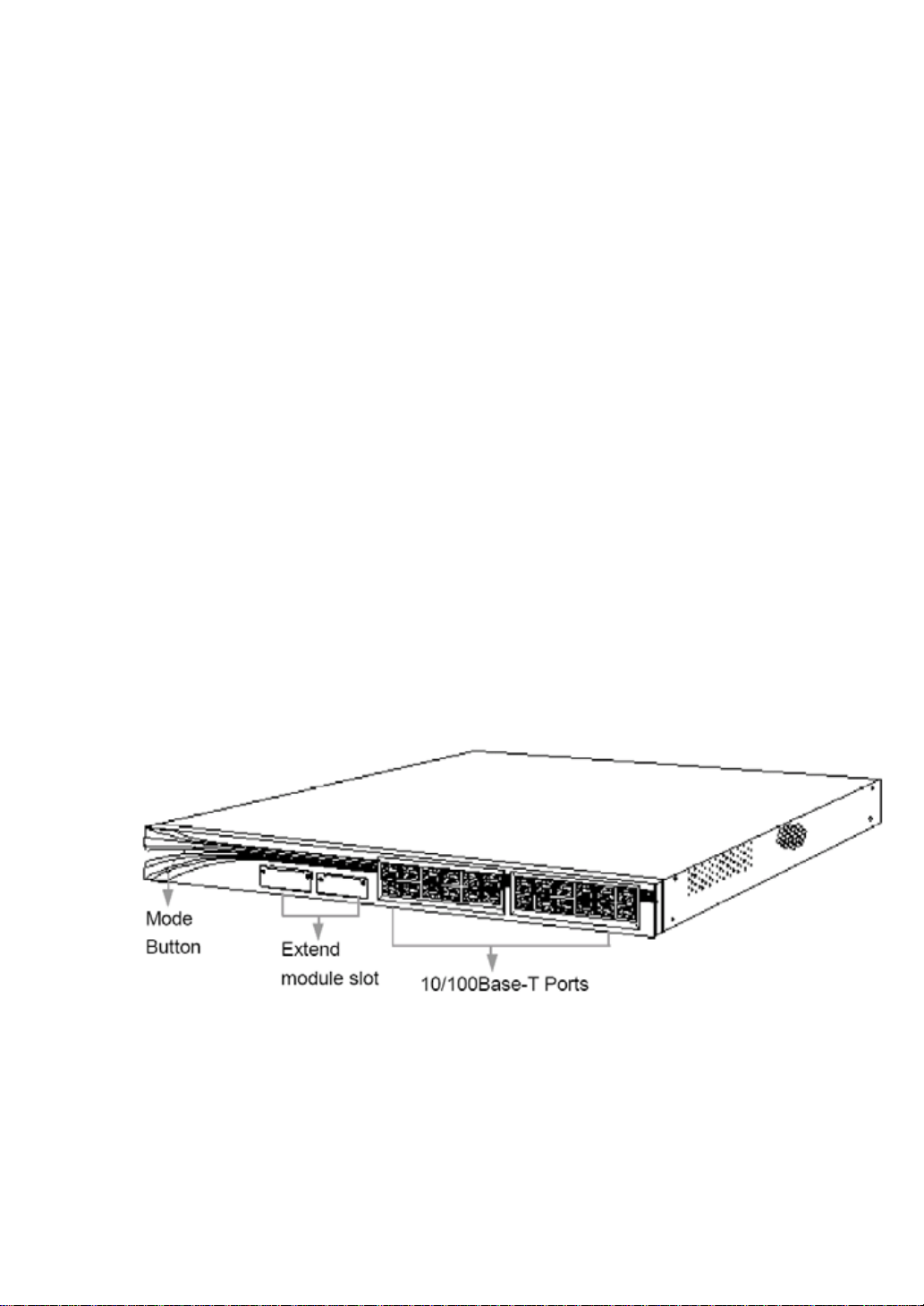
The outer look of the iSpirit 3026 switch is shown in Figure1-1.
Figure1-1.iSpirit 3026 switch model
Page 7

1.2 Product Characteristics
1.2.1 Technology Features
10/100Mbps ports which are self negotiable with either direct-connect cables or
cross-over cables;
10/100Mbps ports which are self negotiable and can be either in full-duplex mode or in
half-duplex mode;
Modules supported: 100M single-mode or multi-mode fiber modules , 1000M
single-mode or multi-mode fiber modules and 10/100/1000Base-T copper modules;
Supporting super-long cable, with a maximum CAT5 cable length of 140 meters;
Auto source address learning;
8K ARL table;
Providing flow control, and supporting IEEEE802.3X Head Of Line block and
backpressure;
Providing 4 priority queues and 802.1p priority match, thus providing flexible priority
control at port level for multimedia and other kinds of data transmission;
Supporting port binding with network adaptors, thus providing safe access;
Supporting port trunking, with a maximum of 6 groups, each of which supports a
maximum of 8 ports of same speed;
VLAN support: both port-based VLAN and 802.1Q tagged VLAN, with a maximum
configuration of 256 VLANs;
Supporting STP protocol;
Supporting MIB II and RMON, which has 4 different styles (Stastistics, History, Alarm
and Event);
LED status indicator lights with 4 modes
Static routing function
Supporting IGMP snooping
Supporting Xmodem software upgrading
Supporting 802.1x authentication protocol
1.2.2 Application Features
1. 100M and 1000M combination technology
The iSpirit 3026 switch supports fast Ethernet and 1000M Ethernet link aggregation, which
Page 8

allows network administrators to either aggregating 8 10/100 ports into one communication
tunnel, with a maximum of 6 trunk groups, or aggregating 2 Gigabit Ethernet ports into one
up-link communication tunnel.
2. Safety Feature
The iSpirit 3026 switch sup ports static configuration of ARL table and MAC address binding with
ports, thus provides MAC access filter; And the unique Hyper-safety technology can also
prevent forbidden or unallowed users to access network resources.
3. Powerful network management
The iSpirit 3026 switch uses Hype r-management tech nology and thus its ma nagement capa bility
is very powerful:
(1) can use Console and Telnet to configure with menu or CLI commands;
(2) can use a network management software based on SNMP;
(3) can configure through web with a graphics interface, which is convenient, powerful and
easy;
(4) it has been embedded with multiple network management agents, including Bridge
MIB, MIB II, Entity MIN version 2, RMON MIN and Proprietary MIB;
(5) support 4 groups of RMON network management protocols(1,2,3,9), providing various
information including statistics, history, warning and events information;
(6) easy to upgrade software: can use the in-band TFTP protocol for upgrading.
4. VLAN
The iSpirit 3026 switch supports port-based VLAN which conforms to 802.1Q standard.
1.3 Standard Protocols supported
Standard protocols supported by the iSpirit 3026 switch are shown in Table1-1.
Table1-1:
Protocols References
Bridge(tree protocol) IEEEE802.1d
Ethernet IEEE802.3
Fast-Ethernet IEEE802.3u
Complete full-duplex flow control IEEEE802.3x
Page 9

1000M Ethernet IEEEE802.3z
Link Aggregation IEEE802.3ad
VLAN IEEE802.1Q
UDP RFC 768,950,1071
TCP RFC 793
TFTP RFC 783
IP RFC 791
ICMP RFC 792
ARP RFC 826
Telnet RFC 854~ RFC 859
SMI RFC 1155
SNMP RFC 1157
MIBII RFC 1213 & RFC 1573
Ether-like MIB RFC 1398
Bridge MIB RFC 1493
Ether-like MIB RFC 1643
RMON RFC 1757
IBMPv2 RFC 1112
1.4 Description of Functionality
1.4.1 Port Trunking
Port Trunking is a technology which agg regates a network flow to a group of po rt s, thus provides
a communication channel of high bandwidth with error-free between switches. Network flows
can be distributed evenly between channels and thus provides load balance. Port trunking is
supported by the iSpirit 3026 switch.
Multiple physical ports can be combined to a logical port through port trunking. Features:
(1) If one port in the trunk group blocks or breaks down, data packets will be redistributed
evenly to other ports in the group;
(2) If the malfunction port goes back to normal, data packets will also be redistributed
among all ports in the group;
(3) Port trunking provided by the iSpirit 3026 switch is compatible with that provided by
Intel and Cisco.
Page 10

1.4.2 VLAN
1.VLAN introduction
VLAN is used for collecting all kinds of transmission devices in one physical local network. Any
combination of ports on a switch(including all ports) can be viewed as one VLAN. VLAN
assignment is not limited by physical connection between hardware devices, users can
configure VLAN flexibly by assigning different ports to different VLANs.
VLAN can relieve you from the restriction of physical connection when creating a broadcast
domain. A VLAN is just a set of local network devices which are independent from the physical
network topology. When they communicate with each other, all devices belong to one VLAN
seem to be in the same physical local network no matter how to connect them.
The main functionality of VLAN is as follows:
(1) can be used to constrain broadcast, flow-controlling its broadcast range. Here is an
example: suppose a device in the “Research Department” VLAN broadcast a data packet,
then only devices in the “Research Department” VLAN can receive this packet, other
devices in other departments won’t receive it;
(2) Provides additional safety. Communication between different VLANs can only be
achieved through layer 3 transmission, instead of direct communication;
(3) Make it easy to move and manage devices in the network.
In a word, VLAN is for the creation of layer 3 logical broadcast domains, it can be allocated
either on one switch, or through multiple switches. VLAN can be used for logical VLAN
separation of devices in one network with the same subnet address, i.e., separating them into
multiple broadcast domains, thus avoiding broadcast storm.
2.VLAN categorization
The iSpirit 3026 switch supports port-based VLAN. It allocates a set of ports on one or more
switches into one logical group, and this is the easiest and most efficient way. Network
administrators only need to assign a specific VLAN for a port, without considering the device it
connects. IEEE802.1Q is an international standard for port-based VLAN of Ethernet switches, it
allows the co-use of devices from different factories, with VLAN configurations to be understood
by each other, thus they can communica te with each other. According to IEEE802.1Q, a port can
be assigned as Tagged or Untagged, which determines whether the device that the port
connects can support frames with 802.1Q Tag header or not. The ports on the iSpirit 3026 switch
Page 11

can belong to multiple Tagged VLAN(identified by VLAN IDs) and one Untagged VLAN. The
range for VLAN Ids is from 1 from 4094. The iSpirit 3026 switch can have as many as 256
VLANs.
3.The application of tagged VLAN
Tagging is mostly used for VLAN configuration across multiple switches, where the connection
between switches is usually called “relay”. After tagging, a VLAN can be created among multiple
switches through one or more relays.
Another advantage for using tagging is that a port can belong to multiple VLANs, which is very
useful when you have a device(such as a server) that needs to belong to multiple VLANs, but
the device should have a network interface card which supports 802.1Q.
4.VLAN tag assignment
Every VLAN can be assigned a 802.1Q VLAN Tag. When a port is added to a VLAN with a
802.1Q Tag, it’s up to your choice whether it uses the VLAN tag. By default all ports on a switch
belong to a default VLAN, but they don’t use the VLAN ID of this default VLAN, it’s not necessary
for all ports to use a VLAN tag. When data packets are transmitted out of a port, the switch will
determine whether adding or removing the VLAN tag to/from the data packets based on the
VLAN configuration on the port.
5.Co-usage of tagged VLAN and port-based VLAN
You can co-use Tagged VLAN and Port-based VLAN. A port can belong to multiple VLAN, if it
only belongs to one untagged VLAN. In another word, a port can belong to one Port-based
VLAN and multiple Tagged VLAN.
1.4.3 STP(Spanning Tree Protocol)
The iSpirit 3026 switch support STP protocol with IEEE802.1d standard. STP runs on bridges
and switches, it’s a layer 2 protocol and is compatible with 802.1d standard. STP provides the
dynamic switching between redundant devices in the network, thus you can setup backup
communication channels in the network using STP, which guarantees that:
(1) The backup channel is close when the main channel is working normally;
(2) When the main channel breaks down, the backup channel is activated automatically,
Page 12
which let the data flow to be transmitted to the backup channel to make sure the device still
works normally. So STP can also avoid a loop when redundancy exists in the network topology.
On one hand, the existence of a loop will bring critical damage to the network; On the other hand,
it is very important to have a backup channel.
1.4.4 ARL table
ARL means Address Resolution Login, it’s the kernel part for transmitting packets in a Layer 2
switch. The iSpirit 3026 switch stores separately for unicast and multicast, named arl and marl
respectively. The hardware searches the arl table and the marl table for the related entry using
the destination MAC address in a data packet, and then outputs the packet to the port identified
by the entry. Table entries can be learned by the switch automatically through data transmission
through input ports, or can be added by network administrators to the arl and marl tables.
1.5 Front Panel
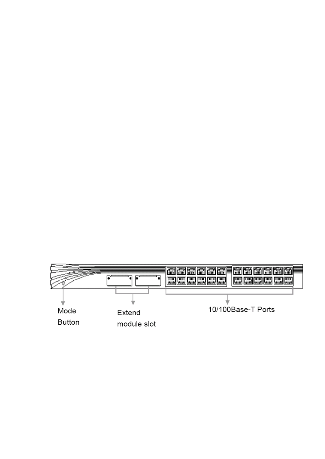
The front panel of the iSpirit 3026 switch have 24 10/100Base-T RJ-45 ports, 2 extendible slots,
ports LED status indicator lights, mode LED indicator lights and mode switches, etc… It’s shown
in Figure1-2.
Figure1-2.The front panel of the iSpirt 3026 switch
1.5.1 10/100Base-T ports
The longest cord length for 10/100Base-T ports is 140 meters. Network devices it can connect
include:
10Base-T compatible devices, such as work stations and concentrators connected
through RJ-45 interfaces using CAT3, CAT4, CAT5 or CAT5E cord;
100Base-TX compatible devices, such as those connected through RJ-45 interfaces
Page 13

using CAT5 or CAT5E cord, including high-speed work stations, servers, routers,
concentrators or other switches;
Notes:
(1) CAT3 and CAT4 cord can only allow 10Mbps data flow, while CAT5 and CAT5E can
have 100Mbps;
(2) 10/100Base-T ports can auto-negotiate using either direct-connect cable or crossover
cable.
Furthermore you can set the 10/100Base-T ports to half-duplex mode or full-duplex mode, 10M
or 100M and compose the two configurations at your intention. You can also set the ports to be
speed and duplex auto-negotiable according to IEEE802.3u standard. When a port is set to be
auto-negotiable, it will learn the speed and duplex info of the connected device and inform it its
own info. If the connected device is also auto-negotiable, the port will tune to the best
connection, i.e., set the speed to be the maximum both devices can support; and if the
connected device supports full-duplex, it will also use full-duplex.
More Info:
According to IEEE802.3u standard, the auto-negotiation process needs to create connections
for both devices to communicate and negotiate with each other, we recommend users to set
both connecting ports to be auto-negotiable, thus to make sure the auto-negotiation function is
able to tune the connection to the best status.
1.5.2 Extendible slots
The iSpirit 3026 switch have two extendible slots, which can use 100M single mode or multiple
mode fiber module, 1000M single mode or multiple mode fiber module or 10/100/1000Base-T
copper ports (shown in a previous chapter). The fiber configuration is shown in Table1-2.
Table1-2:
Fiber Module Medium Wavelength
single mode
multiple mode
single mode
62.5um multiple mode 100M
50um multiple mode
62.5um multiple mode 100M
50um multiple mode
62.5um multiple mode 550m 1000M
50um multiple mode
1300nm 20000m
1300nm 2000m
1300nm
Support
Max length
550m
Page 14
10um single mode 10000m
62.5um multiple mode 220m 1000M
multiple mode
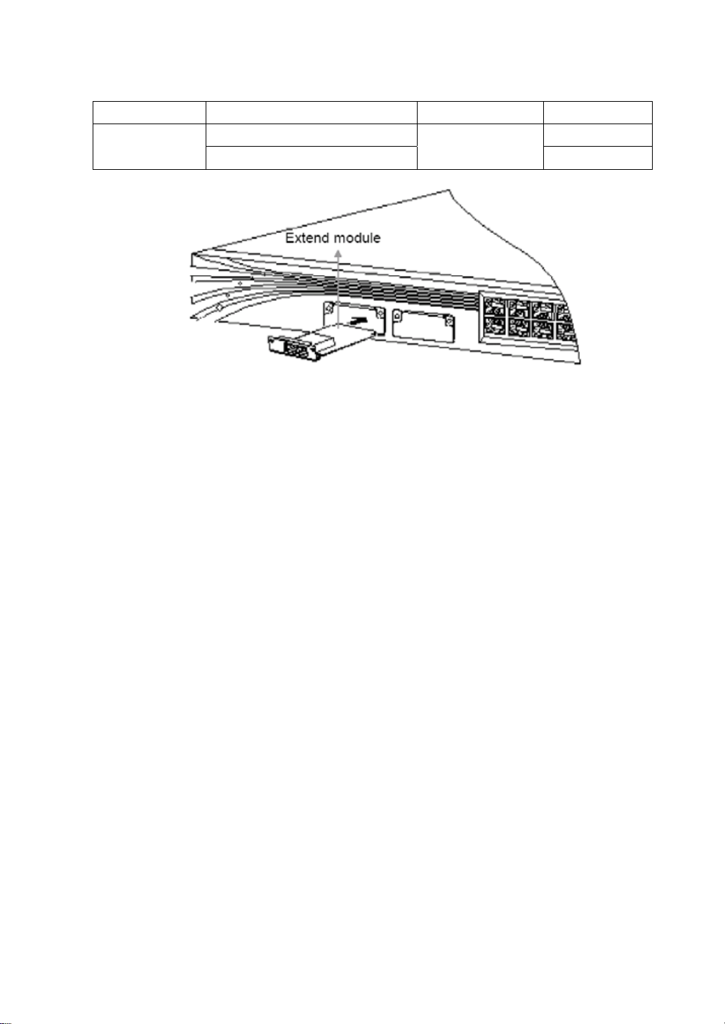
It’s shown in Figure1-3 how to insert a module to the extendible slot. Steps:
(1) insert the module into the slot along the track;
(2) make sure that the module fully inosculates with the slot;
(3) screw tightly;
Steps for removing a module is as follows:
(1) unscrew, both for the left side and the right side, to let the module deviate from the
panel;
(2) grasp tightly the screws on the left and the right, pull the module out in equilibrium and
make it separate from the box.
Notes:
Extendible modules don’t support hot-plug, so you must turn the power off before plugging or
unplugging, otherwise the switch may be damaged.
50um multiple mode
Figure1-3.how to insert a module to the extendible slot
850nm
500m
1.5.3 10/100/1000Base-T ports
10/100/1000Base-T ports can connect as long as 140 meters. Devices it can connect include:
10Base-T compatible devices, such as work stations and concentrators connected
through RJ-45 interfaces using CAT3, CAT4, CAT5 or CAT5E cord;
100Base-TX compatible devices, such as those connected through RJ-45 interfaces
using CAT5 or CAT5E cord, including high-speed work stations, servers, routers,
Page 15
concentrators or other switches;
1000Base-TX compatible devices, such as those connected through RJ-45 interfaces
using CAT5 or CAT5E cord, including 1000M work stations, servers, routers or other
switches.
Notes:
CAT3 and CAT4 cord can only allow 10Mbps data flow, while CAT5 and CAT5E can have
100Mbps and 1000Mbps.
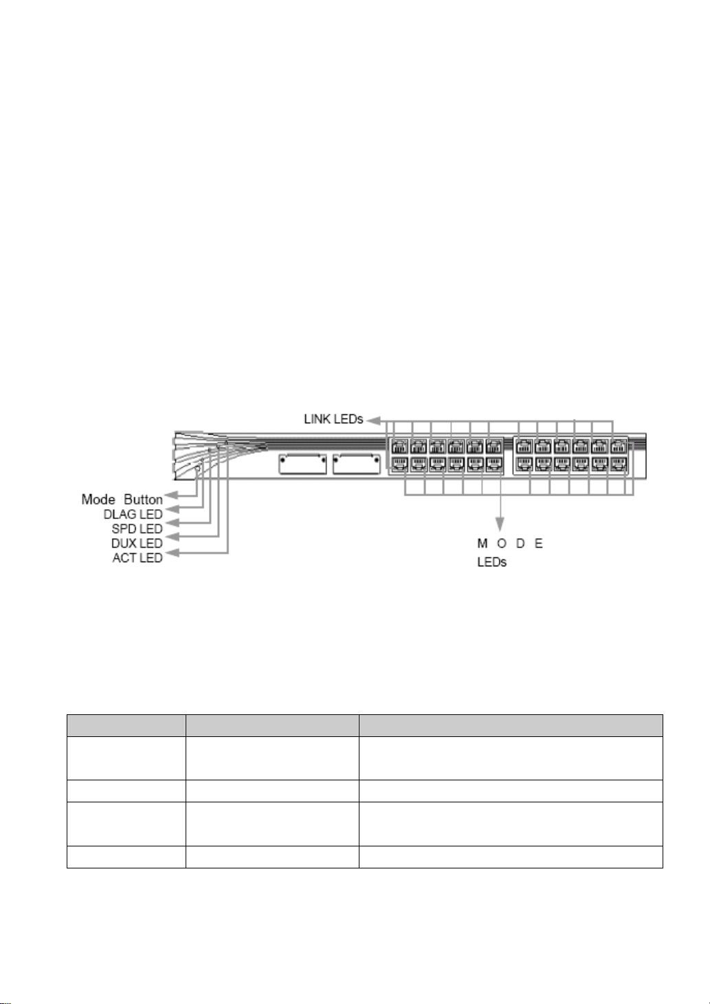
1.5.4 LED status indicator lights
Users can monitor the activity and performance of a switch through LED lights. Each port has a
pair of lights for its link status and one mode light. Link-LED, mode-LED and mode switches are
shown in Figure1-4.
Figure1-4.LED status indicator lights
1.Mode LED and mode switching
User can use the mode button to let mode LED showing related mode info. Users can choose
among modes including ACT, SPD, DUPX and DIAG. They are explained in Table1-3.
Table1-3:
Mode LED port mode description
ACT data receiving/sending
status
SPD speed speed:10M,100M or 1000Mbps
DUPX duplex mode duplex mode: half or full
DIAG diagnose to diagnose whether there is a problem
to show data receiving/sending status. It’s the
default mode.
diagnosis
2.Port status LED
Page 16

Table1-4 describes the color and related info of the port link status LEDs; Table1-6 explains the
same info in different mode.
Table1-4: color info of port link status LED
Port color link status
Connecting port
Table1-5: color info of port status LED under different modes
Mode color status
SPD
DUPX
none connectionless
green connected
none no data ACT
blinking green in transmission
10/100Base-T ports
None 10Mbps
green 100Mbps
1000Base-X GBIC module
green 1000Mbps
10/100/1000Base-T ports
none 10M or 100Mpbs
green 1000Mbps
10/100Base-T ports
None half-duplex
Green full-duplex
1000Base-X GBIC module
green full-duplex
10/100/1000Base-T ports
none half-duplex
green full-duplex
none normal DIAG
blinking green abnormal
1.6 Back Panel
There is an DC power plug and an UART console port, as shown in Figure1-5.
Page 17
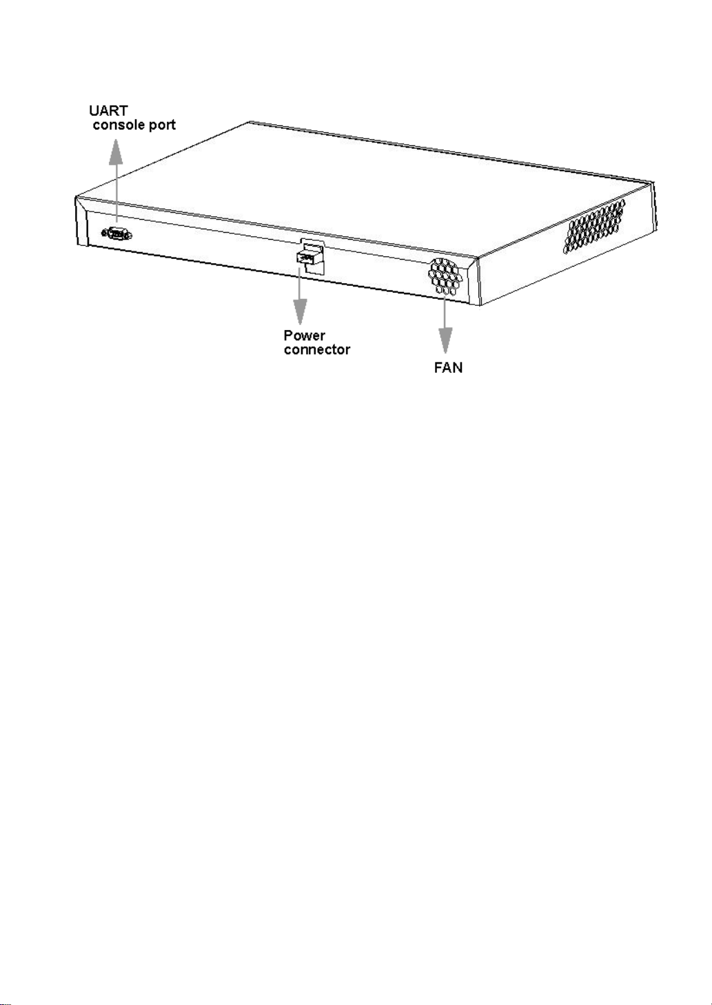
Figure1-5.iSpirit 3026 Back Panel
1.6.1 Power connection
The iSpirit 3026 switch supports 36V~72V DC power. An alternating current cable is needed to
connect with the power outlet.
1.6.2 COM
Users can use the UART port and the supplied console cord (specifically for this purpose) to
connect the switch with a PC in order to manage the switch. Pin description of the console cord
is shown in Appendix B
Page 18

Chapter 2.Installation and Startup
This chapter discusses how to install and start the iSpirit 3026 switch correctly and how to use
POST(Power On Self Test) to make sure the switch operates normally.
Chapter Index:
1. Help info before installation
2. Installation steps
3. Power on procedure
4. Explanation for bootrom startup options
5. Connecting steps
Page 19

2.1 Installation preparation
Before installing, users should read carefully the following warning information, we are not
responsible for any direct or indirect, intentional or un-intentional damage or hidden problem due
to incorrect installation.
Warning:
(1) Only trained and certified specialist can install or change the device;
(2) Users should read this manual carefully before power on the switch;
(3) Before operating on a turned-on device, users should remove any mental decoration
(such as rings, necklace and watches…), since the temperature of mental decorations
will go up quickly when contacting with the power and the ground, which may burn
yourself badly or melt the decorations down on the switch;
(4) Don’t put the box on the top of other devices. In case it falls down, it may hurt someone
or bring damages to devices;
(5) Users should make sure to be able to shut down the switch conveniently;
(6) To avoid the temperature of the switch to be too high, don’t let it run in an environment
with a temperature above the suggested 45 centigrade degree (113 degree for
Fahrenheit). To avoid limiting ventilation, don’t put anything else in the range of 7.6cm
(3 inches) at the ventilation intake;
(7) The iSpirit 3026 switch will work normal in TN power system;
(8) When installing the device, the ground cord should be connected first and unplugged
last;
(9) The device will use the existent short circuit protection means of the building, so make
sure fuses or turnoff switches are installed already;
(10) The device needs to be connected with the ground, so make sure that it connects the
ground during its usual operation;
(11) Be careful when turning on the switch to avoid overloading the power system;
(12) A mismatch ed volt age ca n either bring damag e to the device o r set of f file. In case the
voltage requirement on the device label doesn’t match with the power supply, don’t
connect them;
(13) If there is no power-on/off button on the device, you need to unplu g the power ca ble to
restarting the switch;
(14) Don’t touch the power supply in the switch before unplugging the power cord. For a
device with an on/off button, if the power cord is still connected but the device has
already been turned off, there is still voltage in the cord; The same thing for a device
Page 20

without an on/off button.
(15) Don’t operate on the device or connect /disconnect with it during flashing;\
(16) The handling of the device conforms to related national laws.?
2.1.1 Guideline for installation
The switch can be installed on a desk, in a rack, in a cabinet or on the wall. Before installation,
you need to turn on the switch and run POST to make sure it works fine. Please see “Power on
procedure” for more details.
Warning:
there is no back up accessories. You may make the repairing service guarantee statement
invalid by unscrewing, opening the box or decomposing the switch without formal permission.
Guideline for installation location
Please refer to the following information when you choose a location for the switch:
(1) The longest cable length is 140 meters for connecting from a 10/100Base-T port or a
10/100/1000Base-T port;
(2) The longest cable length is 10,000 meters for connecting from a 1000Base-X port;
(3) The cable should be far from any electromagnetic disturbance, such as a radio, power
supply cord or a fluorescent light;
(4) The space requirement for the front and back packet is as follows:
Users can see clearly LEDs on the front panel;
Users can use the ports conveniently so that the cord can be plugged/unplugged
easily;
The power outlet can be connected with power supply using the power cord;
There is no block in the range of 3 inches of the ventilation intake at the back panel;
(5) The required environment condition is explained in Appendix A;
(6) There should no block around the switch and the ventilation intake;
(7) The temperature around the switch should be lower than 40 centigrade degree.
Notes:
The switch will have a higher temperature than normal if it’s installed in a closed multi-layer
cabinet.
Page 21
2.2 Installation steps
2.2.1 Install on a desk and in a rack
When you install the switch on a desk or in a rack, please refer to the following steps:
(1) Four rubber underlays with adhesive tapes are provided with the switch. Pear off the
adhesive tape and adhere them to the lacunose positions at the bottom of the switch;
(2) Put the switch on the desk or in the rack near an DC power supply;
(3) Plug the power cord. After turned on, the system will run POST, please refer to “Power
on procedure” for more information.
2.2.2 Install in a cabinet
Warning:
To avoid hurt themselves during installation or operation, users should use effective method to
stabilize the switch. Please refer the following guidelines for safety:
(1) If there is only one device in the cabinet, install it at the bottom of cabinet;
(2) If more, install them down-to-up in the order of decreasing weight;
(3) If there are fixing equipments in the cabinet, please install them first before i nstalli ng the
switch;
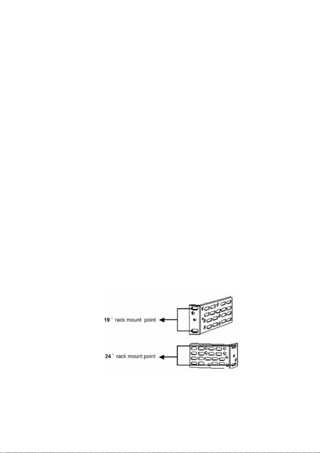
The supplied accessories for installation in a cabinet can be used for cabi net s of 19 inches o r 24
inches, the installation position is shown in Fighre2-1.
Fighre2-1. the installation position
Please refer to the following steps for installing in a 19 inches or 24 inches standard cabinet:
(1) Unscrew the switch;
Page 22
(2) Put the flanges on the cabinet;
(3) Install the switch into the cabinet
Fighre2-2. the installation position
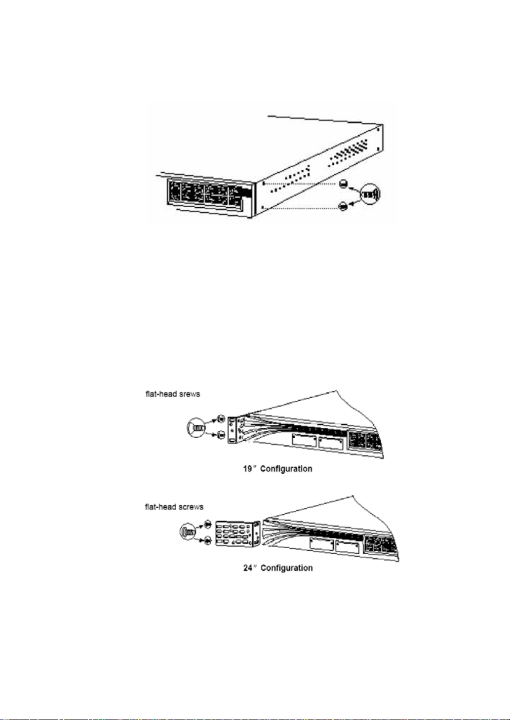
1.Put the flanges on the cabinet
The direction of the flanges and choice of the screws depend on the chosen 19 inches or 24
inches cabinet. Please refer to the following guideline to install two screws on each flange:
(1) e 19 inches cabinet, put the longer edge of the flange on the switch using supplied screws;
(2) 4 inches cabinet, put the shorter edge of the flange on the switch using supplied screws.
Figure2-3 and Figure2-4 show how to install the flang es at the front and back pa nel of the switch ,
respectively. You need to install simultaneously in reverse direction.
Figure2-3. how to install the flanges at the front panel of the switch
Page 23
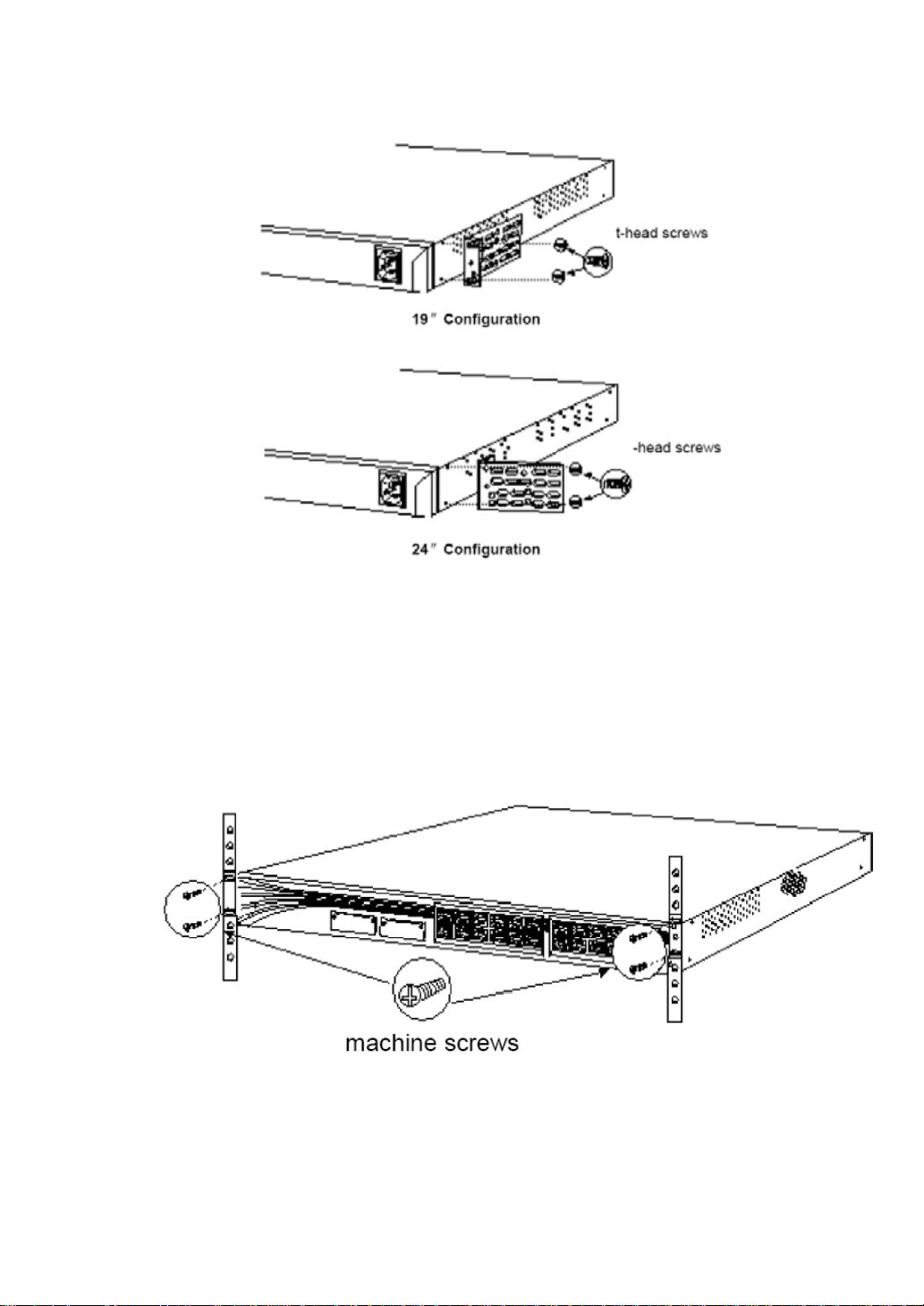
Figure2-4. how to install the flanges at the back panel of the switch
2.Install the switch into the cabinet
After installing the flanges on the switch, fix the flanges into the cabinet using supplied 4 screws
(as shown in Figure2-5), then plug the power cord into the switch. After turned on, the system
will first run POST, please refer to “Power on procedure” for more information.
Figure2-5.Install the switch into the cabinet
Page 24
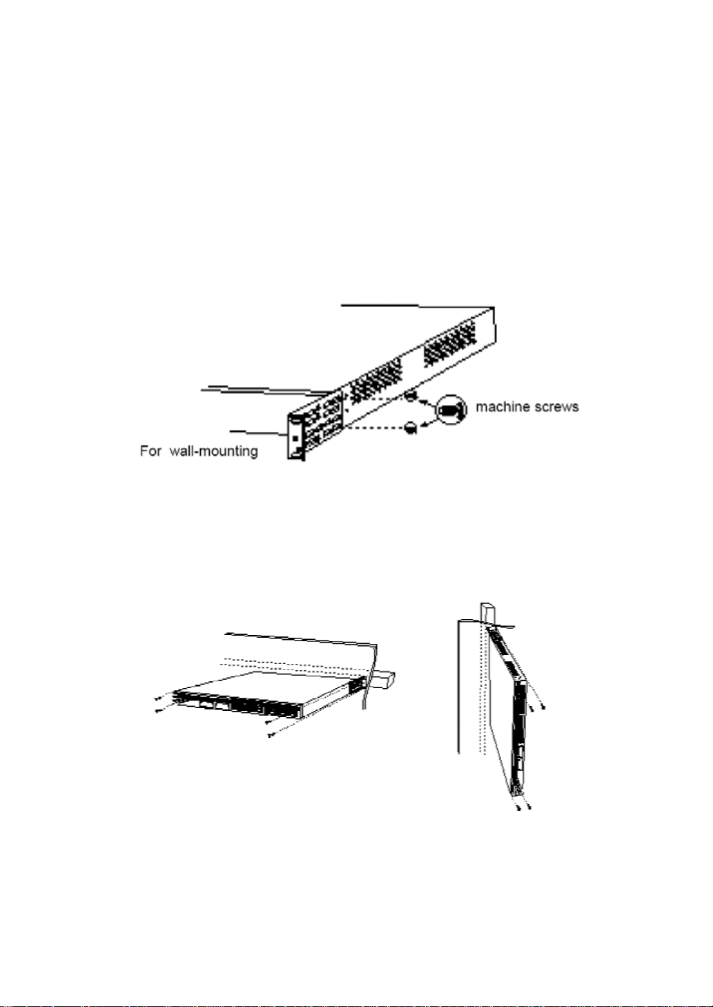
2.2.3 Install the switch on a wall
Two steps are necessary to install the switch on a wall:
(1) Install the flanges onto the switch;
(2) Install the switch onto the wall;
1.Install the flanges onto the switch
Users can install the switch on the wall either horizont ally or vertically based on th eir own choice.
Horizontal/vertical installation: install the longer edge of the flanges onto the switch using
supplied screws, and install the shorter on to the wall, as shown in Figure2-6.
Figure2-6.Install the flanges onto the switch
2.Install the switch onto the wall
To best support the switch and the network cable, users need to determine whether installing on
a pilaster or on a board (shown in Figure2-7), and then plug the power cord.
Figure2-7.Install the switch onto the wall
Page 25

2.3 Power on procedure
2.3.1 POST
After installation, power supply is necessary to turn on the switch:
(1) Plug one end of the power cord into the power jacket on the switch;
(2) Plug another end of the power cord into a power supply jacket.
After power on, all port status LEDs will turn on and then go out in a second, then the system will
go through the procedure of POST (Power On Self Test), during which the port status LEDs will
light one by one; After all LEDs are lighted, it means that the system has already passed POST,
and port LEDs are going to work in normal status; In ACT mode if LEDs are in good status, it
shows that the switch is working normally.
Please inform an authorized agent if your switch can’t pass POST.
2.4 Connecting steps
We’ll explain next how to connect a switch using the iSpirit 3026 switch as an example.
2.4.1 Connecting using the 10/100Mbps ports
10/100Mbps ports can be configured to use the same speed of the connected device. If the
connected device doesn’t support auto-negotiation, users can set the speed or duplex mode by
hand. Please refer to the following steps to connect a switch with a 10Base-T device or a
100Base-T device:
(1) For a 10Base-T device, connect it with a RJ-45 port on the front panel of the switch
using CAT3, CAT4, CAT5 or CAT5E direct-connected or crossover cable (as shown in
Figure2-8). Pin setting are shown in Appendix B;
(2) Connect the other end of the cable also with a RJ-45 port of the connected device. The
corresponding port LEDs should turn on after the connection, otherwise it may be due
to that the connected device is power off, there is a problem with the cable, or the
interface card has a problem.
(3) If necessary you may need to reconfigure the switch and restart;
(4) Repeat step1-3 to connect other needed devices to 10/100Mbps ports.
Page 26
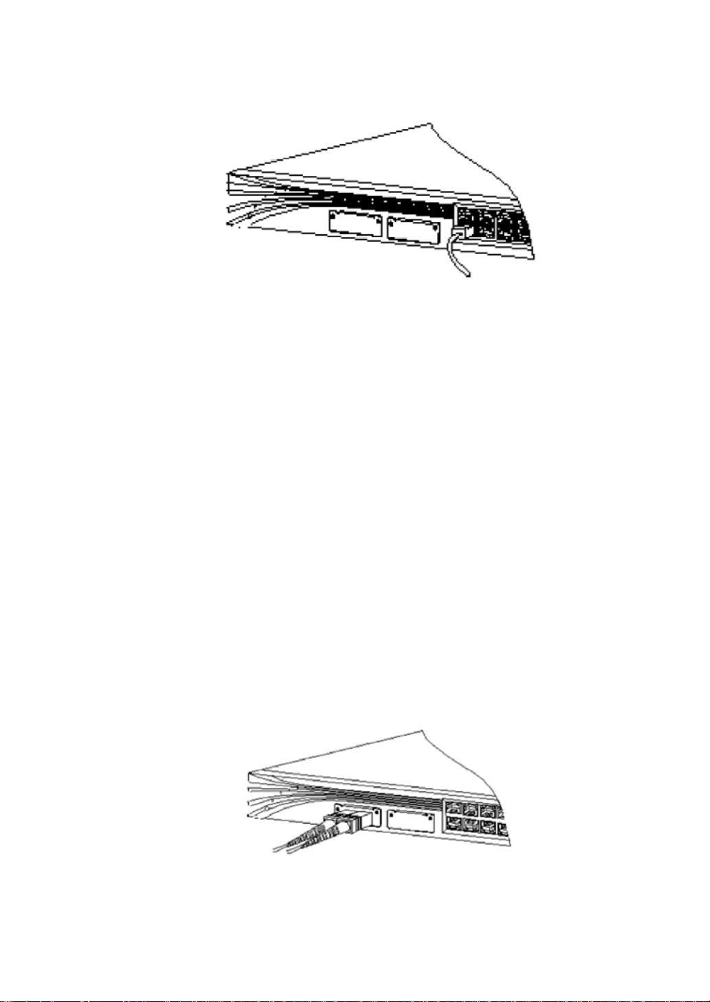
Figure2-8.Connecting using the 10/100Mbps ports
2.4.2 Connecting module ports
As explained in Chapter 1, install a 100Base-X fiber module and a 1000Base-X fiber module
using the extendible slots (can’t be hot-plugged).
Notes:
Please don’t remove the rubber stopple (at the ends of a fiber cable) and the rubber lid (on the
cable) before connecting, to avoid any stain or damage.
(1) Use direct-connected CAT5 or CAT5E cable to connect work stations, servers or
routers with RJ-45 ports at the front panel (as shown in Figure2-9), and use crossover
cable to connect with switches or concentrators. ? Pin description is shown in the
appendixes.
(2) Connect the other end of the cable with the RF-45 port of the connected device. The
corresponding port LEDs should turn on after the connection, otherwise it may be due
to that the connected device is power off, there is a problem with the cable, or the
interface card has a problem.
(3) If necessary you may need to reconfigure the switch and restart;
(4) Repeat step1-3 for other devices to 10/100/1000Base-T ports.
Figure2-9.servers or routers with RJ-45 ports at the front panel
Page 27

2.4.3 Connecting using the console port
Connect a PC or terminal with the console port using the supplied console cord (specifically for
this purpose). More information for the console port and cord can be found in Appendix B.
The PC or terminal should support VT100 mode. The terminal software (such as Hyperterminal,
an application software for PC) will create a communication channel between PC or terminal
with the switch when starting up.
Please refer to the following steps to connect a PC or terminal with the switch:
(1) Plug the supplied console cord into the UART console port on the switch as shown in
Figure2-10. Pin description is in Appendix B;
(2) Plug the other end of the cord to an UART COM port on the PC;
(3) Start the terminal program (such as Hyperterminal) if you are using a PC or terminal;
(4) Configure the text mode of the PC or terminal, such that it is the same as the
configuration of the console port of the switch:
Baud rate: 38400
Data bits: 8
Stop bit: 1
Checksum: none
2.5 Introduction to bootrom startup options
After power on, the system will go through the Bootrom startup procedure. Bootrom startup has
two ways: either automatic or by users.
2.5.1 Automatic startup
By default, after power on, the switch will enter automatic startup mode in 3 seconds without
Page 28
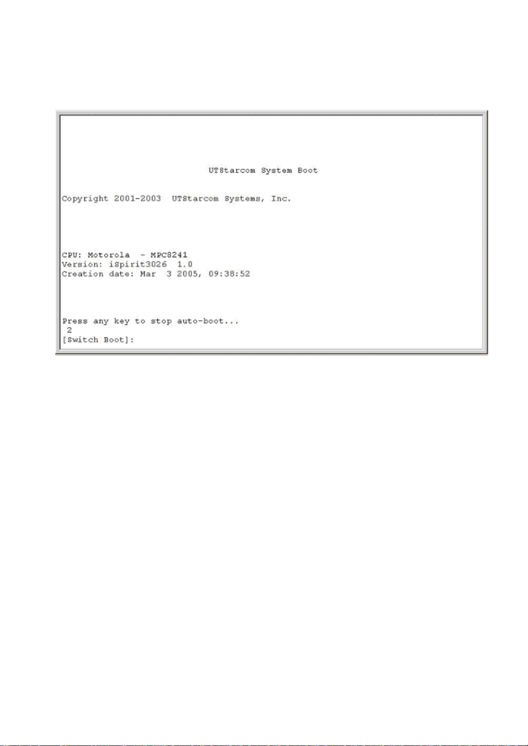
users’ intervention, then it will start the image program. The interface of waiting to enter startup
mode is shown in Figure2-11.
Figure2-1 1. Automatic startup
2.5.2 Startup by users
At the interface of waiting to enter startup mode, users can type any key except “@” to let the
system to step into Bootrom menu, which has a prompt of “[Switch Boot]”. At this prompt several
commands are available, and you can type “?” to get help. Help information is shown in
Figure2-12.
Page 29
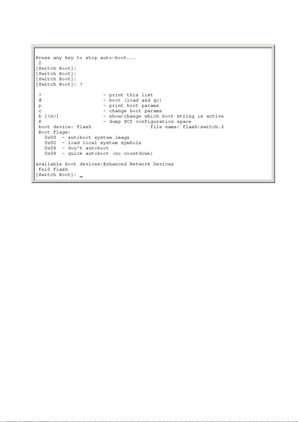
Figure2-12.Setup by users
Commands explanation:
?: to get help information
@: to start the image program
b<n>: to display or change the activated mode
p: to show startup parameters
c: to set startup parameters
P: to show all PCI devices
2.5.3 Upgrading Hyper OS using console port
At the prompt “[Switch Boot]:”, type a capital “§”, after a series of “§” signs ? are shown, choose
the “transfer” option from the terminal menu. set the protocol parameter to 1K Xmodem, then
click on the “transfer” button, which will start the downloading.
2.6 Next Step
Users can refer to the following chapters for more information on configuration and
management.
Page 30

Part 2 Software configuration
manual
Page 31

Chapter 1.Configure functionalities of common usage
In the iSpirit 3026 switch, some functionalities are simpler than others, but they are used often.
They are going to be introduced in this chapter.
Chapter Index:
1. Basic configuration of the system
2. File management configuration
3. Software upgrading
Page 32

1.1 Basic configuration of the system
Users can use CLI commands in the overall configuration mode (Switch#), these commands are
used for usual management of the switch, such as changing the password, showing the
configuration information, etc….
The system is in the EXEC mode first, type the command “enable” at this time and then type the
password, the switch will enter the overall configuration mode, shown as follows:
Switch>enable
Password:
Switch#
Commands lists:
to set the IP address and netmask of VLAN1 on the switch
ip address <ip-address><subnet-mask>
Example: Switch# ip address 192.168.2.3 255.255.255.0
to set the default gateway
ip gateway <gateway-address>
Example:
Switch# ip gateway 192.168.2.1
to restart the switch
Switch# reset
to restart the switch back to factory settings
Switch# reset factory
to change the password, which needs to be typed twice. This is an interactive command
Switch# password
to save configuration to flash
Switch# save
to go back to the upper level. If the system is currently in overall configuration mode, it will go
back to EXEC mode; if in EXEC mode, the command is just like a logout.
Switch# exit
To exit from the TELNET terminal. It is applicable to any CLI mode, but not
useful in console terminal.
Switch# logout
To clear information on the screen
Switch# cls
Page 33

To test the network connectivity between the switch and the machine at the other end
Switch# ping <remote-host>
Example:
support the IP address of a switch is 198.168.80.1, which has a directly connected PC with IP
address 198.168.80.72. To test the connectivity between the switch and the PC:
Switch# ping 198.168.80.72
If connected, it will show the connectivity as follows:
PING 198.168.80.72: 56 data bytes
64 bytes from host (198.168.80.72): icmp_seq=0. time=0. ms
64 bytes from host (198.168.80.72): icmp_seq=1. time=0. ms
64 bytes from host (198.168.80.72): icmp_seq=2. time=0. ms
64 bytes from host (198.168.80.72): icmp_seq=3. time=0. ms
64 bytes from host (198.168.80.72): icmp_seq=4. time=0. ms
--198.168.80.72 PING statistics—
5 packets transmitted, 5 packets received, 0% packet loss
round-trip (ms) min/avg/max = 0/3/16
If not connected, it will show as follows:
PING 198.168.80.72: 56 data bytes
no answer from 198.168.80.72
To show the last 20 commands
Switch# show history
To show system information, including system description, product name, version, and startup
time, etc…
Switch# show system
To show some configuration information, including IP address, MAC,IP gateway and protocols
startup information, etc…
Switch# show system
To show console connection parameters
Switch# show console
To show the height and width of the current terminal connection, i.e., the maximum number of
characters can be shown
Switch# show terminal
To show IP information of VLAN1, including IP address, netmask and gateway
Switch# show ip
To show version
Switch# show version
Page 34

To show all TCP and UDP connections
Switch# show connection
To clear TELNET password
Switch# clear telnet password
To get system time
Switch# get time
To set idletime before automatic logout from CLI
Switch# idletime <timeout>
To show idletime
Switch# show idletime
To set system time
Switch# set time
To set system prompt
Switch# switchname <switch-name>
1.2 File management configuration
After changing the configuration, you had better save it to flash, thus after reset, the
configuration will still work. Users can also download or upload configuration file using TFTP.
1.Commands
Users can save configuration under any CLI mode by just type the command “save”.
Under the overall configuration mode, you can backup the configuration file by uploading it to a
host
upload configuration <ip-address><file-name>
ip-address: the IP address of the destination PC for uploading
name: configuration file name
Under the overall configuration mode, you can download a configuration file from a host
download configuration <ip-address><file-name>
ip-address: the IP address of the source PC for downloading
name: configuration file name
(You need to start the TFTP program on the PC before the downloading/uploading)
Notes:
to let the configuration file take effect, the switch has to be restarted;
Page 35

2.File uploading/downloading procedure
Steps:
(1) set up the network environment. The PC host should be reachable from the switch that
needs to back up configuration file, you can use ping to test;
(2) save the configuration file at the switch;
(3) upload the file to the PC. Up to now the backup procedure has been fini she d, go to the
next step if necessary;
(4) download the backup configuration file to the switch.
Example:
a switch has been configured with VLANs and interface addresses, and it needs to backup the
configuration file:
Step 1: set up a network environment as shown in Figure1-1.
Figure1-1.Set up a networks environment
Use a console cord to connect the console port of the switch with a COM port on the PC, and
also connect them with a network cable. Install the TFTP server program on the PC, and
configure an IP address of the PC. Here suppose the IP address of the PC is 192.168.0.2. Then
configure an IP address of the switch, supposing it’s 192.168.0.1.
Notes:
PC IP address and switch IP address should belong to the same IP subnet.
To run TFTP server, you need to set the path information for the configuration file:
First, start TFTP Server program. The interface is shown in Figure1-2;
Page 36

Figure1-2.TFTP Server program
Then, set the path: Just click on the [Settings] button, a TFTPD32 configuration form will be
shown as in Figure1-3.
Figure1-3.TFTP Server program configuration
In the “Base Directory” bar type the path, then click on [OK] button to confirm;
Step 2: save the configuration to file at the switch
Under any CLI mode, just type the “save” command to save the configuration file.
Step 3: backup the file to the PC
Switch# upload configuration 192.168.0.2 backup
Page 37

Uploading configuration……
Complete
Switch#
Step 4: Download the file to the switch if necessary
Switch# download configuration 192.168.0.2 backup
Do you wish to continue ?[Y/N]: y
Downloading configuration……
Complete.
Step 5: reset
Do you wish to continue?
Y: yes; N: no
1.3 Software upgrading
The iSpirit 3026 switch supports on line software upgrading. Upgrading is also done by TFTP.
1.Commands
Under overall configuration mode, you can upgrade the image file of the switch:
Switch# Download image <ip-address> <name>
ip-address: the IP address of the PC where the image file is stored;
name: the image file name.
During the downloading process, DO NOT turn off the power, otherwise you may damage the
image file, then the switch may not be able to be restarted. After downloading, you need to
restart the switch to make the new image file taking effect.
2.Software upgrading procedure
(Similar as that for configuration file downloading)
Steps:
(1) Set up the upgrading environment
Step 1: set up the network connection as shown in Figure1-4;
Page 38

Figure1-4.Set up the net work connection
Step 2: connect the console port of the switch with a PC or terminal;
Step 3: inst all TFTP server on the PC (where the image file is saved);
Step 4: Copy the new image file to a directory on the PC, here suppose it’s C:\t;
Step 5: Configure an IP address of the PC, suppose it’s 192.168.0.2;
Step 6: Configure an IP address of the switch, suppose it’s `92.`68.0;
Notes:
PC IP address and switch IP address should belong to the same IP subnet.
(2) Start TFTP server.
Step 1: st art TFTP Server program. The interface is shown in Figure1-5.
Figure1-5.TFTP Server program
Page 39

Step 2: set the path. After starting TFTP server program, set the path information and copy the
new image file to this path. How: Just click on the [Settings] button, a TFTPD32 configuration
form will be shown as in Figure1-6.
Figure1-6.TFTP Server program configuration
(3) Configure the switch
Step 1: connect the switch. Choose a vlan interface and connect it with the PC (on which TFTP
server program is running) using a network cable, and use the “ping” command to test the
connection;
Step 2: Type the following CLI command on the switch and wait until the downloading process
has finished.
Switch# download image 1902.168.0.2 switch.img
Do you wish to continue ?[Y/N]: y
downloading image ……
Complete.
Switch#
Notes:
DO NOT turn off power during the process of downloading.
Step 3: rest art the switch
Switch# reset
Page 40

Chapter 2.Port Configuration
This chapter introduce port configuration.
Chapter Index:
1. Common configuration for ports
2. MIRROR configuration
3. TRUCK configuration
4. STORM-CONTROL configuration
5. Configuration examples
Page 41

2.1 Common configuration for ports
Users can control connections through a port via port configuration, for example they can
disable the port such that no connection are allowed through it. This sectio n introduce s com mon
configurations for ports, including:
Disabling and enabling a port
Setting port speed
Showing port information
1.Disabling and enabling a port
Ports on the iSpirit 3026 switch are enabled by default. If users want to deny any connection
through a port, they can disable the port.
To enable one or multiple contiguous ports under PORT RANGE configuration mode:
enable
For example, to enable port 1 and port2:
Switch(port1-2)# enable
To disable one or multiple contiguous ports under PORT RANGE configuration mode:
disable
For example, to disable port 1 and port2:
Switch(port1-2)# disable
2.Setting port speed
By default the speed for all ports is auto-negotiable. For 1000M ports, they can be
forced to be 10M half-duplex, 10M full-duplex, 100M half- or full-duplex.
To set speed under PORT RANGE configuration mode:
Speed <autonegotiate|half-10|full-10|half-100|full-100>
For example to set port 1 and port 2 to be 100M half-duplex:
Switch(port1-2)# speed half-100
3.Showing port information
To show one or multiple contiguous ports information under the overall or PORT
RANGE configuration mode:
show port <port|port1-port2>
For example to show port 1 and port 2 information:
Page 42

Switch# show port 1-2
2.2 MIRROR configuration
Mirror is a very useful functionality which can be used to monitor data packet flow through a port,
both for receiving and sending. It can use the mirror port to monitor data packets of other
mirrored ports.
The iSpirit 3026 switch sup port s mirror functionality, and can mirror multiple ports simultaneously,
both for in-packets and out-packets.
This section describes mirror configuration:
Mirror Egress
Mirror Ingress
Mirror Port
1.Mirror Egress
Egress configuration sets egress ports, whose sending packets will be monitored.
2.Mirror Ingress
Ingress configuration sets ingress ports, whose receiving packets will be monitored.
3.Mirror Port
Mirror port configuration is to set the port that’s used to monitor packets. The CLI command is
interactive, users just need to type the port number.
Notes:
(1) Mirror egress and mirror ingress can’t include mirror port;
(2) can only set one mirror port.
2.3 TRUCK configuration
Trunk is to aggregate multiple ports into one logical port, it can used to increase port bandwidth,
providing redundancy and load balance.
Trunk is a simple method for aggregating multiple ports to one. As a logical destination port, the
switch will choose one physical port to send packets based on the aggregation policy of the
software. Trunk functionality and aggregation policy are accomplished by software, if trunk is
used for redundancy, the software should also check ports status and reorganize trunk
Page 43

dynamically.
All ports in a trunk group should have the same speed and be in full-duplex mode. Trunk is a
layer 2 functionality, it’s supported by the iSpirit 3026 switch.
The iSpirit 3026 switch can support 6 trunk groups, each of them can have a maximum number
of 8 ports. And each port can only belong to one trunk group.
To set load balance policy, we currently provide 6 options, which sets the Rtag to be 1-6:
1. load balance based on source MAC address for non-IP packets
2. load balance based on destination MAC address for non-IP packets
3. load balance based on the pair of source and destination MAC address for non-IP packet s
4. load balance based on source MAC and source IP address for IP packets
5. load balance based on destination MAC and destination IP address for IP packets
6. load balance based on both of source and destination MAC and IP address for IP packets
This section will introduce the following information:
Trunk configuration
Trunk mcast configuration
Trunk no ports configuration
Trunk ports configuration
Trunk Rtag configuration
To show trunk information
1.Trunk configuration
To configure a trunk group, firstly type the trunk ID, there can be 6 of them; Secondly enter trunk
Rtag, which has 6 load balance options; thirdly enter ports identification including module
numbers and port numbers, which can have a maximum of 8. The CLI command is:
trunk
It’s an interactive command, users just type the corresponding parameters acco rding the prompt
information, including Trunk ID, Rtag, and trunk port list.
2.Trunk mcast configuration
Trunk mcast configuration adds an existent trunk group to a multicast group. It requests that the
trunk ports should be a subset of the multicast ports group. Configure steps: firstly remove trunk
ports from the multicast group; then add one port in the trunk group to the multicast group ag ain,
by default the added port is the one with the minimum port number in the trunk group. The
command is:
trunk mcast
Page 44

It’s an interactive command.
3.Trunk no ports configuration
This configuration is to remove ports from a trunk group. Command:
trunk no ports <trunk_id> <port|port1-port2> [port|port1-port2]…
4.Trunk ports configuration
This configuration is to add ports to a trunk group. Command:
Trunk ports <trunk_id> <port|port1-port2> [port|port1-port2]…
5.Trunk Rtag configuration
It’s to set or change the load balance policy of a trunk group. The iSpirit 3026 switch allows
setting the policy separately for each trunk group. Command:
Trunk rtag <trunk_id> <rt ag>
6.To show trunk information
Under the overall configuration mode users can show trunk configuration information using
command “show trunk”:
Switch# show trunk
2.4 STORM-CONTROL configuration
In real networks, DLF (Destination Lookup Failure, when packets will be handled like broadcast
packets), multicast or broadcast transmission in high speed can block the network, thus it’s very
important to be able to control such kind of storm traffic, to avoid network blocking. All ports of
the iSpirit 3026 switch support storm cont rol for broadcast, multica st and DLF p acket s. They can
limit the transmission speed of broadcast packets, multicast packets and DLF packets.
This section introduces storm-control configuration:
Default configuration
Storm-control configuration
To show storm-control configuration
1.Default configuration
All ports of the iSpirit 3026 switch can set broadcast rate, multicast rate and dlf rate. By default
Page 45

broadcast rate (upper limit) is set to 1500 packets per second, to avoid broadcast storm. No
default configuration for multicast and dlf unicast.
2.Storm-control configuration
Storm-control configuration of the iSpirit 3026 switch is identical for all ports. The storm-control
command is interactive and users need to type corresponding parameters, and the setting is
valid for all ports after configuration.
Switch# storm-control
It’s an interactive command, users need to enter parameters including whether to control
broadcast, multicast and DLF, and the upperlimit rate, which is the same for all the 3 kinds of
transmission style.
3.To show storm-control configuration
Under the overall configuration mode or PORT RANGE mode, to show configuration
information:
show storm-control
2.5 Separated port configuration
In real network, users usually need network separation for data safety. The iSpirit 3026 switch
provides several methods for separation: VLAN, private VLAN, protected VLAN and separated
port. Separated port technology are to employed in one VLAN, users can set explicitly the
egress port for the separated port, such that the separated port can only communicate with the
specified egress port, and NOT with other ports in the vlan. Separated port is more flexible than
protected vlan.
Commands(used under PORT RANGE configuration mode):
1. To configure separation such that the separated port can only communicate with the
uplink port:
separated
2. To unset separation:
no separated
3. to show separation configuration, either for one port or for all ports(this command can
also be used under the overall configuration mode):
show separated [port]
Page 46

2.6 Jumbo frame port configuration
In real networks, it’s necessary to transmit jumbo frames (i.e. super-sized) for some special
applications such as server clusters. The iSpirit 3026 switch supports jumbo frames
transmission.
Commands(can be used either in PORT RANGE mode or overall mode):
1. to set jumbo frame for ports
jumbo size <frame-size> <port|port1-port2>
2. to show jumbo frame configuration for all ports
show jumbo
2.7 Configuration examples
1.Mirror
Figure2-1.Configuration examples
As shown in Figure2-1, user 1 and user2 are communicating through a switch, usually other
users won’t be able to know the exchanging information between them. To check whether there
is any problem with the communication, a monitoring user wants to capture the data packets
transmitted between them, which will need port mirror functionality. Suppose user 1 connects to
port 1, user 2 connects to port 2, the monitoring user connects to port 3. Commands list:
Page 47

To monitor data from/to user 1
Switch# mirror
Mirror port: 3
Egress ports_list: 1
Ingress ports_list: 1
To monitor data from/to user 2
Switch mirror
Mirror port: 3
Egress ports_list: 2
Ingress ports_list: 2
Notes:
Don’t mess up mirror port and mirrored ports. Mirror port is the port that’s used to monitor data
packets; Mirrored ports are the ports that are being monitored and whose packets are going to
be captured, they include egress ports and ingress ports.
To show mirror configuration
Switch# show mirror
Mirror mode: L2
Mirror port: 3
Egress ports_list: 2
Ingress ports_list: 2
2.Trunk (Figure 2-2)
Figure 2-2.Trunk configare
Page 48

To configure a trunk between switch 1 and switch 2, each with port 1-4 in the trunk
group.
Type the following commands on each switch:
Switch# trunk
Trunk_id: 1
Trunk_rtag: 1
Ports _list: 1-4
Notes:
When configuring a trunk, both switches should have the same num ber of port s in the trunk, wit h
the same speed and duplex configuration, but the port identification number can be different.
To delete a trunk group
Switch# no trunk A
A: trunk id, range: 0-5
To check any error
(1). If the trunk doesn’t work, check the status:
switch# show trunk
TGID RTAG status Ports
0 0 not ready 0x00000000(none)
1 1 Active 0x0000000f(fe1-fe4)
2 0 not ready 0x00000000(none)
3 0 not ready 0x00000000(none)
4 0 not ready 0x00000000(none)
5 0 not ready 0x00000000(none)
Thus you can check whether the configured trunk i s active, whether the included port s number is
correct and whether member ports are correct.
(2) Ports in the same trunk should belong to the same vlan, with the same speed and
duplex configuration.
Page 49

Chapter 3.VLAN Configuration
VLAN is a very important technology in a switch, it’s used often in real networks and is a critical
method to partition the whole network topology to multiple subnetworks. VLAN means Virtual
Local Area Network, it’s a logical network by organizing together multiple devices, no matter
where they are physically in the network. Though logically, each vlan has the same functionality
and characteristics of traditional physical networks. Each vlan represents a broadcast domain,
broadcast packets can only transmit inside the vlan, not allowed to span multiple vlans.
Communication spanning multiple vlans needs to accomplished by layer 3 transmission.
The iSpirit 3026 switch su pports VLAN and Private VLAN, so usually VLAN is also called normal
VLAN. This chapter introduces normal VLAN configuration, for private VLAN, please refer to the
corresponding chapter.
Chapter Index:
1. Introduction to VLAN
2. VLAN configuration
3. VLAN examples
Page 50

3.1 Introduction to VLAN
This section will give detail information for VLAN:
Benefit of VLAN
VLAN ID
Member ports types of VLAN
VLAN relay
Data transmission in a VLAN
VLAN vs. Private VLAN
Subnetworks of VLAN
1.Benefit of VLAN
VLAN can extend a physical network to a large degree. Traditional physical networks can be
very small, usually with up to 1000 devices, while physical networks with VLAN partitions can
have 10,000 or even 100,000 devices. VLAN has the same functionality and characteristics as
the traditional physical network.
Advantages:
VLAN can control data flow in the network
In traditional networks, all broadcast packets are transmitted to all devices, no matter whether
needed or not, thus increasing the load of the network and the devices; While VLAN can
organize devices into one logical network when needed. One VLAN represents one broadcast
domain, broadcast packets can only transmit inside a VLAN, not across multiple VLANs. So
VLAN partition can control effectively data flow in a network.
VLAN can improve network security
Devices in a VLAN can only set up Layer 2 communication among themselves, communication
with another VLAN must go through Layer 3 transmission. Without Layer 3 transmission, no
communication is allowed between VLANs at all, thus VLAN can provide isolatio n and keep d ata
safety in a VLAN. For example, the “research” department in a company doesn’t want to share
data with the “marketing” department, then two VLANs can be created for them, one for each of
them, without Layer 3 transmission.
VLAN makes it more convenient to move devices
When a device in a traditional network is moved from one position to another, usually the
network administrator has to modify its configuration, which is inconvenient for users. For VLA N,
since a VLAN is a logical network, it can allocate devices in different locations into the same
Page 51

logical network; when a device is moved, it still belongs to the same VLAN, so it’s not necessary
to modify its configuration.
2.VLAN ID
Each VLAN has an identification number called VLAN ID (VID), with a range of 0~4095, during
which 0 and 4095 are not used, so the VLAN ID only ranges from 1 to 4094. One VLAN has only
one VLAN ID.
The iSpirit 3026 switch can suppo rt a maximum of 255 VLANs. Users need to choose a VLAN ID
among 1-4094 when creating a VLAN.
There are three kinds of frames transmitted in a VLAN: non-tagged frame, frame with VID 0,
frame with VID nonzero. Data packets for these 3 frames are shown in Figure3-1.
Figure3-1.3 Data packets for these 3 frames
All frames are tagged inside a switch. If a non-tagged frame is transferred to the switch, it will t ag
the frame by choosing a VLAN ID and filling it into the frame VID; If a frame with VID 0 is
inputted, the switch will also choose a VLAN ID for it; For a frame with a nonzero VID, no change
by the switch.
3.Member ports types of VLAN
The iSpirit 3026 switch supports Port-based VLAN and 802.1Q VLAN. A VLAN has two kinds of
ports: untagged port and tagged port, and a VLAN can have them simultaneously.
There can be no port, one or more ports in a VLAN. When a port belongs to a VLAN, it can be
either untagged or tagged.
A port can be an untagged member port of only one VLAN. When a port is configured to be
Page 52

untagged of a VLAN, if it’s already an untagged member of another VLAN, it will be removed
from it, i.e., the last configuration takes effect.
A port can be an tagged member port of multiple VLANs. In this case, it’s also called VLAN
Relay Port. A port can belong to a VLAN as untagged and belong to other multiple VLANs as
tagged simultaneously.
4.VLAN relay
If a port is a tagged member port of two or more VLANs, it’s also called as a relay port of VLAN.
Two swit ches can conne ct through a relay port, thus they can have two or more common VLAN s
between them.
A relay example is shown in Figure3-2: Two switches connect through a replay port, which
belongs to VLAN 2 and VLAN 3. Each switch has two VLANs, VLAN 2 and VLAN 3, and each
VLAN has a user. Thus user 1 can communicate with user 3, user 2 with user 4, but user 1 can’t
with user 2, neither for user 3 with user 4.
Figure3-2. Relay Port Vlan
5.Data transmission in a VLAN
When a switch receives a data packet from a port, it will follow these steps for layer2
transmission:
Determine which VLAN this packet belongs to;
Check whether it’s broadcast, multicast or unicast;
Determines output ports based on its type, there can be 0 ports, one or more ports. If
0,discard the packet;
Tag or untag the packet based on the member port type;
Send the packet.
(1) To determine which VLAN this packet belongs to:
Page 53

If the received packet is tagged with a nonzero VID, the VLAN it belongs to is identified by the
VID; if the packet is non-tagged or with a VID of 0, if the input port is an untagged member port
of a VLAN, this VLAN is the one that the packet belongs to; otherwise, if the input port is not an
untagged member of any VLAN, the packet will be discarded.
(2) To check packet type:
If the received packet has a destination MAC address of FF:FF:FF:FF:FF:FF, it’s a broadcast
th
packet; If not broadcast while have a destination MAC address with the 40
bit being 1, it’s a
multicast packet; Otherwise, it’s a unicast packet.
(3) To determine output ports:
For a broadcast packet, the output ports include all member ports of the VLAN that the packet
belongs to.
For a multicast packet, firstly search the hardware Layer 2 multicast transmission t able based on
the multicast MAC address and the VLAN it belongs to. If matching multicast entries are found,
the intersection of output ports of the multicast entries and member ports of the VLAN are the
output ports for the packet; If no common port, the packet will be discarded; If no multicast entry
is found, the output ports will be determined based on the transmission mode of Layer2
hardware multicast transmission table: for unregistered multicast transmission mode, multicast
packets are handled the same as for broadcast p acket s, i.e., the output port s incl ude all member
ports of the VLAN the packet belongs to; for registered mode, there will no output port, and the
packet will be discarded.
For a unicast packet, firstly search the hardware Layer 2 transmission table based on the
destination MAC address and the VLAN it belongs to. If matching entries are found, the
intersection of output ports of the entries and member ports of the VLAN are the output ports for
the packet; If no common port, the packet is discarded; If no entry is found, the packet will be
handled the same as for broadcast packets, i.e., t he output ports include all member ports of the
VLAN the packet belongs to.
(4) To send a packet
The packet will be sent to all output ports determined in the previous step.
If a output port is an untagged member of the VLAN the packet belongs to, the packet will be
sent without a VID tag; Otherwise, if tagged member, the packet will be tagged with the VLAN
ID.
Page 54

6.VLAN with Private VLAN
Since the iSpirit 3026 switch supports private VLAN, the “VLAN” is also called as normal VLAN.
Normal VLAN and private VLAN are mutually exclusive in some degree.
A normal VLAN represents a broadcast domain, each VLAN can form a sub-network, and
communication across VLANs should go through Layer 3 transmission; while for private VLAN,
a broadcast domain needs a private VLAN group. Each private VLAN group can form a
sub-network, which is created in the main VLAN of the private VLAN group. Communication
across multiple private VLAN groups should go through Layer 3 transmission, while
communication inside a group just needs Layer 2 transmission.
When creating a normal VLAN, users should make sure that the normal VLAN doesn’t fall in the
range of any private VLAN of any private VLAN group. Otherwise, it won’t be created.
When adding a port to a private VLAN, it can be a promiscuous port, a shared port or a
separated port. No matter what kind of port it is, if it’s an untag ged member of a normal VLAN, it
should be removed from the normal VLAN first.
When adding a port to a normal VLAN, if the port already belongs to a private VLAN, it can’t be
set as an untagged member of the normal VLAN, but can be a tagged member.
The command “show vlan” will only show information for normal VLANs. To show private VLAN,
please use the command “show privatevlan”.
(Please refer to Chapter 4 for more information.)
7.Sub-networks of VLAN
A VLAN repre sents a broadcast domain in the iSpirit 3026 switch, and a subnet interface can be
created for each VLAN (actually all subnets are created based on VLAN.). The iSpirit 3026
switch can support a maximum number of 4094 VLANs, but can only have 26 subnets. After
creating subnets on 26 VLANs, other VLANs can’t have any more subnet.
3.2 VLAN configuration
For the convenience of users, the iSpirit 3026 switch provides various of commands for VLAN
Page 55

configuration. They are mostly used under the VLAN configuration mode and th e POR T RANGE
mode.
By default the iSpirit 3026 switch has VLAN 1, which has all of the ports as untagged members.
This section gives detail information for VLAN configuration:
To create and delete a VLAN;
To configure an untagged member of a VLAN;
To configure a tagged member of a VLAN;
To show VLAN information
1.To create and delete a VLAN
Users can create one or more contiguous VLANs using one command. The following command
creates VLANs under the overall configuration mode. If a vlanid is entered, it will create the
mentioned VLAN and go to the VLAN mode; if the mentioned VLAN has been created before, it
will just go to the VLAN mode without creating again; If a VLAN range like minvlanid-maxvlanid
is entered, multiple contiguous VLANs will be created, but it won’t go to the VLAN mode; in case
VLANs in the range are already existent, then no creation. The command:
vlan {<vlanid>|<minvlanid-maxvlanid>}
Users can delete one or more contiguous VLANs using one command. The following command
deletes VLANs under the overall configuration mode. If a vlanid is entered, it will only delete the
mentioned VLAN; If the mentioned VLAN doesn’t exist, no operation is done; If a VLAN range
like minvlanid-maxvlanid is entered, multiple contiguous VLANs will be deleted; in case VLANs
in the range don’t exist, then no operation is done. Once a VLAN is deleted, all port membership
of this VLAN will also be removed. The command:
no vlan {<vlanid>|<minvlanid-maxvlanid>}
Notes:
If a VLAN is owned by a private VLAN, it can’t be created or deleted.
2. To configure an untagged member of a VLAN
At the iSpirit 3026 switch, users can set untagged member ports either under the VLAN
configuration mode or under the PORT RANGE mode.
To add untagged ports under VLAN mode:
Page 56

untagged {<port>|<port1-port2>} [<port>|<port1-port2>] …
To delete untagged ports under VLAN mode:
no untagged {<port>|<port1-port2>} [<port>|<port1-port2>] …
To add untagged ports to one or multiple contiguous VLANs under PORT RANGE
mode:
untagged-vlan {<vlanid>|<minvlanid-maxvlanid>} [<vlanid>|<minvlanid-maxvlanid>]…
To delete ports from one or multiple contiguous VLANs under PORT RANGE mode:
nountagged-vlan{<vlanid>|<minvlanid-maxvlanid>}[<vlanid>|<minvlanid-maxvlanid>]
…
Notes:
If a port already belongs to a private VLAN, it can’t be an untagged member of a normal VLAN;
If a port already belongs to a normal VLAN as untagged, it should be deleted from the VLAN,
before adding it to a private VLAN.
3. To configure a tagged member of a VLAN
At the iSpirit 3026 switch, users can set tagged member ports for one or multiple contiguous
VLANs either under the VLAN configuration mode or under the PORT RANGE mode.
To add tagged ports under VLAN mode:
tagged {<port>|<port1-port2>} [<port>|<port1-port2>] …
To delete tagged ports under VLAN mode:
no tagged {<port>|<port1-port2>} [<port>|<port1-port2>] …
To add tagged ports to one or multiple contiguous VLANs under PORT RANGE mode:
tagged-vlan {<vlanid>|<minvlanid-maxvlanid>} [<vlanid>|<minvlanid-maxvlanid>] …
To delete ports from one or multiple contiguous VLANs under PORT RANGE mode:
notagged-vlan {<vlanid>|<minvlanid-maxvlanid>} [<vlanid>|<minvlanid-maxvlanid>] …
4. To show VLAN information
At the iSpirit 3026 swit ch, users can show VLAN i nformation under multiple configuratio n modes,
including VLAN overview and member ports information.
To show VLAN information: without any p arameter, it will show overview information for
all VLANs; with VLAN ID parameters, it will show member ports for one or multiple contiguous
VLANs.
Show vlan [<vlanid>|<minvlanid-maxvlanid>]
Page 57

3.3 VLAN examples
Figure3-3.Vlan example
As shown in Figure3-3, there are two users: user 1 and user 2. Since the networks they use
have different network functionality and different environment, it’s necessary for them to belong
to different VLANs. User1 is in VLAN 2, connecting port 2 of a iSpirit 3026 switch, while user 2 is
in VLAN 3 with port 3. Configuration:
Switch# vlan 2
Vlan 2 added
Switch(vlan-2) exit
Switch# vlan 3
Vlan 3 added
Switch(vlan-3) vlan 2
Switch(vlan-2) untag 2
Switch(vlan-2) vlan 3
Switch(vlan-3) untag 3
Switch(vlan-3) exit
To check errors:
After configuration, if you find that PCs can’t communicate with each other across different
VLANs, it’s ok, since communication across different VLANs should go through Layer 3
Page 58

transmission.
In case PCs in the same VLAN can’t communication with each other, you should check:
1、VLANs already existent:
Switch# show vlan
member port information for related VLANs
switch# show vlan 2
vlan 2 port map
(-=None,M=Tagged,U=Untagged)
switch# show vlan 3
vlan 2 port map
Page 59

Chapter 4.Private VLAN configuration
To share common data while ensuring safety of private data in real networks, there are many
Layer 2 isolation technologies. UTStarcom proposed a new idea of Private VLAN in the iSpirit
3026 switch for users to use and configure port isolation technology more conveniently .
A private VLAN is composed of multiple contiguous VLAN (VLAN IDs are contiguous), it uses
port partition to provide Layer 2 port isolation in a broadca st dom ain. With just several concepts,
it’s easy to configure private VLAN.
This chapter gives detail information about private VLAN:
1、troduction to private VLAN
2、ivate VLAN configuration
3、ivate VLAN examples
Page 60

4.1 Introduction to private VLAN group
The iSpirit 3026 switch can support 12 groups private VLANs, each of them represents a single
broadcast domain, i.e., there is only one subnet for a private VLAN group (we just use “group” in
later literature for simplicity.). A group has multiple contiguous VLANs and can provide port
isolation. Different groups represent different broadcast domain and thus are different subnets.
Communication between groups should go through Layer 3 transmission
This section describes private VLAN:
Port types of private VLAN
VLAN range of private VLAN
Private VLAN with normal VLAN
Subnet of private VLAN
1. Port types of private VLAN
There are three types of ports in private VLAN: promiscuous ports, shared ports and separated
ports. Promiscuous ports are uplink ports for a group, while shared ports and separated ports
are those that are isolated.
Promiscuous ports are uplink ports for a group, there should be at least one (can be more)
promiscuous port in a group. Promiscuous ports can have Layer 2 communication with all other
ports in the group, including promiscuous ports, shared ports and separated ports. In real
networks, they usually connect with shared data servers and up links to INTERNET.
Shared ports belong to isolated ports in a group. They have the concept of “grouping”, i.e., one
or more shared ports can become a shared port group. In the iSpirit 3026 switch there can be a
maximum of 6 shared port groups in a VLAN group. Shared ports can communicate with
promiscuous ports and other ports in the same shared port group, but not with separated ports
and ports in other shared port groups. If there is only one po rt in a shared port group, this port is
actually a separated port.
Separated ports also belong to isolated ports in a VLAN group, they don’t have the idea of
“grouping”, and they are isolated from each other. Separated ports can only communicate with
promiscuous ports, but no with shared ports and other separated ports.
Isolated ports should exist for private VLAN, and there should be at least one separated port or
one shared port group in a VLAN group; If there is no separated port, there should be one or
more shared port group, and vice visa. But if there is only one separated port or one shared port
group in a VLAN group, there is actually no isolation. So in real networks, a VLAN group should
have at least two isolated ports.
Page 61

Port overlapping is not allowed in a VLAN group, i.e., a port can either be separated, or shared,
or promiscuous, but can’t be both of them or all of them; Furthermore, a shared port is unique in
a shared group and among shared port groups, i.e., it can’t be the same as any other port in the
same group or any other group. Port overlapping is not allowed among VLAN groups either, i.e.,
one port can only belongs to one VLAN group.
Figure4-1.example for private VLAN.
As shown in Figure4-1, ports 1-6 and 7-9 belong to a private VLAN group, with port 1 and port 2
as separated; port 3-6 as shared, with port 3 and p ort 4 in a shared port group, port 5 and port 6
in a group; port 7-9 as promiscuous. According to functionality for different types of ports, here is
the communication style for this VLAN group:
(Separated ports) user 1 and user 2 can only access server 1, server 2 and INTERNET,
neither communication is allowed between them, nor between them and user 3-6;
(Shared ports) user 3 and user 4 can access server 1, server 2 and INTERNET, and
they can also communicate with each other, but not allowed with user 1-2 and user 5-6; and so
are user 5 and user 6: user 5 and user 6 can access server 1, server 2 and INTE RNET, and they
can also communicate with each other, but not allowed with user 1-4;
(Promiscuous ports) server 1 and server 2 can communicate with user 1-6, can access
INTERNET, and they can communicate with each other.
Page 62

Figure4-2. There are two private VLAN groups
There are two private VLAN groups in Figure4-2. Grou p 1 includes port 1-3 an d port 11; Group 2
includes port 5-7 and port 12. In group 1, port 1 is separated; port 2 and 3 are shared and form a
shared port group; port 11 is promiscuous. In group 2, port 5 is separated, port 6 and 7 are
shared and form a shared port group; port 12 is promiscuous. According to functionality for
different types of ports, here is the communication style for the two VLAN groups:
(Separated port, group 1) user 1 can only communicate with server 1, not with user
2-3;
(Shared ports, group 1) user 2-3 can communicate with server 1, and they can also
communicate with each other, but not with user 1;
(Separated port, group 2) user 4 can only communicate with server 2, not with user
5-6;
(Shared ports, group 2) user 5-6 can communicate with server 2, and they can also
communicate with each other, but not with user 4;
(Across VLAN groups) Communication between devices in group 1 and those in group
2 should go through Layer 3 transmission.
2. Nrange of private VLAN
A private VLAN group is composed of multiple contiguous VLANs, so users need to select
Page 63

VLANs whose VLAN ID are contiguous when creating a VLAN group. VLANs in a group share a
broadcast domain and form a subnet, communication between groups needs to go through
Layer 3 transmission. VLANs in different VLAN groups should not overlap. For example, VLAN
10-19 are chosen to be in a VLAN group, any other VLAN group can’t have any of them between
10-19.
There is an unique primary VLAN in each group, the primary VLAN ID must fall in the VLAN
range of the group, and can be any of them in the range, for example you can use a VLAN ID
like 10 for a group with range 10-19. The primary VLAN is used to create subnet for a VLAN
group, since one group has only one subnet. Thus users can ju st create a su bnet on the prima ry
VLAN, and not allowed on other VLANs in the group.
The VLAN range should be large enough to accommodate all devices, otherwise the creation of
VLAN group may fail finally. The VLAN range depends on the number of separated ports and
shared port groups, each separated port forms a VLAN, so is each shared port group. Thus you
can get an inequality formula for the VLAN range of a VLAN group: No. VLANs > No. separated
ports + No. shared port groups + 1 (one for the primary VLAN). For example, in Figure4-1, there
are 2 separated ports, 2 shared port groups, so the total number of VLANs in this group should
be at least 5.
The upper limit for VLAN range (i.e., the number of VLANs in the VLAN group) is 26. Since there
are only 26 ports on the iSpirit 3026 switch, this won’t be a problem.
3 . Ivate VLAN with normal VLAN
A normal VLAN represents a broadcast domain, each VLAN can form a sub-network, and
communication across VLANs should go through Layer 3 transmission; while for private VLAN,
a broadcast domain needs a private VLAN group. Each private VLAN group can form a
sub-network, which is created in the main VLAN of the private VLAN group. Communication
across multiple private VLAN groups should go through Layer 3 transmission, while
communication inside a group just needs Layer 2 transmission.
When creating a private VLAN group, users should make sure that any VLAN in its VLAN range
is NOT occupied by any normal VLAN. Otherwise, it won’t be created. So is for creating normal
VLAN.
When adding a port to a private VLAN group, it can be a promiscuous port, a common port or a
separation port. No matter what kind of port it is, if it’s already an untagged member of a normal
VLAN, it should be removed from the normal VLAN first.
When adding a port to a normal VLAN, if the port already belongs to a private VLAN group, it
Page 64

can’t be set as an untagged member of the normal VLAN, but can be a tagged member.
The command “show vlan” will only show information for normal VLANs. To show private VLAN,
please use the command “show privatevlan”.
4. Subnet of private VLAN
A private VLAN group represents a single broadcast domain and can have one single subnet,
which must be created on the primary VLAN (any other VLAN is not allowed to have subnets.).
Once a private VLAN group and the corresponding subnet are created on a swi tch, only devi ces
connecting with promiscuous ports can communicate with the subnet in the switch(i.e., can
access (like ping) the subnet), not for others with shared ports or separated ports. So in real
networks, don’t put network management work stations in positions only connecting with
separated ports and shared ports, in stead, they should connect with promiscuous ports.
4.2 Private VLAN configuration
For the convenience of users, the iSpirit 3026 switch provides a PRIVATE VLAN configuration
mode for CLI commands. Users can type most of the private VLAN commands to operate on
one VLAN group under this mode.
In the iSpirit 3026 switch, no VLAN and port configuration for any VLAN group. This section
introduces how to configure private VLAN:
To configure private VLAN group
To configure VLANs in a group
To configure separated ports in a group
To configure shared ports in a group
To configure promiscuous ports in a group
To enable or disable a group
To show group information
1. To configure private VLAN group
When configuring a VLAN group, first choose a group and enter its PRIVATE VLAN mode.
To enter the PRIVATE VLAN mode from the overall mode for a specific group with a
group-id between 1-12:
privatevlan <group-id>
To delete a vlan group under overall mode:
Page 65

no privatevlan <group-id>
Notes:
(All of the following commands are in the PRIVATE VLAN mode, if not specified otherwise.)
2. To configure VLANs in a group
After entering PRIVATE VLAN mode, you need to choose a VLAN range and a VLAN as the
primary VLAN. As said before, you may have to calculate in advance how many VLANs for the
group.
To select VLAN range and primary VLAN, where the VLAN range is repre sented by the
min-value and the max-value:
vlan <min-vlanid> <max-vlanid> <primary-vlanid>
(this command is in PRIVATE VLAN mode)
Notes:
If the command fails, there can be several possibilities:
(1) Min-vlanid is bigger than max-vlanid;
(2) Primary-vlanid is not in the range between min-vlanid - max-vlanid;
(3) The number in the range (max-vlanid minus min-vlanid) is bigger than 26;
(4) Some VLAN in the range is already a normal VLAN;
(5) There is overlapping in th e VLAN range between this group and some other VLAN
groups;
(6) The VLAN group is active now.
3. To configure separated ports in a group
To configure one or more separated ports
isolate {<port> <port1-port2>} [<port> <port1-port2>]…
To delete one or more separated ports, if they are not separated ports yet, no action.
no isolate {<port> <port1-port2>} [<port> <port1-port2>]…
Notes:
If the VLAN group being configured is active, these commands won’t work;
There can no separated port, but if so, it should at least have one shared port group.
4. To configure shared ports in a group
To set a shared port group, which ca n have one or more shared port s. Community-id is
the shared port group ID:
Page 66

community <community-id> {<port> <port1-port2>}[<port> <port1-port2>]…
To delete a shared port group, which will delete all ports in the group:
no community <community-id>
Notes:
If the VLAN group being configured is active, these commands won’t work;
There can no separated port, but if so, it should at least have one shared port group.
5. To configure promiscuous ports in a group
To set one or more promiscuous ports
promiscuous {<port> <port1-port2>}[<port> <port1-port2>]…
To delete one or more promiscuous ports
no promiscuous {<port> <port1-port2>}[<port> <port1-port2>]…
Notes:
If the VLAN group being configured is active, these commands won’t work;
There should be at least one promiscuous port
6. To enable or disable a group
The VLAN group won’t be active right after VLAN and ports configuration, it needs to be
activated by specific commands.
To enable a private VLAN group:
enable
Notes:
There can be several possibilities if a VLAN group can’t work:
(1) min-vlanid, max-vlanid or primary-vlanid may be 0;
(2) The VLAN range is too small, i.e., the total number VLANs in the range is less than the
sum of No. separated ports + No. shared port groups + 1, as mentioned before;
(3) No promiscuous port in the group;
(4) Neither separated port nor shared port group exists in the group;
(5) There is overlapping among promiscuous ports, shared ports and separated ports;
(6) There is overlapping for ports between this VLAN group and other groups;
(7) if a promiscuous port, or a shared port, or a separated port belongs to a normal VLAN as
untagged, it should be removed from the normal VLAN first;
Page 67

To disable a group
disable
Notes:
You can only modify the configuration when a VLAN group is inactive; otherwise, they can’t be
changed. So to change configuration, you have to disable a VLAN group first, and then enabl e it
again.
7. To show group information
To show VLAN group s information either under overall configuration mode or P RIVATE
VLAN mode, group-id: 1-12. Without group-id, it will show all 12 groups information; with
group-id, just shows the specified group:
show privatevlan [group-id]
4.3 Private VLAN configuration examples
Figure4-3. example
Page 68

Configuration:
Switch# private 1 ***enter PRIVATE VLAN mode
Switch(privatevlan-1)# vlan 2 6 2 ***the VLAN range and the primary VLAN
Switch(privatevlan-1)# isolate 1-2 ***separated ports
Switch(privatevlan-1)# community 1 3-4 ***shared port group
Switch(privatevlan-1)# community 2 5-6 ***shared port group
Switch(privatevlan-1)# promiscuous 7-9 *** promiscuous ports
Switch(privatevlan-1)# enable ***activation
Switch# show privatevlan 1#
Private vlan group: 1
Status: active
Max vlan number: 6
Min vlan number: 2
Primary vlan number: 2
Promiscuous port: 7 8 9
Isolate port: 1 2
Community 1 port: 3 4
Community 2 port: 5 6
Possible reasons if not working:
1、Min-vlanid is bigger than max-vlanid;
2、Primary-vlanid is not in the range of min-vlanid - max-vlanid;
3、The value (VLAN range) of max-vlanid minus min-vlanid is bigger than 26;
4、One or more VLANs in the VLAN range are already owned by normal VLANs;
5、There is overlapping in the VLAN ranges between the VLAN group being configured and
other groups;
6、If the VLAN group is active, its configuration can’t be changed;
7、The VLAN range is too small, i.e., the total number VLANs in the range is less than the sum of
No. separated ports + No. shared port groups + 1, as mentioned before;
8、No promiscuous port in the group;
9、Neither separated port nor shared port group exists in the group;
Page 69

Figure4-4.example with two groups
Configuration of VLAN group 1:
Switch# privatevlan 1
Switch(privatevlan-1)# vlan 1000 1002 1000
Switch(privatevlan-1)# isolate 1
Switch(privatevlan-1)# community 1 2-3
Switch(privatevlan-1)# promiscuous 7
Switch(privatevlan-1)# enable
Switch# show privatevlan 1
Private vlan group : 1
status : active
max vlan number : 1002
min vlan number : 1000
primary vlan number : 1000
promiscuit port : 7
iSolatePort port : 1
community 1 port : 2 3
Configuration of VLAN group 2:
Switch# privatevlan 2
Page 70

Switch(privatevlan-1)# vlan 2000 2002 2000
Switch(privatevlan-1)# isolate 4
Switch(privatevlan-1)# community 1 5-6
Switch(privatevlan-1)# promiscuous 8
Switch(privatevlan-1)# enable
Switch# show privatevlan 2
Private vlan group : 2
status : active
max vlan number : 2002
min vlan number : 2000
primary vlan number : 2000
promiscuit port : 8
iSolatePort port : 4
community 1 port : 5 6
Page 71

Chapter 5.STP Configuration
This chapter describes STP (Spanning T ree Protocol) and its configuration. Chapter index:
1. Introduction to STP;
2. STP configuration
3. STP examples
Page 72

5.1 STP introduction
The iSpirit 3026 switch supports IEEE802.1d standard STP. STP is a Layer 2 protocol with
IEEE802.1d standard, it operates at the layer of Bridges and Switches. STP provides a method
to dynamically switch between redundant devices in the network. So with STP, user can plan
backup links when designing networks and STP will ensure that backup links are closed when
main links are working; and once main links break down, backup links will be activated
automatically to make sure the network still works.
From another point of view, STP can avoid loops when there are redundancy in the network
topology. On one hand, loops are critical problems for a network; On the other hand, to provide
redundancy is also very important. STP can solve this paradox. Users can have this functional ity
through commands we provided.
5.2 STP configuration
Please refer to the following steps to configure STP:
(1) To enable STP;
(2) To configure STP.
By default, STP is closed on the switch, but STP calculation for all ports is on. A port will be
added to STP calculation only when both of STP for the whole swit ch and the STP calculation for
the port are on; Otherwise, it won’t be added.
Commands:
To enable or disable STP under overall mode:
stp
no stp
To enable STP calculation of ports under overall mode:
enable stp ports <port|port1-port2> [port|port1-port2]…
To disable STP calculation of ports under overall mode:
disable stp ports <port|port1-port2> [port|port1-port2]…
To set bridge priority under overall mode, the default value is 32768, range: 0-65535:
stp bridge priority <priority>
To set port priority under PORT RANGE mode, the default value is 128, range: 0-255:
stp port priority <priority>
Page 73

To set periodic time for sending BPDU packet of the bridge (overall mode), the default
is 2 seconds:
stp bridge hello-time <time>
To set STP transmission delay time (overall mode), default: 15s
stp bridge forward-delay <time>
To set the maximum active time for STP config uration information of the brid ge (overall
mode), default: 20s: (stored info from peers?)
stp bridge max-age <time>
To show STP information of the bridge
show stp bridge
To show STP information for a port (overall mode or PORT RANGE mode)
show stp port <port>
5.3 STP examples
Figure5-1.example
As shown in Figure5-1, three switches form a circle, so it’s necessary to enable STP on each
switch. (The following enabling command should be executed on all three switches):
Switch# stp
To make sure whether it’s turned on, try:
Switch# show switch
IP Address: 192.168.0.1
Subnet Mask: 255.255.255.0
Default Gateway: 0.0.0.0
MAC Address: 00:09:ca:90:97:01
Page 74

Spanning Tree: Enable
IGMP Snooping: Disable
So it’s shown that STP is enabled. To disable STP:
Switch# no stp
More commands:
To set a switch as root, you need to set its bridge priority value smaller than that of the
two others (priority: smaller means higher priority; default: 32768, range: 0-65535):
Switch# stp bridge priority <priority>
To disable STP calculation of a port
Switch# disable stp ports <port> ***port: 1-26
To check possible errors:
(1) You may need to see which switch is the bridge root:
Switch# show stp bridge
— Designated Root Information — Priority : 32768
MAC Address : 00:09:ca:01:75:02
Hello Time : 2s
Forward Delay : 15s
Max Age : 20s
— Bridge STP Information — Bridge Priority : 32768
MAC Address : 00:09:ca:01:75:02
Root Path Cost : 0
Root Port : 0
Bridge Hello Time : 2s
Bridge Forward Delay : 15s
Bridge Max Age : 20s
(2) You may need to see STP ports information:
Switch# show stp port portnumber ***port number (1=<A<=26)
Switch# show stp port 3
— Port Information -—
STP Port : Enable
Page 75

Port ID : 3
Priority : 128
State : Disabled
Path Cost : 19
Designated Cost : 0
— Designated Root Information — Priority : 32768
MAC Address : 00:09:ca:90:97:01
— Designated Port Information — Port ID : 3
Priority : 128
— Designated Bridge Information — Priority : 32768
MAC Address : 00:09:ca:90:97:01
Page 76

Chapter 6.Layer 2 Static Multicast Configuration
This chapter introduces what’s Layer 2 static multicast and how to configure. Chapter index:
1. Introduction to Layer 2 static multicast
2. Layer 2 static multicast configuration
3. Layer 2 static multicast configuration examples
Page 77

In WAN (Wide Area Network) or Internet, sometimes it’s necessary to send the same copy of
data to multiple receivers (not all of the receivers in the network, which can then use broadca st).
If using unicast, the sender has to send one by one, it is becoming very inefficient when the
number of receivers increases, by consuming too much network resources and overloading
hosts and other devices. So multicast is becoming one of the main methods for
point-to-multipoint transmission when such applications like tele-conferencing, VOD (Video On
Demand), etc… are becoming popular.
An unicast example is shown in Figure6-1, which uses point-to-point com munication; A multicast
example is shown if Figure6-2, which uses point-to-multipoint communication. Both of them are
sending the same data from A to B and C. So two copies of data are sent in Figure6-1, to B and
C, respectively; while only one copy is sent in Figure6-2.
Figure6-1. unicast example
Figure6-2. multiple example
The iSpirit 3026 switch supports IGMP (Internet Group Management Protocol), IGMP Snooping
and Layer 2 static multicast, all of them are used for providing multicasting services. IGMP is for
group management, but due to that the iSpirit 3026 switch is a Layer 2 switch, there is no
Page 78

dynamic learning of Layer 3 IP multicast addresses in a directed connected subnet. But it can
send query packets and maintain multicast groups. IGMP Snooping monitors IGMP packets in
the network and can learn multicast MAC address dynamically. Layer 2 static multicast
functionality can be used to configure layer 2 multicast addresses by hand.
This Chapter will only describe Layer 2 static multicast. Please refer to other chapters for other
multicasting services mentioned above.
6.1 Introduction to Layer 2 static multicast
There is a Layer 2 hardware multicast transmission table in the iSpirit 3026 switch, it can be
used for layer 2 multicast transmission in line speed. Multicast MAC address can be added
either through IGMP Snooping dynamic learning or by configuration.
This section includes the following information:
Layer 2 hardware multicast transmission table
Layer 2 multicast MAC address
Layer 2 multicast transmission mode
Layer 2 static multicast and Layer 2 dynamic multicast
1. Layer 2 hardware multicast transmission table
The Layer 2 hardware multicast transmission table is used for layer 2 multicast transmission in
line speed. It has 255 entries, i.e., 255 multicast MAC addresses. Each entry has three
important fields: multicast MAC address, VLAN ID and output ports list, with the index as
multicast MAC address and VLAN ID.
In the table different VLANs (i.e., multiple subnets) can have the same multicast MAC address,
which needs multiple entries. When a Layer 2 multicast flow enters the switch via a port, the
system first searches its multicast MAC address and the VLAN ID it belongs to in the table, if a
matched entry is found, its output ports list will be fetched, and the final output ports list for this
flow will be the fetched list with the input port being removed from it. The output ports list in the
table can have no, one or more output ports.
2. Layer 2 multicast MAC address
Mac address can be categorized as multicast MAC address and unicast MAC address. Multica st
MAC address has the least significant bit of the highest byte being 1, while it’s 0 for unicast, as
shown in Figure6-3. For example, 01:00:00:00:00:01 is multicast, 00:00:00: 00: 00:01 is unicast.
Page 79

Figure6-3. multicast MAC address
Figure6-4. IP multicast MAC address
Multicast MAC address can be either IP or non-IP. IP multicast MAC address is mapped from
Layer 3 IP multicast address (as shown in Figure6-4), where the first three bytes must be
rd
01:00:5e and the 23
address, . Non-IP multicast MAC address includes all others excluding IP. For example,
01:00:5e:00:00:01 is IP multicast MAC address, while 01:00:ff:00:00:01 is non-IP.
bit be 0, and the rest 23 bits are the same as the lower 23 bits of IP
3. Layer 2 multicast transmission mode
There are modes for using Layer 2 hardware multicast transmission table: unregistered or
registered.
For unregistered mode, if a matching entry is found in the table for a Layer 2 multicast flow, it’s
transmitted according to the output ports list of the entry; Otherwise, if no entry is found, it’s
transmitted as for broadcast, i.e., to all other ports in the VLAN.
For registered mode, it’s different from unregistered mode in that data will be discarded if no
matching entry is found.
(Please refer to Chapter 3 “VLAN” for more info.)
On the iSpirit 3026 switch, i f IGMP SNOOPING is of f, unregiste red mode will be used; registe red
if otherwise.
4. Layer 2 static multicast and Layer 2 dynamic multicast
Entries of multicast MAC address can be added into the Layer 2 hardware multicast
Page 80

transmission table either by learning dynamically from IGMP SNOOPING, or by static
configuration. IGMP SNOOPING will only include IP address, while static configuration may
have non-IP address.
As said before, unregistered mode will be used for the hardware transmission table if IGMP
SNOOPING is closed, when no address will be added through dynamic learning. So the table
will be empty without static configuration. To limit broadcast range, users can add static multicast
entries that can specify the output ports list and thus reduce multicast data flow in the network.
When multicast is widely used in the network, users can enable IGMP SNOOPING on the switch
in order to limit multicast data flow. Then registered mode will be used, and multicast address
can be learned dynamically. Only multicast flow with matched entries will be transmitted. For
those that can’t be learned but need to be transmitted, users can add static addresses to the
table.
When both of static configuration and dynamic l earning have the same entry, the output ports list
will be the union of their ports. When deleting static entries, only static configured ports are
removed, while dynamic ones are kept; and so is deleting dynamic entries, i.e., when dynamic
entries become invalid, only dynamic ports are deleted, while static ones are kept.
6.2 Layer 2 static multicast configuration
By default there is no static multicast configuration on the iSpirit 3026 switch.
This section describes how to configure static multicast:
To configure Layer 2 static multicast addresses;
To show Layer 2 multicast address information
1. To configure Layer 2 static multicast addresses
It’s easy to configure Layer 2 static multicast addresses, including creating multicast address
entries and adding output ports to them, and deleting multicast address entries and removing
output ports from them.
To create multicast entries and adding output ports under overall mode. Input
parameters: VLAN ID, multicast MAC address and output ports list. If the entry doesn’t exist, a
new one will be created with the specified output ports list; Otherwise if it already exists, the
specified output ports list will be added to it.
multicast <vlanid> <mac-address> {<port>|<port1-port2>} [<port>|<port1-port2>] …
To delete multicast entries and removing output ports under overall mode. Input
parameters: VLAN ID and multicast MAC address, while the output ports list is optional. Without
Page 81

entering output ports list, the entry will be deleted with its output ports list cleared; Otherwise, if a
output ports list is included in the command, it will remove the specified ports from the entry.
no multicast <vlanid> <mac-address> [<port>|<port1-port2>]…
2. To show Layer 2 multicast address information
Layer 2 multicast addresses include those configured statically and those learned dynamically.
The iSpirit 3026 switch provides two commands for showing information, one for static only and
the other for both of them.
To show static configuration under overall mode:
show multicast static
To show both of them under overall mode:
show multicast
6.3 Layer 2 static multicast configuration examples
An example is shown in Figure6-5.
Figure6-5.example
As shown in Figure6-5, there is a multicast server with IP address 172.16.4.1. It is in VLAN 2,
with a destination address of 224.100.100.240 (MAC: 01:00:5e:64:64:f0) for multicast data
sending.
Support user 1 and user 2 are connecting to port 1 and port 2 on the iSpirit 3026 switch,
respectively , to let them receive multicast dat a, users n eed to add port 1-2 to the multicast gro up
01:00:5e:64:64:f0 in VLAN 2 by configuring static multicast as follows:
switch# multicast 2 01:00:5e:64:64:f0 1-2
switch# show multicast static
Page 82

multicast address: 01:00:5e:64:64:f0
vlan id: 2
port list: 1 2
Page 83

Chapter 7. IGMP SNOOPING configuration
This chapter introduces IGMP SNOOPING and it’s configuration. Chapter index:
1. Introduction to IGMP SNOOPING;
2. IGMP SNOOPING configuration.
Page 84

In WAN (Wide Area Network) or Internet, when sending the same copy of data to multiple
receivers (not all of the receivers in the network, which can then use broadca st), if using uni cast,
the sender has to send one by one, it is becoming very inefficient when the number of receivers
increases, by consuming too much network resources and overloading host s and other devi ce s.
So multicast is becoming one of the main methods for point-to-multipoint transmission when
such applications like tele-conferencing, VOD (Video On Demand), etc… are becoming more
popular.
The iSpirit 3026 switch supports IGMP (Internet Group Management Protocol), IGMP Snooping
and Layer 2 static multicast, all of them are used for providing multicasting services. IGMP is for
group management. IGMP Snooping monitors IGMP packets in the network and can also learn
multicast MAC address dynamically. Layer 2 static multicast functionality can be used to
configure layer 2 multicast addresses by hand.
7.1 Introduction to IGMP SNOOPING
In traditional network multicast packets i n a subnet is handled a s broadca st, whic h may increase
the network flow dramatically and thus block the network. With IGMP SNOOPING on the switch,
it can dynamically learn IP multicast addresses and maintain the output ports list, as a result,
multicast data are only sent to output ports list and network flow can be decreased to a large
degree.
For Layer 2 static multicast addresses are configured by hand, while for IGMP SNOOPING, they
are learned dynamically. They are closely related to each other. Please refer to Chapter 6 “Layer
2 static multicast configuration” for more information on static multicast.
Section Index:
The procedure for IGMP SNOOPING;
Layer 2 dynamic multicast and Layer 2 static multicast;
To add a group;
To delete a group.
1. The procedure for IGMP SNOOPING
IGMP SNOOPING is a Layer 2 network protocol, it monitors the IGMP packets passing through
the switch and maintains multicast routing entries based on information such as ingress ports,
VLAN ID and multicast addresses collected from the packets, finally these IGMP packets are
transmitted. Only ports that are added to a multicast group are allowed to receive multicast data
packets. So IGMP SNOOPING can decrease network load and save network bandwidth.
Page 85

A multicast entry includes multicast group address, member ports, VLAN ID, Age and Type.
IGMP SNOOPING learns a multicast entry dynamically. When a port receives a IGMP REPORT
packet, IGMP SNOOPING will create a new multicast group with the ingress port of the
REPORT packet being added to the group; When a IGMP QUERY packet is received, if the
multicast group already exists in the switch, its ingress port will also be added to the group,
otherwise the QUERY packet is just be transmitted. IGMP SNOOPING also supports the Leave
method of IGMP V2, if IGMP SNOOPING is configured with immediate leave being enabled,
when a IGMP LEAVE packet is received, its ingress port will be removed from the group
immediately.
IGMP SNOOPING has two refreshing methods: the Leave method mentioned above and the
aging method. It usually use the aging method to delete old groups. When a group is added by
IGMP SNOOPING, it’s time stamped; and the group will be deleted later when it’s over the
configured age-time.
2. Layer 2 dynamic multicast with Layer 2 static multicast
Entries of multicast MAC address can be added into the Layer 2 hardware multicast
transmission table either by learning dynamically from IGMP SNOOPING, or by static
configuration. IGMP SNOOPING will only include IP address, while static configuration may
have non-IP address.
As said before, unregistered mode will be used for the hardware transmission table if IGMP
SNOOPING is closed, when no address will be added through dynamic learning. So the table
will be empty without static configuration. To limit broadcast range, users can add static multicast
entries that can specify the output ports list and thus reduce multicast data flow in the network.
When multicast is widely used in the network, users can enable IGMP SNOOPING on the switch
in order to limit multicast data flow. Then registered mode will be used, and multicast address
can be learned dynamically. Only multicast flow with matched entries will be transmitted. For
those that can’t be learned but need to be transmitted, users can add static addresses to the
table.
When both of static configuration and dynamic l earning have the same entry, the output ports list
will be the union of their ports. When deleting static entries, only static configured ports are
removed, while dynamic ones are kept; and so is deleting dynamic entries, i.e., when dynamic
entries become invalid, only dynamic ports are deleted, while static ones are kept.
3. To add a group
When a host wants to join in a group, it will send an IGMP REPORT packet, which has the
multicast group address the host wants to join. When a switch (with IGMP SNOOPING on)
Page 86

receives an IGMP QUERY p acket, it will send it to all other ports in the same VL AN; when a host
hoping to join the group gets the QUERY packet, it will respond with an IGMP REPORT packet;
when the REPORT packet arrives at the switch, a Layer 2 multicast entry will be created, with it s
output ports list being the union of the ingress port of the QUERY packet and the ingress port of
the REPORT packet.
An example is shown in Figure7-1.
Figure7-1.example
As shown in Figure7-1, all devices are in the same subnet, suppose it’s VLAN 2. IGMPv2 is
running on the router, which sends out IGMP QUERY packets periodically. Host 1 wants to join
the group 224.1.1.1. When the switch receives an IGMP QUERY packet from port 3/1, it will
record the ingress port and transmits the packet to port 1/1 and port 1/2; Host 1 will respond wit h
an IGMP REPORT packet after receiving the QUERY packet, while it’s not for Host 2 since it
doesn’t want to join the group; After the switch receives the REPORT packet from port 1/1, it will
send it out from the ingress port 3/1 for the previous QUERY packet and create a Layer 2
multicast entry (support it’s not existent already) with following fields (shown in Table7-1):
Tabel 7-1:
Layer 2 multicast ddress Vlan ID Output port list
01:00:5e:01:01:01 2 1/1 , 3/1
Page 87

Figure7-2.example
The same example is shown in Figure7-2, with Host 2 also wants to join the group.
As shown Figure7-2, Host 1 has already joined the group 224.1.1.1. Now Host 2 also wants to
join the group. When Host 2 gets the QUER Y packet, it will also re spond with a REPOR T packet;
When the switch receives the REPORT pa cket at port 1/2, it will transmit it out of the ingress port
3/1 of the QUERY packet, and add port 1/2 to the multicast entry, as shown in Table7-2:
Table7-2:
Layer 2 multicast ddress Vlan ID Output port list
01:00:5e:01:01:01 2 1/1, 1/2, 3/1
4. To delete a group
To set up a steady multicasting environment, devices with IGMP (such as routers) will send out
IGMP QUERY p acket s periodically to all hosts. Ho sts that have already joined the group or ho sts
that hope to join will respond with IGMP REPORT packets.
There are two methods for hosts to leave a group: leave actively or passively. Hosts leaving
actively will send IGMP LEAVE packets to routers or switches, while hosts leaving passively just
don’t send IGMP REPORT packets when receiving QUERY packets from the routers or
Page 88

switches.
Corresponding to the two leaving methods for hosts, there are also two methods for switches to
remove ports from multicast entries: aging or getting LEAVE packets.
Leave through aging: When a switch doesn’t get REPORT packets for a group from a port for
some period of time, the port will be deleted from the corresponding multicast entry; if no port is
left in the entry, the entry will also be removed.
Leave through LEAVE packets: When a switch has enabled the option “immediate leave”, if a
port gets a LEAVE packet for a group, the port will be deleted from the corresponding multicast
entry; if no port is left in the entry, the entry will also be removed. The “immediate leave”
functionality is usually used when one port has only one connected host.
7.2 IGMP SNOOPING configuration
This section describes how to configure IGMP SNOOPING. Section index:
Default configuration for IGMP SNOOPING;
To enable and disable IGMP SNOOPING;
To enable and disable “immediate leave”;
To configure the aging time for multicast;
To show multicast information.
1. Default configuration for IGMP SNOOPING
By default IGMP SNOOPING is disabled, and Layer 2 hardware multicast transmission table is
in unregistered mode (as mentioned before).
The option “immediate leave” is also disabled by default.
The multicast aging time is 300 seconds by default.
2. To enable and disable IGMP SNOOPING
To enable IGMP SNOOPING under overall mode, which will add an entry to FFP
(Fast Filter Process) of all ports:
igmp snooping
To disable IGMP SNOOPING under overall mode:
no igmp snooping
3. To enable and disable “immediate leave”
To enable “immediate leave” under overall mode:
Page 89

igmp snooping immediate-leave
To disable “immediate leave” under overall mode:
no igmp snooping immediate-leave
4. To configure the aging time for multicast
To set multicast aging time under overall mode (unit: second) :
igmp snooping age <age-interval>
5. To show multicast information
To show IGMP SNOOPING information under overall mode:
show igmp snooping
To show Layer 2 multicast entries under overall mode, including those learned by
IGMP SNOOPING and those added by hand:
show multicast
Page 90

Chapter 8.Configuration AAA
This Chapter describes how to configure 802.1x and RADIUS of iSpirit 3026 switch to prevent
unauthorized users to connect to Internet. For 802.1x supplicant system and HyperBoss please
refer to individual operation manual. This Chapter mainly includes:
1. Introduction to 802.1x
2. Introduction to RADIUS
3. 802.1x configuration
4. RADIUS configuration
Page 91

AAA is the abbreviation for “ Authentication, Authorization, and Accounting". It provides an
accordant frame to configure these three safe functions i.e. Authentication, Authorization, and
Accounting. AAA configuration in fact has protect net safety that means visit control, including
which kind of users can visit the internet, which kind of services will be authorized to whom, and
how to keep accounts for users using net resources?
Authentication: to check if users can be authorized to visit
Authorization: to authorize users with which kind of services
Accounting: to record the usage of net resources by users
UTStarcom Corporation, Ltd. has provided a set of AAA solutions, including 802.1x supplicant
system, various authentication switch, and authentication accounting system HyperBoss.
802.1X supplicant system is installed in PC for users' visiting internet, only authenticated by
802.1 x supplicant system who can visit internet. ISpirit 3026 is a switch that support
authentication, which accepts authentication request by supplicant system and forward user' s
name and password to the HyperBoss, in fact the switch itself does not carry out authentication.
HyperBoss receives the request sent by switch and carries out actual authentication and makes
accounting for authenticated user.
Communications between 802.1x supplicant system and switch uses 802.1xprotocol and
between switch and HyperBoss uses RADIUS protocol.
8.1 Introduction to 802.1x
802.1x protocol is a kind of visit control and authentication protocol based on ports that is the
logic port including physical port, MAC Add. Or Vlan ID. Switch of UTStarcom implements
802.1x protocol based on MAC Add.
802.1X is a layer-2 protocol, authentication switch and user' s PC must be in the same subnet,
and the protocol pack should not cross net- band. 802. 1X authentication makes uses of model
of supplicants' server. There must be a server to carry out authentication for all users. Before
authenticated only authentication flow can pass through the port of switch, and after
authenticated data flow can pass through the port of switch, that is say only after authenticated
users can visit internet.
Page 92

This sectionmainly includes:
Framework for 802.1x devices
Introduction on Protocol packets
Internation of protocol packets
802.1x port status
1. Framework for 802.1x devices
A 802.1x system consists of three parts: Supplicant System, Authenticator System, and
Authentication Server System. Please refer to following Figure
Figure 8-1. 802.1 x equipments
The supplicant carries to point of is the equipments that claim visit network, and generally is a
supplicant terminal system, such as the supplicant's PC machine, must install on the supplicant
terminal system a 802.1 x supplicants carry the software, that software to realize 802.1 x the
supplicant in the agreement carry the part. Supplicant System is a kind of device to ask to visit
internet, commonly as user end system, e.g. user’s PC. 802.1x supplicant system must be
installed in user end system that complete the part of supplicant system in 802.1x protocol. If
802.1x authentication requested from supplicant system, authentication server system will check
user’s name and password, authenticated by which user can visit internet. Authenticator system
refers to the device to carry out authentication such as iSpirit 3026 switch. Authenticator system
controls user for if he/she can visit internet through user’s logic port (MAC Add.), user cannot
visit internet if whose logic port is not authenticated, instead he/she can make visit. Authenticator
system is a relay between supplicant system and authentication server system. Authenticator
system requests user’s ID info. and forward that to authentication server system, and transmit
results authenticated by authentication server system to supplicant system. Authenticator
system should realize service system of 802.1x protocol near user system and realize supplica nt
system of RADIUS protocol near authentication server system, RADIUS protocol supplicant
Page 93

system of Authenticator system pack EAP info. from 802.1x supplicant system into RADIUS and
send to authentication server system, and unpack EAP info. in RADIUS protocol from
authentication server system and send to 802.1x supplicant system through 802.1x service
system.
Authentication server system indicates the actual device to make authentication for supplicants.
Authentication server system accepts and checks user’s ID info. from authenticator system. If it
is successful authentication server system will authenticate to authenticator system and allow
user to visit internet, instead authentication server system will inform user that is failure and who
cannot visit internet. Communications between authentication server system and authenticator
system are completed through RADIUS protocol extended by EAP. UTStarcom provides
authenticator accounting system HyperBoss to make authentication and accounting.
2. Protocol packet introduction
Authentication data flow forwarded by 802.1x rpotocol on internet is in EAPOL (EAP Over LAN)
framen format, all users’ ID info. (Including users’ names and passwords) are packed in EAP
(Extended authentication protocol), and the EAP is packed into EAPOL frame. Users’ names
exist in EAP in public, but passwords exist in MD5 enciphered form.
EAPOL frame format please refer to Figure 8-2. PAE Ethernet Type is for EAPOL, whose value
is 0x888E, Protocol Version is for EAPOL, whose value is 1. Packet Type means the size of
EAPOL frame. Packet Body Length means the total length of EAPOL frame content. Packet
Body means the content of EAPOL frame.
Figrure. 8-2 EAPOL Frame Format
Page 94

The switch makes use of three kinds of EAPOL protocol frame, including EAPOL-Start: Packet
Type value is 1, as the EAPOL-Start frame, firstly initicate this frame and supplicant system
forward it to switch if user need to be authenticated; EAPOL-Logoff:Packet Type value is 2, as
the EAPOL-Logoff frame, users can send this frame to inform switch if they need not internet;
EAP-Packet: Packet Type value is 0, as the authenticated info. frame, used for loading
authenticated info. About EAP packet format please refer to Figure 8-3. Code indicates the type
of EAP packet, including Request, Response, Success and Failure.
Identifier
Identifier is for indentifying purpose, used for match Response and Request. Length means the
total length of EAP packet, including packet head. Data means EAP packet data. EAP packet
includes following four types: EAP-Request, the code value is 1, as the EAP-Request packet,
request user’s name and/or password from switch to suppliant system. EAP-Success:Code
value is 3, as the EAP-Success packet, to send to supplicant system from switch to inform whom
it is successful. EAP-Failure: Code value is 4, as the EAP-Failure packet, to send to supplicant
system from switch to inform whom it is failed.
Figure 8-3. EAP Packet Format
3. Internation of Protocol Flow
All users should after be authenticated can visit the internet if the switch ma ke use of 802.1x and
the port is in Auto st atus. About Protocol Internation please refer to Figure8-4
Page 95

Figure 8-4.Authenticated Protocol Internation Started from Supplicant System
If user needs to visit internet, supplicant system will firstly send EAPOL-Start to switch for
authentication requested, after which is received by switch that will send EAP-Request to
request user’s name, and supplicant system will send back EAP-Response, switch picks up
EAP info. and packs it into RADIUS packet to send to authentication server system, who will
request user’s password, switch send EAP-Request request user’s password from supplicant
system, who will send back EAP-Response, and switch will pack EAP info. into RADIUS packet
to send to authentication server system that will check the user based on whose name and
password. If it successful authentication server system will inform switch that will send
EAP-Success to supplicant system and authorize user’s logic end. EAP-Success received by
supplicant system means it is successful and user can visit Internet.
Supplicant system will send EAPOL-Logoff to switch if user needs not Internet, the switch will
forward user’s logic end into un-authentication status when user cannot visit Internet.
To protect user ’s abnormal leave, iSpirit 3026 switch provides re-authentication system, which
can set interval for re-authentication. Switch will start a new authentication at set-up time, if it is
successful user can continue on using Internet, instead user cannot use Internet. About protocol
Internation please refer to Figure 8-5
Page 96

Figure 8-5. Re-authenticated Protocol Internation
4. 802.1x Ports Status
Ports Status here indicates physical ports status of switch, which include four statuses: N/A
status, Auto stauts, Force-authorized status, and Force-unauthorized status. All ports will be in
N/A st atus if switch does not unp ack 802.1x. 802.1x of switch must b e used first if port s of switch
need to be set into Auto, Force-authorized, and Force-unauthorized statuses.
All users can visit Internet without authentification if switch’s port is in N/A status. Please throw
away 802. 1x protocol packets if received from this port.
All users can visit Internet without authentification if switch’s port is in Force-authorized status.
Switch will send back EAP-Success packet if it receive EAPOL-Start packet from this port.
Please throw away other 802. 1x protocol packets if received from this port.
All users cannot visit Internet if switch’s port is in Force-unauthorized status, authenrization
request cannot pass forever. Please throw away 802. 1x protocol packets if received from this
port.
All users can visit Internet only with authentification if switch’s port is in Auto status. About
802.1x protocol Internation please refer to Figure 8-4. The port generally needs to be set into
Auto status if user need authenticaiton. Switch should engage an item in RULE List of FFP if its
port is set into Auto status.
Page 97

8.2 Introduction to RADIUS
RADIUS protocol that support EAP extention should be used for Internation between switch and
authentication server system when user is being authenticated. RADIUS protocol is use of
supplicant/server model, switch needs implement RADIUS supplicant system, but authentication
server system needs implement RADIUS service system.
In order to ensure safe Internation between switch and authentication server system and
prevent unauthorized Internation, there must be a mutual authentication between switch and
authentication server system. Both of them need the same key, and all protocol packets should
accounding to password use of HMAC calculation to make information summary if switch and
authentication server system send RADIUS protocol packet, after switch and authentication
server system receive RADIUS protocol packet, all information summary of protocol packet
should be checked by password, if successful it is legal RADIUS protocol packet, instead it is
illegal RADIUS protocol packet that will be thrown away.
In this Section following contents included:
Introduction to protocol packet
Internation of Protocol Flow
Users validation ways
1. Introduction to protocol packet
RADIUS is a kind of protocol built on UDP, and RADIUS can pack authentication info. and
accounting info. Early RADIUS authentication port is 1645, but now is 1812, and early RADIUS
accounting port is 1646, but now is 1813.
For RADIUS is loaded on UDP, so RADIUS should be equipped with overtime-recurrent system.
Meantime in order to improve reliability of authenticator system and RADIUS server
communications, generally two RADIUS server schemes are used that is to say use of standby
server system.
About RADIUS packet format please refer to Figure 8-6. Code means the RADIUS protocol
packet type. Identifier is for identifying purpose, used for matching request and response.
Length indicates the total length of the whole packet (including head). Authenticator is a string
including 16 byte, which is a random number for request packet, and the message summary
Page 98

generated by MD5 for response packet. Attribute indicates the attribute in RADIUS protocol
packet.
Figure 8-6. RADIUS Packet Format
Ideal network uses of following RADIUS protocol packets:
Ac cess-Request: Code value is 1, authentication request paket from authenticator
system to authentication server system is packed into Ac cess-Request through user’s
name and password.
Acc ess-Acc ept: Code value is 2, response packet from authentication server system
to authenticator system indicates that user has been authenticated.
Acc ess-Reject: Code value is 3, response packet from authentication server system to
authenticator system indicates that user was not authenticated.
Access-Challenge: Code value is 11, response packet from authentication server
system to authenticator system indicates that authentication server system need
further user’s info. e.g. password etc.
Accounting-Request: Code value is 4, authenticator system send accounting request
packet (including accounting starting and finish) to authentication server system, and
accounting info. is packed into this packet.
Ac counting-Response: Code value is 5, accounting response p acket from
authentication server system to authenticator system indicates that accounting info.
has been received.
Page 99

2. Internation of Protocol Flow
Internation happens between authenticator system and authentication server system through
RADIUS protocol after user sends out his/her authentication request. About Internation of
Protocol Flow of RADIUS accounting packet authenticator system dis-send by authenticator
system please refer to Figure8-4. Generally after authentication or user has left Internet,
authenticator system should send RADIUS accounting packet to authentication server system.
Please refer to Figure 8-7 for Internation of Protocol Flow
iSpirit 3026 authentication server system
Figure 8-7. Internation of Protocol Flow
Switch packs user’s name into Access-Reques p a cket and send to authentication server sy stem
when user is being authenticated, server should response Access-Challenge to request user’s
password, switch requests user’s password in supplicant system that will pack the password into
EAP, switch will pack the EAP into Access-Request after obtain it and send it to authentication
server system that will make authentication for user, if successful, then send back
Access-Accept to switch that will inform supplicant system it is successful after receive this
packet, meanwhile send Accounting-Request to inform authentication server system to start
Page 100

accounting, and authentication server system send back Accounting-Response.
It will inform switch user will leave Internet if who do not want visit Internet, switch send
Accounting-Request to inform authentication server system to stop accounting, accounting info.
will be packed into this packet, and authentication server system send back
Accounting-Response.
3. Users validation ways
RADIUS has following thee validation ways:
PAP (Password Authentication Protocol) . User transers his/her user name and password to
switch. Switch forwards user name and password to RADIUS server through RADIUS protocol
packet, and RADIUS server find data bank, the same name and password are found out, which
means validation passed, instead it is failed.
CHAP(Chall enge Handshake Authentication Protocol). Switch will generate a 16-byte random
code and send to user if who request for visiting Internet. User makes encryption for random
code, password, and other realms and a response will be generated, and then forward user’s
name and response to switch. Switch forwards user’s name, response, and original 16-byte
random code to RADIUS server. RADIU according to user’s name will search for data bank and
obtain the same password with that of supplicant system, and then according to the 16-byte
random code to make encryption, to compare the results with the response, the same results
indicate validation passed, instead it is failed.
EAP(Extensible Authentication Protocol). In this validation way, switch in fact does not carry out
validation, only as the relay between user and RADIUS server . Switch requ ests user’s name and
forward it to RADIUS server when user requests for visiting Internet, RADIUS server will
generate a 16-byte random code to send to user and meantime store it, user will encrypt for
random code, password, and other realms to generate a response, forward user’s name and
response to switch, and which will forward it to RADIUS server . RADIU according to user’s name
searchs in data bank from switch end to obtain the same password with supplicant system, and
then according to the 16-byte random code to make encryption, to compare the results with the
response, the same results indicate validation passed, instead it is failed.
Authentication accounting scheme of UTStarcom make use of EAP user validation way.
 Loading...