

Page 1
Instruction Manual
English
yr.
1
warranty
IEC61010-1
Digital Multimeter
UTLDM2
H
RESISTANCE
Range Resolution Accuracy
600Ω
6kΩ 1
60kΩ 10
600kΩ 100
6MΩ 1k
60MΩ 10k
Overload protection:250V RMS
0.1
Ω
Ω
Ω
± (0.8% + 3 dgts)
Ω
Ω
Ω
FREQUENCY
Range Resolution Accuracy
9.999Hz 0.001Hz
99.99Hz 0.01Hz
999.9Hz 0.1Hz
9.999kHz 0.001kHz
99.99kHz 0.01kHz
999.9kHz 0.1kHz
9.999MHz 0.001MHz
± (0.5% + 5 dgts)
TEMPERATURE
Range Resolution Accuracy
-20°C to 1000°C 1°C ± (2.0% + 2 dgts)
-4°F to 1832°F 1°F ± (2.0% + 4 dgts)
Overload Protection: 250V RMS
DIODE
Range Test Current Open Test Circuit
0.5 to 2.7V 1.0mA 3.0V
CAPACITANCE
Range Resolution Accuracy
9.999nF 0.001nF
99.99nF 0.01nF
999.9nF 0.1nF
9.999μF 0.001µF
99.99μF 0.01µF
999.9μF 0.1µF
9.999mF 0.001mF
60mF 0.01mF
Overload Protection: 250V RMS
± (4.0% + 5 dgts)
DUTY CYCLE
Range Resolution Accuracy
1 to 99% 0.1% ± 2%
CONTINUITY
Overload Protection Open Test Circuit
250V RMS 1.0V
99 Washington Street
Melrose, MA 02176
Phone 781-665-1400
Toll Free 1-800-517-8431
PROFESSIONAL VALUE
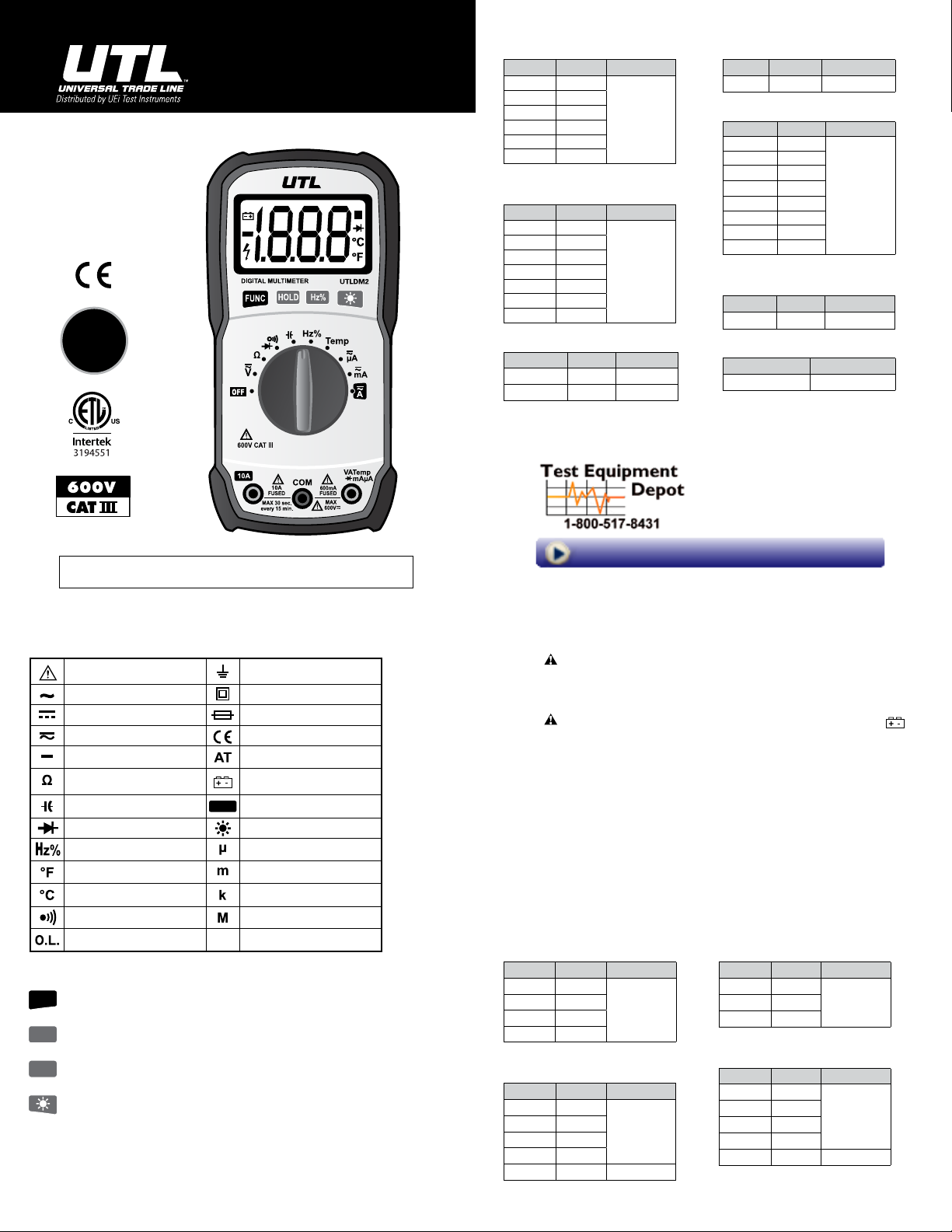
ELECTRIC SYMBOLS & METER ICONS
Important safety information Ground wire
AC (Alternating Current) Double insulation protection
DC (Direct Current) Fuse
AC or DC Complies with EU Regulations
Negative Polarity Auto Ranging
Resistance Low Battery
Capacitance
Diode Backlight
Frequency/Duty Ratio
Fahrenheit degrees Milli 10-3
Celsius degrees Kilo 103
Continuity
Overload: Range Exceeded
BUTTON OPERATION
Function selection key, switches measurement functions within each selector position by
FUNC
pressing “FUNC” key to toggle through each selection.
Data Hold key, press “HOLD” key; the reading will be locked and “HOLD” icon will display on
HOLD
display. Press “HOLD” key again to release.
Frequency / Duty Ratio selection key. Pressing this key can select Voltage / Frequency / Duty
Hz%
Ratio or Current / Frequency / Duty Ratio pending selector position.
Backlight key: Press “Backlight” key and hold for 2 seconds to turn on backlight.
Press again to turn off backlight.
AUTOMATIC POWER-OFF
In the measurement process, if there is no activity by the function key or function selection switch for
30 minutes, the meter will automatically shutdown (sleep state). Hold “FUNC” key to power on and the
automatic shutdown function will be cancelled.
HOLD
Data Hold
Micro 10-6
Mega 106
Visit us at www.TestEquipmentDepot.com
GENERAL MAINTENANCE
Warning
Regularly clean the meter case with damp cloth and a small amount of detergent. Do not use abrasives
or chemical solvents.
REPLACE BATTERIES & FUSES
Warning
appears on the display, replace the battery immediately. Turn off the meter and disconnect the test probe
from the meter before opening the back cover to replace batteries or fuses. Gain access to batteries and
fuse by using a screwdriver to loosen the battery cover screws on the back of the meter and removing
the cover.
GENERAL SPECIFICATIONS
▶ Operating Category: 600V CAT III, pollution
▶ Operating Elevation (< 2000 m)
▶ Operating Conditions: 0~40°C, <80% RH (do
▶ Storage Conditions: -10~60°C, <70% RH
▶ Temperature Coefficient: 1× Accuracy/°C
ELECTRICAL SPECIFICATIONS
DC VOLTAGE
Range Resolution Accuracy
600mV 0.1mV
6V 1mV
60V 10mV
600V 100mV
Overload protection: 600V RMS
DC CURRENT
Range Resolution Accuracy
600μA 0.1μA
6000μA 1μA
60mA 0.01mA
400mA 0.1mA
10A 0.01A ± (2.0% + 8 dgts)
mA, μA Overload Protection: 250V RMS
10A Overload Protection: 600V RMS
To avoid personal injury or damage to the meter, DO NOT wet the inner parts of the meter.
To avoid incorrect readings and possible electric shock or personal injury, when “ ”
degree: 2.
not use meter when temperature <10°C).
(remove the battery).
(<18°C or >28°C).
▶ Maximum Voltage between measurement end
and ground: 600V DC or 600V AC RMS.
▶ Fuse protection: mA Grade: fuse F600mA/600V
and 10A Grade: fuse F10A/600V
▶ Sampling rate: about 3 times/second.
▶ Display: 3 3/4 bits of digit LCD display.
▶ Power supply: 1 x 9V battery.
AC VOLTAGE
Range Resolution Accuracy
6V 1mV
± (0.5% + 2 dgts)
600V 100mV
Overload protection: 600V RMS
± (1.0% + 5 dgts)60V 10mV
AC CURRENT
Range Resolution Accuracy
600μA 0.1μA
± (1.0% + 5 dgts)
6000μA 1μA
60mA 0.01mA
600mA 0.1mA
10A 0.01A ± (2.0% + 8 dgts)
mA, μA Overload Protection: 250V RMS
10A Overload Protection: 600V RMS
± (1.0% + 5 dgts)
Page 2
WARNING
To avoid electric shock or personal injury, please read SAFETY INSTRUCTIONS, WARNINGS
and CAUTIONS carefully before use.
SAFETY INSTRUCTIONS: Read Before Use
The UTLDM2 digital multimeter has been designed according to International Electro Safety Standard IEC1010 (61010-1@IEC: 2001) concerning safety requirements for electronic measuring instruments and handheld digital multimeters. It meets the requirements for CAT III 600V of IEC1010 and pollution degree 2.
▶
Users should use the meter strictly according to the provisions of this manual. Otherwise, the warranty for the meter may become invalid.
The warnings in the user manual are used to remind users of possible danger or dangerous action.
▶
Cautions in the user manual are used to remind users of possible meter damage or condition or action
▶
of measured object.
WARNING
To avoid possible electric shock or personal injury as well as damage to the meter or measured objects,
please use the meter according to the following procedure methods:
Check the case before using the meter. Don’t use the meter when the case is damaged. Check to see
▶
if the case is cracked or lacks plastic parts. Please pay special attention to joint insulating layer.
Check to see whether test leads insulation damage or exposed bare metal. Check test lead continuity.
▶
If the test leads are damaged, please replace them with a new set before using the meter.
Measure known voltage with the meter to verify that the meter is working properly. If the meter is
▶
working abnormally, stop using it immediately. A protective device may be damaged. If there is any
doubt, please have the meter inspected by a qualified technician.
Do not test voltage exceeding rated voltage marked on the meter.
▶
When testing voltage exceeding 30v AC voltage RMS, 42v AC peak or 60v DC, be particularly careful
▶
to avoid electric shock.
When measuring, use correct jack, function and measuring range.
▶
Do not use the meter in explosive gas, vapor or dusty environments.
▶
When using the probe, fingers should be behind the probe protection device.
▶
When connecting circuits, please connect the common test line first, then connect the charged test
▶
line. When disconnecting circuits, please disconnect the charged test line first, then disconnect the
common test line.
Before measuring resistance, continuity, and diodes, first turn off power and discharge all high volt-
▶
age capacitors.
If the meter is not used in accordance with the instructions, the meter’s safety protection function
▶
may become invalid.
For all DC measurements, to avoid the risk of electric shock due to possible incorrect readings, please
▶
use AC function to verify the existence of any AC voltage. Then, select DC voltage measuring range
equal to or greater than the AC measuring range.
Before measuring current, check the meter fuse, shut off power to the circuit to be tested, then con-
▶
nect the meter and energize the circuit.
When opening the case (or part of the case), turn the meter off.
▶
When the battery low voltage indicator “ ” becomes lit, replace the battery at once. A low bat-
▶
tery will cause meter reading errors and may result in electric shock or personal injury.
Before opening case or battery cover, remove the test leads from the meter.
▶
When maintaining the meter, use replacement parts specified by the factory.
▶
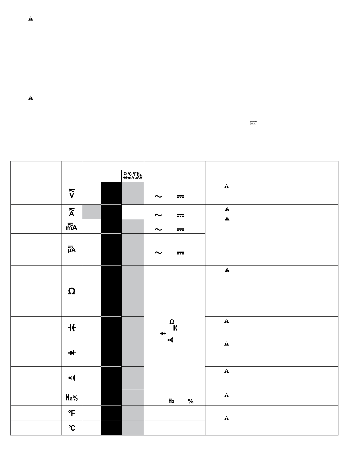
To
Measure
Rotate
Dial To
Connect Input Jacks
10A COM
AC/DC Voltage OPEN
AC/DC Current
> 400mA
AC/DC Current
< 400mA
AC/DC Current
< 400mA
Resistance
RED
LEAD
OPEN
OPEN
OPEN
Capacitance OPEN
Diode OPEN
Continuity OPEN
Frequency/
Duty Ratio
OPEN
Temperature Fahrenheit OPEN
Temperature Celsius OPEN
Test Equipment Depot - 800.517.8431 - 99 Washington Street Melrose, MA 02176
BLACK
LEAD
BLACK
LEAD
BLACK
LEAD
BLACK
LEAD
BLACK
LEAD
BLACK
LEAD
BLACK
LEAD
BLACK
LEAD
BLACK
LEAD
- Temp
LEAD
- Temp
LEAD
RED
LEAD
OPEN
RED
LEAD
RED
LEAD
RED
LEAD
RED
LEAD
RED
LEAD
RED
LEAD
RED
LEAD
+ Temp
LEAD
+ Temp
LEAD
FUNC
Features
Toggles between
) & DC ( ) Voltage
AC (
Toggles between
AC ( ) & DC ( ) Current
Toggles between
AC (
) & DC ( ) Current
Toggles between
) & DC ( ) Current
AC (
Toggles between
Resistance (
)
Capacitance ( )
Diode ( )
Continuity ( )
Toggles between
Frequency ( ) Duty ( )
TestEquipmentDepot.com
WARNING : Don’t measure any RMS voltage higher than 600V DC or AC, to prevent
• Display shows voltage polarity (connected with red test probe) when measuring DC
WARNING : Turn off the power to the circuit to be tested. Discharge all high voltage
WARNING
• Before measuring current, rst check the meter’s fuse. When measuring, use correct
• Turn off the circuit to be tested. The black test probe is connected to one end of
• Connecting test probe reversely make readings negative, but will not damage meter.
• Overload is indicated with “OL” on the display.
WARNING : When measuring resistance or circuit continuity, to avoid injury or meter
• The resistance measured on a circuit is usually different from the rated value of
• When measuring low resistance, to ensure accuracy, make a short circuit between the
• When there is no input (for example, open circuit), the display will show “OL”, which
WARNING : When measuring capacitance, to avoid injury or meter damage, turn off
• When measuring bulk capacitors with this meter, readings will stabilize after a few
WARNING : When measuring diodes, to avoid injury or meter damage, turn off the
• The meter will display the diode’s forward bias voltage value. If the test probe polarity
WARNING : When measuring resistance or circuit continuity, to avoid injury or meter
• If the measured circuit resistance is less than about 50Ω, the buzzer will sound
WARNING : Don’t input voltage higher than 60V DC or 30V AC in frequency/duty
WARNING : Don’t input voltage higher than 30V in temperature measurement posi-
Safety Warnings, Cautions and Operational Notes
injury or damage to meter and equipment.
voltage.
capacitors on the circuit to be tested.
: To prevent injury or damage to meter or equipment, do not make cur-
rent measurements if voltage exceeds 600V.
input end and function. When the test probe is inserted to the current input end, don’t
connect the other end of the test probe with any circuit in parallel.
disconnected circuit (low voltage relatively), and the red test probe is connected to the
other end of the disconnected circuit (high voltage relatively).
damage, turn off the power to circuit and discharge all capacitors.
resistance. This is because the test current of the meter will ow through all possible
channels between test probes.
test probes and read the resistance value of the short circuit. This resistance value
should be subtracted after measuring the resistance to be tested.
means that the measured value is out of range.
the power to the circuit to be measured discharge all capacitors.
seconds.
power to the circuit to be measured discharge all capacitors.
is reversed, the meter will display “OL”, which distinguishes the diode’s cathode and
anode.
damage, turn off the power to the circuit to be measured and discharge all capacitors.
continuously.
ratio measurement position, to prevent electric shock or meter damage
tion, to prevent electric shock or meter damage.
 Loading...