

Utility Solutions BREAK-SAFE USBS-15-2-PS, BREAK-SAFE USBS-38-2-PS, BREAK-SAFE USBS-15-1-PS, BREAK-SAFE USBS-27-1-PS, BREAK-SAFE USBS-27-2-PS Operation Manual
...
Phone (828)323-8914
Fax (828)323-8410
Email sales@utilitysolutionsinc.com
Web www.utilitysolutionsinc.com
101 33
rd
Street Drive SE · Hickory, NC 28602
Operation Manual
Contents
Components 2
Applications 3
Circuit Restrictions 3
Line and Tool Preparation 4
Operation 5
Resistance Test 7
Periodic Maintenance* 8
Storage 8
Warranty 8
BREAK-SAFE
®
Load Break & Pick-up Tool
USBS-15-1-PS
USBS-15-2-PS
USBS-27-1-PS
USBS-27-2-PS
USBS-38-1-PS
USBS-38-2-PS
USBS-46-1-PS
USBS-46-2-PS
B-01031 USBS
Manual (12-19-18)
Available Options:
H - Hard Case S - Soft Case
Copyright © 2018 Utility Solutions, Inc.
Second Generation Models Only.
For tools manufactured after
April 2014 and including
the Yellow Safety Lock.
PATENT NO. 6,078,008 Other Patents Pending

2
B-01031 USBS
Manual (12-19-18)
Components
Conductor
Hook
Load Pick-up Trigger
(located under Lock)
Conductor Bar
Load Break Ring
(should rotate freely)
Internal
Yellow Tube
Yellow
Safety
Lock
Brass
Contacts
Floating Head Duckbill Head

3
B-01031 USBS
Manual (12-19-18)
The BREAK-SAFE® is a jumper clamp that functions like a portable switch. It is designed
to operate on overhead distribution power lines in conjunction with an appropriately
rated and approved jumper cable.
There are three operating functions: load break, load pick-up and continuous current
duty. It is intended for temporary connections and should not be used in a permanent
capacity.
Floating Head models (USBS-XX-1-PS) are designed to be installed and removed from
overhead lines using appropriately rated and approved rubber gloves and personal
protective equipment. Duckbill Head models (USBS-XX-2-PS) are designed to be
installed and removed from overhead lines using an approved insulated hot stick.
All models require an approved insulated hot stick for the load break and load pick-up
operations.
Applications
Circuit Restrictions
The BREAK-SAFE® should not be used if the maximum voltage and/or amperage rating
of the tool can be exceeded. The BREAK-SAFE
®
is rated by maximum amperage and
voltage (kV). The table below details the specic ratings of the various BREAK-SAFE
®
models.
! !
DANGER
Contact with high voltage will cause death or grievous personal
injury to the operator. Only use this device in conjunction with
safe operating practices around energized lines and equipment.
Model
Maximum
System Voltage
Maximum
Current Rating
Minimum
Conductor Size
Maximum
Conductor Size
USBS-15-1-PS
15 kV
300 A
#6 Copper 954 ACSR
USBS-15-2-PS
USBS-27-1-PS
27 kV
USBS-27-2-PS
USBS-38-1-PS
38 kV
USBS-38-2-PS
USBS-46-1-PS
46 kV 200 A
USBS-46-2-PS
! !
WARNING
Carefully read and fully understand this manual prior to
operating, maintaining or testing this device. Improper
operation, handling or maintenance of this device can result
in death, grievous personal injury and or equipment damage.
! !
WARNING
Follow safe work procedures and practices when utilizing this
device. Failure to use this device in a safe manner can result
in death, grievous personal injury and or equipment damage.
! !
WARNING
ese instructions are not intended to replace or be a substitute
for proper safety training procedures. Failure to select the proper
tool in regards to minimum system requirements can result
in death, grievous personal injury and or equipment damage.
! !
WARNING
Always wear appropriately rated rubber gloves and personal
protective gear when utilizing this product to prevent electrocution.
Table 1

4
B-01031 USBS
Manual (12-19-18)
The BREAK-SAFE® has been tested to the full voltage and amperage rating for nominal
power factors of 70%-80% for both load break and load make applications. However,
the tool is rated by system voltages. For example, a 15 kV tool on a 15 kV system will
usually experience voltages of 15 kV / √3 or about 8.6 kV. It is at these actual (√3 ) system
voltage levels that the tool is rated for line charging and cable charging applications.
The BREAK-SAFE
®
USBS-15-1-PS and USBS-15-2-PS models have been tested at full
15 kV. This does not mean the tool is rated for phase to ground applications of a 27 kV
system. Use a 15 kV BREAK-SAFE
®
for 15 kV system voltages and below. Use a 27 kV
BREAK-SAFE
®
for 27 kV system voltages and below. Use a 38 kV BREAK-SAFE
®
for 38
kV system voltages and below. Use a 46 kV BREAK-SAFE
®
for 46 kV system voltages
and below.
The tool is designed to be used on three phase systems, but only on a single phase at a
time. Typical three phase applications require three separate tools.
Outlined below are some circuit restrictions known to exist:
• Do not utilize the BREAK-SAFE
®
tool in situations where ferroresonance
can produce over-voltage situations. An example of this involves switching
unloaded transformers that are delta-connected three phase and wyeconnected three phase with primary neutral ungrounded.
• The tool should never be used in phase-to-phase applications.
• Do not utilize the BREAK-SAFE
®
to switch unloaded transformers.
• Do not utilize the BREAK-SAFE
®
to switch capacitor banks.
! !
WARNING
When working with the BREAK-SAFE® always assume the tool is
energized at all times. Never consider the tool body as rated insulation.
! !
WARNING
e BREAK-SAFE® is NOT a fuse. It should be
used in a temporary capacity only.
! !
WARNING
Carefully inspect the tool prior to each use. Damaged components
can result in personal injury and or equipment damage.
Line and Tool Preparation
1. Do not exceed the maximum voltage or amperage rating of the tool (TABLE 1).
2. Insulate the pole and conductor as required by the supervising utility safety practices.
3. Clean the conductor at each location where the BREAK-SAFE
®
and jumper cable will
be attached. Clean and inspect the conductor bar before attaching a jumper cable.
4. If the BREAK-SAFE
®
is equipped with a duckbill head (USBS-XX-2-PS) ensure that all
attachment fasteners are tight and secure.
! !
WARNING
e BREAK-SAFE® is not waterproof. Do not use the BREAK-SAFE® in
wet conditions. If inclement weather is expected aer installation, cover
tool with an approved insulating rubber blanket.
! !
WARNING
Only trained and qualied personnel should operate,
inspect and maintain this equipment.
! !
WARNING
Always remove the BREAK-SAFE® from the circuit, or remove the
jumper attached to the conductor bar, aer each load break operation.
e BREAK-SAFE
®
is not rated insulation
nor is it considered a “visible gap”.

5
B-01031 USBS
Manual (12-19-18)
Operation
Prepare the Tool for use
1. Refer to the laminated Field Inspection Procedure card before each use.
2. Place the BREAK-SAFE
®
in the UNLOCK Position (FIGURE 1) by lifting the Yellow
Safety Lock to gain access to the Load Break Ring.
3. Pull the Load Break Ring until the tool locks in the open tool position (the internal
yellow tube is visible).
4. Lower the Yellow Safety Lock into the LOCK OPEN position (FIGURE 2) to prevent
an accidental load pick-up operation.
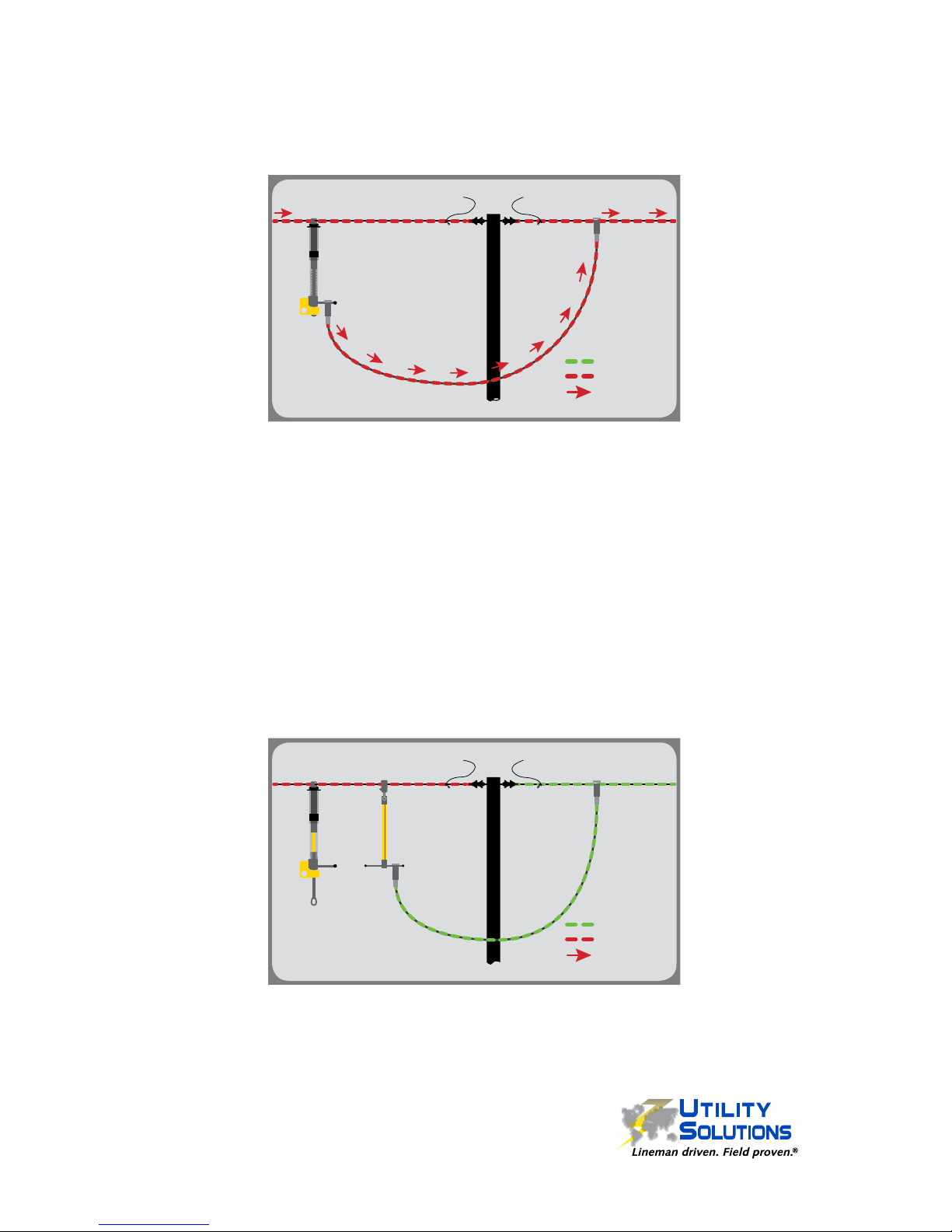
Install the Tool and Jumper Cable
5. Securely attach the BREAK-SAFE
®
in the LOCK OPEN position to the “SOURCE
SIDE” (FIGURE 3) of the circuit using standard utility safety practices and procedures.
6. Securely attach one end of an appropriately rated and approved jumper cable to the
“LOAD SIDE” of the circuit (FIGURE 3) using standard utility safety practices and
procedures.
7. Securely attach the opposite end of an appropriately rated and approved jumper
cable to the Conductor Bar of the BREAK-SAFE
®
(FIGURE 3).
Perform Load Pick-up Operation
8. Visually check connections and conrm placement of the tool and
jumper cable on the circuit before performing the Load Pick-up
operation (FIGURE 3).
9. The Load Pick-up operation must be done using an approved
insulated hot stick and NEVER by hand.
10. Using an approved insulated hot stick, lift the Yellow Safety Lock
into the UNLOCK position (FIGURE 1) to gain access to the Load
Pick-up Trigger.
11. Using an approved insulated hot stick, exert a steady downward
movement on the Load Pick-up Trigger. The Load Break Ring
Assembly will retract forcefully into the Clear Tube Assembly
energizing the circuit. Push up on the Load Break Ring with the
hot stick to verify the brass contacts are fully seated (FIGURE 4).
12. Immediately lower the Yellow Safety Lock into the LOCK CLOSE
position (FIGURE 5) to prevent an accidental load break operation.
Figure 4
Figure 1
“SOURCE”
SIDE
“LOAD”
SIDE
NON-ENERGIZED
ENERGIZED
CURRENT FLOW
Figure 3
Figure 2
Figure 5
6
B-01031 USBS
Manual (12-19-18)
Temporary Circuit Established
A temporary or parallel circuit has now been established. The permanent circuit can be
disconnected or cut following standard safety practices and procedures while maintenance
or other activities are performed (FIGURE 6). Note: The BREAK-SAFE
®
is a temporary
device and is not meant for long term use. The BREAK-SAFE® is NOT a fuse.
Perform Load Break Operation
13. Using an approved insulated hot stick, lift the Yellow Safety Lock into the UNLOCK
position (FIGURE 1) to gain access to the Load Break Ring.
14. Using an approved insulated hot stick, push up on the Load Break Ring to verify the
tool has been properly reset (FIGURE 4).
15. With one steady motion, pull down rmly on the Load Break Ring using an approved
insulated hot stick until the tool locks in the open position. Do not stop or hesitate
while pulling.
16. Immediately lower the Yellow Safety Lock into the LOCK OPEN position (FIGURE 2)
to prevent an accidental Load Pick-up operation.
17. Verify there is NO VOLTAGE and/or NO AMPERAGE present on the BREAK-SAFE
®
and the jumper cable.
18. If the SOURCE SIDE circuit is to remain energized while work is done, move the
jumper cable to the conductor bar of a Utility Solutions Jumper-T (USJT-001/2) or
equivalent device (FIGURE 7). This will create a visible gap using rated insulation.
19. To re-energize the temporary circuit, repeat the procedure beginning at step #7.
20. If the temporary circuit will not be re-energized, the BREAK-SAFE
®
and the jumper
cable may be safely removed from the permanent circuit.
21. The BREAK-SAFE
®
should be stored in the LOCK CLOSE position (FIGURE 5).
“SOURCE”
SIDE
“LOAD”
SIDE
NON-ENERGIZED
ENERGIZED
CURRENT FLOW
Figure 6
“SOURCE”
SIDE
“LOAD”
SIDE
NON-ENERGIZED
ENERGIZED
CURRENT FLOW
Figure 7

7
B-01031 USBS
Manual (12-19-18)
An optional Resistance Test may be performed in between scheduled maintainance.
This test DOES NOT replace scheduled maintenance or extend the time between
scheduled maintenance.
This test is performed using the Utility Solutions USGT-600 Grounds Tester w/ REACH
Technology or equivalent device. Refer to the testers’ instruction manual for proper set-
up procedures.
1. The BREAK-SAFE
®
should be in
the closed position and RESET
with the external brass contacts
fully seated.
2. Connect the BREAK-SAFE
®
Conductor Hook to a Current
Output Post on the Grounds
Tester (A). Position and support
the BREAK-SAFE® so the
weight of the tool does not apply
sideways force on the Current
Output post (a small block of
wood should sufce).
3. Connect a standard Mechanical
Jumper (minimum 6 feet, 1/0
AWG, 300 AMP) to the other
Current Output Posts of
the Grounds Tester and the
conductor bar of the BREAKSAFE
®
(B).
4. Put the Grounds Tester in
REACH mode.
5. Turn on the Grounds Tester and
adjust the Current Control Knob
to energize to 300 AMPS.
6. Using the red and black Jumper
Leads on the Grounds Tester,
measure the voltage on the
BREAK-SAFE
®
between the
lower jaw of the Conductor Hook
(A) and the Parking Stand (B) .
7. Voltage drop should not exceed 0.220 volts. If the voltage displayed exceeds 0.220
volts the tool should be removed from service. Maintenance should be performed by
the factory or by trained and certied personnel.
A
B
Resistance Test

8
B-01031 USBS
Manual (12-19-18)
Periodic Maintenance
A two year maintenance schedule is recommended for all 2nd generation models
of the BREAK-SAFE
®
Load Break & Pick-up Tool. A shorter maintenance schedule is
recommended for frequently used tools or tools operated at or near their maximum ratings.
Maintenance should be performed by the factory or by trained and certied personnel.
The maintenance decal is located near the product decal.
MAINTENANCE REMINDER style decals indicate the date of manufacture or date of last
service. Service is recommended 2 years after the date shown.
MAINTENANCE DUE style decals indicate the date of next service. Service is
recommended on or before the date shown.
MAINTENANCE
REMINDER
RECOMMENDED MAINTENANCE DUE
TWO YEARS FROM DATE SHOWN
(SEE INSTRUCTION MANUAL FOR DETAILS)
121110987
654321
MONTH
YEAR
2014
2015
2016
2017
B-000970
Storage
The BREAK-SAFE® should be stored in a clean, dry place. Damp and/or high humidity
environments should be avoided.
The BREAK-SAFE
®
should be stored in the LOCK CLOSE position
(internal yellow tube will not be visible). Utility Solutions recommends
storing the BREAK-SAFE
®
in a soft case (USBS-XX-SOFTCASE) or hard
case (USBS-XX-HARDCASE).
Warranty
Utility Solutions warrants the BREAK-SAFE® Load Break & Pick-up Tool for any defects
in manufacturing for the period of one year. If the tool is returned within that time period,
Utility Solutions will repair or replace the tool free of charge.
MAINTENANCE
DUE ON:
1211
10
9
8
7
6
5
4
3
21
MONTH
2021
B-01543
 Loading...