

Page 1
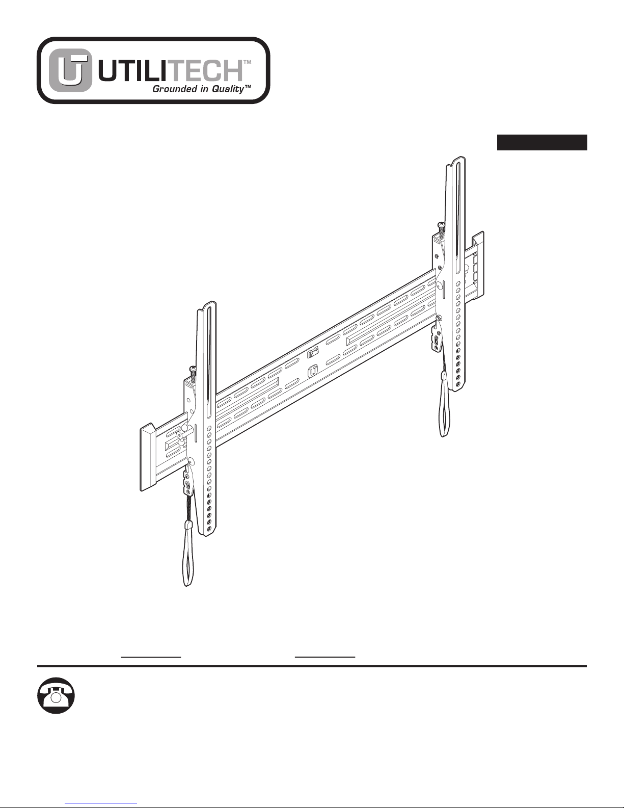
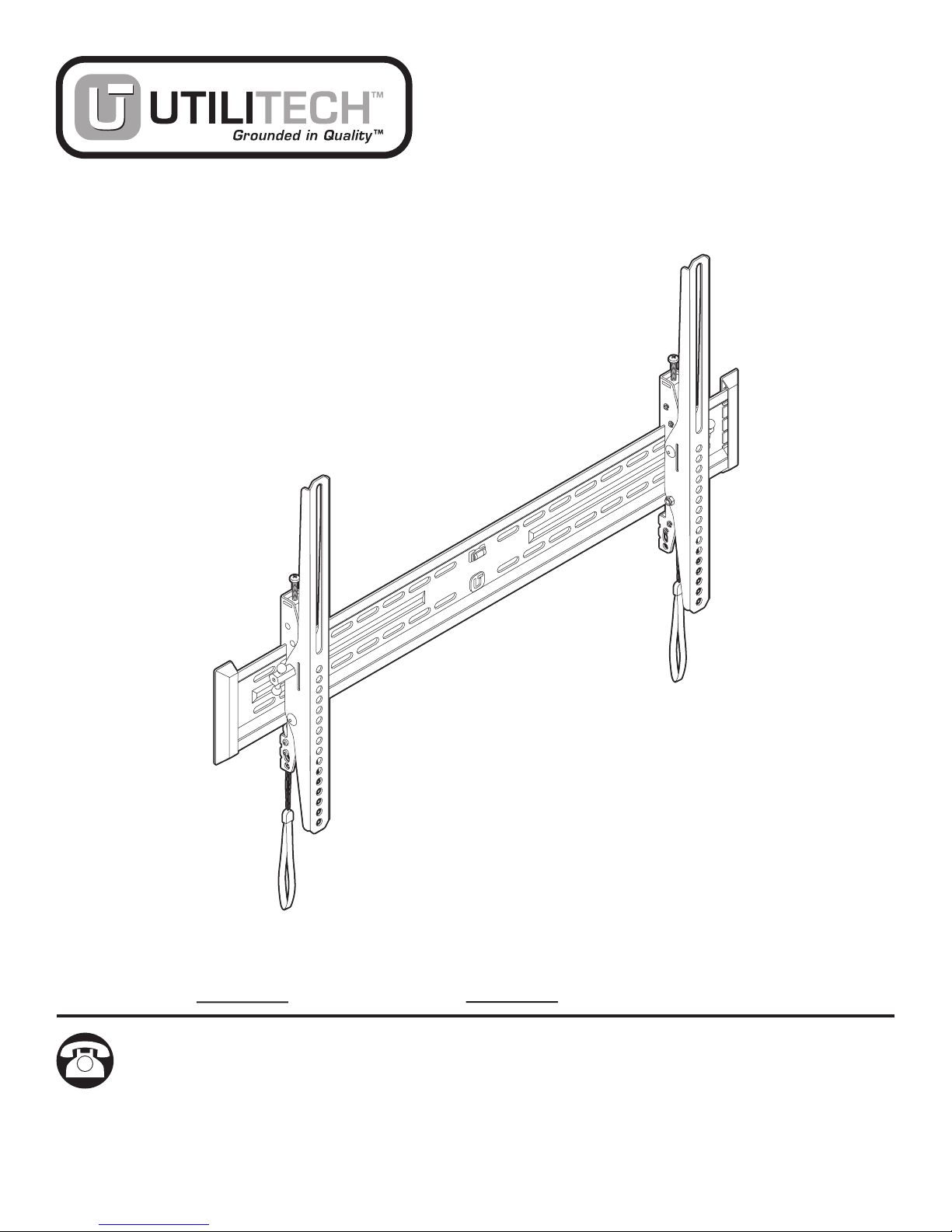
ITEM #1143421
TV WALL MOUNT
WITH HEIGHT ADJUST
MODEL #UT175TP
Español p. 15
ATTACH YOUR RECEIPT HERE
Serial Number
Questions, problems, missing parts? Before returning to your retailer, call our customer
service department at 1-602-674-1000, 8 a.m. - 5 p.m., MST, Monday - Friday.
P18471
Purchase Date
1
Page 2
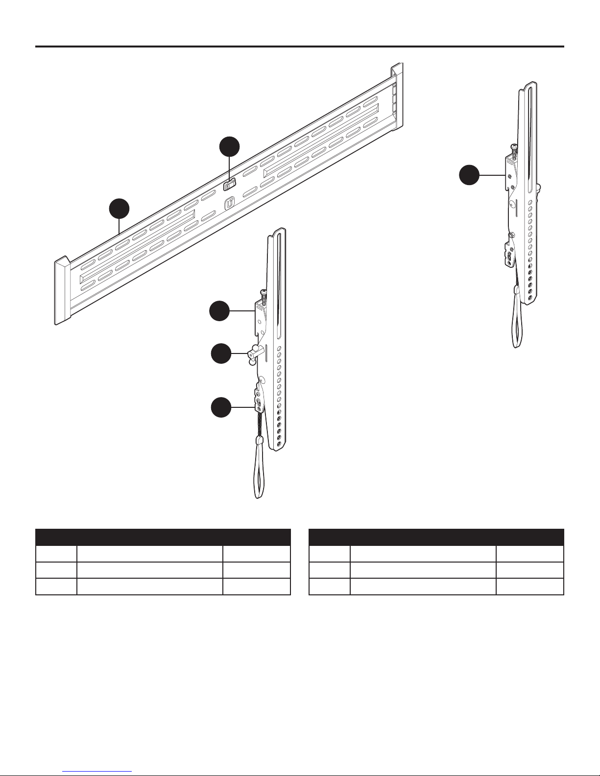
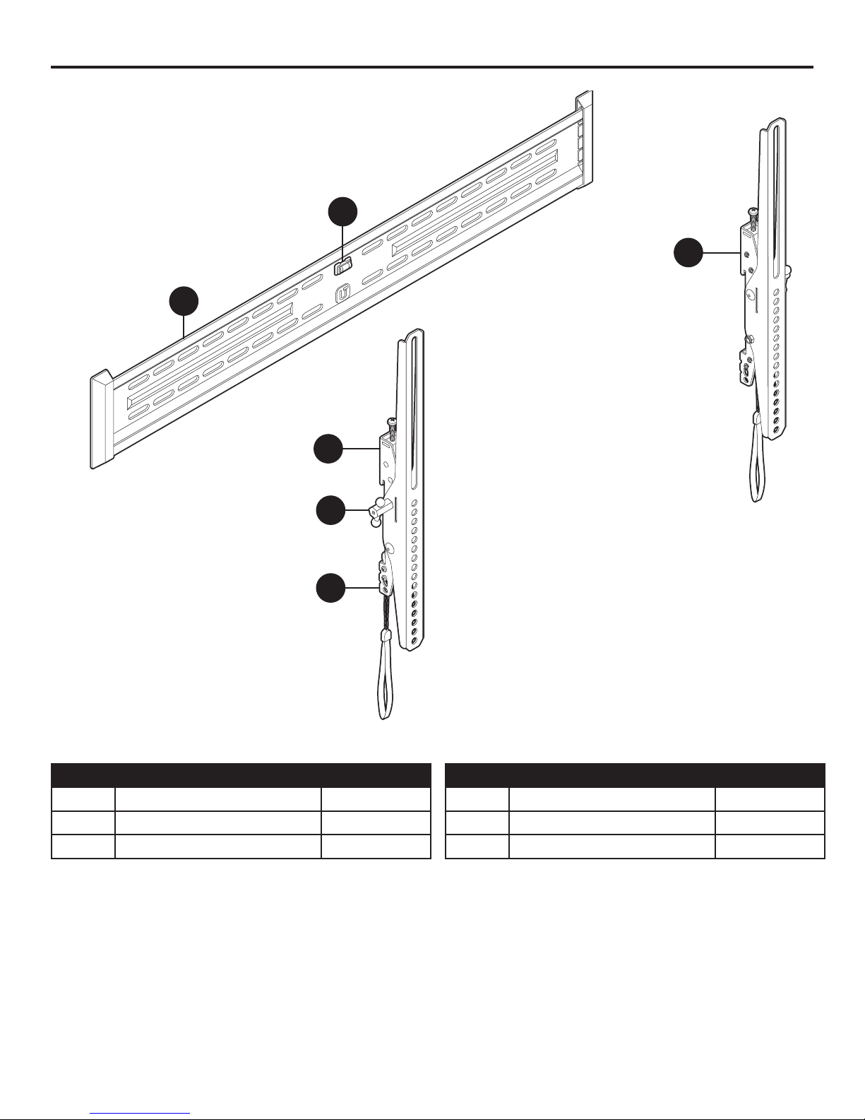
PACKAGE CONTENTS
A
B
D
C
E
F
PART DESCRIPTION QUANTITY
A Wall plate 1
B Bubble level 1
C Left vertical rail 1
PART DESCRIPTION QUANTITY
D Right vertical rail 1
E Tilt lever 2
F Spring lock 2
2
Page 3
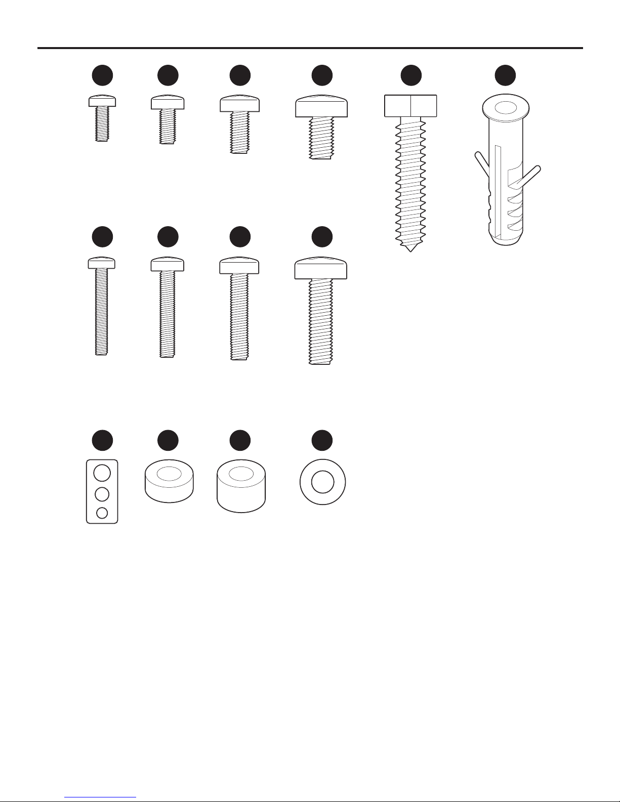
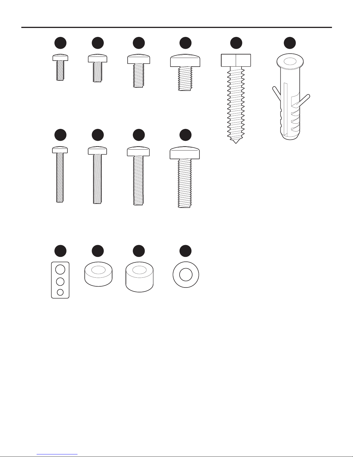
HARDWARE CONTENTS (shown actual size)
AA
M4 x 12
Screw
Qty. 4
EE
BB
M5 x 12
Screw
Qty. 4
FF
CC
M6 x 15
Screw
Qty. 4
GG
DD
M8 x 15
Screw
Qty. 4
HH
II
8 mm Lag bolt
Qty. 4
JJ
Anchor
Qty. 4
M4 x 30
Screw
Qty. 4
KK
Square
washer
Qty. 4
M5 x 30
Screw
Qty. 4
LL
5 mm
Spacer
Qty. 4
M6 x 30
Screw
Qty. 4
MM
10 mm
Spacer
Qty. 4
M8 x 30
Screw
Qty. 4
NN
Steel
washer
Qty. 12
3
Page 4
SAFETY INFORMATION
Please read and understand this entire manual before attempting to assemble, operate or install the
product.
WARNING
• FAILURE TO READ, THOROUGHLY UNDERSTAND, AND FOLLOW ALL INSTRUCTIONS CAN
RESULT IN SERIOUS PERSONAL INJURY, DAMAGE TO PERSONAL PROPERTY, OR VOIDING
OF FACTORY WARRANTY.
• Do not attempt to install or assemble this product if the product or hardware is damaged or missing.
The included hardware is designed for use on vertical walls constructed of wood studs or solid
concrete. A wood stud wall is dened as consisting of a minimum of 2x4 wooden studs (2 in. wide
by 4 in. deep) with a maximum of 5/8 in. drywall. The included hardware is not designed for use with
metal studs or cinderblock walls. If you are uncertain about the construction of your wall, please
consult a qualied contractor or installer for assistance. For safe installation, the wall selected for
mounting must support 4 times the weight of the total load. If not, the surface must be reinforced
to meet this standard. The installer is responsible for verifying that the wall structure and hardware
used in any installation method will safely support the total load.
CAUTION
• The maximum loading weight is 175 lbs. Use with products heavier than the maximum weight
indicated may result in instability and possible personal injury.
• Max screen size: 90 in.
KEEP THESE INSTRUCTIONS FOR FUTURE REFERENCE.
PREPARATION
Before beginning assembly of product, make sure all parts are present. Compare parts with package
contents list and hardware contents list. If any part is missing or damaged, do not attempt to
assemble the product.
Estimated Assembly Time: 30 minutes
Tools Required for Assembly (not included): Drill with 7/32 in. and 3/8 in. drill bits, stud nder, socket
wrench, pencil, Phillips screwdriver, hammer, hex wrench.
4
Page 5
ASSEMBLY INSTRUCTIONS
Screw
Qty. 4
M5 x 12
Screw
Qty. 4
M6 x 15
Screw
Qty. 4
M8 x 15
Screw
Qty. 4
8 mm Lag bolt
Qty. 4
Anchor
Qty. 4
Screw
Qty. 4
EE
M5 x 30
Screw
Qty. 4
FF
M6 x 30
Screw
Qty. 4
GG
M8 x 30
Screw
Qty. 4
HH
Square
washer
Qty. 4
KK
5 mm
Spacer
Qty. 4
LL
10 mm
Spacer
Qty. 4
MM
Steel
washer
Qty. 12
NN
washer
Qty. 4
5 mm
Spacer
Qty. 4
10 mm
Spacer
Qty. 4
Steel
washer
Qty. 12
M5 x 12
Screw
Qty. 4
M6 x 15
Screw
Qty. 4
M8 x 15
Screw
Qty. 4
8 mm Lag bolt
Qty. 4
Anchor
Qty. 4
M5 x 30
Screw
Qty. 4
FF
M6 x 30
Screw
Qty. 4
GG
M8 x 30
Screw
Qty. 4
HH
5 mm
Spacer
Qty. 4
LL
10 mm
Spacer
Qty. 4
MM
Steel
washer
Qty. 12
NN
M6 x 15
Screw
Qty. 4
M8 x 15
Screw
Qty. 4
8 mm Lag bolt
Qty. 4
Anchor
Qty. 4
M6 x 30
Screw
Qty. 4
GG
M8 x 30
Screw
Qty. 4
HH
10 mm
Spacer
Qty. 4
MM
Steel
washer
Qty. 12
NN
M8 x 15
Screw
Qty. 4
8 mm Lag bolt
Qty. 4
Anchor
Qty. 4
M8 x 30
Screw
Qty. 4
HH
Steel
washer
Qty. 12
NN
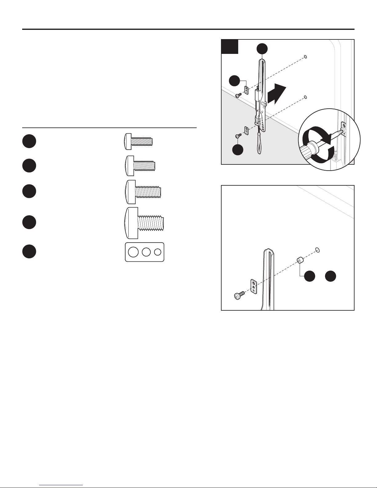
1a. For at back at panel: Attach left vertical
rail (C) with two square washers (KK) and two
screws (*). Repeat for right vertical rail (D).
* Note: Rails can be attached with M4 x 12 screws (AA),
M5 x 12 screws (BB), M6 x 15 screws (CC), or M8 x 15
screws (DD) depending on your TV.
Hardware Used
AA
BB
CC
DD
M4 x 12 Screw
M5 x 12 Screw
M6 x 15 Screw
M8 x 15 Screw
x 4
x 4
x 4
x 4
1a
KK
C
1
2
*
Tip: 5 mm spacers (LL) and/or
10 mm spacers (MM) can also be
used to provide clearance for cables
and connectors.
KK
Square washer
x 4
LL or
MM
5
Page 6
ASSEMBLY INSTRUCTIONS
8 mm Lag bolt
Qty. 4
Anchor
Qty. 4
Screw
Qty. 4
M5 x 30
Screw
Qty. 4
M6 x 30
Screw
Qty. 4
M8 x 30
Screw
Qty. 4
washer
Qty. 4
KK
5 mm
Spacer
Qty. 4
LL
10 mm
Spacer
Qty. 4
MM
Steel
washer
Qty. 12
NN
washer
Qty. 4
5 mm
Spacer
Qty. 4
10 mm
Spacer
Qty. 4
Steel
washer
Qty. 12
8 mm Lag bolt
Qty. 4
Anchor
Qty. 4
Screw
Qty. 4
M6 x 30
Screw
Qty. 4
M8 x 30
Screw
Qty. 4
5 mm
Spacer
Qty. 4
LL
10 mm
Spacer
Qty. 4
MM
Steel
washer
Qty. 12
NN
8 mm Lag bolt
Qty. 4
Anchor
Qty. 4
M6 x 30
Screw
Qty. 4
M8 x 30
Screw
Qty. 4
10 mm
Spacer
Qty. 4
MM
Steel
washer
Qty. 12
NN
8 mm Lag bolt
Qty. 4
Anchor
Qty. 4
M8 x 30
Screw
Qty. 4
Steel
washer
Qty. 12
NN
5 mm
Spacer
Qty. 4
10 mm
Spacer
Qty. 4
Steel
washer
Qty. 12
10 mm
Spacer
Qty. 4
Steel
washer
Qty. 12
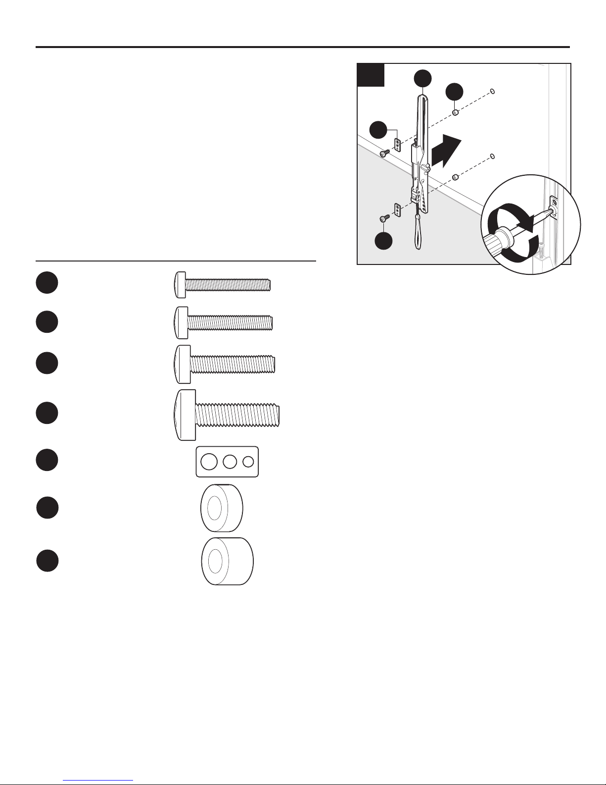
1b. For curved back at panel: Secure vertical
rail (C) with four spacers (*), two square
washers (KK), and two screws (**). Repeat for
vertical rail (D).
* Note: 5 mm spacer (LL) or 10 mm spacer (MM) can
be used depending on your TV.
** Note: Rails can be attached with M4 x 30 screws (EE),
M5 x 30 screws (FF), M6 x 30 screws (GG), or
M8 x 30 screws (HH) depending on your TV.
Hardware Used
EE
FF
M4 x 30 Screw
M5 x 30 Screw
x 4
x 4
1b
KK
C
*
1
2
**
GG
HH
KK
M6 x 30 Screw
M8 x 30 Screw
Square washer
LL
5 mm Spacer
MM
10 mm Spacer
x 4
x 4
x 4
x 4
x 4
6
Page 7
ASSEMBLY INSTRUCTIONS
5 mm
Spacer
Qty. 4
Phillips
screw
Qty. 8
Mounting arm screw
(preassembled to
Mounting arm (A))
Qty. 2
10 mm
Spacer
Qty. 4
Steel
washer
Qty. 8
Phillips
screw
Qty. 8
Mounting arm screw
(preassembled to
Mounting arm (A))
Qty. 2
10 mm
Spacer
Qty. 4
Steel
washer
Qty. 8
Phillips
screw
Qty. 8
Mounting arm screw
(preassembled to
Mounting arm (A))
Qty. 2
Steel
washer
Qty. 8
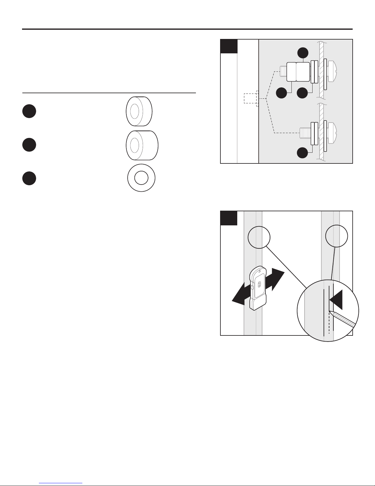
2. If screws are too long, additional 5 mm spacers (LL),
10 mm spacers (MM), and steel washers (NN) may
be needed.
Hardware Used
x 4
LL
MM
NN
Wood Stud Installation
Note: For concrete, proceed to step 7.
5 mm Spacer
x 4
10 mm Spacer
x 8
Steel washer
2
MM
TV
NNLL
NN
3
3. Use a stud nder (not included) to locate wood
studs. Mark the edge and center locations.
1
1
2
7
Page 8
ASSEMBLY INSTRUCTIONS
2
Qty. 4
Anchor
Qty. 4
Steel
washer
Qty. 12
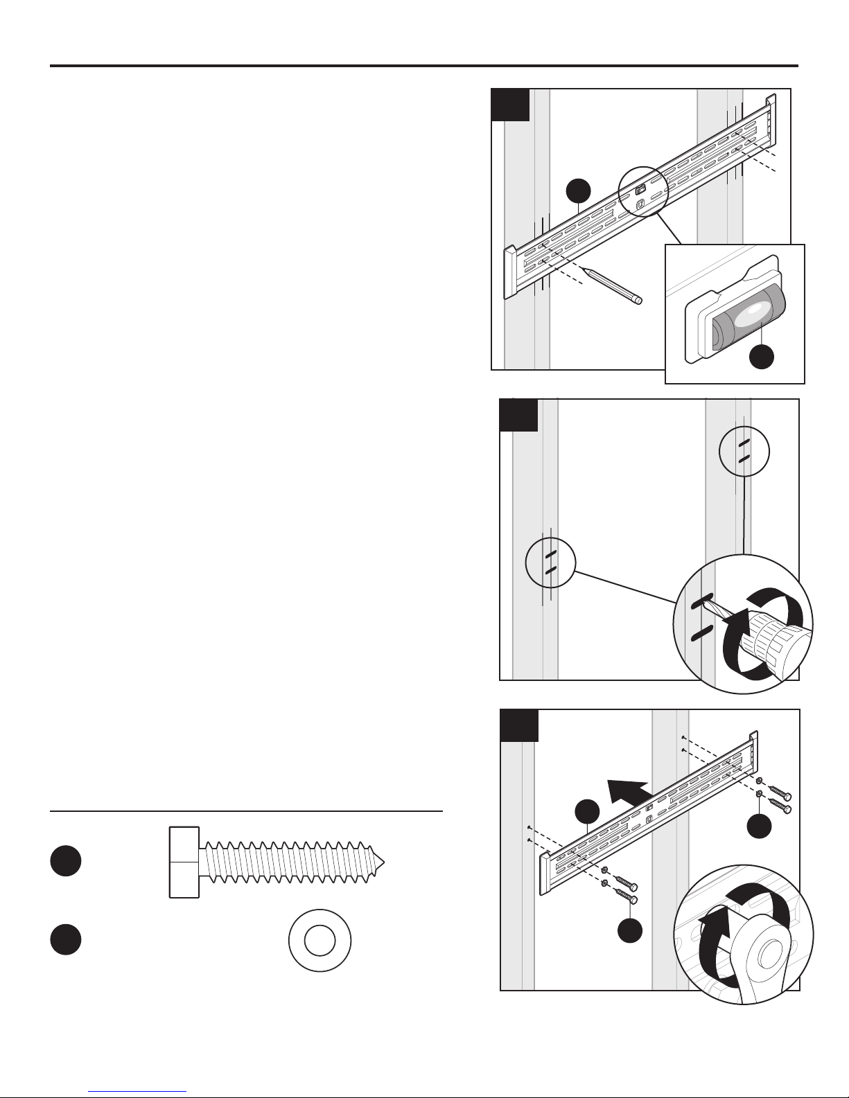
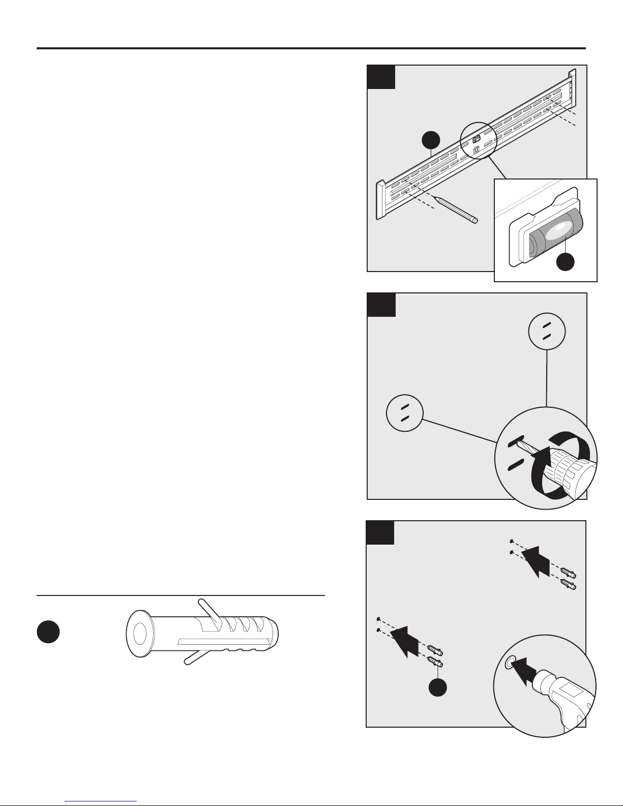
4. Use wall plate (A) to mark four mounting hole
locations.
Note: Use bubble level (B) to level wall plate (A).
5. Drill four 7/32 in. pilot holes 2-1/3 in. (60 mm)
deep at the marked locations for the mounting
holes.
4
A
B
5
6. Mount wall plate (A) using four steel
washers (NN) and four 8 mm lag bolts (II) with a
1/2 in. socket wrench (not included).
Hardware Used
8 mm
II
Lag bolt
NN
Steel washer
x 4
x 4
6
1
A
NN
II
8
Page 9
ASSEMBLY INSTRUCTIONS
2
Anchor
Qty. 4
Concrete Installation
7. Use wall plate (A) to mark four mounting hole
locations.
Note: Use bubble level (B) to level wall plate (A).
8. Drill four 3/8 in. pilot holes 2-3/4 in. (70 mm)
deep at the marked locations for the mounting
holes.
7
A
B
8
9. Insert anchors (JJ) into holes. Tap with hammer
(not included) if necessary.
Hardware Used
JJ
Anchor
x 4
9
1
1
JJ
9
Page 10
ASSEMBLY INSTRUCTIONS
2
Qty. 4
Anchor
Qty. 4
Steel
washer
Qty. 12
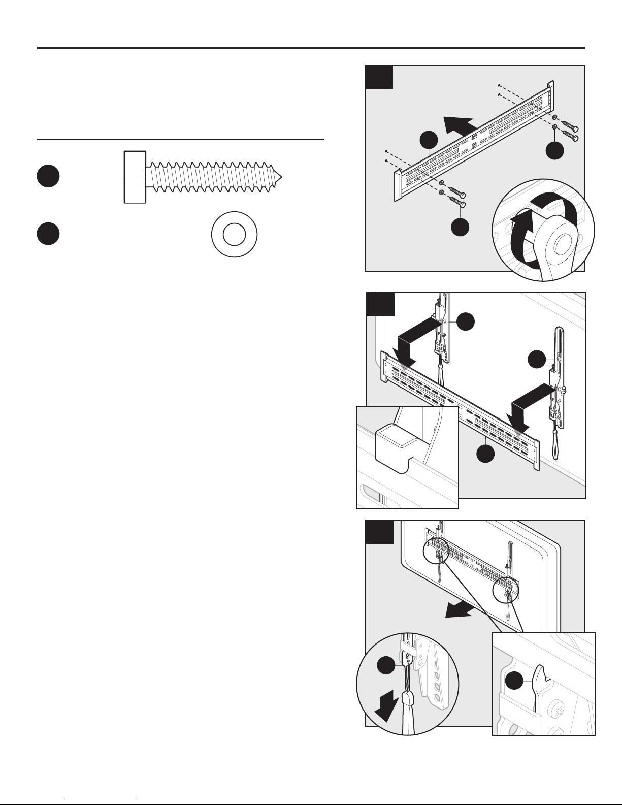
10. Mount wall plate (A) using four steel
washers (NN) and four 8 mm lag bolts (II) with
a 1/2 in. socket wrench (not included).
Hardware Used
8 mm
II
Lag bolt
NN
Final Installation
11. Hang right vertical rail (C) and left vertical
rail (D) onto wall plate (A).
Steel washer
x 4
x 4
10
1
A
NN
II
11
D
C
12. Pull spring locks (F) down and push bottom
of panel toward wall. Release spring locks (F)
when panel is secure.
A
12
2
F
F
1
10
Page 11
ASSEMBLY INSTRUCTIONS
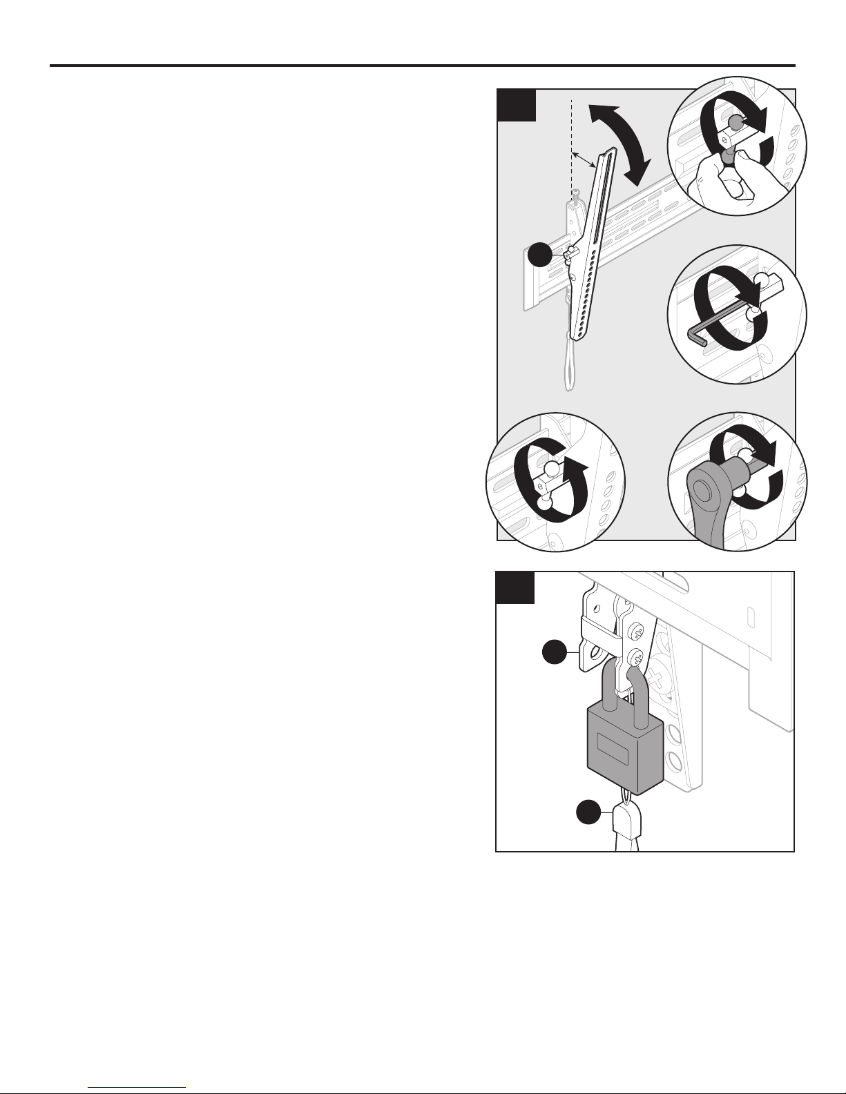
13. To adjust tilt, loosen both tilt levers (E) and
move panel to desired position. Tighten both tilt
levers (E) to hold desired tilt.
Note: For clarity, illustration is shown with panel
removed.
13
-3°–12°
E
2
2
3
or
3
5 mm
or
3
1
Additional Security (Optional)
14. Secure panel with 7 mm pad lock (not included)
for theft security.
1/2 in.
14
C/D
F
11
Page 12
ASSEMBLY INSTRUCTIONS
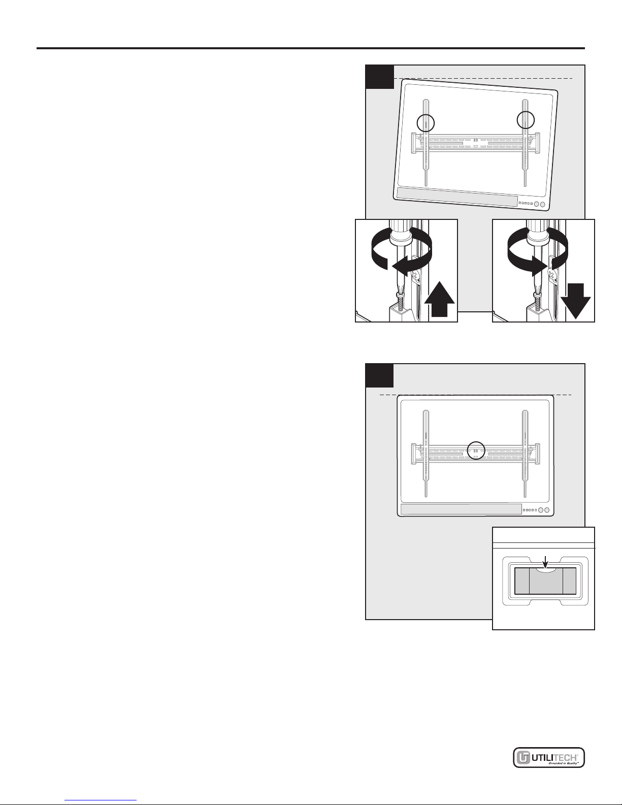
Leveling
1. Adjust the screws on the vertical rails to level
the at panel.
1
2. Use the built in level to gauge the adjustment.
Note: bubble in level will be centered when correct.
2
Lowes.com
12
Page 13

WARRANTY
This product is covered against defects in materials and workmanship for 5 years. The manufacturer
will repair or replace the defective component or product, at its sole discretion. Failure to follow
product care instructions from the manufacturer will void the warranty.
To obtain warranty service, contact customer service at 1-602-674-1000. You must supply a copy of
your original receipt. If your product must be shipped for inspection, you will be responsible for the
shipping charges. Replacement product shipped to you will be returned freight pre-paid.
The manufacturer disclaims any liability for modications, improper installations, installations over
the specied weight range, or failure to follow care instructions provided by the manufacturer. To
the maximum extent permitted by law, the manufacturer disclaims any other warranties, expressed
or implied, including warranties of tness for a particular purpose and warranties of merchantability.
The manufacturer will not be liable for any damages arising out of the use of, or inability to use, this
product.
This warranty gives you specic legal rights, and you may also have other rights which vary from
state to state.
Specications are subject to change without prior notice.
Lowes.com
13
Page 14

Printed in China
Lowes.com
14
Page 15
ARTÍCULO #1143421
SISTEMA DE MONTAJE DE
TELEVISOR PARA PARED
CON AJUSTE DE ALTURA
MODELO #UT175TP
ADJUNTE SU RECIBO AQUÍ
Número de serie
¿Preguntas, problemas, piezas faltantes? Antes de volver a la tienda, llame a nuestro
Departamento de Servicio al Cliente al 1-602-674-1000, de lunes a viernes de 8 a.m. a
5 p.m., hora estándar de la Montaña.
Fecha de compra
15
Page 16
CONTENIDO DEL PAQUETE
A
B
D
C
E
F
PIEZA DESCRIPCIÓN CANTIDAD
A Placa para pared 1
B Nivel de burbuja 1
C Riel vertical izquierdo 1
PIEZA DESCRIPCIÓN CANTIDAD
D Riel vertical derecho 1
E Palanca inclinable 2
F Resorte de bloqueo 2
16
Page 17
ADITAMENTOS (se muestran en tamaño real)
AA
Tornillo
M4 x 12
Cant. 4
EE
BB
Tornillo
M5 x 12
Cant. 4
FF
CC
Tornillo
M6 x 15
Cant. 4
GG
DD
Tornillo
M8 x 15
Cant. 4
HH
II
Tirafondo de 8 mm
Cant. 4
JJ
Ancla de
expansión
Cant. 4
Tornillo
M4 x 30
Cant. 4
KK
Arandela
cuadrada
Cant. 4
Tornillo
M5 x 30
Cant. 4
LL
Espaciador
de 5 mm
Cant. 4
Tornillo
M6 x 30
Cant. 4
MM
Espaciador
de 10 mm
Cant. 4
Tornillo
M8 x 30
Cant. 4
NN
Arandela
de acero
Cant. 12
17
Page 18
INFORMACIÓN DE SEGURIDAD
Lea y comprenda completamente este manual antes de intentar ensamblar, usar o instalar el
producto.
ADVERTENCIA
• ASEGÚRESE DE LEER, COMPRENDER Y SEGUIR LAS INSTRUCCIONES ADECUADAMENTE;
DE LO CONTRARIO, PUEDEN OCASIONARSE LESIONES PERSONALES GRAVES, DAÑOS A
LA PROPIEDAD O ANULACIÓN DE LA GARANTÍA DE FÁBRICA.
• No intente instalar o ensamblar el producto si faltan algunas piezas o los aditamentos están
dañados. Los aditamentos incluidos están diseñados para utilizarse en paredes verticales
construidas en montantes de madera o de concreto sólido. Una pared de montantes de madera
suele estar compuesta por vigas de madera de 2x4 (2 pulg. de ancho por 4 pulg. de profundidad),
como mínimo, con un panel de yeso de 5/8 pulg., como máximo. Los aditamentos incluidos no
están diseñados para utilizarse en paredes con vigas de metal o de bloque de hormigón. Si no
está seguro acerca de la construcción de su pared, comuníquese con un contratista o instalador
calicado para obtener ayuda. Para una instalación segura, la pared en la cual colocará el montaje
debe soportar 4 veces el peso de la carga total. De lo contrario, la supercie se debe reforzar para
alcanzar dicho estándar. El instalador es el responsable de vericar que la estructura de la pared
y el aditamento utilizado a través de cualquier método de instalación soportarán la carga total de
forma segura.
PRECAUCIÓN
• El peso máximo de carga es de 79,37 kg. El uso con productos más pesados que el máximo
indicado puede ocasionar inestabilidad y posibles lesiones.
• Tamaño máximo de la pantalla: 228,6 cm.
CONSERVE ESTAS INSTRUCCIONES PARA REFERENCIA FUTURA.
PREPARACIÓN
Antes de comenzar a ensamblar el producto, asegúrese de tener todas las piezas. Compare
las piezas con la lista del contenido del paquete y la lista de aditamentos. No intente ensamblar
el producto si falta alguna pieza o si estas están dañadas.
Tiempo estimado de ensamblaje: 30 minutos
Herramientas necesarias para el ensamblaje (no se incluyen): taladre con brocas para taladro de
7/32 pulg. y 3/8 pulg., utilice un detector de vigas, una llave para tuercas, un lápiz, un destornillador
Phillips y un martillo, llave hexagonal.
18
Page 19
INSTRUCCIONES DE ENSAMBLAJE
Screw
Qty. 4
M5 x 12
Screw
Qty. 4
M6 x 15
Screw
Qty. 4
M8 x 15
Screw
Qty. 4
8 mm Lag bolt
Qty. 4
Anchor
Qty. 4
Screw
Qty. 4
EE
M5 x 30
Screw
Qty. 4
FF
M6 x 30
Screw
Qty. 4
GG
M8 x 30
Screw
Qty. 4
HH
Square
washer
Qty. 4
KK
5 mm
Spacer
Qty. 4
LL
10 mm
Spacer
Qty. 4
MM
Steel
washer
Qty. 12
NN
washer
Qty. 4
5 mm
Spacer
Qty. 4
10 mm
Spacer
Qty. 4
Steel
washer
Qty. 12
M5 x 12
Screw
Qty. 4
M6 x 15
Screw
Qty. 4
M8 x 15
Screw
Qty. 4
8 mm Lag bolt
Qty. 4
Anchor
Qty. 4
M5 x 30
Screw
Qty. 4
FF
M6 x 30
Screw
Qty. 4
GG
M8 x 30
Screw
Qty. 4
HH
5 mm
Spacer
Qty. 4
LL
10 mm
Spacer
Qty. 4
MM
Steel
washer
Qty. 12
NN
M6 x 15
Screw
Qty. 4
M8 x 15
Screw
Qty. 4
8 mm Lag bolt
Qty. 4
Anchor
Qty. 4
M6 x 30
Screw
Qty. 4
GG
M8 x 30
Screw
Qty. 4
HH
10 mm
Spacer
Qty. 4
MM
Steel
washer
Qty. 12
NN
M8 x 15
Screw
Qty. 4
8 mm Lag bolt
Qty. 4
Anchor
Qty. 4
M8 x 30
Screw
Qty. 4
HH
Steel
washer
Qty. 12
NN
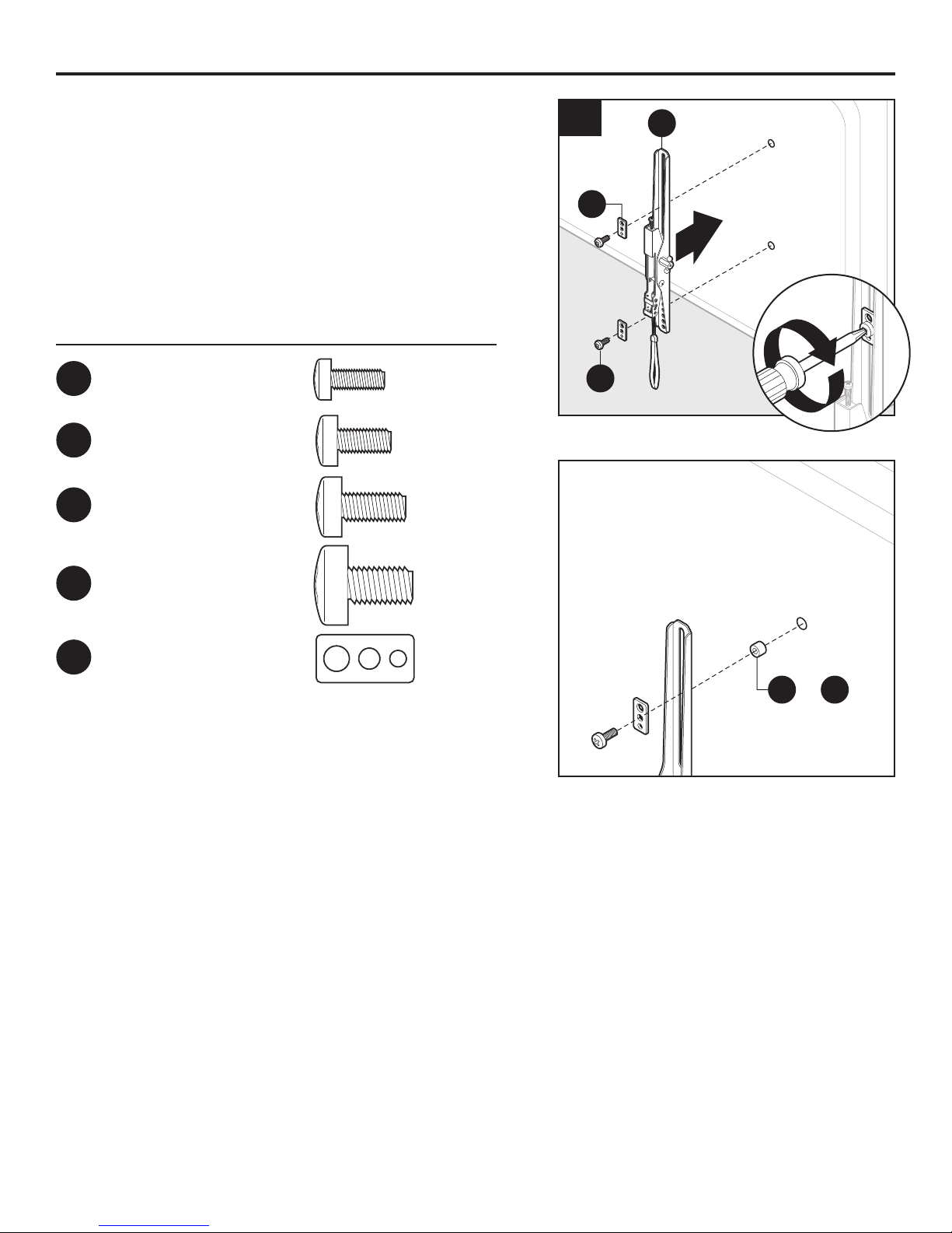
1a. Para un panel plano posterior: adhiera el riel
vertical izquierdo (C) con dos arandelas cuadradas
(KK) y dos tornillos (*). Repita el procedimiento para
el riel vertical derecho (D).
* Nota: los rieles pueden adherirse con tornillos M4 x 12
(AA), M5 x 12 (BB), M6 x 15 (CC) o M8 x 15 (DD), según
el televisor.
Aditamentos utilizados
AA
BB
CC
Tornillo M4 x 12
Tornillo M5 x 12
Tornillo M6 x 15
x 4
x 4
x 4
1a
KK
C
1
2
*
Sugerencia: se pueden utilizar
también espaciadores de 5 mm (LL)
y de 10 mm (MM) para que haya
separación entre cables y conectores.
DD
KK
Tornillo M8 x 15
Arandela cuadrada
x 4
x 4
LL or
MM
19
Page 20
INSTRUCCIONES DE ENSAMBLAJE
8 mm Lag bolt
Qty. 4
Anchor
Qty. 4
Screw
Qty. 4
M5 x 30
Screw
Qty. 4
M6 x 30
Screw
Qty. 4
M8 x 30
Screw
Qty. 4
washer
Qty. 4
KK
5 mm
Spacer
Qty. 4
LL
10 mm
Spacer
Qty. 4
MM
Steel
washer
Qty. 12
NN
washer
Qty. 4
5 mm
Spacer
Qty. 4
10 mm
Spacer
Qty. 4
Steel
washer
Qty. 12
8 mm Lag bolt
Qty. 4
Anchor
Qty. 4
Screw
Qty. 4
M6 x 30
Screw
Qty. 4
M8 x 30
Screw
Qty. 4
5 mm
Spacer
Qty. 4
LL
10 mm
Spacer
Qty. 4
MM
Steel
washer
Qty. 12
NN
8 mm Lag bolt
Qty. 4
Anchor
Qty. 4
M6 x 30
Screw
Qty. 4
M8 x 30
Screw
Qty. 4
10 mm
Spacer
Qty. 4
MM
Steel
washer
Qty. 12
NN
8 mm Lag bolt
Qty. 4
Anchor
Qty. 4
M8 x 30
Screw
Qty. 4
Steel
washer
Qty. 12
NN
5 mm
Spacer
Qty. 4
10 mm
Spacer
Qty. 4
Steel
washer
Qty. 12
10 mm
Spacer
Qty. 4
Steel
washer
Qty. 12
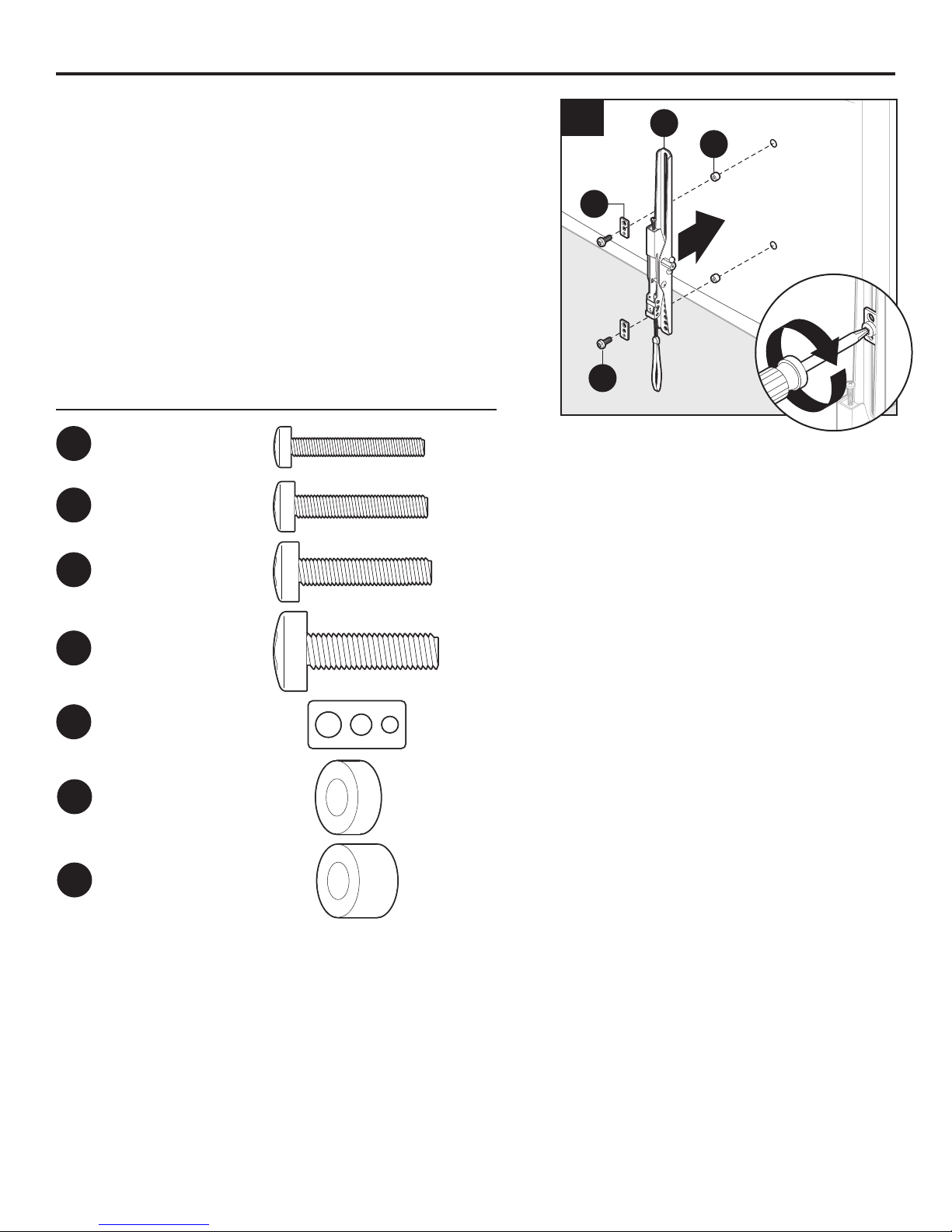
1b. Para un panel plano curvo posterior: asegure
el riel vertical (C) con cuatro espaciadores (*),
dos arandelas cuadradas (KK) y dos tornillos (**).
Repita el procedimiento para el riel vertical (D).
* Nota: el espaciador de 5 mm (LL) o el espaciador de
10 mm (MM) se pueden usar según el televisor.
** Nota: los rieles pueden adherirse con tornillos
M4 x 30 (EE), M5 x 30 (FF), M6 x 30 (GG) o M8 x 30
(HH), según el televisor.
Aditamentos utilizados
EE
FF
Tornillo M4 x 30
Tornillo M5 x 30
x 4
x 4
1b
KK
C
*
1
2
**
GG
HH
KK
Tornillo M6 x 30
Tornillo M8 x 30
Arandela cuadrada
LL
Espaciador de 5 mm
MM
Espaciador de 10 mm
x 4
x 4
x 4
x 4
x 4
20
Page 21
INSTRUCCIONES DE ENSAMBLAJE
5 mm
Spacer
Qty. 4
Phillips
screw
Qty. 8
Mounting arm screw
(preassembled to
Mounting arm (A))
Qty. 2
10 mm
Spacer
Qty. 4
Steel
washer
Qty. 8
Phillips
screw
Qty. 8
Mounting arm screw
(preassembled to
Mounting arm (A))
Qty. 2
10 mm
Spacer
Qty. 4
Steel
washer
Qty. 8
Phillips
screw
Qty. 8
Mounting arm screw
(preassembled to
Mounting arm (A))
Qty. 2
Steel
washer
Qty. 8
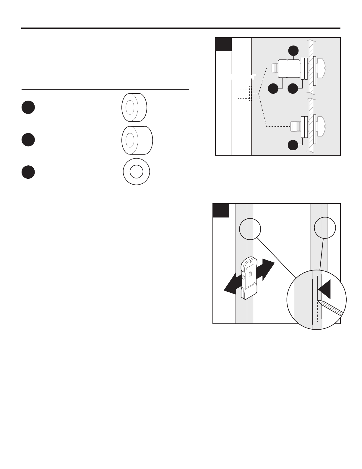
2. Si los tornillos son demasiado largos, podrían
ser necesarios más espaciadores de 5 mm (LL),
espaciadores de 10 mm (MM) y arandelas de
acero (NN).
Aditamentos utilizados
LL
MM
NN
Instalación en vigas de madera
Nota: para paredes de concreto, continúe con el
paso 7.
Espaciador de 5 mm
Espaciador de 10 mm
Arandela de acero
x 4
x 4
x 8
2
MM
TelevisorTelevisor
NNLL
NN
3
3. Utilice un detector de vigas (no se incluye)
para localizar las vigas de madera. Marque las
ubicaciones en los bordes y en el centro.
1
1
2
21
Page 22
INSTRUCCIONES DE ENSAMBLAJE
2
Qty. 4
Anchor
Qty. 4
Steel
washer
Qty. 12
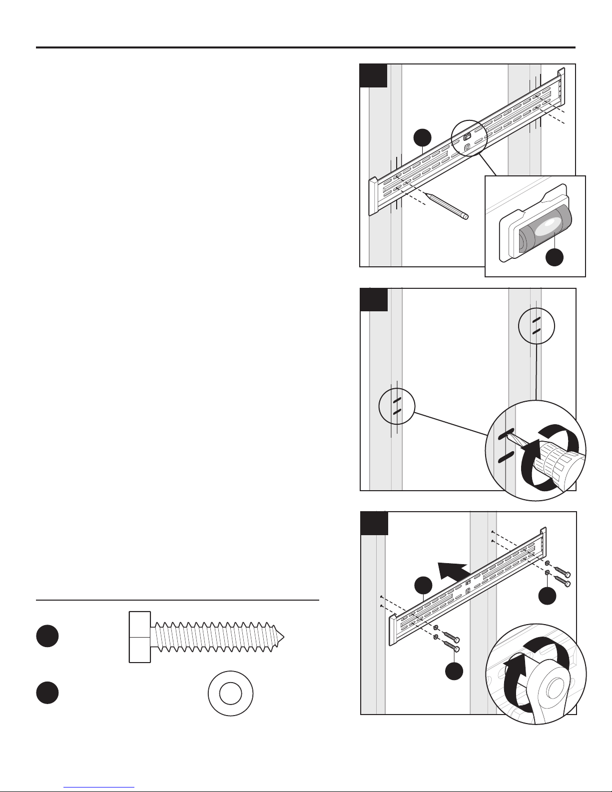
4. Utilice una placa para pared (A) para marcar las
ubicaciones de los cuatro oricios de montaje.
Nota: utilice un nivel de burbuja (B) para nivelar
la placa para pared (A).
5. Taladre cuatro oricios guía de 7/32 pulg. con
2-1/3 pulg. (60 mm) de profundidad en las
ubicaciones marcadas para los oricios de
montaje.
4
A
B
5
6. Monte la placa para pared (A) con cuatro
arandelas de acero (NN) y cuatro tirafondos de
8 mm (II) con una llave de dados de 1/2 pulg.
(no se incluye).
Aditamentos utilizados
Tirafondo
II
de 8 mm
NN
Arandela de acero
6
1
A
NN
x 4
II
x 4
22
Page 23
INSTRUCCIONES DE ENSAMBLAJE
2
Anchor
Qty. 4
Instalación en pared de concreto
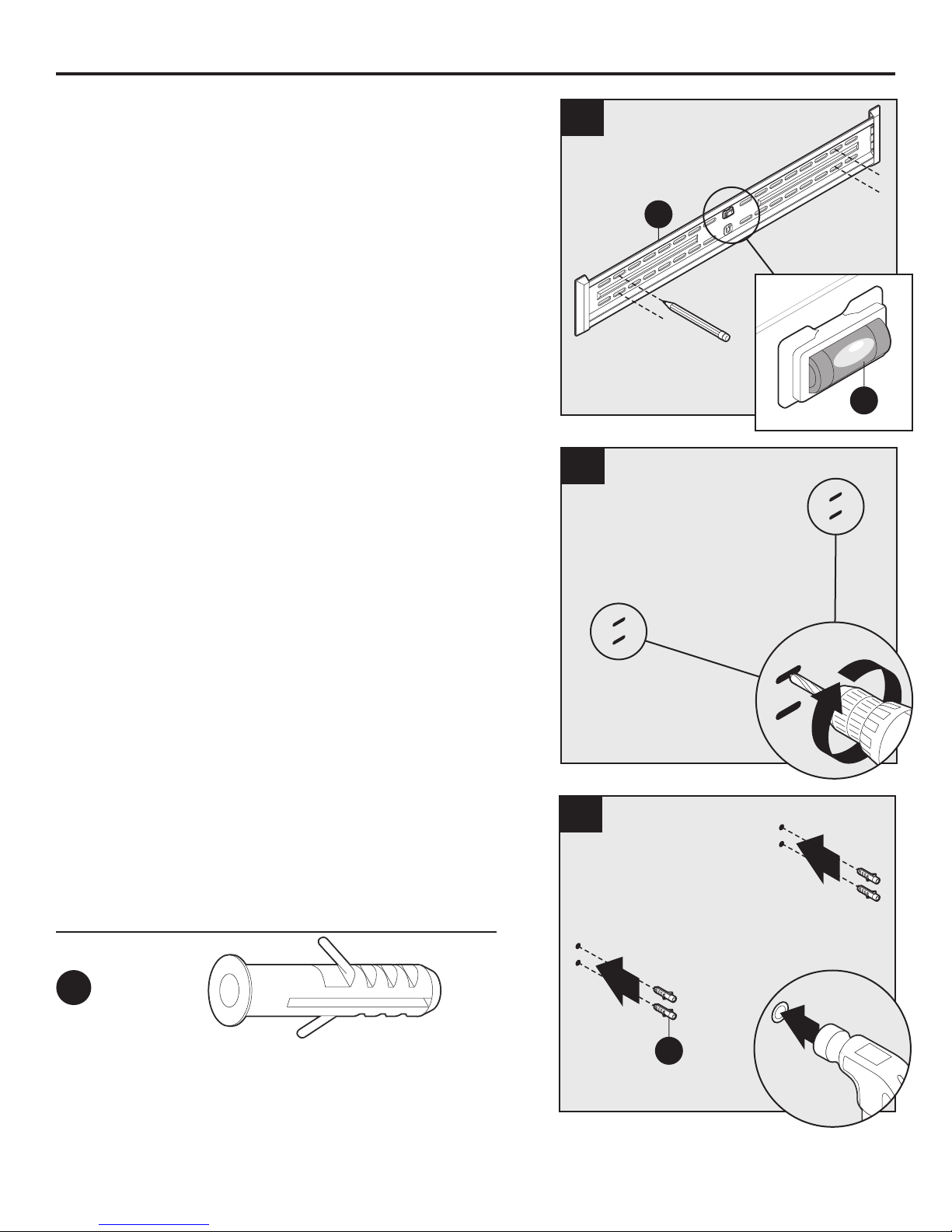
7. Utilice una placa para pared (A) para marcar las
ubicaciones de los cuatro oricios de montaje.
Nota: utilice un nivel de burbuja (B) para nivelar la
placa para pared (A).
8. Taladre cuatro oricios guía de 3/8 pulg. con
2-3/4 pulg. (70 mm) de profundidad en las
ubicaciones marcadas para las oricios de
montaje.
7
A
B
8
9. Inserte las anclas de expansión (JJ) en los
oricios. De ser necesario, golpee con un
martillo (no se incluye).
Aditamentos utilizados
JJ
Ancla de
expansión
9
1
1
x 4
JJ
23
Page 24
INSTRUCCIONES DE ENSAMBLAJE
2
Qty. 4
Anchor
Qty. 4
Steel
washer
Qty. 12
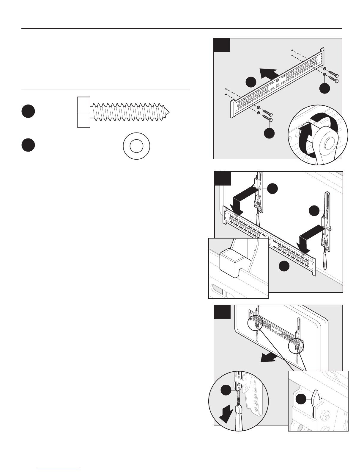
10. Monte la placa para pared (A) con cuatro
arandelas de acero (NN) y cuatro tirafondos de
8 mm (II) con una llave de dados de 1/2 pulg.
(no se incluye).
Aditamentos utilizados
Tirafondo
II
de 8 mm
NN
Instalación nal
11. Cuelgue el riel vertical derecho (C) y el
Arandela de acero
izquierdo (D) en la placa para pared (A).
10
1
A
NN
x 4
II
x 4
11
D
C
12. Jale los resortes de bloqueo (F) hacia abajo
y presione la parte inferior del panel contra la
pared. Una vez asegurado el panel, libere los
resortes de bloqueo (F).
A
12
2
F
F
1
24
Page 25
INSTRUCCIONES DE ENSAMBLAJE
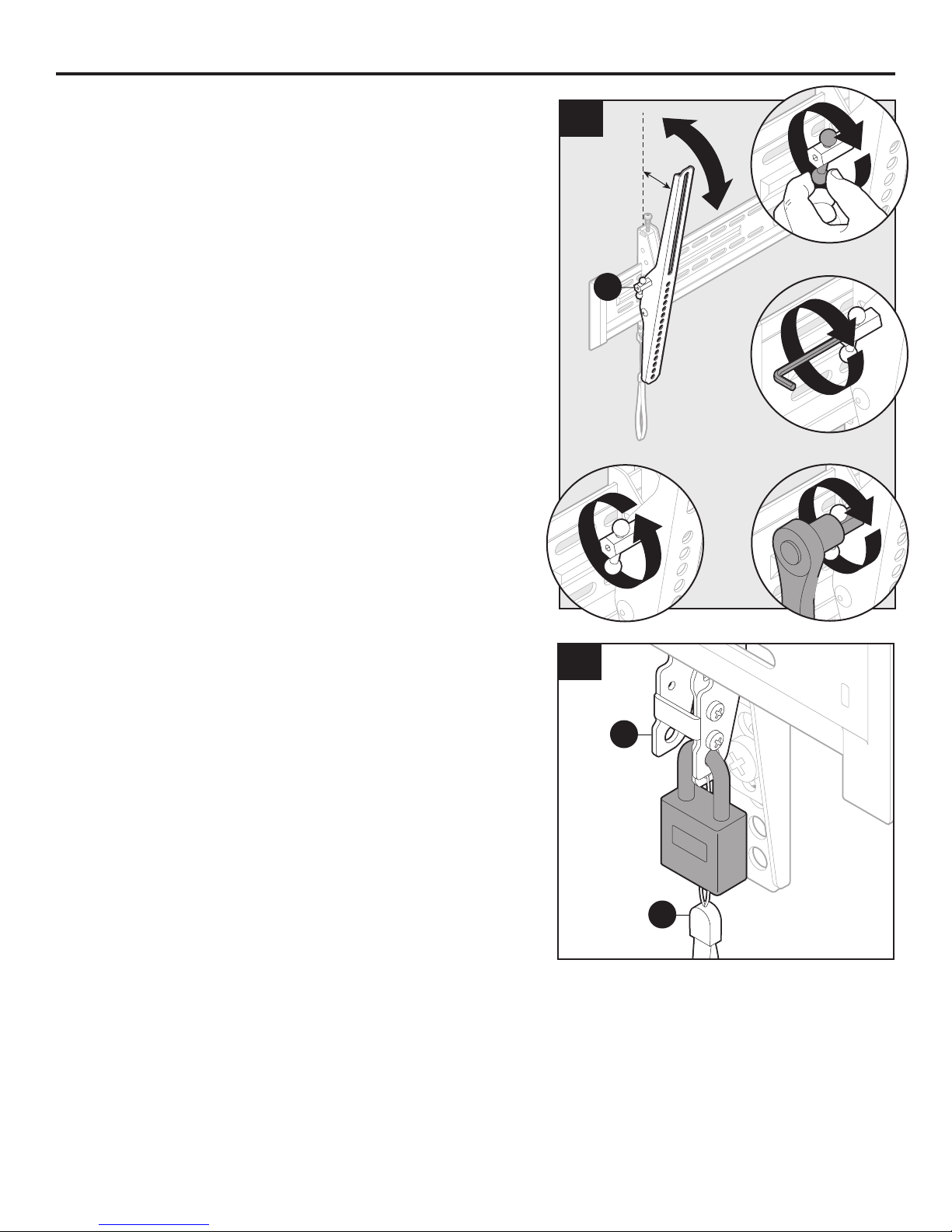
13. Para ajustar la inclinación, aoje las palancas
de inclinación (E) y mueva el panel a la
posición deseada. Apriete las palancas de
inclinación (E) para mantener la inclinación
deseada.
Nota: para obtener una explicación más clara,
vea la ilustración del panel retirado.
13
-3°–12°
E
2
2
3
o
3
5 mm
o
3
1
Seguridad adicional (opcional)
14. Asegure el panel con candados de 7 mm (no
se incluyen) para evitar robos.
1/2 pulg.
14
C/D
F
25
Page 26
INSTRUCCIONES DE ENSAMBLAJE
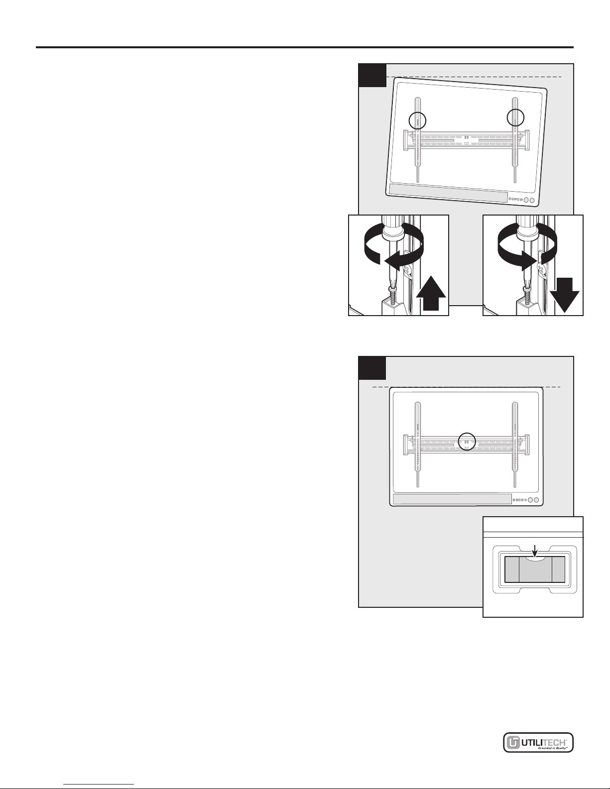
Nivelación
1. Ajuste los tornillos en los rieles verticales para
nivelar el panel plano.
1
2. Use el nivel integrado para medir el ajuste.
Nota: la burbuja en el nivel estará en el centro
cuando sea correcto.
2
Lowes.com
26
Page 27

GARANTÍA
Este producto tiene garantía contra defectos en los materiales y mano de obra por 5 años. El
fabricante reparará o reemplazará el componente o producto defectuoso según su criterio. El
incumplimiento de las instrucciones del fabricante acerca del cuidado del producto anulará la
garantía.
Para obtener el servicio de garantía, llame al Departamento de Servicio al Cliente al
1-602-674-1000. Deberá proporcionar una copia del recibo original. Si su producto debe ser enviado
para una inspección, usted se hará responsable de los cargos de envío. El producto de reemplazo
que se le envíe será devuelto con un ete prepago.
El fabricante rechaza cualquier responsabilidad por modicaciones, instalaciones inadecuadas,
instalaciones que superen el peso especicado o por incumplimiento de las instrucciones
proporcionadas. En la medida máxima permitida por la ley, el fabricante rechaza cualquier otra
garantía, expresa o implícita, incluidas aquellas garantías de idoneidad para un propósito especíco
y de comercialización.
El fabricante no se hará responsable por los daños que resulten del uso o del mal uso de este
producto.
Esta garantía le otorga derechos legales especícos, así como otros derechos que varían según el
estado.
Las especicaciones están sujetas a modicaciones sin previo aviso.
Lowes.com
27
Page 28

Impreso en China
Lowes.com
28
 Loading...