

UTICA BOILERS TriFire Assembly & Instruction Manual
KNOCKDOWN ASSEMBLY
Instructions for
TriFire Oil Fired Boiler
P/N 240007211, Rev. A [04/08]
WARNING
!
This assembly must be completed by a qualied installer or service agency, in accordance with the
manufacturer’s instructions, and in accordance with all codes and requirements of the authority having
jurisdiction. Failure to follow these instructions could result in re or explosion resulting in property dam-
age, personal injury, or loss of life.
Knockdown Boiler Assembly Instructions -
TriFire Model
Remove all components from crate. It may be to the 1.
installer’s advantage to place the cast iron boiler block
close to where the nal installation location will be.
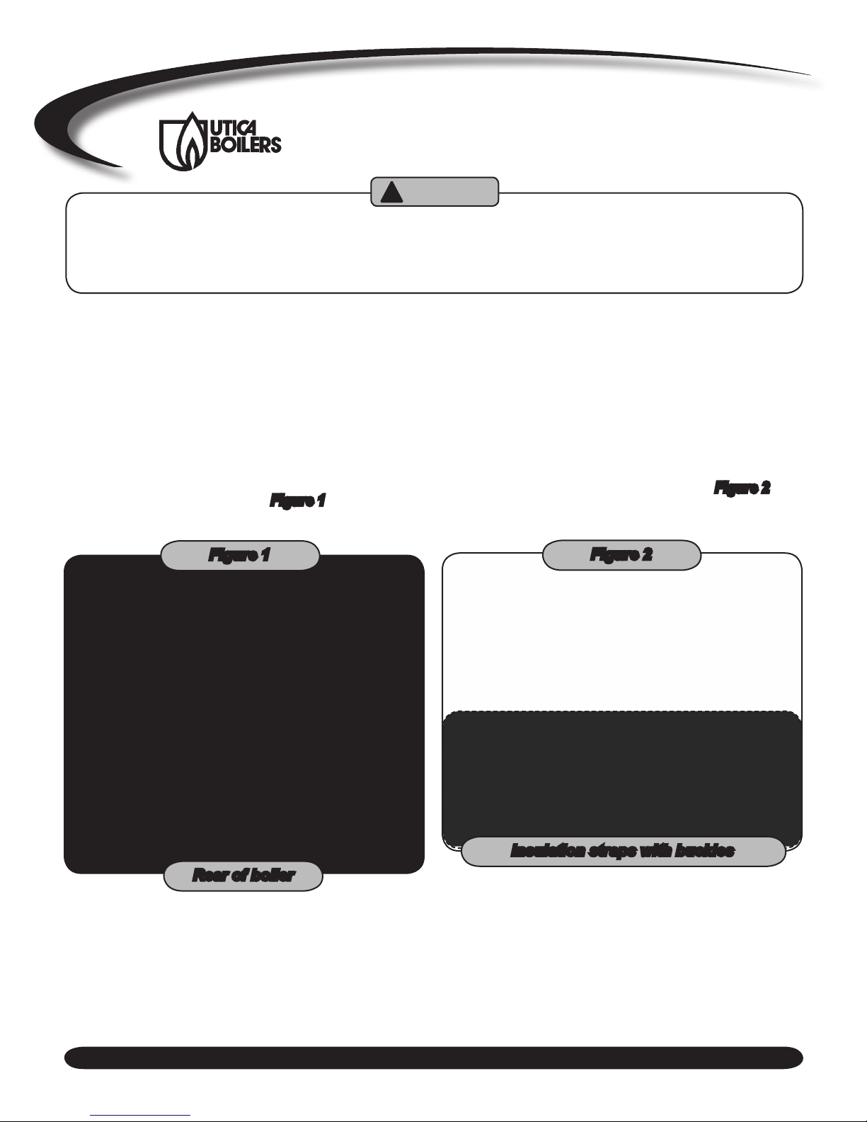
Wrap insulation around boiler with the smooth side out. 3.
Install rubber grommets in rear top plate. Attach with
2.
brass bolts and washers. See Figure 1.
If necessary, overlap underneath boiler. Wrap 2 banding strips around insulation. As shown in Figure 2,
Cinch banding together with plastic buckles provided.
Cut off excess banding material.
Figure 1
SUPPLEMENTAL INSTRUCTIONS
Rear of boiler
Figure 2
Insulation straps with buckles
1
KNOCKDOWN BOILER ASSEMBLY
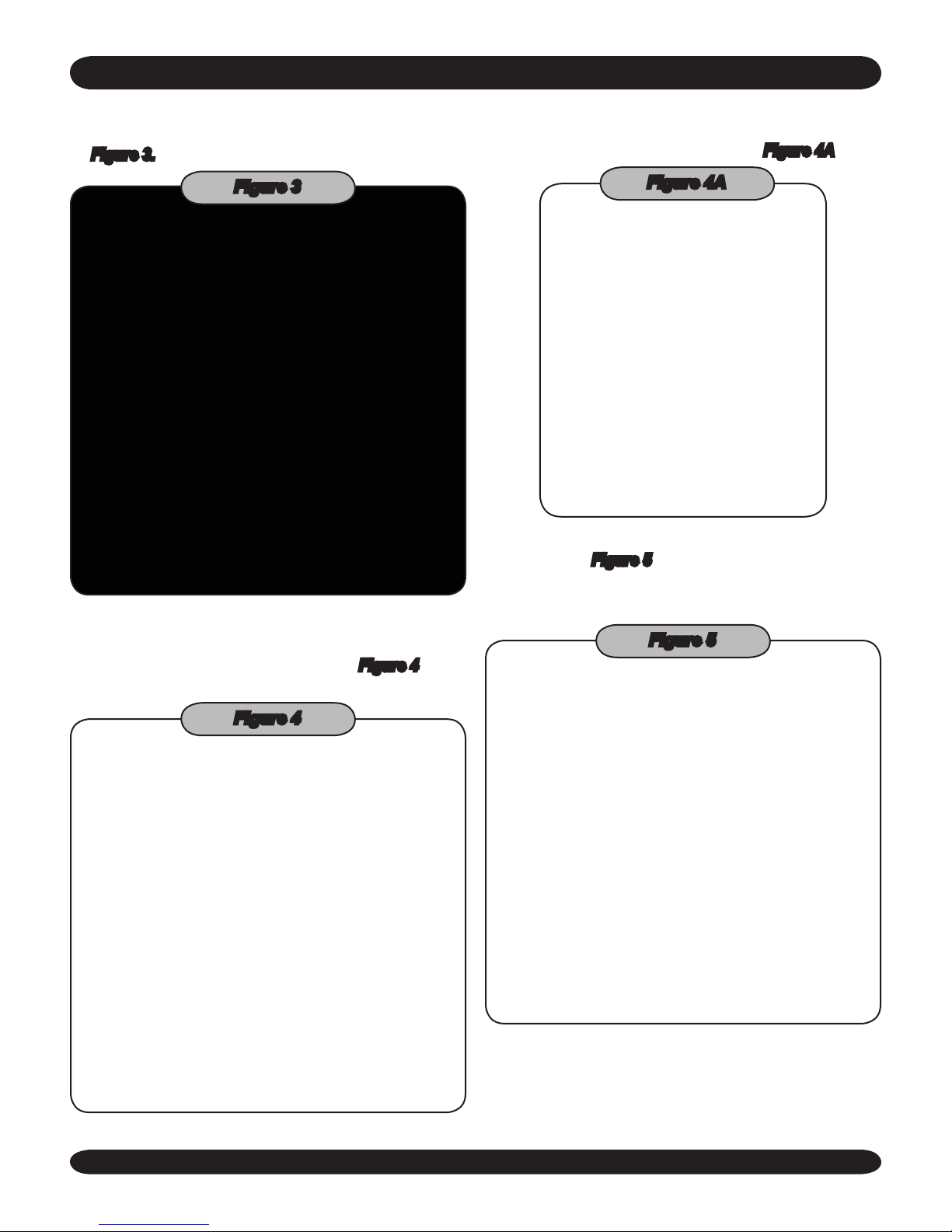
Attach pipe nipples to supply and return outlets. Be 4.
sure to use pipe dope before screwing into boiler. See
Figure 3.
Place the control panel on the top of the boiler with the 6.
burner wire harness on the right. See Figure 4A.
Figure 3
Figure 4A
Insert brass bolts into threaded holes on front of boiler 7.
as shown in Figure 5. Do not tighten down. These
bolts will hold the side Jacket panels on the boiler.
Attach insulation to rear of boiler. Attach insulation 5.
straps with plastic buckles as shown in Figure 4. Cut
off excess strap material as shown.
Figure 4
Figure 5
2
 Loading...