

Page 1
SWSW
SW
SWSW
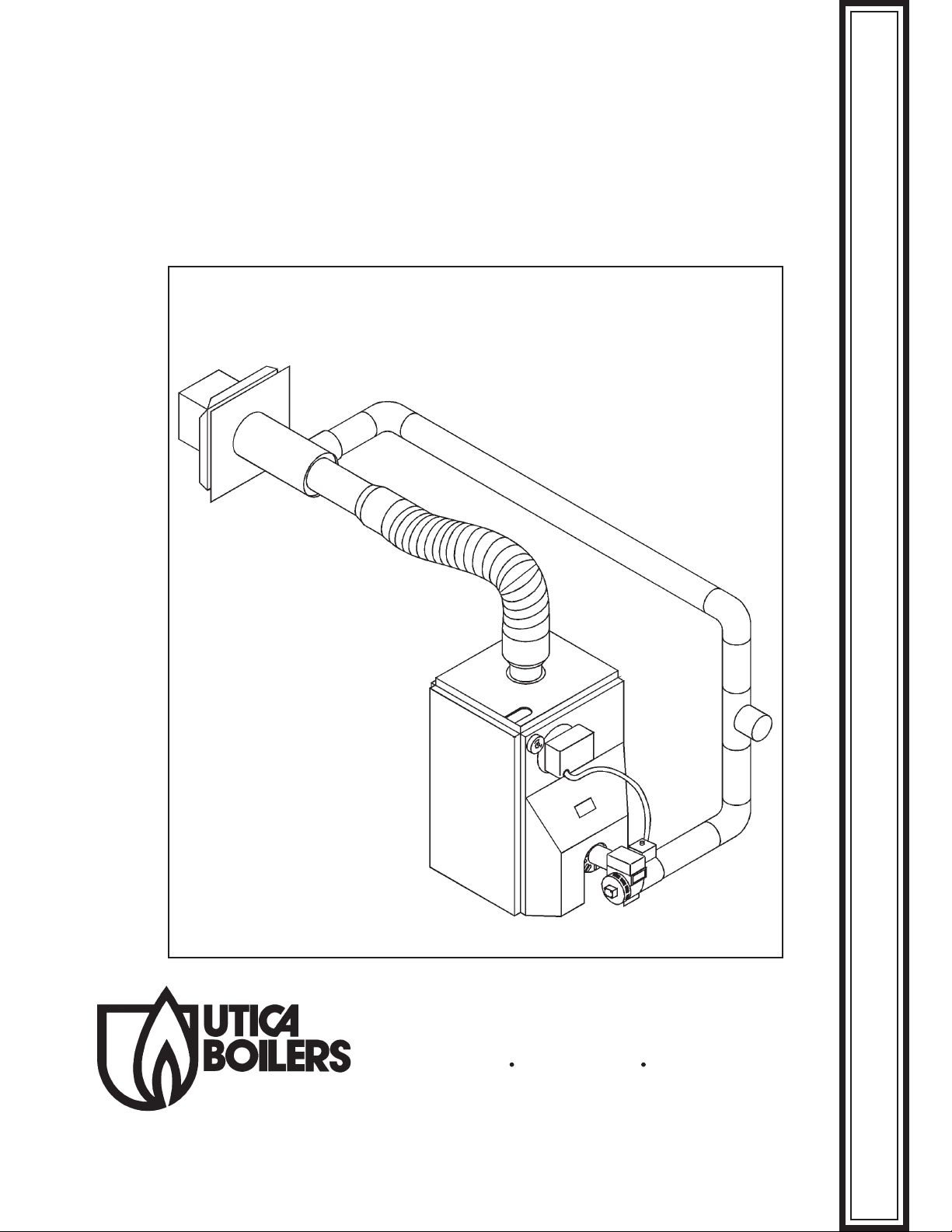
OIL FIRED DIRECT EXHAUST
CAST IRON BOILER
Utica Boilers, Inc. P.O. Box 4729 Utica, NY 13504
VENTING ADDENDUMVENTING ADDENDUM
VENTING ADDENDUMVENTING ADDENDUM
VENTING ADDENDUM
Page 2
Installation of Exhaust & Vent Piping
(Perform prior to any plumbing or electrical work)
1. Locate vent termination kit on outside of building and install in accordance with figure 3
on page 3. (make sure air inlet on termination piece is free of restriction).
2. Align the boiler with the termination kit.
3. Install vent adapters, (Note: The termination kit comes with 2 adapters, one for each
end of the vent pipe. One of the adapters has a 5/16" bolt installed.)
A. Place the adapter with the bolt on the boiler outlet.
B. Place the other adapter on the vent termination kit.
4. Measure the distance between the adapters for the vent pipe the way it would run and
add 4" to that dimension. The extra 4" is for the pipe to screw into the adapters.
5. Cut the vent pipe flush using a hacksaw having 24 teeth per inch. Dry fit the vent
adapters to the pipe and check for fit before applying RTV silicone.
6. Place a bead of RTV high temperature silicon on each vent adapter (see fig. 4) and
screw the adapters counter clockwise on to the vent pipe until seated. Tighten the 5/16"
clamps on the adapters to secure them to the vent pipes.
7. Install the adapter to the termination kit and boiler outlet and tighten the 5/16" clamps.
Place a bead of silicone around the joints where the adapter meets the boiler outlet (see
figure 5).
8. Install plumbing, electrical, oil lines and appropriate plumbing (If this step is performed
first vent installation will be difficult).
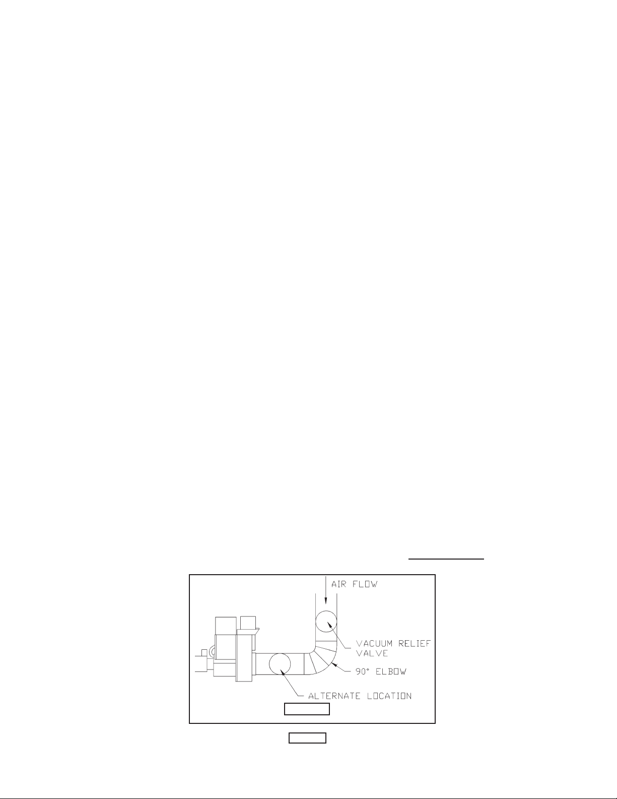
9. Install the inlet air vent and vacuum relief valve from termination to burner air inlet using
4", 26 or 30 gauge vent pipe (Do not use plastic or metal flex dryer vent as it may
collapse due to the thinness of the wall.). Secure pipe using sheet metal screws. See
fig. 1 for location of relief valve. Install vent pipe with crimps running with the air flow.
FIGURE 1
PAGE 1
Page 3
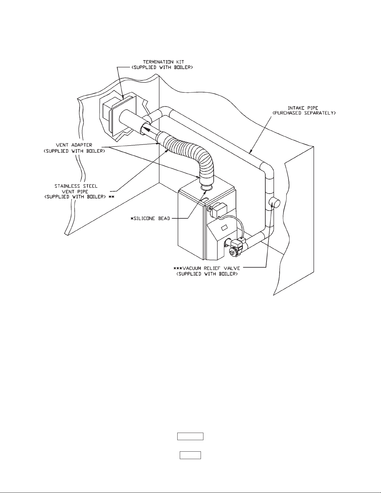
HORIZONTAL VENT PIPING TYPICAL INSTALLATION
Notes:
1 : It is recommended to install termination kit and vent pipe to boiler first
before installing supply & return piping. If not installed first, installation
of vent pipe will be difficult.
* 2 : Insert vent pipe in boiler vent outlet, apply silicone completely around
edge of outlet and tighten clamp. See figure 5 on page 4.
** 3: Maximum vent length: 10 feet.
Minimum vent length: 24 inches (2 feet).
***4: Vacuum relief valve can be installed horizontally as shown or vertically.
FIGURE 2
PAGE 2
Page 4

FIGURE 3
PAGE 3
Page 5

FIGURE 4
FIGURE 5
CACA
UTION:UTION:
CA
UTION: KEEP AREA AROUND THE VENT TERMINAL FREE OF
CACA
UTION:UTION:
SNOW, ICE, AND DEBRIS.
PAGE 4
Page 6

VENTILATION & COMBUSTION AIR
WARNING:WARNING:
WARNING: AIR OPENINGS TO COMBUSTION AREA MUST NOT BE
WARNING:WARNING:
OBSTRUCTED. BY FOLLOWING THE INSTRUCTIONS BELOW, ADEQUATE
COMBUSTION AIR CAN BE MAINTAINED
COMBUSTION AIR REQUIREMENTS
(Minimum Opening Requirements)
*UNCONFINED AREA **CONFINED AREA
Outside Inside Outside Combustion Air
Combustion Combustion VERT. DUCTS HORZ. DUCTS
BTU/HR Air 1 IN.
2
Air 1 IN.
INPUT /5000 BTU/HR /1000 BTU/HR /4000 BTU/HR /2000 BTU/HR
(Paragraph 4) (See Fig 1) (See Fig 2 & 3 (See Fig 4
(MIN. 100 IN2) Pages 5 & 6) Page 6)
91,000 19 100 23 46
140,000 28 140 35 70
2
1 IN.
2
1 IN.
2
**
* Unconfined area: A space whose volume is not less than 50 cubic feet per
**
1000 BTU per hour of all appliances installed in that space (cubic feet of space = height x
width x length).
****
** Confined area: A space whose volume is less than 50 cubic feet per 1000 BTU
****
per hour of all appliances installed in that space (cubic feet of space = height x width x
length).
1. Ventilation of the boiler room must be adequate to provide sufficient air to properly
support combustion.
2. When a boiler is located in an unconfined space in a building or conventional construction
frame, masonry or metal building, infiltration normally is adequate to provide air for
combustion and ventilation. However, if the equipment is located in a building of unusually tight
construction the boiler area should be considered as a confined space. In this case air for
combustion and ventilation shall be provided according to part 5 on page 6. If there is any
doubt, install air supply provisions in accordance with section 5.3, Air for Combustion and
Ventilation, of the latest revision of the NFPA 54 code.
3. When a boiler is installed in an unconfined space, in a building of unusually tight
construction, air for combustion and ventilation must be obtained from outdoors or from
spaces freely communicating with the outdoors. A permanent opening or openings having a
total free area of not less than 1 square inch per 5,000 BTU per hour of total input rating of
all appliances shall be provided. Ducts may be used to convey makeup air from the outdoors
PAGE 5
Page 7

and shall have the same cross-sectional area of the openings to which they are connected.
4. When air for combustion and ventilation is from inside buildings, the confined space shall
be provided with two permanent openings, one starting 12 inches from the top and one 12
inches from the bottom of the enclosed space. Each opening shall have a minimum free area
of 1 square inch per one thousand (1000) BTU per hour of the total input rating of all appliances
in the enclosed space, but must not be less than one hundred (100) square inches. These
openings must freely communicate directly with other spaces of sufficient volume so that the
combined volume of all spaces meets the criteria for an unconfined space. See figure 6 below.
5. When the boiler is installed in a confined space and all air is provided from the outdoors
FIGURE 6
FIGURE 7
the confined space shall be provided with one or two permanent openings according to
methods A or B below. When ducts are used, they shall be of the same cross sectional area
as the free area of the area of the openings to which they connect. The minimum dimension
of rectangular air ducts shall be not less than 3 x 3 inches or 9 square inches.
A. When installing two openings, one must commence within 12 inches from the top and
the other within 12 inches from the bottom of the enclosure. The openings shall communicate
directly, or by ducts, with the outdoors or spaces (crawl or attic) that freely communicate with
the outdoors. One of the following methods must be used to provide adequate air for
ventilation and combustion.
1. When directly communicating with the outdoors, each opening shall have a
minimum free area of 1 square inch per 4,000 BTU per hour of total input rating of all
equipment in the enclosure. See figure 7 above.
2. When communicating with the outdoors by means of vertical ducts, each
opening shall have a minimum free area 1 square inch per 4,000 BTU per hour of total input
rating of all appliances in the enclosed space. See figure 8 on page 7.
3. If horizontal ducts are used, each opening and duct shall have a minimum free
area 1 square inch per 2,000 BTU per hour of total input rating of all appliances in the enclosed
space. See figure 9 below.
PAGE 6
Page 8

B. One permanent opening, commencing within 12 inches of the top of the enclosure,
shall be permitted where the equipment has clearances of at least 1 inch from the sides, 1
inch from the back, and 6 inches from the front of the boiler. The opening shall directly
communicate with the outdoors or shall communicate through a vertical or horizontal duct to
the outdoors or spaces (crawl or attic) that freely communicate with the outdoors. The
openings must have a minimum free area of 1 square inch per 3000 Btu per hour of the total
input rating of all equipment located in the enclosure. The free area must be no less than the
sum of the areas of all vent connectors in the confined space.
6. In calculating free area using louvers, grilles or screens for the above, consideration
shall be given to their blocking effect. Screens used shall not be smaller than 1/4 inch mesh.
If the free area through a design of louver or grill is known, it should be used in calculating
the size opening required to provide the free area specified. If the design and free area is
not known, it may be assumed that wood louvers will have 20-25% free area and metal
louvers and grilles will have 60-75% free area. Louvers and grilles should be fixed in the open
position or interlocked with the boiler so they are opened automatically during the boiler
operation.
FIGURE 8
27515501 PAGE 7 REV: 2.1, February, 2004
FIGURE 9
 Loading...