

UTICA BOILERS SVB-2, SVB-3, SVB-6, SVB-7, SVB-4 Installation, Operation And Maintenance Manual
...
SVB SERIES II
Models
SVB-2
SVB-3
SVB-4
SVB-5
SVB-6
SVB-7
Gas-Fired Hot Water
Induced Draft Boilers
INSTALLATION, OPERATION &
MAINTENANCE MANUAL
C.S.A. Certied
For Natural Gas Or Propane
Tested For 50 psi.
ASME
Working Pressure
Manufactured by:
ECR International, Inc.
2201 Dwyer Avenue, Utica NY 13501
web site: www.ecrinternational.com
P/N 240011589, Rev. A [08/03/2016]

TABLE OF CONTENTS
Safety Messages ............................................................................................................ 3
Dimensions .................................................................................................................... 4
Boiler Ratings & Capacities .............................................................................................. 5
Installation Procedure ..................................................................................................... 6
Ventilation & Combustion Air ............................................................................................ 7
Installation System Piping ............................................................................................... 8
Vent Installation ........................................................................................................... 11
Horizontal Venting Instructions .................................................................................... 14
Optional Horizontal Venting Instruction ............................................................................ 19
Gas supply Piping ......................................................................................................... 20
Electrical Wiring ........................................................................................................... 22
Sequence of Operation .................................................................................................. 23
Wiring Diagrams ........................................................................................................... 24
Starting Your Boiler ....................................................................................................... 25
Checking and Adjusting ................................................................................................. 27
Maintaining Your Boiler .................................................................................................. 29
Service Hints ............................................................................................................... 30
Equipment & Optional Accessories .................................................................................. 31
Appendix A - Control Module ......................................................................................33
A.1 Installation Environment Considerations .............................................................. 33
A.2 Electrical Connections Connect Module Connectors ............................................... 33
A.3 Adjusting Settings ............................................................................................ 33
A.4 Display ........................................................................................................... 33
A.5 Operation ....................................................................................................... 34
A.6 Boiler High Limit Temperature Controller ............................................................. 37
A.7 Troubleshooting ............................................................................................... 37
A.8 Troubleshooting Error Codes .............................................................................. 37
A.9 Intermittent Pilot ............................................................................................. 38
2
P/N 240011589, Rev. A [08/03/2016]
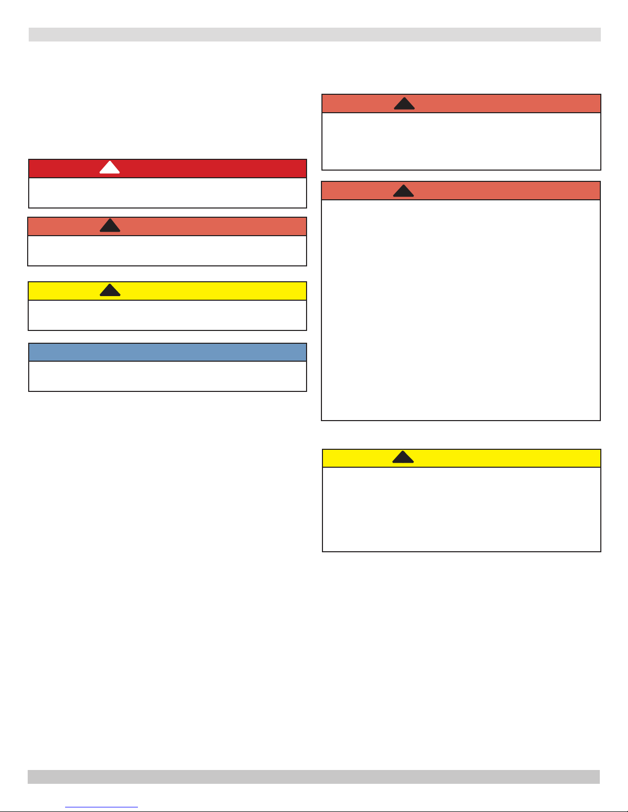
SAFETY MESSAGES
IMPORTANT: Read the following instructions
COMPLETELY before installing!!
Safety Symbols & Warnings
The following dened symbols are used throughout this
manual to notify the reader of potential hazards of varying
risk levels.
!
DANGER
Indicates a hazardous situation which, if not avoided,
WILL result in death or serious injury
!
WARNING
Indicates a hazardous situation which, if not avoided,
could result in death or serious injury.
!
CAUTION
Indicates a hazardous situation which, if not avoided,
could result in minor or moderate injury.
NOTICE
Used to address practices not related to personal
injury.
KEEP THIS MANUAL NEAR BOILER
RETAIN FOR FUTURE REFERENCE
!
WARNING
Fire, explosion, asphyxiation and electrical shock
hazard. Improper installation could result in death
or serious injury. Read this manual and understand
all requirements before beginning installation.
WARNING
!
Keep boiler area clear and free from combustible
materials, gasoline and other ammable vapors
and liquids.
DO NOT obstruct air openings to the boiler room.
Modication, substitution or elimination of factory
equipped, supplied or specied components may
result in personal injury or loss of life.
TO THE OWNER - Installation and service of this
boiler must be performed by a qualied installer.
TO THE INSTALLER - Leave all instructions with
boiler for future reference.
When this product is installed in the
Commonwealth of Massachusetts the installation
must be performed by a Licensed Plumber or
Licensed Gas Fitter.
!
CAUTION
Laceration, burn hazard. Metal edges and parts may
have sharp edges and/or may be hot. Use appropriate
personal protection equipment to include safety
glasses and gloves when installing or servicing this
boiler. Failure to follow these instructions could result
in minor or moderate injury.
3
P/N 240011589, Rev. A [08/03/2016]
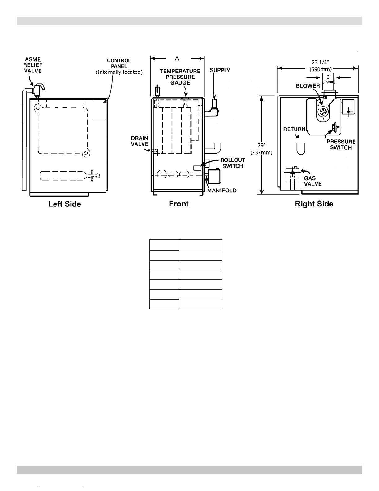
DIMENSIONS
Model Width (A)
SVB-2
SVB-3
SVB-4
SVB-5
SVB-6
SVB-7
11
14-1/4
17-1/2
20-3/4
24
27-1/4
4
P/N 240011589, Rev. A [08/03/2016]
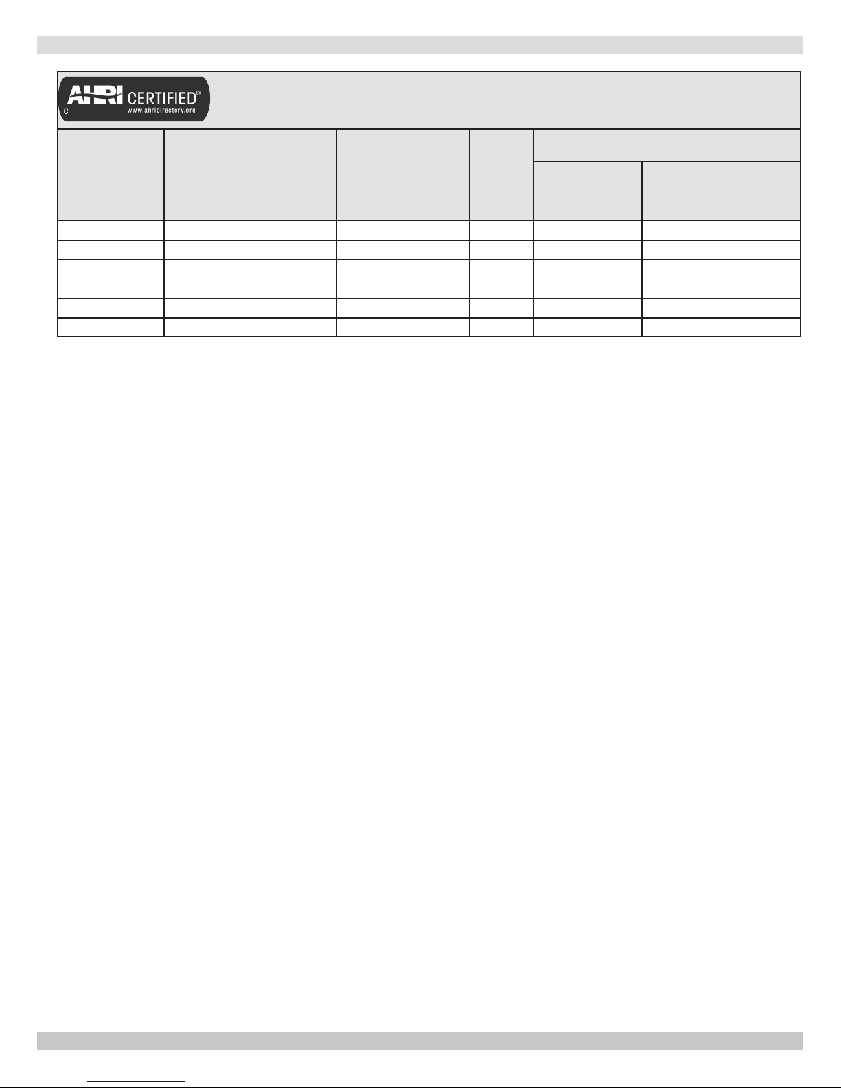
BOILER RATINGS & CAPACITIES
Table 1 - RATINGS NATURAL AND PROPANE GASES
Vent Diameter (Inches)
Model
SVB-2 42.5 36 31 84.4 4 3
SVB-3 75.0 63 55 83.4 4 3
SVB-4 112.5 94 82 83.0 4 3
SVB-5 150.0 125 109 82.7 4 3
SVB-6 187.5 155 135 82.3 4 4
SVB-7 225.0 186 162 82.0 4 4
* MBH = 1,000 Btuh = British Thermal Unit Per Hour. Boilers are equipped for altitudes up to 2,000 feet only. U.S.A.
Only - For altitudes above 2,000 feet, ratings should be reduced at the rate of 4% for each 1,000 feet above
sealevel.CanadaOnly-Boilersmaybeusedathighaltitude(2,000-4500feet/640-1350m)byusingacertied
eldconversionkit,resultingina10%de-rate.ContactProvincialauthorityhavingjurisdictionforinstallations
above 4500 ft (1350m)above sea level.+ Heating Capacity based on D.O.E. (Department of Energy) test
procedure.
**Net AHRI Water Ratings i
Input
*Mbh
Heating
Capacity
*Mbh
ndicate amount of remaining heat input that can be used to heat the radiation
or terminal units. Net AHRI Ratings shown are based on an allowance of 1.15 Selection of
boiler size should be based upon “Net AHRI Rating” being equal to or greater than calculated
heat loss of building.
Manufacturer should be consulted before selecting a boiler for installations having unusual piping
and pickup requirements.
**Net
AHRI Rating Water
*Mbh
AFUE
To Chimney
(Category I)
Horizontal Vent
(Category III)
New York City MEA Number 484-84-E Vol. IV.
This boiler cannot be used with all types of chimneys. Read these instructions carefully before installing.
These Gas-Fired Hot Water Boilers are low pressure, sectional cast iron boilers Design Certied by C.S.A. (Canadian
Standards Association) for use with Natural and Propane Gases. Constructed and hydrostatically tested for maximum
working pressure of 50 psi in accordance with A.S.M.E. Boiler and Pressure Vessel Code Section IV Standards for cast iron
heating boilers.
Boilers must stand on noncombustible oor. If installed on combustible oor, please refer to Repair Parts manual for
appropriate Combustible Floor Base part number.
Boilers For Use At High Altitude
Boiler is factory equipped for use at altitudes of 0-2,000 feet above sea level. For use at altitudes above 2,000 feet above
sea level, input ratings are reduced by change in main burner orice size.
U.S.A. Only - For altitudes above 2,000 feet above sea level, input ratings should be reduced at rate of 4% for each
1,000 feet above sea level. Consult National Fuel Gas Code (NFPA54/ANSI Z223.1), or manufacturer for correct orice
sizing information. High altitude orices are available from boiler manufacturer.
Canada Only - For altitudes in range of 2,000-4,500 feet (610 - 1350m) above sea level, boilers may be eld
equipped for use at high altitude by using a certied eld conversion kit. The change in main burner orice size results
in the boiler’s input rating being reduced by 10%.The conversion shall be carried out by a manufacturer’s authorized
representative, in accordance with the requirements of the manufacturer, provincial or territorial authorities having
jurisdiction and in accordance with the requirements of CSA-B149 Natural Gas and Propane Installation Code. The
certied eld conversion kit includes a conversion data plate, which must be attached to the boiler adjacent to the rating
plate, indicating that the boiler has been converted for high altitude use. The conversion data plate must be lled in with
the correct conversion information.
For altitudes over 4500 feet (1350m), contact Provincial authority having jurisdiction.
5
P/N 240011589, Rev. A [08/03/2016]
INSTALLATION PROCEDURE
!
WARNING
Improper installation, adjustment, alteration, service
or maintenance could result in death or serious
injury.
1.
The installation must conform to the requirements of
the authority having jurisdiction or, in the absence
of such requirements, to the National Fuel Gas Code,
ANSI Z223.1/NFPA 54, and/or Natural Gas and Propane
Installation Code, CAN/CSA B149.1
2.
Where required by authority having jurisdiction,
installation must conform to the Standard for Controls
and Safety Devices for Automatically red Boilers,
ANSI/ASME CSD-1.
3.
This boiler series is classied as a Category I. Vent
installation shall be in accordance with “Venting of
Equipment ,” of the National Fuel Gas Code, ANSI
Z223.1/NFPA 54, or “Venting Systems and Air Supply
for Appliances,” of the Natural Gas and Propane
Installation Code, CAN/CSA B149.1, or applicable
provisions of the local building codes.
4.
Boiler has met safe lighting and other performance
criteria with gas manifold and control assembly on
boiler per latest revision of ANSI Z21.13/CGA 4.9.
5.
Install such that gas ignition system components are
protected from water (dripping, spraying, rain, etc.)
during appliance operation and service, (circulator
replacement, condensate trap, control replacement,
etc.).
6.
Locate boiler on level, solid base as near chimney as
possible and centrally located with respect to heat
distribution system as practical.
7.
Verify you have the right size boiler before starting
installation. See rating and capacity table.
8.
When installed in utility room, door should be wide
enough to allow largest boiler part to enter, or to
permit replacement of another appliance such as water
heater.
9.
Boiler installed in building under construction, take
care to insure clean combustion air supply during
construction process. Airborne particulates such as
from drywall dust and from berglass insulation can
clog burner ports and cause incomplete combustion and
sooting.
!
WARNING
Fire hazard. Do not install boiler on combustible
ooring or carpeting. Failure to follow these
instructions could result in death or serious injury.
NOTICE
Follow local regulations with respect to installation
of CO detectors.
10.
FOR INSTALLATION ON NON-COMBUSTIBLE
FLOORS ONLY - For installation on combustible
ooring special base must be used. (See Replacement
Parts Section.) Do Not Install Boiler on carpeting.
11.
Verify boiler is supplied with correct type of gas, fresh
air for combustion, and suitable electrical supply.
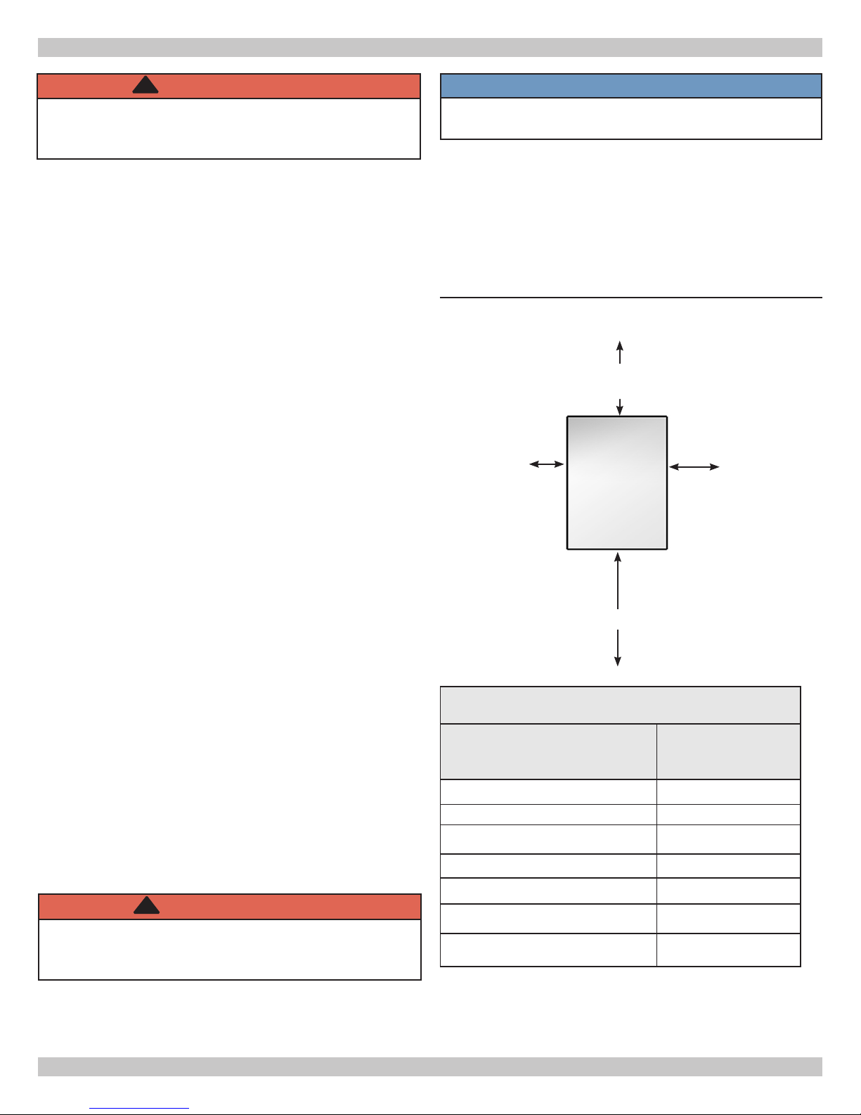
Figure 1 - Minimum Clearances To Combustible
Construction
6”
8”
Rear
Opposite Side
6”
Boiler
Front
18”
Table 2 - BOILER MINIMUM CLEARANCE TO
COMBUSTIBLES
Unit
Top 6” (152mm)
Rear 6” (152mm)
Control Side 8” (203mm)
Opposite Side 6” (152mm)
Front (Alcove) 18” (457mm)
Flue/Vent Connector 6” (152mm)
Near Boiler Piping 1” (24mm)
Control Side
8”
Minimum
Clearances
Set unit on concrete or other noncombustible material base or
oor. DO NOT INSTALL ON CARPETING.
6
P/N 240011589, Rev. A [08/03/2016]
VENTILATION & COMBUSTION AIR
Provide combustion air and ventilation air in accordance
with the section “Air for Combustion and Ventilation,” of the
National Fuel Gas Code, ANSI Z223.1/NFPA 54, or Sections
8.2, 8.3 or 8.4 of Natural Gas and Propane Installation
Code, CAN/CSA B149.1, or applicable provisions of local
building codes.
Provide make-up air where exhaust fans, clothes dryers,
and kitchen ventilation equipment interfere with proper
operation.
National Fuel Gas Code recognizes several methods
of obtaining adequate ventilation and combustion air.
Requirements of the authority having jurisdiction may
override these methods.
x Engineered Installations. Must be approved by
authority having jurisdictions.
x Mechanical Air Supply. Provide minimum of 0.35
cfm per Mbh for all appliances located within space.
Additional requirements where exhaust fans installed.
Interlock each appliance to mechanical air supply
system to prevent main burner operation when
mechanical air supply system not operating.
x All Indoor Air. Calculate minimum volume for all
appliances in space. Use a different method if
minimum volume not available.
о Standard Method. Cannot be used if known air
National Gas and Propane Installation Code Requires
providing air supply in accordance with:
inltration rate is less than 0.40 air changes per
hour. See Table 3 for space with boiler only. Use
equation for multiple appliances.
Volume ≥ 50 ft3 x Total Input [Mbh]
о Known Air Inltration Rate. See Table 3 for
space with boiler only. Use equation for multiple
appliances. Do not use an air inltration rate
(ACH) greater than 0.60.
Volume ≥ 15 ft3/ACH x Total Input [Mbh]
о Refer to National Fuel Gas Code for opening
requirements between connection indoor spaces.
x All Outdoor Air. Provide permanent opening(s)
communicating directly or by ducts with outdoors.
о Two Permanent Opening Method. Provide opening
commencing within 12 inches of top and second
opening commencing within 12 inches of bottom
enclosure.
Direct communication with outdoors or
communicating through vertical ducts. Provide
minimum free area of 1 in2 per 4 Mbh of total
input rating of all appliances in enclosure.
Communicating through horizontal ducts.
Provide minimum free area of 1 in2 per 2
Mbh of total input rating of all appliances in
enclosure.
о One Permanent Opening Method. Provide opening
commencing within 12 inches of top of enclosure.
Provide minimum clearance of 1 inch on sides
and back and 6 inches on front of boiler (does not
supersede clearance to combustible materials).
о Combination Indoor and Outdoor Air. Refer to
National Fuel Gas Code for additional requirements
for louvers, grilles, screens and air ducts.
x Combination Indoor and Outdoor Air. Refer to
National Fuel Gas Code for application information.
x Section 8.2 and 8.3 when combination of appliances
has a total input of up to and including 400 Mbh (120
kW).
о Does not have draft control device.
x Section 8.4 when combination of appliances has total
input exceeding 400 Mbh (120 kW).
x Refer to Natural Gas and Propane Installation Code
for specic air supply requirements for enclosure
or structure where boiler is installed, including air
supply openings and ducts.
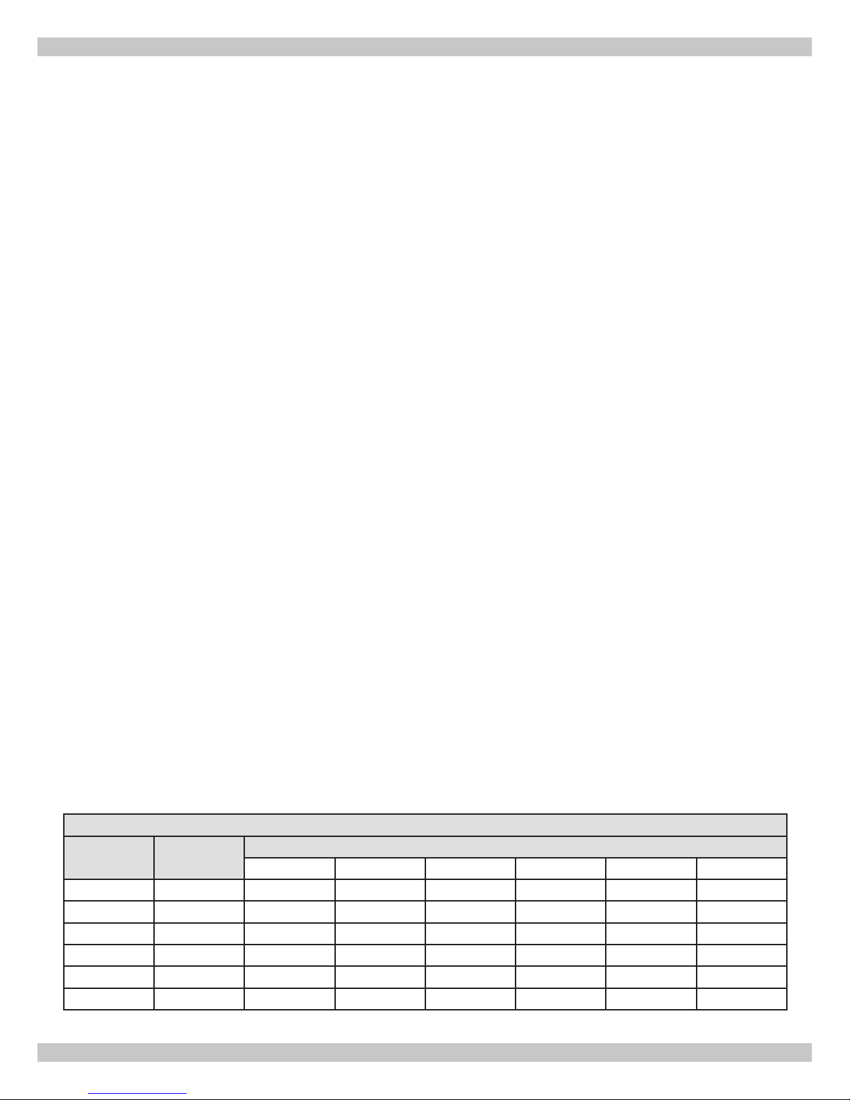
Input Mbh
Standard
Method
0.1 0.2 0.3 0.4 0.5 0.6
42.5 2125 6375 3188 2125 1594 1275 1063
75 3750 11250 5625 3750 2813 2250 1875
112.5 5625 16875 8438 5625 4219 3375 2813
150 7500 22500 11250 7500 5625 4500 3750
187.5 9375 28125 14063 9375 7031 5625 4688
225 11250 33750 16875 11250 8438 6750 5625
Table 3 - Air Inltration Rate
Known Air Inltration Rate Method (Air Changes Per Hour)
7
P/N 240011589, Rev. A [08/03/2016]
INSTALLATION SYSTEM PIPING
!
WARNING
Burn and scald hazard. Safety relief valve could
discharge steam or hot water during operation.
Install discharge piping per these instructions.
1.
Refer to local codes and appropriate ASME Boiler
and Pressure Vessel Code for additional installation
requirements. Install safety relief valve using pipe
ttings provided with boiler. See Figure 2
2.
Install safety relief valve with spindle in vertical
position.
3.
Do not install shutoff valve between boiler and safety
relief valve.
4.
Install discharge piping from safety relief valve. See
Figure 2.
x Use ¾” or larger pipe.
x Use pipe suitable for temperatures of 375°F (191°C)
or greater.
x Individual boiler discharge piping shall be independent
of other discharge piping.
x Size and arrange discharge piping to avoid reducing
safety relief valve relieving capacity below minimum
relief valve capacity stated on rating plate.
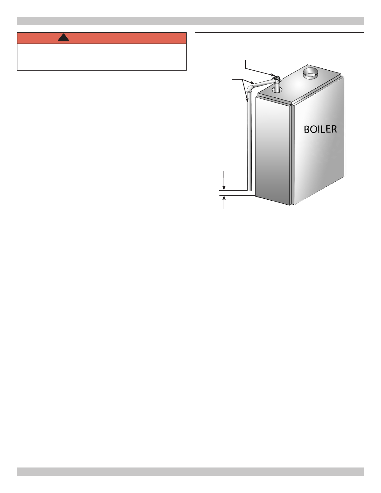
Figure 2 - Safety Relief Valve Discharge Piping
RELIEF VALVE
DISCHARGE
PIPING
Check local codes
for maximum
distance from
oor or other
allowable safe
point of discharge
x Run pipe as short and straight as possible to location
protecting user from scalding and properly drain
piping.
x Install union, if used, close to safety relief valve outlet.
x Install elbow(s), if used, close to safety relief valve
outlet and downstream of union (if used).
x Terminate pipe with plain end (not threaded).
8
P/N 240011589, Rev. A [08/03/2016]
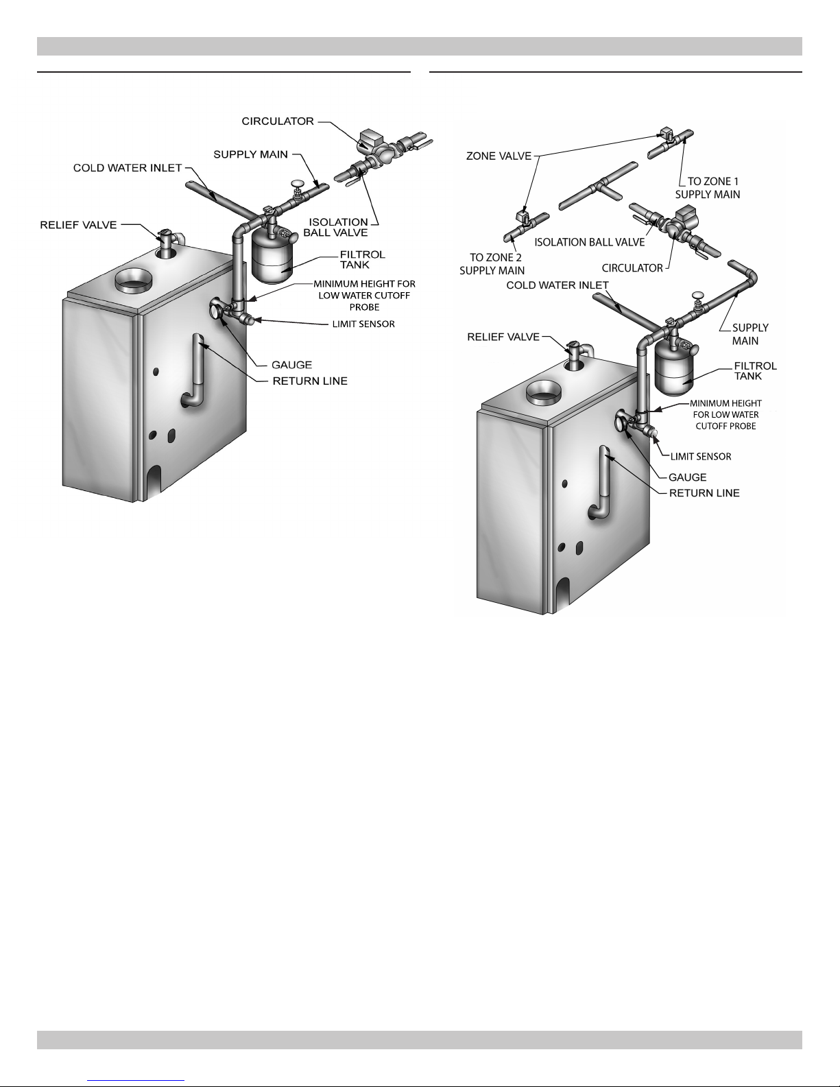
LIMIT SENSOR
MINIMUM HEIGHT FOR
LOW WATER CUTOFF
PROBE
LIMIT SENSOR
MINIMUM HEIGHT
FOR LOW WATER
CUTOFF PROBE
INSTALLATION SYSTEM PIPING
Figure 3 -
Forced Hot Water Typical Piping
Figure 4 - Forced Hot Water Typical Piping
With Zone Control Valve
9
P/N 240011589, Rev. A [08/03/2016]
INSTALLATION SYSTEM PIPING
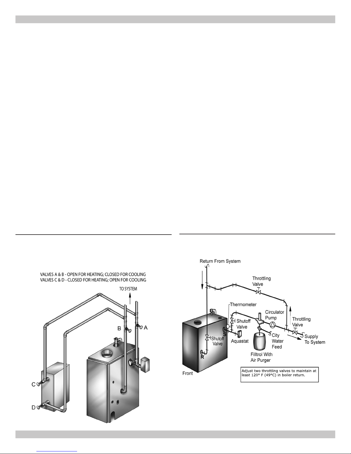
Adjust two throttling valves to maintain at
least 120° F (49°C) in boiler return.
x Install radiation units (panels, radiators or cabinets) and
supply and return mains rst then make connections at
Low Design Water Temperature Systems (Below
140°F) And Large Water Content Systems
boiler.
x Verify clean water supply is available when connecting
cold water supply to water valve. Install sand strainer at
pump when water supply is from well or pump.
Condensation is corrosive and can eventually cause severe
damage to boiler and venting system.
x Minimum design return water temperature to prevent
x Provide low water cutoff device when boiler is installed
above radiation level or as required by the Authority
having jurisdiction, either provide as part of boiler
or at time of boiler installation. Periodic inspection
x Boiler used in heating systems where design water
is necessary, as is ushing of oat type devices, per
manufacturers specic instructions. Refer to Figures 3 &
4 for minimum height for installation of LWCO. Use kit
# 550002998 and follow instructions included with kit.
When using LWCO other than kit listed follow specic
LWCO manufacturer instructions.
x Boiler connected to system having large water content
x Boiler used in connection with refrigeration systems shall
be installed so chilled medium is piped in parallel with
heating boiler with appropriate valves to prevent chilled
medium from entering heating boiler. See
Figure 5
.
x Boiler connected to heating coils located in air handling
units exposed to refrigerated air circulation, piping
system shall be equipped with ow control valves or
other automatic means to prevent gravity circulation of
boiler water during cooling cycle.
condensation in boiler and venting is 120°F. Minimum
high limit setting is 140°F.
temperatures below 140°F are desired (e.g. radiant oor
heating), a 3-way or 4-way mixing valve or suitable
alternative is required to prevent low temperature return
water from entering boiler. When using mixing valve,
follow manufacturer’s installation instructions.
(such as former gravity system), suggest use of bypass
piping. See
Figure 6
.
Figure 5
- Piping Arrangements For Boiler When
Used In Connection With Refrigeration
System
Figure 6
- Bypass Piping
10
P/N 240011589, Rev. A [08/03/2016]

VENT INSTALLATION
Check Your Chimney
Chimney must be clean, right size, properly constructed
and in GOOD CONDITION.
1.
Installation must conform to requirements of the
authority having jurisdiction or, in absence of such
requirements, to the National Fuel Gas Code, ANSI
Z223.1/NFPA 54 or of the Natural Gas and Propane
Installation Code, CAN/CSA B149.1, or applicable
provisions of the local building codes..
2.
Boiler’s induced draft blower has 3” outlet. 3” X
4” increaser tting is included in parts bag. Locate
increaser tting on outlet of induced draft blower, and
secure gas-tight with bead of furnished silicone sealant.
Increaser tting is required on this boiler for Category I
venting, and 4” is minimum permissible vent diameter.
This does not imply vent connector is intended to be 4”
diameter pipe. Vent connector shall be sized according
to appropriate venting tables in the National Fuel
Gas Code and may be required to be larger than 4”
diameter.
NOTICE
Boiler installation for chimney venting is not complete
unless increaser tting is located and secured.
3.
These are high efciency boilers with low stack or
exhaust temperature.
4.
Venting into masonry chimney without liner, line
chimney from top to bottom with either:
A. Listed Type B vent pipe
B. Listed exible vent liner
C. Poured ceramic liner.
11.
Fasten sections of vent pipe with sheet metal screws to
make piping rigid. Use stovepipe wires to support pipe
from above.
12.
Do not connect to replace ue.
13.
Do not install damper on this boiler.
Minimum Vent Pipe Clearance
x Use Type B vent pipe through crawl space. Where vent
pipe passes through combustible wall or partition, use
ventilated metal thimble. Thimble should be 4 inches
larger in diameter than vent pipe.
x Boiler installed with single wall vent, must have 6”
clearance between its surface and any combustible
material. New Type B gas vent or exible liner must be
installed in accordance with instructions furnished with
vent. Maintain clearances as specied for vent pipe.
x Verify vent pipe is re-stopped where it goes through
oor or ceiling. It should have approved vent cap with
clearances from roof. If clearances are less than shown
in have vent checked by local authorities. See Figure 7,
Page 11.
x Vent connectors serving appliances vented by natural
draft shall not be connected into any portion of
mechanical draft systems operating under positive
pressure.
5.
Outside chimneys should not be used unless they are
(choose one of the following):
A. Enclosed in a chase
B. Lined with Type B vent pipe
C. Use listed exible vent liner
D. Use certied chimney lining system
6.
Vent connector from boiler to chimney should run as
directly as possible with as few elbows as possible.
7.
Where possible, it is recommended to common vent
water heater and boiler. Consult appropriate Vent
Sizing Tables in National Fuel Gas Code for specic
requirements of multiple appliance venting.
8.
Boiler is only appliance connected to vent, Type B vent
pipe is recommended for vent connector.
9.
Slope pipe up from boiler to chimney not less than 1/4”
per foot (21mm/m).
10.
End of vent pipe must be ush with inside face of
chimney ue. Use sealed-in thimble for chimney
connection.
11
P/N 240011589, Rev. A [08/03/2016]

Liner
Chimney
Thimble
Vent System
Cleanout
Boiler
Vent pipe must be:
At lease 2 ft.
(610mm) higher
than any part of
the roof, but not
less than 3 ft.
(915mm) tall, and
within a 10 ft.
within a 10 ft.
(3m) radius of the
apex.
Boiler
Water Heater
Chimney
Figure 7 - Type B Gas Vent
VENT INSTALLATION
CHECK YOUR CHIMNEY
For boilers for connection to gas vents or
chimneys, vent installations shall be in
accordance with “Venting of Equipment”, of the
National Fuel Gas Code, ANSI Z223.1/NFPA 54,
or of the Natural Gas and Propane Installation
Code, CAN/CSA B149.1, or applicable provisions
of the local building codes.
12
P/N 240011589, Rev. A [08/03/2016]
 Loading...