

UTICA BOILERS Starfire 3 Installation Manual And Operating Instructions
STST
ST
STST
ARFIRE 3ARFIRE 3
ARFIRE 3
ARFIRE 3ARFIRE 3
WW
W
WW
OIL FIRED CAST IRON BOILER
AA
TERTER
A
TER
AA
TERTER
UCTIONSUCTIONS
UCTIONSUCTIONS
UCTIONS
TING INSTRTING INSTR
TING INSTRTING INSTR
TING INSTR
Utica Boilers • P.O. Box 4729 • Utica, NY 13504
AND OPERAAND OPERA
AND OPERAAND OPERA
AND OPERA
AL AL
AL AL
AL
TION MANUTION MANU
TION MANUTION MANU
TION MANU
ALLAALLA
ALLAALLA
ALLA
INSTINST
INSTINST
INST

TT
ABLE OF CONTENTSABLE OF CONTENTS
T
ABLE OF CONTENTS
TT
ABLE OF CONTENTSABLE OF CONTENTS
SAFETY SYMBOLS & WARNINGS ..................................................................... PAGE 1
INSTALLATION PROCEDURE ........................................................................... PAGE 2
VENTILATION AND COMBUSTION AIR ....................................................... PAGES 3-5
CONNECTING SUPPLY AND RETURN PIPING ........................................... PAGES 6-9
TANKLESS HEATER PIPING ............................................................................ PAGE 10
3/4" TAPPING OPTIONS ................................................................................... PAGE 11
VENTING SYSTEM INSPECTION & INSTALLATION ....................................... PAGE 12
OIL TANK PIPING .............................................................................................. PAGE 13
ELECTRICAL WIRING .....................................................................................PAGES 14
THERMOSTAT INSTALLATION........................................................................ PAGE 15
NORMAL SEQUENCE OF OPERATION ........................................................... PAGE 15
OPERATING INSTRUCTIONS .................................................................. PAGES 16-19
SERVICE CHECK LIST ..................................................................................... PAGE 20
REPLACEMENT PARTS LIST.....................................................................PAGES 21-28
RATINGS, DATA AND DIMENSIONS ........................................................... PAGE 29-30
KEEP THIS MANUAL NEAR BOILER. RETAIN FOR FUTURE REFERENCE
SERIES SFH 3
CAST IRON
OIL FIRED BOILER
INSTALLATION MANUAL AND OPERATING INSTRUCTIONS
PUBLISHED FEBRUARY 1996
PRINTED IN USA
MADE IN USA
TESTED FOR 100 LBS.
ASME WORKING PRESSURE
Safety SymbolsSafety Symbols
Safety Symbols
Safety SymbolsSafety Symbols
The following defined symbols are used throughout this manual to notify the
reader of potential hazards of varying risk levels.
DANGERDANGER
DANGER
DANGERDANGER
DANGER - Indicates an imminently hazardous situation which, if not avoided, WILL
result in death or serious injury.
WARNINGWARNING
WARNING
WARNINGWARNING
WARNING - Indicates a potentially hazardous situation which, if not avoided, COULD
result in death or serious injury
CAUTIONCAUTION
CAUTION
CAUTIONCAUTION
CAUTION - Indicates a potential hazardous situation which, if not avoided, MAY result
in minor or moderate injury. It may also be used to alert against unsafe practices.
IMPORIMPOR
IMPOR
IMPORIMPOR
1. Keep boiler area clear and free from combustible materials, gasoline and other
flammable vapors and liquids.
2. DO NOT obstruct air openings to the boiler room.
3. Modification, substitution or elimination of factory equipped, supplied or specified
components may result in property damage, personal injury or the loss of life.
4. To the owner: Installation and service of this boiler must be performed by a qualified
installer.
5. To the installer: Leave all instructions with the boiler for future reference.
6. When this product is installed in the Commonwealth of Massachusetts, the installation
must be performed by a licensed Plumber or Licensed Gas Fitter.
SHOULD BE DONE ONLY BY A QUALIFIED EXPERT AND INSHOULD BE DONE ONLY BY A QUALIFIED EXPERT AND IN
SHOULD BE DONE ONLY BY A QUALIFIED EXPERT AND IN
SHOULD BE DONE ONLY BY A QUALIFIED EXPERT AND INSHOULD BE DONE ONLY BY A QUALIFIED EXPERT AND IN
ACCORDANCE WITH THE APPROPRIATE UTICA BOILERS MANUAL.ACCORDANCE WITH THE APPROPRIATE UTICA BOILERS MANUAL.
ACCORDANCE WITH THE APPROPRIATE UTICA BOILERS MANUAL.
ACCORDANCE WITH THE APPROPRIATE UTICA BOILERS MANUAL.ACCORDANCE WITH THE APPROPRIATE UTICA BOILERS MANUAL.
INSTALLING OR VENTING A BOILER OR ANY OTHER GAS APPLIANCEINSTALLING OR VENTING A BOILER OR ANY OTHER GAS APPLIANCE
INSTALLING OR VENTING A BOILER OR ANY OTHER GAS APPLIANCE
INSTALLING OR VENTING A BOILER OR ANY OTHER GAS APPLIANCEINSTALLING OR VENTING A BOILER OR ANY OTHER GAS APPLIANCE
WITH IMPROPER METHODS OR MATERIALS MAY RESULT IN SERIOUSWITH IMPROPER METHODS OR MATERIALS MAY RESULT IN SERIOUS
WITH IMPROPER METHODS OR MATERIALS MAY RESULT IN SERIOUS
WITH IMPROPER METHODS OR MATERIALS MAY RESULT IN SERIOUSWITH IMPROPER METHODS OR MATERIALS MAY RESULT IN SERIOUS
INJURY OR DEATH DUE TO FIRE OR TO ASPHYXIATION FROMINJURY OR DEATH DUE TO FIRE OR TO ASPHYXIATION FROM
INJURY OR DEATH DUE TO FIRE OR TO ASPHYXIATION FROM
INJURY OR DEATH DUE TO FIRE OR TO ASPHYXIATION FROMINJURY OR DEATH DUE TO FIRE OR TO ASPHYXIATION FROM
POISONOUS GASES SUCH AS CARBON MONOXIDE WHICH ISPOISONOUS GASES SUCH AS CARBON MONOXIDE WHICH IS
POISONOUS GASES SUCH AS CARBON MONOXIDE WHICH IS
POISONOUS GASES SUCH AS CARBON MONOXIDE WHICH ISPOISONOUS GASES SUCH AS CARBON MONOXIDE WHICH IS
ODORLESS AND INVISIBLE.ODORLESS AND INVISIBLE.
ODORLESS AND INVISIBLE.
ODORLESS AND INVISIBLE.ODORLESS AND INVISIBLE.
TT
ANT!ANT!
T
ANT! READ ALL INSTRUCTIONS BEFORE INSTALLING.
TT
ANT!ANT!
WARNING:WARNING:
WARNING:
WARNING:WARNING:
WARNING:WARNING:
WARNING:
WARNING:WARNING:
ALL INSTALLATIONS OF BOILERS AND VENTINGALL INSTALLATIONS OF BOILERS AND VENTING
ALL INSTALLATIONS OF BOILERS AND VENTING
ALL INSTALLATIONS OF BOILERS AND VENTINGALL INSTALLATIONS OF BOILERS AND VENTING
PAGE 1

INSTINST
INST
INSTINST
WARNING:WARNING:
WARNING: Improper installation, adjustment, alteration, service or
WARNING:WARNING:
maintenance can cause property damage, personal injury or loss of life.
All installations must conform to the requirements of the authority having jurisdiction.
Such applicable requirements take precedence over the general instructions of this manual.
Where required by the authority having jurisdiction, the installation must conform to the
American Society of Mechanical Engineers Safety Code for Controls and Safety Devices
for Automatically Fired Boilers, ANSI/ASME No. CSD-1. In Canada all installations must
be in accordance with the authorities having jurisdiction and CSA B139.
LOCATE BOILER in front of final position before removing crate. Provide a level solid
base as near chimney as possible and centrally located with respect to the heat distribution
system as practical.
WARNING:WARNING:
WARNING: BOILER MAY NOT BE INSTALLED ON COMBUSTIBLE
WARNING:WARNING:
FLOORING.
Allow 24 inches in the front and top for servicing and cleaning, or removing tankless
water heating coil.
When installed in a utility room, the door should be wide enough to allow the largest
boiler part to enter, or to permit replacement of another appliance such as a water heater.
ALLAALLA
ALLA
ALLAALLA
TION PRTION PR
TION PR
TION PRTION PR
OCEDUREOCEDURE
OCEDURE
OCEDUREOCEDURE
FOR INSTALLATION ON NON-COMBUSTIBLE FLOORS ONLY. The boiler must not
be installed on carpeting or vinyl flooring. Minimum clearances to combustible construction
are:
TOP .............................................................. 24 IN.
FRONT ......................................................... 24 IN.
FLUE CONNECTOR ....................................... 9 IN.
REAR .............................................................. 6 IN.
SIDES ............................................................. 6 IN.
NOTE: CLEARANCE FOR ACCESS SHOULD EXCEED FIRE PROTECTION
CLEARANCE.
REMOVE CRATE and plastic protective wrapper and inspect for damage. All equipment
is carefully manufactured, inspected and packaged by experienced workers. Our responsibility
ceases upon delivery of the crated boiler to the carrier in good condition. Any claims for
damage or shortage in shipment must be filed immediately against the carrier by the
cosignee. Move boiler to permanent position by sliding or walking.
PAGE 2
VENTILAVENTILA
VENTILA
VENTILAVENTILA
WARNING:WARNING:
WARNING: AIR OPENINGS TO COMBUSTION AREA MUST NOT
WARNING:WARNING:
BE OBSTRUCTED. BY FOLLOWING THE CHART BELOW , ADEQUATE
COMBUSTION AIR CAN BE MAINTAINED.
TION & COMBTION & COMB
TION & COMB
TION & COMBTION & COMB
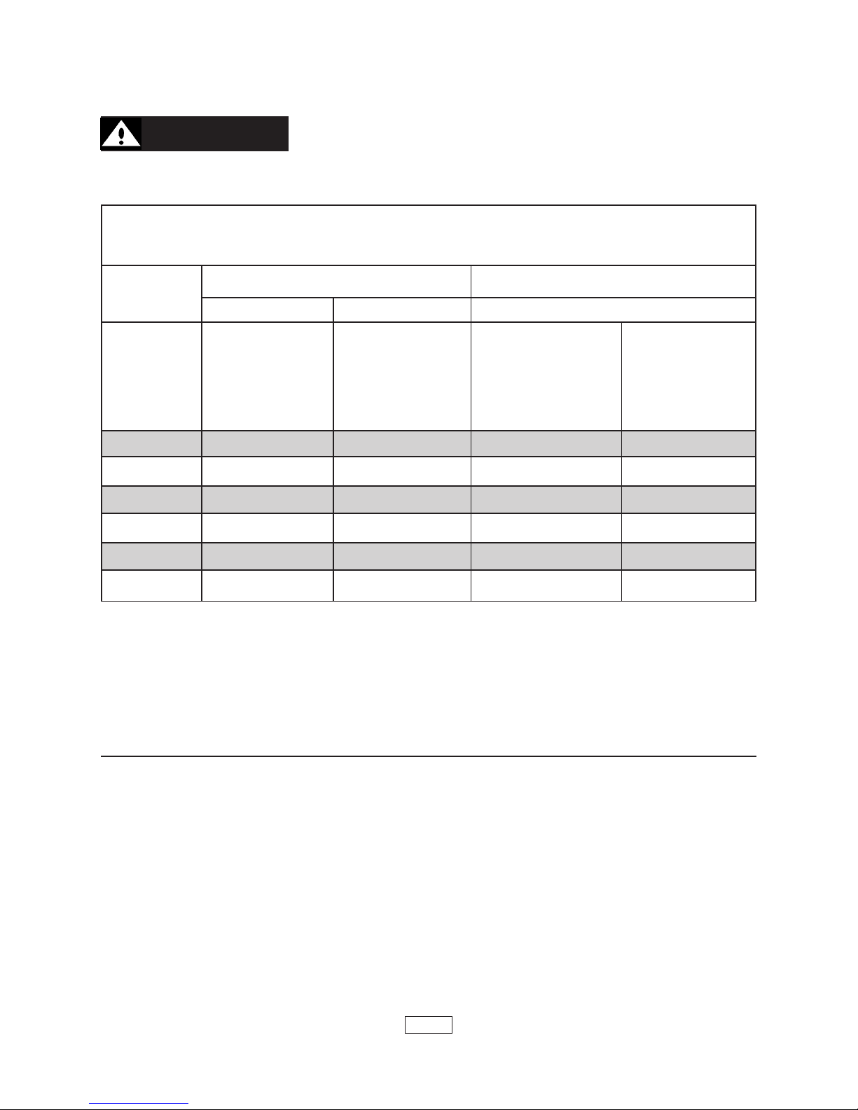
COMBUSTION AIR REQUIREMENTS
(Minimum Opening Requirements)
USTION USTION
USTION
USTION USTION
AIRAIR
AIR
AIRAIR
*UNCONFINED AREA **CONFINED AREA
Outside Inside Outside Combustion Air
Combustion Combustion VERT. DUCTS HORZ. DUCTS
BTU/HR Air 1 IN.
INPUT /5000 BTU/HR /1000 BTU/HR /4000 BTU/HR /2000 BTU/HR
(Paragraph 4) (See Fig 1) (See Fig 2 & 3 (See Fig 4
91,000 19 100 23 46
140,000 28 140 35 70
2
Air 1 IN.
(MIN. 100 IN2) Pages 5 & 6) Page 6)
2
1 IN.
2
1 IN.
2
175,000 35 175 44 88
210,000 42 210 53 106
245,000 49 245 61 122
280,000 56 280 61 140
*Unconfined area: A space whose volume is not less than 50 cubic feet per 1000
BTU per hour of all appliances installed in that space (cubic feet of space = height x
width x length).
**Confined area: A space whose volume is less than 50 cubic feet per 1000 BTU
per hour of all appliances installed in that space (cubic feet of space = height x width x
length).
1. Ventilation of boiler room must be adequate enough to provide sufficient air to
properly support combustion.
2. When a boiler is located in an unconfined space in a building of conventional
construction frame, masonry or metal, infiltration normally is adequate to provide air for
combustion and ventilation. However, in any building which has been altered to conserve
energy or to minimize infiltration, the boiler area should be considered as a CONFINED
SPACE. If there is any doubt, install air supply provisions for combustion and ventilation in
accordance with section 5.3, Air for Combustion and Ventilation, of the NFPA 54 1988 code,
the recommendations that follow, or applicable provisions of the local building codes.
3. When a boiler is installed in an unconfined space, in a building of unusually tight
construction, air for combustion and room ventilation must be obtained from outdoors or
from spaces freely communicating with the outdoors. A permanent opening or openings
PAGE 3
having a total free area of not less than 1 square inch per 5,000 BTU per hour of total input
rating of all appliances shall be provided. Ducts may be used to convey make-up air from
the outdoors and shall have the same cross-sectional area of the openings to which they
are connected.
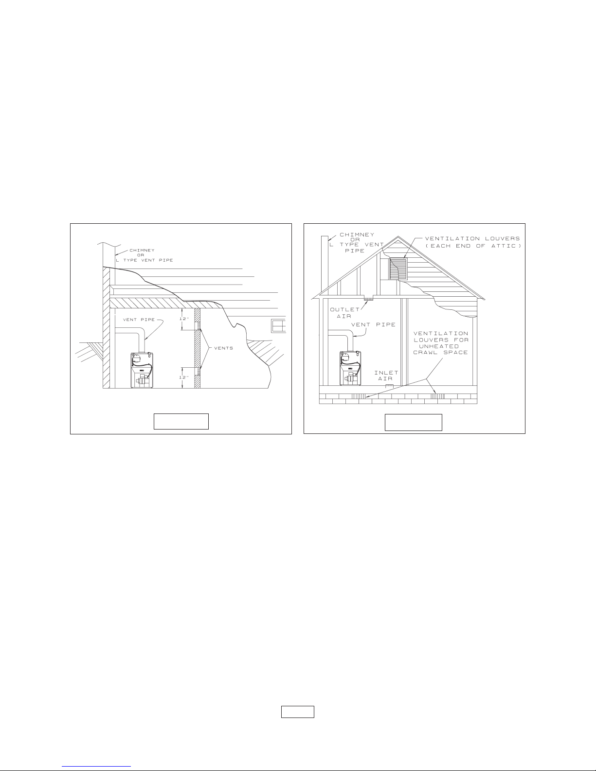
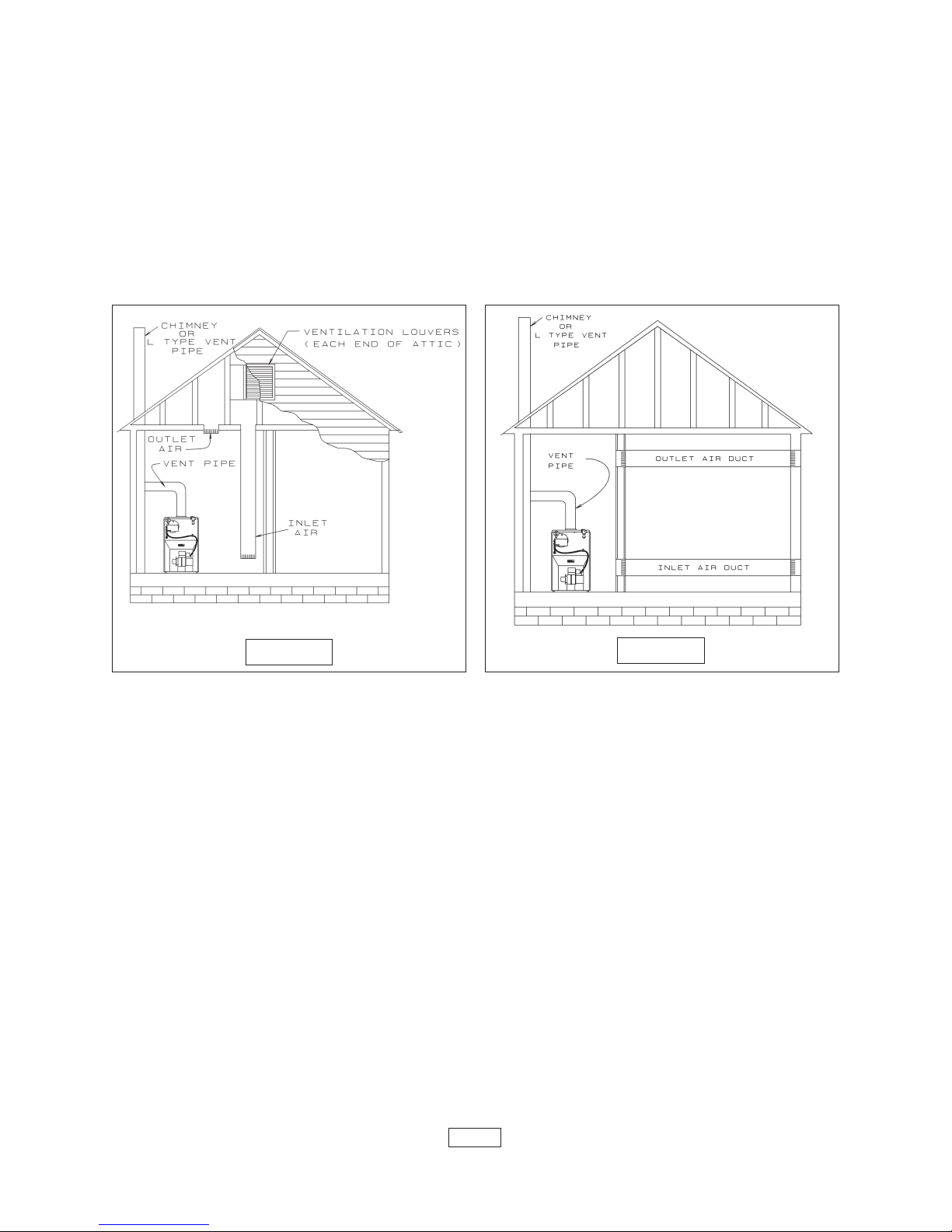
4. When air for combustion and room ventilation is from inside buildings, the confined
space shall be provided with two permanent openings, one starting 12 inches from the top
and one 12 inches from the bottom of the enclosed space. Each opening shall have a
minimum free area of 1 square inch per one thousand (1,000) BTU per hour of the total input
rating of all appliances in the enclosed space, but must not be less than one hundred (100)
square inches. These openings must freely communicate with the interior areas having
adequate infiltration from the outside. See figure 1 below.
FIGURE 1
FIGURE 2
5. When the boiler is installed in a confined space and all air is provided from the outdoors,
the confined space shall be provided with two permanent openings, one commencing within
12 inches from the top and one commencing 12 inches from the bottom of the enclosure. The
openings shall communicate directly, or by ducts, with the outdoors or spaces (crawl or attic)
that freely communicate with the outdoors. One of the following methods must be used to
provide adequate air for ventilation and combustion.
A. When directly communicating with the outdoors, each opening shall have a minimum
free area of 1 square inch per 4,000 BTU per hour of total input rating of all equipment in
the enclosure. See figure 2, above.
B. When communicating with the outdoors by means of vertical ducts, each opening
shall have a minimum free area 1 square inch per 4,000 BTU per hour of total input rating
of all appliances in the enclosed space. See figure 3 on page 5.
C. If horizontal ducts are used, each opening shall have a minimum free area 1 square
inch per 2,000 BTU per hour total input rating of all appliances in the enclosed space. See
figure 4, on page 5.
D. When ducts are used, they shall be of the same cross sectional area as the free area
of the area of the openings to which they connect. The minimum dimension of rectangular
PAGE 4
air ducts shall not be less than 3 inches.
6. In calculating free area using louvers, grills or screens for the above, consideration
shall be given to their blocking effect. Screens used shall not be smaller than 1/4 inch mesh.
If the free area through a design of louver or grill is known, it should be used in calculating
the size opening required to provide the free area specified. If the design and free area is
not known, it may be assumed that wood louvers will have 20-25% free area and metal
louvers and grills will have 60-75% free area. Louvers and grills shall be fixed in the open
position or interlocked with the boiler so that they are opened automatically during boiler
operation. See chart on page 4 for combustion air minimum opening requirements.
FIGURE 3
FIGURE 4
PAGE 5
CONNECTING SUPPLCONNECTING SUPPL
CONNECTING SUPPL
CONNECTING SUPPLCONNECTING SUPPL
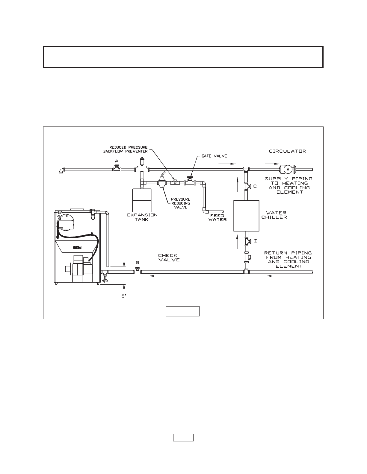
IMPORTANT: Circulators in the following illustrations are mounted on the system supply
side, but mounting on the system return side is also acceptable practice.
1. Connect supply and return piping as suggested in figure 5, below. When the boiler is
used in connection with refrigerated systems:
A. The chilled medium MUST BE IN PARALLEL with the boiler.
B. Use appropriate valves to prevent the chilled medium from entering the heating boiler.
Y Y
AND RETURN PIPINGAND RETURN PIPING
Y
AND RETURN PIPING
Y Y
AND RETURN PIPINGAND RETURN PIPING
2. During the heating cycle open valves A and B, close valves C and D.
3. During heating cooling cycle open valves C and D, close valves A and B.
A. Maintain a minimum clearance of one inch to hot water pipes.
In air handling units where they may be exposed to refrigerated air circulation, the
boiler piping system MUST be supplied with flow control valves or other automatic means
to prevent gravity circulation of the boiler water during the cooling cycle.
4. Hot water boilers installed above radiation level must be provided with a low water
device either as part of the boiler or at the time of boiler installation.
5. When a boiler is connected to a heating system that utilizes multiple zoned circulators,
each circulator must be supplied with a flow control valve to prevent gravity circulation.
FIGURE 5
PAGE 6
* Reduced pressure back flow preventer must be used under provisions required by the
Environmental Protection Agency, (EPA).
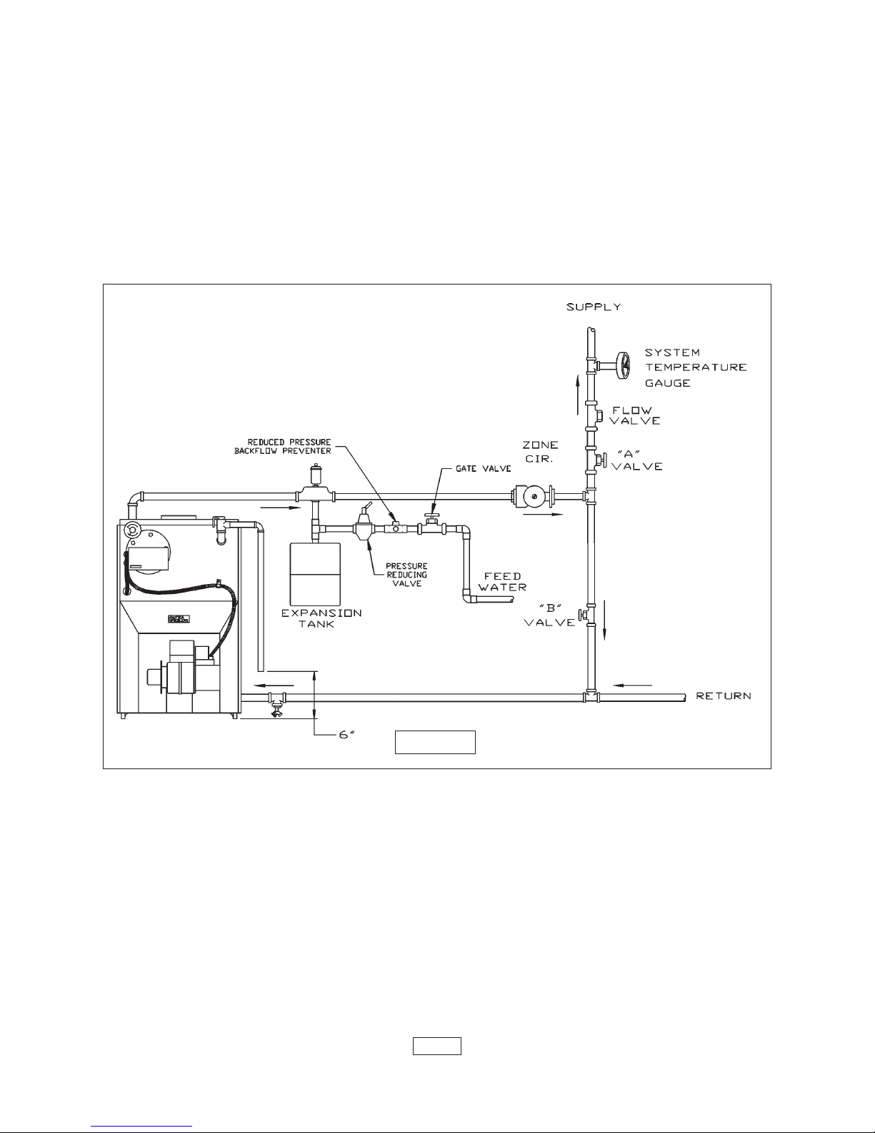
6. Bypass piping is an option which gives the ability to adjust the supply boiler water
temperature to fit the system or condition of the installation. Although, this method of
piping is not typically required for baseboard heating systems.
A. This method is used to protect boilers from condensate forming due to low temperature
return water. Generally noticed in large converted gravity systems or other large water volume
systems. See figure 6 below.
BYPASS PIPING
B. These methods are used to protect systems using radiant panels and the material
they are encased in from high temperature supply water from the boiler and protect the boiler
from condensation. See figures 7 and 8 on page 8.
C. This method is used to protect boilers from condensate forming as well as
protecting the heating system from high water temperature. See figure 8 on page 8.
7. Note: When using bypass piping, adjust valves A and B until desired system
temperature is obtained.
8. Bypass loop piping must be the same size piping for the supply and return.
FIGURE 6
PAGE 7
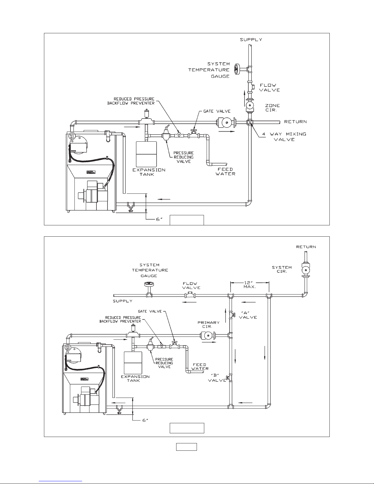
MIXING-VALVE PIPING
FIGURE 7
PRIMARY SECONDARY PIPING WITH BYPASS
FIGURE 8
PAGE 8
 Loading...