

Page 1
Instruction Manual
in.-lb. Nm in.-lb. Nm
TCI-150RA * 30-150 3.4-17.0 1.0 0 . 1 1 1/4"
TCI-150RA-3/8 * 30-150 3.4-17.0 1.0 0 . 1 1 3/8"
TCI-250R * 50-250 5.7-28.3 1.0 0 . 1 1 3/8"
TCI-750R 150-750 ------ 5.0 ------ 3/8"
TCI-750R-1/2 150-750 ------ 5.0 ------ 1/2"
* Note: Dual Scale Model
ft.-lb. Nm ft.-lb. Nm
TCI-75FRN * 15-75 20.3-102 0.5 0.7 3/8"
* Note: Dual Scale Model
in.-lb. Nm in.-lb. Nm
CH-150 * 30-150 3.4-17.0 1.0 0 . 1 1 --* Note: Dual Scale Model
ft.-lb. Nm ft.-lb. Nm
CH-75F *
15-75 20.3-102 0.5 0.7 --CH-150F * 30-150 40.7-203 1.0 1.4 --* Note: Dual Scale Model
in.-lb. Nm ft.-lb. cm-kg
CHA-6 10-50 1.2-6 0.9-4.5 12-60 --CHA-11 20-100 2.2-11 1.6-8 22-110 --CHA-23 40-200 4.6-23 3.4-17 46-230 --CHB-55 100-500 11-55 8-40 112-560 --CHB-85 150-750 17-85 12.5-62.5 172-860 --CHB-110 200-1000 22-110 16-80 224-1120 --CHB-170 300-1500 34-170 25-125 346-1730 --CHB-225 400-2000 45-225 33-165 460-2300 ---
Torque Range
Graduations
Drive Size
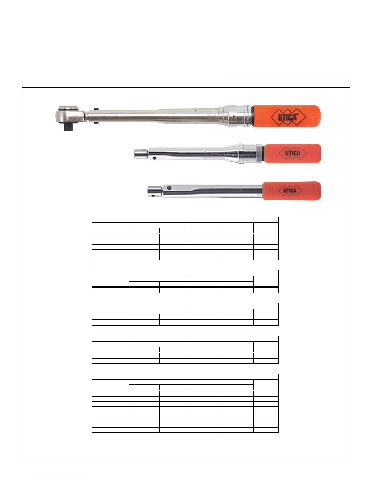
Single Setting (Preset) Wrench
Model No.
Drive Size
Torque Range
Model No.
Model No.
Torque Range
Graduations
Drive Size
Micrometer Adjustable Wrench (in.-lb. Graduations)
Model No.
Torque Range
Graduations
Drive Size
Micrometer Adjustable Wrench (ft.-lb. Graduations)
Model No.
Ratchet Head (in.-lb. Graduations)
Drive Size
Torque Range
Graduations
Ratchet Head (ft.-lb. Graduations)
45-8448
®
Utica
CH & TCI Series
Click Type Torque Sensing Wrenches
Ratchet Head
Micrometer Adjustable
Single Setting
Note: Single setting wrenches do not have a scale and must be set on a torque tester.
Page 2

45-8448
Utica
®
“Click” Type Torque Sensing Wrenches
Micrometer Adjustable Torque Sensing Wrenches:
These torque sensing wrenches automatically signal by
SOUND and IMPULSE when the desired torque is reached.
These wrenches are calibrated for right hand (clockwise) and
left hand (counter clockwise) torque applications.
Setting a Torque:
Unlock: Pull back, fully, and hold the automatic lock collar.
While holding the lock collar, advance the handle up the barrel
by turning it in a clockwise direction or counter clockwise to
move down the barrel. The barrel is marked in even increments
of torque and one complete turn of the handle will change the
torque setting one complete barrel increment.
If the barrel is marked in increments of ten, each complete
turn of the handle would change the torque setting by ten.
The sleeve die is marked around the circumference with
intermediate increments.
The sleeve die markings start at 10 and are divided into ten
equal marks. Every other mark is numbered. To set at an even
barrel increment the zero marking on the sleeve die should line
up with the center of the barrel marking, see Figure 1.
Figure 1
Center
Line Barrrel
Marking
Barrel Die
Increment
Sleeve Die
Increment
By advancing the handle one sleeve die mark you have
increased the torque an amount equal to 1/10th the increase
between two barrel increments, see Figure 2.
Figure 2
Lock:
When you have lined up a sleeve die mark with the center
line barrel mark, you can release the lock collar and it will
automatically move forward and lock the handle to the barrel.
To Use:
Attach the appropriate socket wrench or adapter to the torque
wrench square drive and apply to the application. Hold the
torque wrench by the padded handle and tighten the fastener.
Apply force with a steady, smooth action.
Do not apply force by holding any part of the wrench, other
than the padded handle. Do not use an extension or other
lever aid on the handle. When the torque setting is reached,
the wrench will momentarily release with a feel impulse and
audible click. The wrench will move freely through a small arc
of approximately two (2) degrees. At this point the set torque
has been achieved and force on the handle must be released.
The wrench will automatically snap back to it’s original position
and is ready for the next torque application.
NOTE: When set at the lower torque range, the audible signal
will be much lower. However, there is an audible sound which
in conjunction with the feel impulse should present no difculty
in operating the wrench at the lower scale settings.
Torque Extensions:
When an extension is used on the drive end of the torque
wrench, the torque applied at the end of the extension is NOT
the same as the torque setting on the wrench. The method of
determining the actual torque produced using various types of
extensions is as follows:
Ta = Torque applied at the end of extension
Tw = Torque Wrench setting
L = Length of wrench (center of handle to drive)
A = Length of extension *
* Note: Dimension always taken parallel to the line of
the wrench regardless of extension conguration.
If the barrel increments are 10, 20, etc. and the original setting
was 30, by moving the handle on the sleeve die one increment
you increase the torque an amount equal to 1. Your new torque
setting would be 31. If you turned the handle four (4) sleeve die
marks in a clockwise direction from zero you have advanced
the torque four (4) increments and your new torque setting
would be 34, see Figure 3.
Figure 3
Figure 4
NOTE: To obtain the actual torque values as calculated, force
must be applied only at the center point of the handle.
Page 3
Utica
®
“Click” Type Torque Sensing Wrenches
45-8448
Torque Settings for Dual Scale Models
TCI-150RA, TCI-150RA-3/8, TCI-250R, TCI-75FRN, CH-150,
CH-75F and CH-150F:
The torque settings of these wrenches are read from two
micrometer scales: Major and Fine. These wrenches can be
utilized in Foot-Pounds (ft-lbs) or Inch-Pounds (in-lbs) and
Newton meters (Nm) applications. Therefore there are two
major and ne scales. The ft-lb or in-lb and Nm scales are on
opposite sides of the barrel.
Scale increments:
TCI-75FRN and CH-75F:
Major ft-lb = 5 ft-lbs
Fine ft-lb = 0.5 ft-lbs
Major Nm = 6.8 Nm
Fine Nm = 0.7 Nm (rounded)
TCI-150RA, TCI-150RA-3/8, TCI-250RA and CH-150:
Major in-lb = 10 in-lbs
Fine in-lb = 1 in-lbs
Major Nm = 1.1 Nm
Fine Nm = 0.11 Nm (rounded)
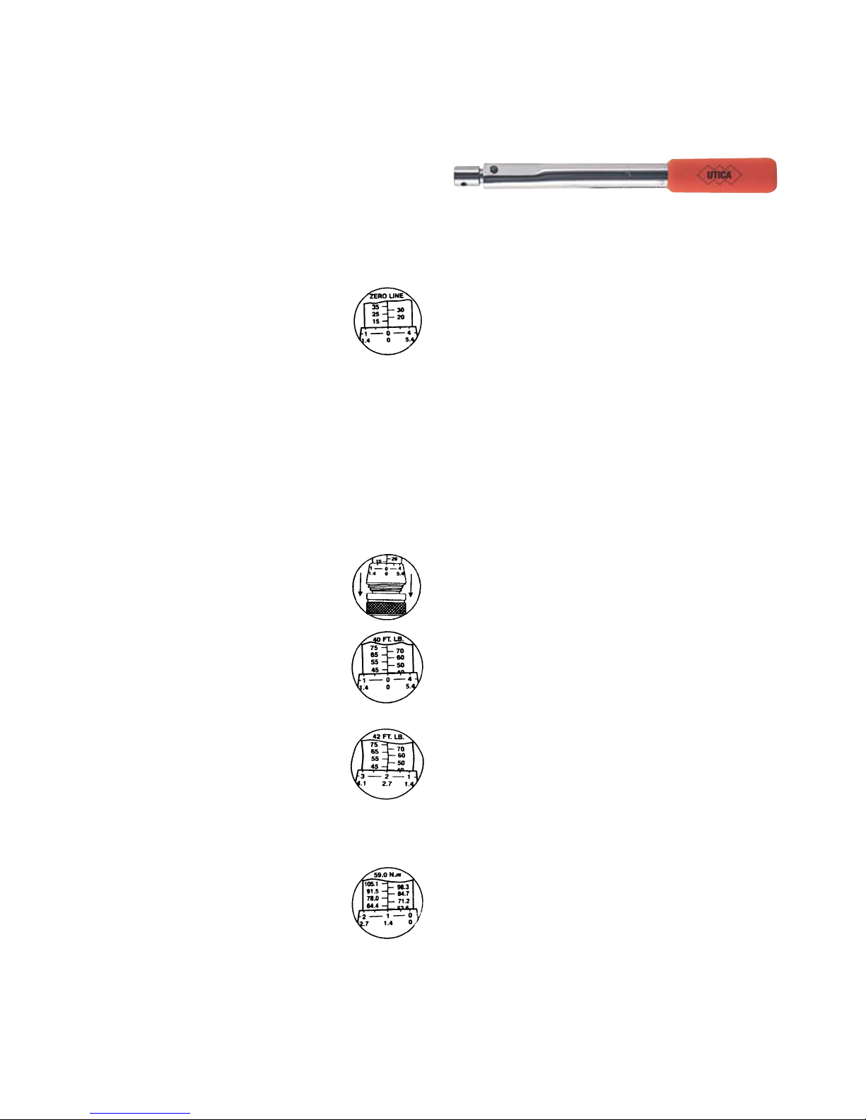
Setting the wrench is accomplished by considering all torque
settings as being made up of two parts, major scale plus ne
scale. Example: A torque setting of 42 ft-lbs would be 40 ft-lbs
on the major scale plus 2 ft-lbs on the ne scale.
These wrenches can be set to the desired torque as follows:
Grasp the locking collar between the1.
thumb and forenger and pull it toward the
wrench handle as far as possible. Hold it in
this position.
While holding the barrel of the wrench2.
securely in one hand, rotate the handle
until the major scale increment below the
torque desired is even with the edge of the
sleeve and the 0 increment on the sleeve is
in line with the zero line of the barrel.
Rotate the handle clockwise until the ne3.
scale torque increment desired lines up
with the zero line on the barrel. Release the
lock collar and the wrench is automatically
locked at the torque setting selected.
NOTE: The lock collar will not lock until an
increment line on the sleeve lines up with
the zero line on the barrel.
For Newton meter torque settings, use the4.
same procedure as described in steps 1-3
but using the Newton meter major scale on
the barrel and the ne scale on the sleeve.
The illustration shows a setting of 59.0
Nm. This can be accomplished by setting
57.6 on the major scale plus 1.4 on the
ne scale. NOTE: The ne scale values
have been rounded to the nearest whole
decimal.
Single Setting (Preset) Torque Wrenches:
These wrenches are designed so when torque is applied to a
fastener, it will momentarily release and signal by impulse and
audible click (or snap) that the preset torque value has been
reached.
The preset torque wrench is calibrated and sealed at the factory
to the torque value specied by the customer. Wrenches are
also available not preset or sealed when requested. Wrenches
preset at the factory are set to an accuracy tolerance of ±4%
of the specied torque value.
To Use:
Attach the appropriate adapter to the torque wrench and apply
to the application. Hold the torque wrench by the padded
handle and tighten the fastener. Apply force with a steady,
smooth action.
Do not apply force by holding any part of the wrench, other than
the padded handle. Do not use an extension or other lever aid
on the handle. When the torque setting is reached, the wrench
will momentarily release with a feel impulse and audible click
(or snap). The wrench will move through a small arc about
the pivot pin. At this point the set torque has been achieved
and force on the handle must be released. The wrench will
automatically snap back to it’s original position and is ready for
the next torque application.
CAUTION: Do not apply force after the wrench releases, clicks
(or snaps) at the set torque. If the fastener is over torqued,
loosen it and repeat the operation.
Always actuate the wrench a few times before use and after a
period when the wrench has not been in use.
To Calibrate or Re-Calibrate:
Calibration of this torque wrench should only be done on a1.
certied Torque Tester for the required torque range.
Using a suitable adapter, attach the wrench to the torque2.
tester.
Using a hex key, loosen the lock plug in the rear of the3.
handle.
Using a hex key (CHB models) or screwdriver (CHA4.
models), turn the adjusting plug clockwise to increase the
torque value or counter clockwise to decrease. Turn the
adjusting plug in small increments at a time. Actuate the
wrench by applying force on the handle and observe the
readings on the torque tester. Continue this procedure
until the desired torque setting has been reached.
Tighten the lock plug and recheck the torque reading on5.
the torque tester.
Make sure the seal washer is in place before applying any6.
liquid seal over the lock plug.
 Loading...