

UTICA BOILERS BC3D, BC3, BC4D, BC4 Installation, Operation & Maintenance Manual

BC Series
OIL-FIRED CAST IRON BOILER
INSTALLATION, OPERATION &
MAINTENANCE MANUAL
An ISO 9001-2008 Certified Company
Utica Boilers
2210 Dwyer Aven ue, Utica NY 13 504-4729
Phone: (315) 797-1310 • Fax: (866) 432-7329
e-mail: info@ecrinternational.com
web site : www . ecrinternationa l . com
P/N 2761101, Rev. A [02/2011]

H
SAFETY INFORMATION
TABLE OF CONTENTS
Ratings, Data, And Dimensions ...........................3
Installation Procedure .......................................4
Ventilation And Combustion Air ..........................5
Connecting Supply And Return Piping ..................7
Venting System Inspection & Installation ...........11
Oil Tank And Piping .........................................11
Electrical Wiring .............................................12
Thermostat Installation ...................................12
Oil Tank And Piping .........................................13
Normal Sequence Of Operation .........................15
Operating Instructions .....................................15
Maintenance Procedures ..................................17
Service Checklist ............................................18
Replacement Parts ..........................................19
Service Record ...............................................23
KEEP THIS MANUAL NEAR BOILER
RETAIN FOR FUTURE REFERENCE
SAFETY SYMBOLS
The following dened symbols are used throughout
this manual to notify the reader of potential hazards
of varying risk levels.
IMPORTANT: Read the following instructions
COMPLETELY before installing!!
WARNING
1. Keep boiler area clear and free from
combustible materials, gasoline and
other ammable vapors and liquids.
2. DO NOT obstruct air openings
to the boiler room.
3. Modication, substitution or
elimination of factory equipped,
supplied or specied components
may result in property damage,
!
personal injury or the loss of life.
TO ThE OWNER - Installation
4.
and service of this boiler must be
performed by a qualied installer.
TO ThE INSTALLER - Leave
5.
all instructions with the boiler
for future reference.
6. When this product is installed in the
Commonwealth of Massachusetts the
installation must be performed by a
Licensed Plumber or Licensed Gas Fitter.
DANGER
Indicates a hazardous situation which, if
!
not avoided, WILL result in death or serious
injury.
WARNING
Indicates a hazardous situation which, if
!
not avoided, could result in death or serious
injury.
CAUTION
Indicates a hazardous situation which, if not
!
avoided, may result in minor or moderate
injury.
NOTICE
Indicates information which should be
followed to ensure proper installation and
operation.
WARNING
All installations of boilers and venting
should be done only by a qualied expert
and in accordance with this manual.
!
Installing or venting a boiler or any other
gas appliance with improper methods or
materials may result in serious injury or
death due to re or to asphyxiation from
poisonous gases such as carbon monoxide
which is odorless and invisible.
Tested For 15 psi.
ASME
Working Pressure
2

RATINGS, DATA, AND DIMENSIONS
Min. Natural Draft
Chimney Size
Round Square
Pump Pressure
PSI
Nozzle Furnished
140PSIG
(5)
Boiler Model
Number
(1)
I=B=R Oil Burner
(2)
Input
G.P.h. MBh
(4)
heating
Capacity
(4)
MBh
I=B=R Net
Ratings
(3)(5)
Water MBh
A.F.U.E.
Rating
BC3D 0.77 107 93 75 86.0 6 8x8x15 140 .65 80B
BC3 1.00 140 118 103 80.0 6 8x8x15 140 .85 80B
BC4D 1.00 140 120 104 86.0 6 8x8x15 140 .85 80B
BC4 1.40 196 165 143 81.0 6 8x8x15 140 1.25 80B
NOTES:
1. Add sufx "T" to denote boiler with tankless heater.
2. I=B=R burner capacity is based on an oil heating value of 140,000 Btu/gal. and with 13% CO
3. Net ratings based on 170°F temperature in radiators and include 15% allowance for normal piping and pick-up load. Consult manufacturer for unusual piping and pick-up
temperatures.
4. Nozzle listed for use with Beckett Burner. When alternate burner is used, consult burner manufacturer's recommendations
5. For equivalent square feet of radiation, divide I=B=R output by 150.
6. MEA number for this series is 47-76E.
7. MEA number for R. W. Beckett Burner used in this boiler series are; AF/156-77-E, AFG/213-83-E, AFII 85/24-92-E, AFII 150/ 456-90-E.
8. Electrical service to be 120 Volts, 15 Amps, & 60 Hz.
TANK-LESS WATER HEATER CAPACITIES
Boiler
Model
Number
Firing
Rate
G.P.H.
Tankless
Heater
Number
Tankless Heater
Capacity Intermittent
Draw G.P.M.
Boiler
Water
Content
(Gallons)
BC3D 0.65 L-24 Available on request 6.7
BC3 1.00 L-24 3.25 6.7
.
2
STANDARD EQUIPMENT: Crated Boiler, Flush Jacket, Oil Burner, Target
Wall/Liner, Circulator-1.1/4", ASME Relief Valve, Theralitimeter Gauge,
Drain Cock, Wiring harness, Burner Electrical Disconnect, Plastic Cover,
Supply Tapping-2", Return Tapping-1.1/2", High Limit and Circulator Control,
Primary Control. For Tankless Heater Units-add Tanlkess Hot Water Coil,
Flow Restrictor and Triple Aquastat Relay.
(NOTE: For Tankless Heater units, add Tankless hot water coil, Flow Restrictor and
Triple Aquastat Relay.)
BC4D 1.00 L-24 3.25 8.2
BC4 1.40 L-24 4.00 8.2
Boiler No.
BC3 19" 9 ¾" 6.0" 8⅞
BC4 23" 11¾" 6.0" 12¾
DIMENSIONS
Length
of Flush
Jacket
Front of Jacket
to Center Line
of Flue Outlet
Flue
Outlet
Diameter
Coil to Back
-A- -B- -C- -D-
3
Tankless
of Jacket

INSTALLATION PROCEDURE
WARNING
!
Improper installation, adjustment,
The boiler shall be installed such that the oil ignition system components are protected from water (dripping, spraying, rain etc.) during appliance operation and service.
alteration, service or maintenance can
cause injury or property damage.
All installations must conform to the requirements of the
authority having jurisdiction. Such applicable requirements
take precedence over the general instructions of this
manual.
Where required by the authority having jurisdiction, the
installation must conform to the American Society of
Mechanical Engineers Safety Code for Controls and Safety
Devices for Automatically Fired Boilers, ANSI/ASME No.
CSD-1.
Locate boiler in front of nal position before removing
crate. Provide a solid level base as near chimney as
possible and centrally located with respect to the heat
distribution system as practical.
WARNING
!
Boiler may not be installed on combustible
ooring.
Allow 24 inches in the front, top and right hand side for
servicing and cleaning, or removing tankless water heating
coil.
FOR INSTALLATION ON NON-COMBUSTIBLE FLOORS ONLY
- The boiler must not be installed on carpeting or vinyl
ooring. Minimum clearances to combustible construction
are:
NOTE: Clearance for access should exceed fire protection
clearance.
Remove crate and plastic protective wrapper, inspect for
damage. All equipment is carefully manufactured, inspected
and packaged by experienced workers. Our responsibility
ceases upon delivery of the crated boiler to carrier in good
condition. Any claims for damage or shortage in shipment
must be led immediately against the carrier by consignee.
Move boiler to permanent position by sliding or walking.
TOP 24 IN.
FRONT 24 IN.
FLUE CONNECTOR 9 IN.
REAR 6 IN.
LEFT SIDE 6 IN.
RIGhT SIDE 24 IN.
When installed in a utility room, the door should be wide
enough to allow the largest boiler part to enter, or to permit
replacement of another appliance such as a water heater.
4
VENTS
CHIMNEY
OR
L TYPE VENT PIPE
VENT PIPE
BASEBOARD
12"
12"
VENTILATION AND COMBUSTION AIR
WARNING
!
Air openings to combustion area must not be obstructed. By following the instructions below,
adequate combustion air can be maintained.
COMBUSTION AIR REQUIREMENTS
(Minimum Opening Requirement)
Unconned Area* Conned Area**
Outside Inside Outside Combustion Air
BTU/hr
Input
Combustion Air 1 Sq.
In./5000 BTU/hr
(Step 4)
107,800 22 108 27 54
140,000 28 140 35 70
196,000 40 196 49 98
* A space whose volume is not less than 50 cubic feet per 1000 BTU/Hour of all appliances installed in that space (cubic feet of space = height x width x length)
** A space whose volume is less than 50 cubic feet per 1000 BTU/Hour of all appliances installed in that space (cubic feet of space = height x width x length)
Ventilation of boiler room must be adequate enough to
1.
provide sufcient air to properly support combustion
and venting.
When the boiler is located in an unconned space in a
2.
building of conventional construction frame, masonry
or metal, inltration normally is adequate to provide
air for combustion and ventilation. however, in any
building which has been altered to conserve energy
or to minimize inltration, the boiler area should
be considered as a conned space. If there is any
doubt, install air supply provisions for combustion
and ventilation in accordance with section 5.3, Air
for Combustion and Ventilation, of the NFPA 54 1988
code, the recommendations that follow, or applicable
provisions of the local building codes.
When the boiler is installed in an unconned space,
3.
in a building of unusually tight construction, air for
combustion and room ventilation must be obtained
from outdoors or from spaces freely communicating
with the outdoors. A permanent opening or openings
having a total free area of not less than 1 square inch
per 5,000 BTU per hour of total input rating of all
appliances shall be provided. Ducts may be used to
convey make-up air from the outdoors and shall have
the same cross-sectional area of the openings to which
they are connected.
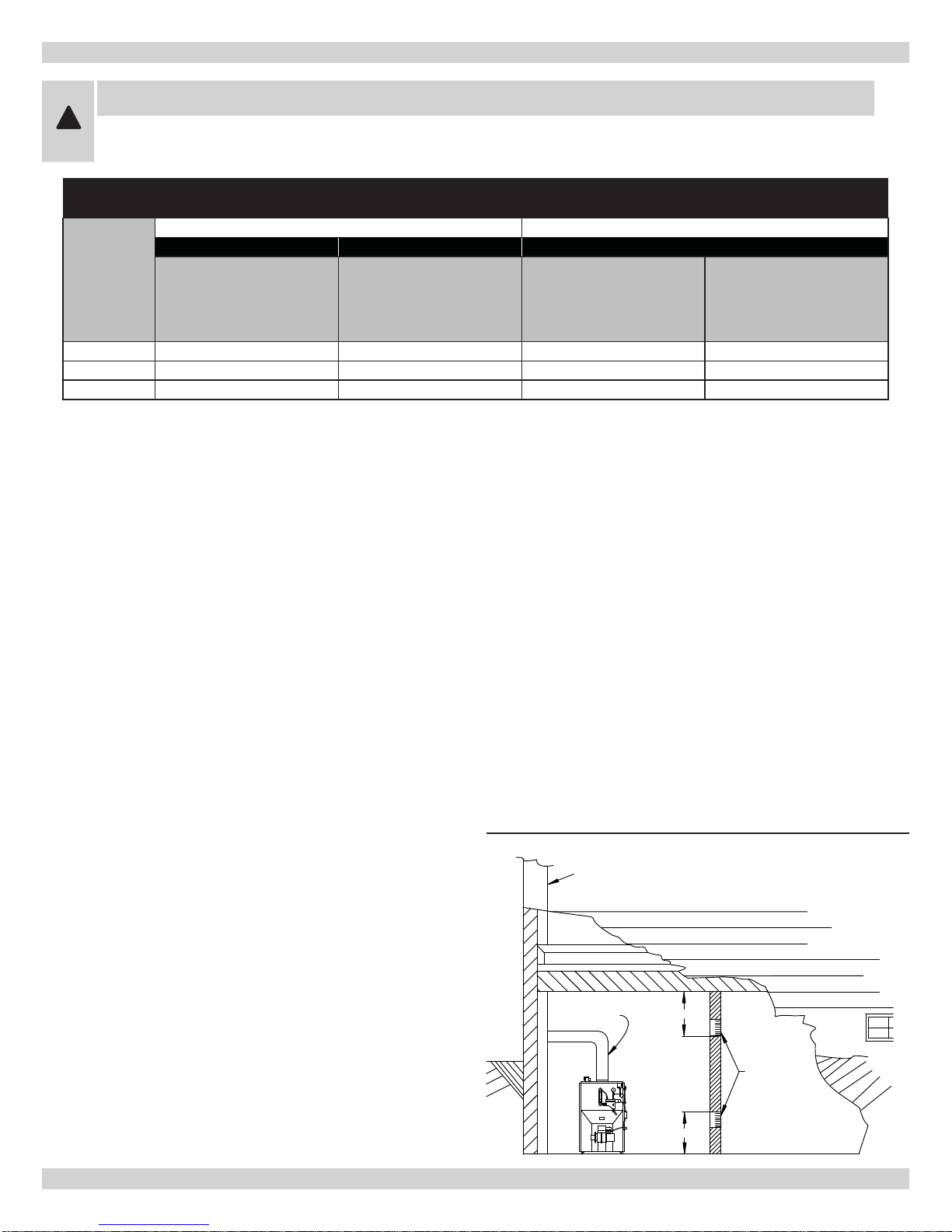
When air for combustion and room ventilation is from
4.
inside buildings, the conned space shall be provided
with two permanent openings, one starting 12 inches
from the top and one 12 inches from the bottom of the
enclosed space. Each opening shall have a minimum
free area of 1 square inch per 1,000 BTU per hour of
the total input rating of all appliances in the enclosed
space, but must not be less than 100 square inches.
These openings must freely communicate with the
interior areas having adequate inltration from the
outside. (Figure #3)
Combustion Air 1 Sq.
In./1000 BTU/hr
(Min. 100 Sq. In.)
When the boiler is installed in a conned space and
5.
all air is provided from the outdoors, the conned
space shall be provided with two permanent openings,
one commencing within 12 inches from the top and
one commencing 12 inches from the bottom of the
enclosure. The openings shall communicate directly, or
by ducts, with the outdoors or spaces (crawl or attic)
that freely communicate with the outdoors. One of the
following methods must be used to provide adequate
air for ventilation and combustion.
Figure #3
Vertical Ducts 1 Sq.
In./4000 BTU/hr
(Figures 2 & 3)
horizontal Ducts 1 Sq.
In./2000 BTU/hr
(Figure 4)
When directly communicating with the outdoors, A.
each opening shall have a minimum free area of 1
square inch per 4,000 BTU per hour of total input
rating of all equipment in the enclosure. (Figure
#4)
When communicating with the outdoors by means B.
of vertical ducts, each opening shall have a minimum free area 1 square inch per 4,000 BTU per
hour of total input rating of all appliances in the
enclosed space. (Figure #5)
5

VENTILATION AND COMBUSTION AIR
If horizontal ducts are used, each opening shall C.
have a minimum free area 1 square inch per 2,000
BTU per hour total input rating of all appliances in
the enclosed space. (Figure #6)
When ducts are used, they shall be of the same D.
cross sectional area as the free area of the area of
the openings to which they connect. The minimum
dimension of rectangular air ducts shall not be less
than 3 inches.
In calculating free area using louvers, grills or screens
6.
for the above, consideration shall be given to their
blocking effect. Screens used shall not be smaller than
1/4 inch mesh. If the free area through a design of
louver or grill is known, it should be used in calculating
the size opening required to provide the free area
specied. If the design and free area is not known, it
may be assumed that wood louvers will have 20-25%
free area and metal louvers and grills will have 60-75%
free area. Louvers and grills shall be xed in the open
position or interlocked with the boiler so that they are
opened automatically during boiler operation.
Figure #2
Figure #3
Figure #4
6

CONNECTING SUPPLY AND RETURN PIPING
Important: circulators in the following illustrations are
mounted on the system supply side, but mounting on the
system return side is also acceptable practice.
Figure #5
Figure #6
1.
Connect supply and return piping as suggested
in Figure # 5, below. When the boiler is used in
connection with refrigerated systems:
Chilled medium A. MUST BE IN PARALLEL with
boiler.
Use appropriate valves to prevent chilled medium B.
from entering heating boiler.
During the heating cycle open valves
2.
valves C and D.
7
A and B, close

CONNECTING SUPPLY AND RETURN PIPING
During heating cooling cycle open valves
3.
valves A and B.
Maintain a minimum clearance of one (1") inch to A.
hot water pipes. In air handling units where they
may be exposed to refrigerated air circulation, the
boiler piping system MUST be supplied with ow
control valves or other automatic means to prevent
gravity circulation of the boiler water during the
cooling cycle.
hot water boilers installed above radiation level must
4.
be provided with a low water device either as part of
the boiler or at the time of boiler installation.
When a boiler is connected to a heating system that
5.
utilizes multiple zoned circulators, each circulator must
be supplied with a ow control valve to prevent gravity
circulation.
* Reduced pressure back ow preventer must be
present under provisions required by the Environmental
Protection Agency, (EPA).
Bypass piping is an option which gives the ability to
6.
adjust the supply boiler water temperature to t the
system or condition of the installation. Although, this
method of piping is not typically required for baseboard
heating systems.
This method is used to protect systems using A.
radiant panels and the material they are encased
in from high temperature supply water from the
boiler. See gure 6 above.
C and D, close
This method is used to protect boilers from B.
condensate forming due to low temperature return
water. Generally noticed in large converted gravity
systems or other large water volume systems. See
Figure #7.
This method is used to protect boilers from C.
condensate forming as well as protecting the
heating system from high water temperature. See
Figure #8.
Note:
7.
B until desired system temperature is obtained.
Bypass loop piping must be the same size piping for the
8.
supply and return.
Typical installation using circulators is shown in
9.
#9.
Typical installation using zone valves is shown in
10.
Figure #10.
See
11.
water heater.
For further piping information refer to the I=B=R
12.
installation and piping guide.
When using bypass piping, adjust valves A and
Figure
Figure #11 for typical piping for domestic hot
Figure #7
8
 Loading...