

Utica Gas-fired Boiler User Manual
MGBMGB
MGB
MGBMGB
GAS FIRED BOILERS
FOR FORCED HOT WATER
UCTIONSUCTIONS
UCTIONSUCTIONS
UCTIONS
TING INSTRTING INSTR
TING INSTRTING INSTR
TING INSTR
Utica Boilers, • P.O. Box 4729 • Utica, NY 13504
AND OPERAAND OPERA
AND OPERAAND OPERA
AND OPERA
AL AL
AL AL
AL
TION MANUTION MANU
TION MANUTION MANU
TION MANU
ALLAALLA
ALLAALLA
ALLA
INSTINST
INSTINST
INST

TT
ABLE OF CONTENTSABLE OF CONTENTS
T
ABLE OF CONTENTS
TT
ABLE OF CONTENTSABLE OF CONTENTS
Safety Symbols & Warnings ........................................................................ Page 2
Installation Procedure .................................................................................. Page 3
Ventilation and Combustion Air .................................................................... Pages 4-6
Connecting Supply and Return Piping .......................................................... Pages 6-9
Vent Installation ........................................................................................... Page 9
Vent System modification ............................................................................ Page 10
Vent Damper Installation and Instructions .................................................... Page 11
Connecting Gas Service ............................................................................. Page 12
Electrical Wiring ........................................................................................... Page 13
Thermostat Installation ................................................................................. Page 13
Lighting Instructions ..................................................................................... Pages 13-16
Normal Sequence of Operation .................................................................... Page 16
General Instructions ..................................................................................... Pages 17-19
Checking Gas Input Rate to Boiler ............................................................... Pages 19-20
Replacement Parts Lists .............................................................................. Pages 20-25
Ratings and Data ......................................................................................... Page 26
Dimensions .................................................................................................. Page 27
KEEP THIS MANUAL NEAR BOILER
RETAIN FOR FUTURE REFERENCE
SERIES MGB
CAST IRON
GAS FIRED BOILERS
INSTALLATION MANUAL AND
OPERATION INSTRUCTIONS
C.S.A. Certified for Natural gas
or Propane
Published February 1989
Revised June 1998
Printed in USA
Made In USA
PAGE 1
Tested for 100 lbs.
ASME Working
Pressure
Safety SymbolsSafety Symbols
Safety Symbols
Safety SymbolsSafety Symbols
The following defined symbols are used throughout this manual to notify the
reader of potential hazards of varying risk levels.
DD
ANGERANGER
D
ANGER
DD
ANGERANGER
DANGER - Indicates an imminently hazardous situation which, if not avoided, WILL
result in death or serious injury.
WARNINGWARNING
WARNING
WARNINGWARNING
WARNING - Indicates a potentially hazardous situation which, if not avoided, COULD
result in death or serious injury
CACA
UTIONUTION
CA
UTION
CACA
UTIONUTION
CAUTION - Indicates a potential hazardous situation which, if not avoided, MAY result
in minor or moderate injury. It may also be used to alert against unsafe practices.
IMPORIMPOR
IMPOR
IMPORIMPOR
1. Keep boiler area clear and free from combustible materials, gasoline and other
flammable vapors and liquids.
2. DO NOT obstruct air openings to the boiler room.
3. Modification, substitution or elimination of factory equipped, supplied or specified
components may result in property damage, personal injury or the loss of life.
4. To the owner: Installation and service of this boiler must be performed by a qualified
installer.
5. To the installer: Leave all instructions with the boiler for future reference.
6. When this product is installed in the Commonwealth of Massachusetts the installation
must be performed by a Licensed Plumber or Licensed Gas Fitter.
VENTING SHOULD BE DONE ONLY BY A QUALIFIED EXPERT ANDVENTING SHOULD BE DONE ONLY BY A QUALIFIED EXPERT AND
VENTING SHOULD BE DONE ONLY BY A QUALIFIED EXPERT AND
VENTING SHOULD BE DONE ONLY BY A QUALIFIED EXPERT ANDVENTING SHOULD BE DONE ONLY BY A QUALIFIED EXPERT AND
IN ACCORDANCE WITH THE APPROPRIATE UTICA BOILERSIN ACCORDANCE WITH THE APPROPRIATE UTICA BOILERS
IN ACCORDANCE WITH THE APPROPRIATE UTICA BOILERS
IN ACCORDANCE WITH THE APPROPRIATE UTICA BOILERSIN ACCORDANCE WITH THE APPROPRIATE UTICA BOILERS
MANUAL. INSTALLING OR VENTING A BOILER OR ANY OTHERMANUAL. INSTALLING OR VENTING A BOILER OR ANY OTHER
MANUAL. INSTALLING OR VENTING A BOILER OR ANY OTHER
MANUAL. INSTALLING OR VENTING A BOILER OR ANY OTHERMANUAL. INSTALLING OR VENTING A BOILER OR ANY OTHER
GAS APPLIANCE WITH IMPROPER METHODS OR MATERIALS MAYGAS APPLIANCE WITH IMPROPER METHODS OR MATERIALS MAY
GAS APPLIANCE WITH IMPROPER METHODS OR MATERIALS MAY
GAS APPLIANCE WITH IMPROPER METHODS OR MATERIALS MAYGAS APPLIANCE WITH IMPROPER METHODS OR MATERIALS MAY
RESULT IN SERIOUS INJURY OR DEATH DUE TO FIRE OR TORESULT IN SERIOUS INJURY OR DEATH DUE TO FIRE OR TO
RESULT IN SERIOUS INJURY OR DEATH DUE TO FIRE OR TO
RESULT IN SERIOUS INJURY OR DEATH DUE TO FIRE OR TORESULT IN SERIOUS INJURY OR DEATH DUE TO FIRE OR TO
ASPHYXIATION FROM POISONOUS GASES SUCH AS CARBONASPHYXIATION FROM POISONOUS GASES SUCH AS CARBON
ASPHYXIATION FROM POISONOUS GASES SUCH AS CARBON
ASPHYXIATION FROM POISONOUS GASES SUCH AS CARBONASPHYXIATION FROM POISONOUS GASES SUCH AS CARBON
MONOXIDE WHICH IS ODORLESS AND INVISIBLE.MONOXIDE WHICH IS ODORLESS AND INVISIBLE.
MONOXIDE WHICH IS ODORLESS AND INVISIBLE.
MONOXIDE WHICH IS ODORLESS AND INVISIBLE.MONOXIDE WHICH IS ODORLESS AND INVISIBLE.
TT
ANT!ANT!
T
ANT! READ ALL INSTRUCTIONS BEFORE INSTALLING.
TT
ANT!ANT!
WARNING:WARNING:
WARNING:
WARNING:WARNING:
WARNING:WARNING:
WARNING:
WARNING:WARNING:
ALL INSTALLATIONS OF BOILERS ANDALL INSTALLATIONS OF BOILERS AND
ALL INSTALLATIONS OF BOILERS AND
ALL INSTALLATIONS OF BOILERS ANDALL INSTALLATIONS OF BOILERS AND
PAGE 2

INSTINST
INST
INSTINST
ALLAALLA
ALLA
ALLAALLA
TION PRTION PR
TION PR
TION PRTION PR
OCEDUREOCEDURE
OCEDURE
OCEDUREOCEDURE
WARNING: Improper installation, adjustment, alteration, service or maintenance
can cause injury or property damage.
1. The installation must conform to the requirements of the authority having jurisdiction or,
in the absence of such requirements, to the latest revision of the National Fuel Gas Code,
ANSI Z223. (Available from the American Gas Association, 8501 E. Pleasant Valley Road,
Cleveland, Ohio 44134). Reference should also be made to local gas utility regulations and
other codes in effect in the area in which the installation is to be made. When installed in
Canada: The latest revision of the CAN1-B149.1 and/or B149.2 Installation Codes for GasBurning Equipment and/or local codes.
2. Where required by the authority having jurisdiction, the installation must conform to
American Society of Mechanical Engineers Safety Code for Controls and Safety Devices For
Automatically Fired Boilers, ANSI/ASME No.CSD-1.
3. This boiler series is classified as a Category 1 and the vent installation shall be in
accordance with Part 7 of the National Fuel Gas Code noted above when installed in the
United States. In Canada refer to the CAN1-B149.1 and or B149.2 Installation Codes for
Gas-Burning Equipment. Also refer to applicable provisions of the local building codes.
4. This boiler has met safe lighting and other performance criteria with the gas manifold
and control assembly on the boiler per the latest revision of ANSI Z21.13/CGA 4.9.
5. The boiler shall be installed such that the gas ignition system components are protected
from water (dripping, spraying, rain, etc.) during appliance operation and service, (circulator
replacement, condensate trap, control replacement, etc.).
6. LOCATE BOILER on level, solid base as near the chimney as possible and centrally
located with respect to the heat distribution system as practical.
7. Allow 24 inches at the front and right side for servicing and cleaning.
8. When installed in a utility room, the door should be wide enough to allow the largest
boiler part to enter, or to permit replacement of another appliance such as a water heater.
9. FOR INSTALLATION ON NON-COMBUSTIBLE FLOORS ONLY . For installation
on combustible flooring special base part no. 325-2-8.00 must be used. The boiler can not
be installed on carpeting. Minimum clearances to combustible construction are:
TOP ........................................ 18 IN.
FRONT ................................... ALCOVE
FLUE CONNECTOR ...............6 IN.
REAR ...................................... 4 IN.
CONTROL SIDE .....................9 IN.
OTHER SIDE ..........................3 IN.
NOTE: Greater clearances for access should supersede fire protection clearances.
PAGE 3
VENTILAVENTILA
VENTILA
VENTILAVENTILA
WARNING:WARNING:
WARNING: AIR OPENINGS TO COMBUSTION AREA MUST NOT BE
WARNING:WARNING:
OBSTRUCTED. BY FOLLOWING THE INSTRUCTIONS BELOW, ADEQUATE
COMBUSTION AIR CAN BE MAINTAINED
TION & COMBTION & COMB
TION & COMB
TION & COMBTION & COMB
USTION USTION
USTION
USTION USTION
AIRAIR
AIR
AIRAIR
COMBCOMB
COMB
COMBCOMB
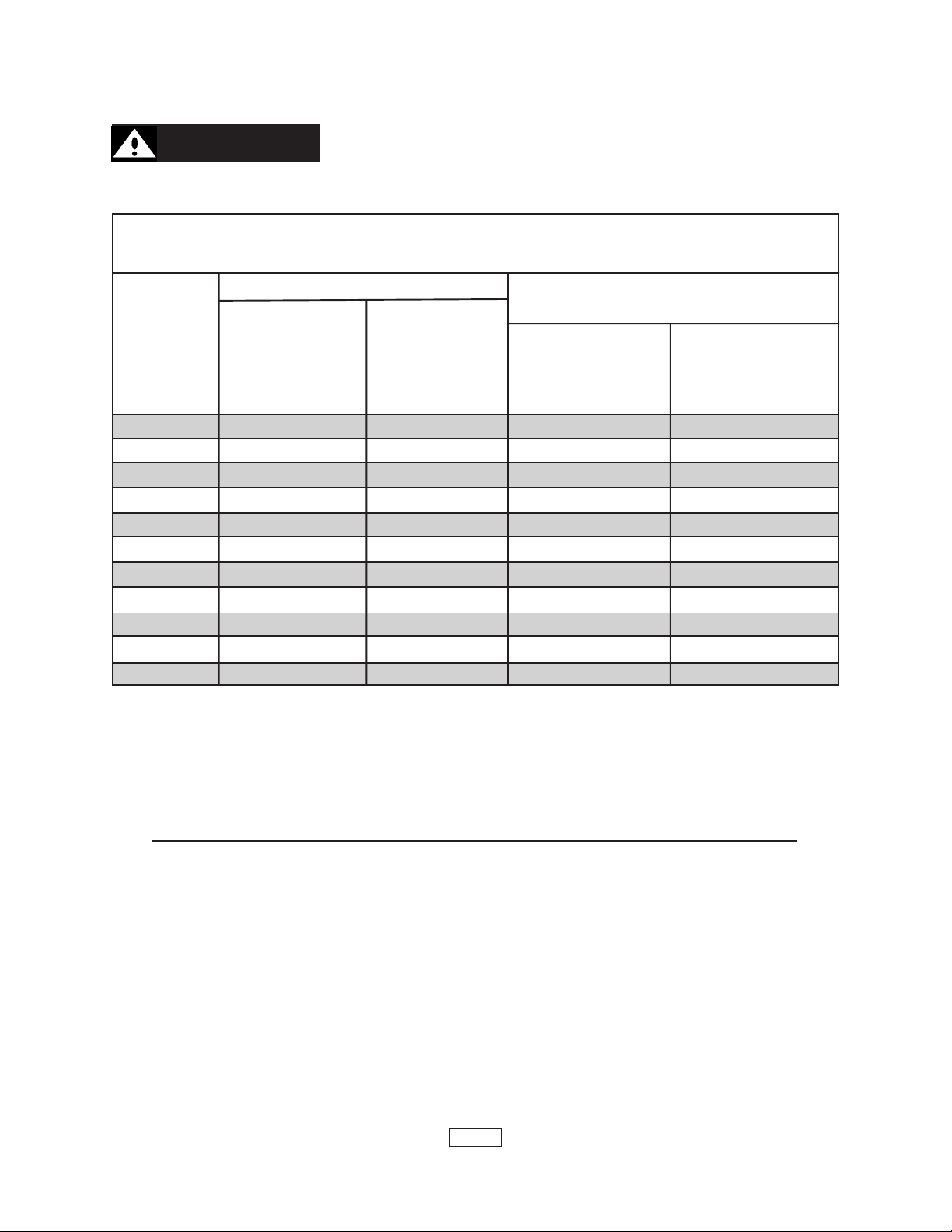
OUTSIDE INSIDE OUTSIDE COMBUSTION AIR
MODEL COMBUSTION COMBUSTION VERTICAL HORIZONTAL
NUMBER AIR 1 SQ. IN AIR 1 SQ. IN. DUCTS DUCTS
MGB /5000 BTU/HR /1000 BTU/HR 1 SQ. IN. 1 SQ. IN.
(SEE FIG. 4) (SEE FIG. 3) /4000 BTU/HR /2000 BTU/HR
MGB 38 8 100 10 19
MGB 50 10 100 13 25
MGB 75 15 100 19 38
MGB 100 20 100 25 50
MGB 125 25 125 32 63
MGB 150 30 150 38 75
MGB 175 35 175 44 88
MGB 200 40 200 50 100
MGB 225 45 225 57 113
MGB 275 55 275 69 138
MGB 300 60 300 75 150
USTION USTION
USTION
USTION USTION
(MINIMUM SQUARE INCHES OPENING)
**
*UNCONFINED AREA
**
AIR REQAIR REQ
AIR REQ
AIR REQAIR REQ
UIREMENTSUIREMENTS
UIREMENTS
UIREMENTSUIREMENTS
****
**CONFINED AREA
****
**
* Unconfined area: A space whose volume is not less than 50 cubic feet per
**
1000 BTU per hour of all appliances installed in that space (cubic feet of space = height x
width x length).
****
** Confined area: A space whose volume is less than 50 cubic feet per 1000 BTU
****
per hour of all appliances installed in that space (cubic feet of space = height x width x
length).
1. Ventilation of the boiler room must be adequate to provide sufficient air to properly
support combustion per the latest revision of the National Fuel Gas Code, ANSI Z223.1
section 5.3.
2. When a boiler is located in an unconfined space in a building or conventional construction
frame, masonry or metal building, infiltration normally is adequate to provide air for
combustion and ventilation. However, if the equipment is located in a building of unusually tight
construction (See the national Fuel Gas Code, Ansi Z223.1 section 1.7), the boiler area
should be considered as a confined space. In this case air for combustion and ventilation shall
be provided according to part 5 on page 5. If there is any doubt, install air supply provisions
in accordance with the latest revision of the National Fuel Gas Code.
3. When a boiler is installed in an unconfined space, in a building of unusually tight
PAGE 4
construction, air for combustion and ventilation must be obtained from outdoors or from
spaces freely communicating with the outdoors. A permanent opening or openings having a
total free area of not less than 1 square inch per 5,000 BTU per hour of total input rating of
all appliances shall be provided. Ducts may be used to convey makeup air from the outdoors
and shall have the same cross-sectional area of the openings to which they are connected.
4. When air for combustion and ventilation is from inside buildings, the confined space shall
be provided with two permanent openings, one starting 12 inches from the top and one 12
inches from the bottom of the enclosed space. Each opening shall have a minimum free area
of 1 square inch per one thousand (1000) BTU per hour of the total input rating of all appliances
in the enclosed space, but must not be less than one hundred (100) square inches. These
openings must freely communicate directly with other spaces of sufficient volume so that the
combined volume of all spaces meets the criteria for an unconfined space.
5. When the boiler is installed in a confined space and all air is provided from the outdoors
the confined space shall be provided with one or two permanent openings according to
methods A or B. When ducts are used, they shall be of the same cross sectional area as the
free area of the area of the openings to which they connect. The minimum dimension of
rectangular air ducts shall be not less than 3 x 3 inches or 9 square inches.
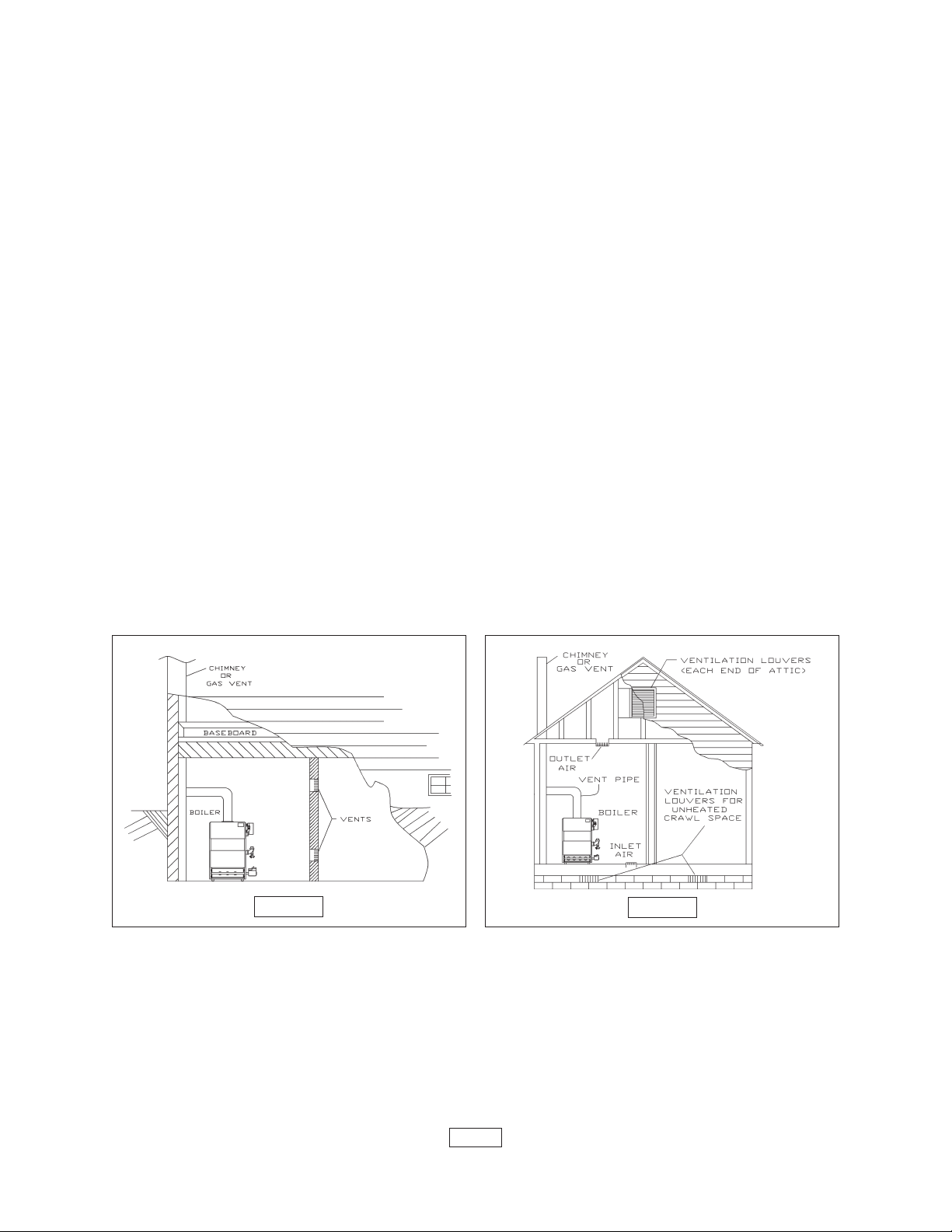
A. When installing two openings, one must commence within 12 inches from the top and
the other within 12 inches from the bottom of the enclosure. The openings shall communicate
directly, or by ducts, with the outdoors or spaces (crawl or attic) that freely communicate with
the outdoors. One of the following methods must be used to provide adequate air for
ventilation and combustion.
1. When directly communicating with the outdoors, each opening shall have a
minimum free area of 1 square inch per 4,000 BTU per hour of total input rating of all
equipment in the enclosure. See figure 2 below.
FIGURE 1
FIGURE 2
2. When communicating with the outdoors by means of vertical ducts, each
opening shall have a minimum free area 1 square inch per 4,000 BTU per hour of total input
rating of all appliances in the enclosed space. See figure 3 on page 6.
3. If horizontal ducts are used, each opening and duct shall have a minimum free
area 1 square inch per 2,000 BTU per hour of total input rating of all appliances in the enclosed
space. See figure 4 on page 6.
B. One permanent opening, commencing within 12 inches of the top of the enclosure,
PAGE 5
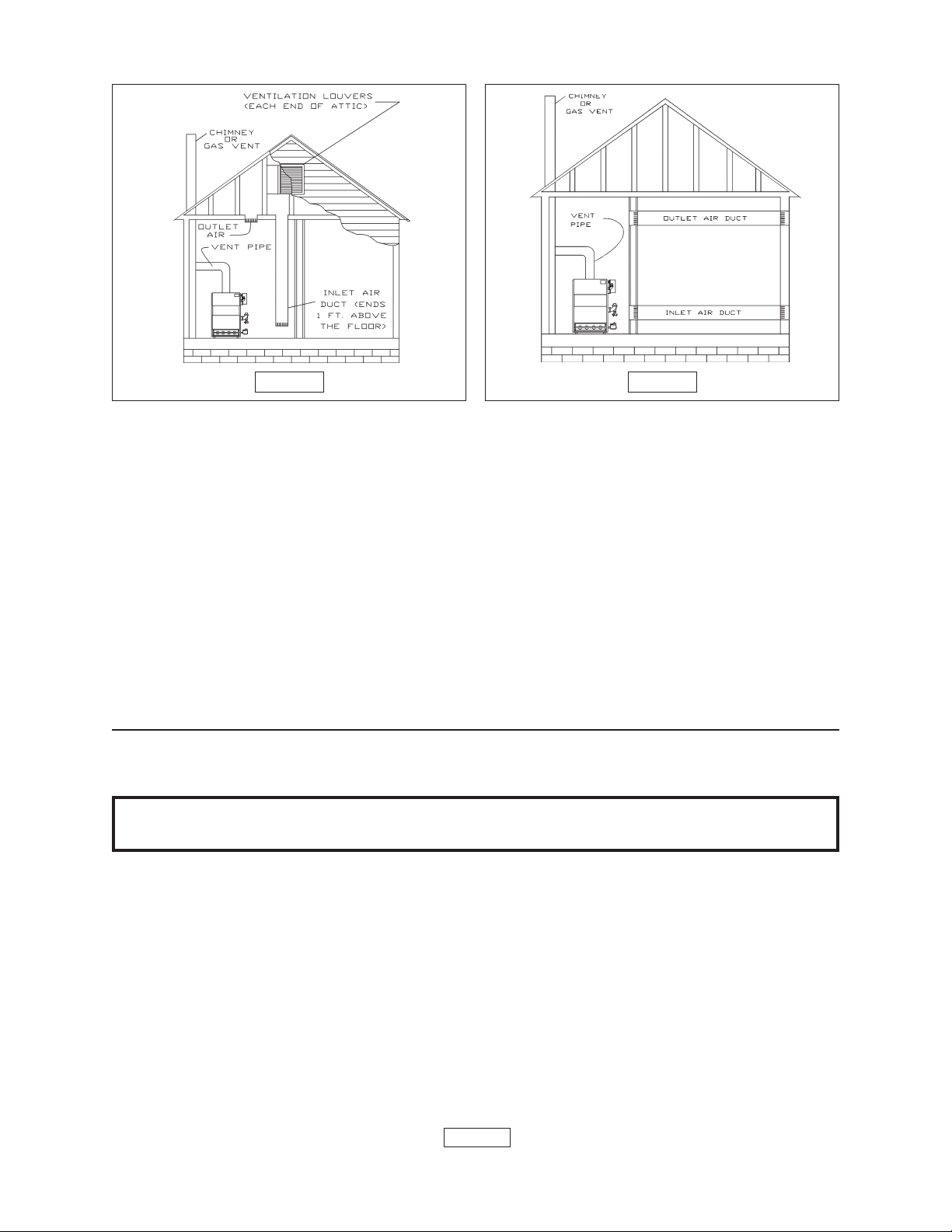
FIGURE 3 FIGURE 4
shall be permitted where the equipment has clearances of at least 1 inch from the sides, 1
inch from the back, and 6 inches from the front of the boiler. The opening shall directly
communicate with the outdoors or shall communicate through a vertical or horizontal duct to
the outdoors or spaces (crawl or attic) that freely communicate with the outdoors. The
openings must have a minimum free area of 1 square inch per 3000 Btu per hour of the total
input rating of all equipment located in the enclosure. The free area must be no less than the
sum of the areas of all vent connectors in the confined space.
6. In calculating free area using louvers, grilles or screens for the above, consideration shall
be given to their blocking effect. Screens used shall not be smaller than 1/4 inch mesh. If the
free area through a design of louver or grill is known, it should be used in calculating the size
opening required to provide the free area specified. If the design and free area is not known,
it may be assumed that wood louvers will have 20-25% free area and metal louvers and grilles
will have 60-75% free area. Louvers and grilles should be fixed in the open position or
interlocked with the boiler so they are opened automatically during the boiler operation.
CONNECTING SUPPLCONNECTING SUPPL
CONNECTING SUPPL
CONNECTING SUPPLCONNECTING SUPPL
IMPORTANT: Circulators in the following illustrations are mounted on the system supply
side, but mounting on the system return side is also acceptable practice.
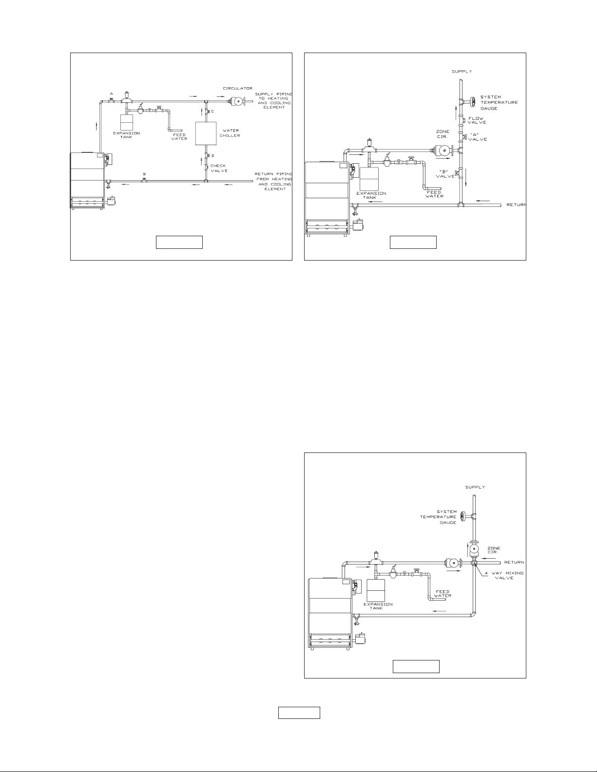
1. Connect supply and return piping as suggested in figure 5 on page 7, when the boiler
is used in connection with refrigerated systems.
A. The chilled medium
B. Use appropriate valves to prevent the chilled medium from entering the
heating boiler.
a. During heating cycle open valves A and B, close valves C and D.
b. During cooling cycle, open valves C and D, close valves A and B.
C. Maintain a minimum clearance of one inch to hot water pipes.
2. When the boiler is connected to heating coils located in air handling units where they may
be exposed to refrigerated air circulation, the boiler piping system MUST BE supplied with
flow control valves or other automatic means to prevent gravity circulation of the boiler water
during the cooling cycle.
MUST BE PIPED IN PARALLELMUST BE PIPED IN PARALLEL
MUST BE PIPED IN PARALLEL with the boiler.
MUST BE PIPED IN PARALLELMUST BE PIPED IN PARALLEL
Y Y
AND RETURN PIPINGAND RETURN PIPING
Y
AND RETURN PIPING
Y Y
AND RETURN PIPINGAND RETURN PIPING
PAGE 6
BYPASS PIPING
FIGURE 5
FIGURE 6
3. Hot water boilers installed above radiation level must be provided with a low water cutoff device.
4. When a boiler is connected to a heating system that utilizes multiple zoned circulators,
each circulator must be supplied with a flow control valve to prevent gravity circulation.
5. Hot water boilers and system must be filled with water and maintained to a minimum
pressure of 12 pounds per square inch.
6. Bypass piping is an option which gives the ability to adjust the supply boiler water
temperature to fit the system or the condition of the installation. This method of piping, however,
is not typically required for baseboard heating systems. Typical installations where bypass
piping is used are as follows:
A. This method is used to protect
boilers from condensation forming due to low
MIXING VALVE PIPING
temperature return water. Generally noticed in
large converted gravity systems or other large
water volume systems. See figure 6 above.
B. These methods are used to protect
systems using radiant panels and the material
they are encased in from high temperature
supply water from the boiler and protect the
boiler from condensation. See figure 7 at
right and 8 on page 8.
NOTE 1: When using bypass piping, adjust
valves A and B until desired system
temperature is obtained.
NOTE 2: Bypass loop must be same size
piping as the supply and return piping.
PAGE 7
FIGURE 7
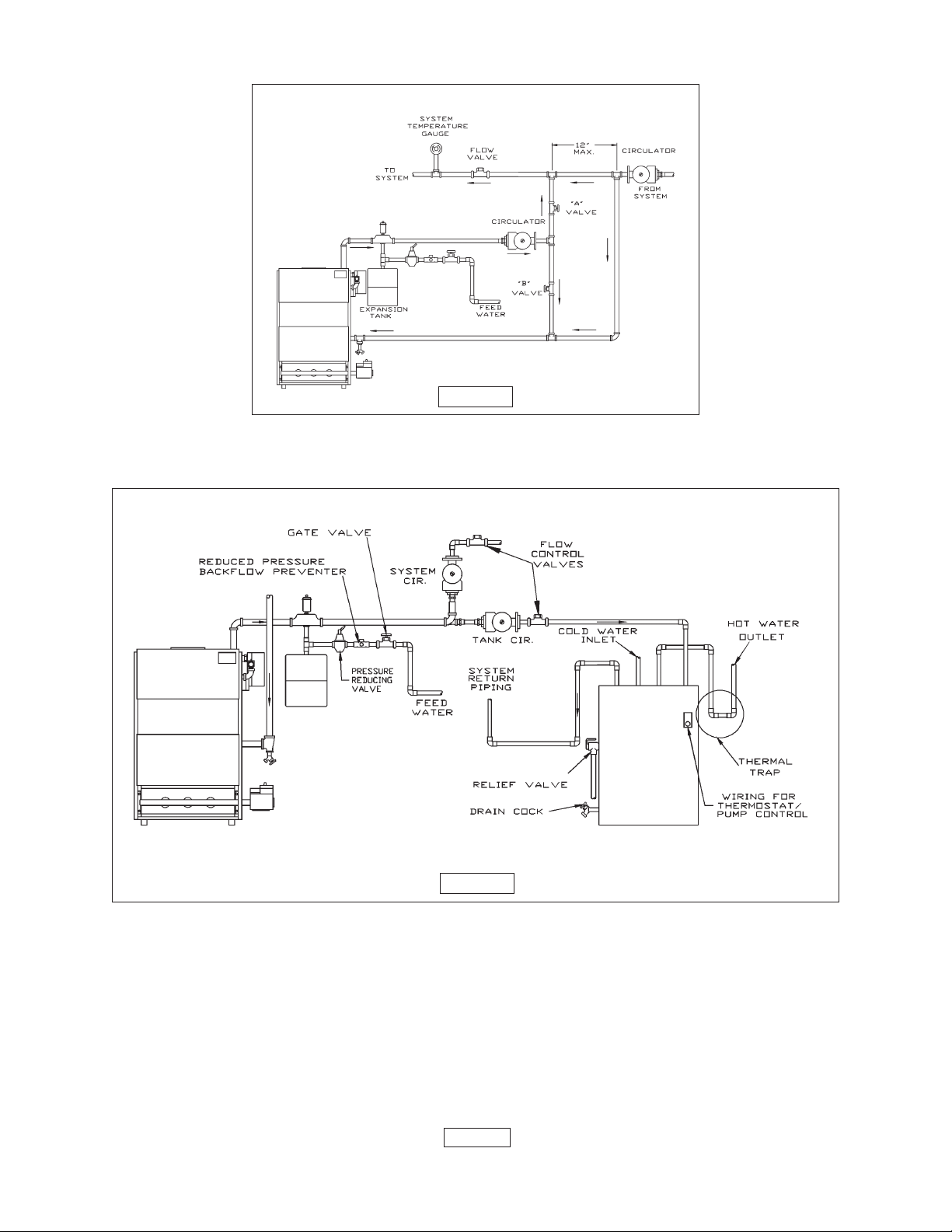
PRIMARY SECONDARY PIPING WITH BY PASS
FIGURE 8
7. Installation using circulators is shown in figure 9 below.
FIGURE 9
8. Installation using zone valves is shown in figure 10 on page 9.
9. For further piping information refer to the I=B=R Installation and Piping Guide.
PAGE 8
 Loading...