

Page 1

Quick setup wizard
24 Ports Gigabit SFP(10G SFP uplink)
L3 Managed Switch
Page 2

Content
1
Product Introduction
1
1.1 Overview
1
1.2
Board Diagram
1.3
2
Product Feature
3
2
Installation
4
2.1 Shipping List
2.2
Installation Precautions
4
2.2.1 Safety Precautions
4
2.2.2 Installation Requirements
5
2.3
Installation Way
2.3.1 Rack Installation
2.3.2 Workbench Installation
2.3.3 Wall-hung Installation
3 Function Configuration Guide
3.1
Computer Requirements
3.2 Set up Network Connection
3.2.1 Set Static IP for the Management Computer
3.2.2
Confirm the Network Connection by Ping Command
12
3.2.3
Cancel the Proxy Server
12
1.4
Specification
1
2.2.3
The Requirements of Electromagnetic Environment
5
3.3
Web Page Configuration Guide
13
3.3.1 Start and Login
13
3.3.2 Change Language
14
4
6
7
7
10
10
10
10
6
2.4
Cable Connection
2.4.1 Device Connection
2.4.2 Configuration Cable Connection
2.4.3 Power Cable Connection
9
9
9
9
Page 3
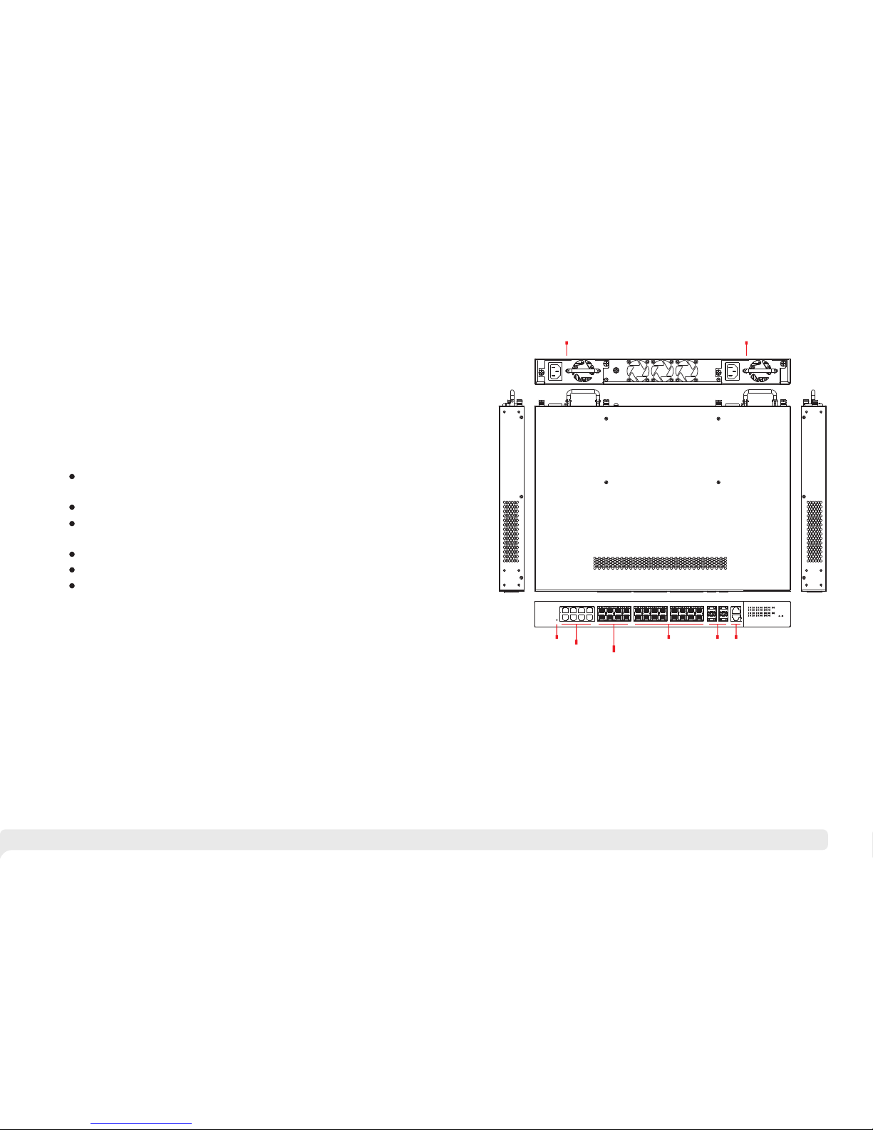
1.3 Diagram Board
1 Product Introduction
1.1 Overview
The 2 4 Gigab it port s manag ed Ethe rnet sw itch, w hich pr ovide 2 4 Gigab it SFP
slo ts , 8 * 10/1 00/10 00 RJ45 c ombo po rts , and 4 * 1000/ 10G upl ink SFP s lot s .
The p roduc t suppo rt Web la yer -3 ne two rk ma nag eme nt . Pr odu cts a re wi del y
use d in secu rity su rveil lance , netwo rk engi neeri ng proj ects an d so on.
1.2 Product Feature
Pro vide 24 G igabi t SFP slo ts , 8* 10/ 100/1 000 RJ4 5 combo p orts, 4*
100 0/10G u plink S FP slot s ;
Pro vide we b-bas ed laye r 3 netwo rk mana gemen t ;
Sup port hi gh-sp eed dat a forwa rding , very su itabl e for lar ge flow o f video d ata
for wardi ng in sec urity s urvei llanc e;
Sup port fa st-ri ng ,sel f-hea ling in 2 0ms Min .
Sup port 2 hi gh perf erman ce powe r modul es;
Qui ck Inst allat ion, si mple op erati on, con venie nt for wa ll/de sk/ra ck
ins talla tion.
1
2
Combo gigabit SFP
Combo gigabit RJ45
Gigabit SFP
10G SFP+
OOB
Console
Init key
Power module1
Power module2
AC Power input
AC Power input
Page 4
Pro ducts a re subj ect to ch ange wi thout p rior no tice.
3 4
2 Installation
Ant i-counterfeiting la bel i s att ach ed to sw itc h's c ove r. Pro duc t dam age
cau sed by un autho rized d isass embly i s not cov ered un der war ranty.
Caution
2.1 Package List
2.2 Installation Precautions
To avo id devi ce dam age or per son al inj ury by imp rop er use, pl eas e rea d the
fol lowin g preca ution s caref ully.
P
con tact yo ur loca l deale r.
lea se chec k the f oll owi ng it ems be for e ins tal lat ion , if an y mis sin g, pl eas e
Thi s i s the leve l A prod uct , whic h may caus e radi o dist urb anc e in livin g
env ironm ent. Use rs may need to ta ke ap pro pri ate and eff ect ive mea sur es
to so lve the p roble m.
Item Name
Quantity
Unit
1
Switch
pc
2
AC Power Line
pc
4
Accessory
1
set
3
Quick setup wizard
1
pc
2.2.1 Safety Precautions
Instruction
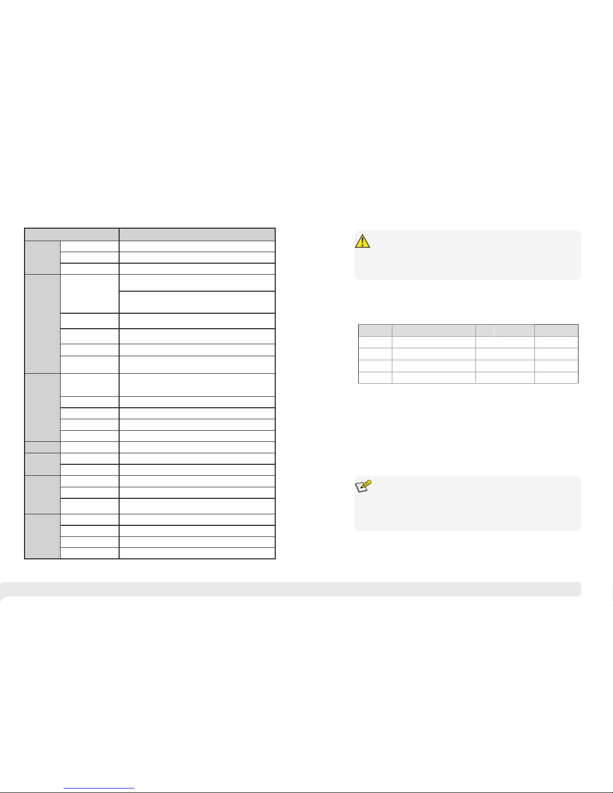
1.4 Specification
Ite m
Des cript ion
Pow er
Pow er Supp ly
AC po wer mod ule(r edund ant pow er, supp ort 2 mod ules)
Volt age Ran ge
AC ~100 240 V 50/60 Hz
Con sumpt ion
60W
Net work
Con necto r
Eth ernet Po rt
1~8 p orts: 10/ 100/ 100 0Mbps R J45 Auto -MDI/ MDI-X o r 1000B ase-X S FP
9~2 4 ports :100 0Base -X SFP
25~ 28 port s:10 00/10 GEBas e-X SFP +
If se t it 1000 Base- X,setup t he "po rts set tings " o n Web
man ageme nt
Ini t key
Sho rt pres s resta rt
>5s p ress re cover y to defa ult
OOB p ort
1*1 0/100 Base- TX RJ45 (only t o web man ageme nt)
Def ault IP :192. 168.1 .200 na me :adm in pass word :a dmin
Con sole po rt
1*RJ45-R232 serial port (115200,8,N,1)
Tran smis sion Di stanc e
RJ4 5 ports :100 m
SFP p orts: d epend o n SFP modu le
Net work Sw itch
Net work St andar d
IEE E802. 3, IEEE 802. 3u, IEEE 802. 3ab ,IEEE 802. 3z, IEE E802. 3
X, IEEE 8 02.1 Q,IE EE 802. 1p, IEE E 802. 3ad, IEEE8 02.3a e
Swi tch Cap acity
128 Gbps
Pac ket Buf fer
12M b
Pac ket For wardi ng Rate
95. 2Mpps
MAC Ad dress
16K
Man ageme nt
Man ageme nt
Web /CLI Ma nagem ent L2/ L3
Pro tecti on
ESD
6KV /8KV Pe r:IE C6100 0-4-2
Lig hting P rotec tion
6KV P er: IEC 61000 -4-5
Env ironm ental
Wor king Tempe ratur e
-10 ~50℃℃
Sto rge Tempe ratur e
- ℃~40 85℃
Hum idity (non-
con densi ng)
0 95%~
Mec hanic al
Dim ensio n(LxW xH)
442 mm×32 0mm×4 4mm
Mat erial
Met al
Col or
Bla ck
Wei ght
5. 65kg
1
1
Att entio n: the p ack age o nly co mes w ith one mo dul e ,if n ecess ary, you ca n
pur chase a nothe r one by yo ursel f.
Page 5
5 6
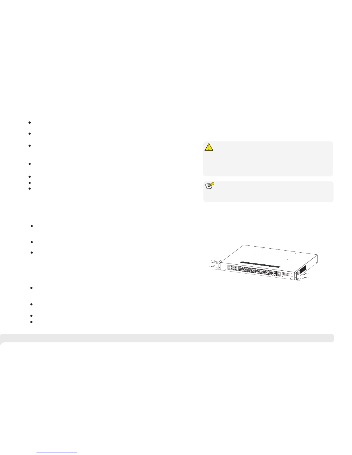
Figure 2-1 Install hangers diagram
Pul l out the pow er p lug be for e cl ean ing the swi tch . D o no t us e we t cloth no r
liq uid to wi pe or was h the swi tch;
Do n ot le ave t he sw itc h clo se t o wat er or w et pl ace so as t o pre ven t water o r
dam pness f rom ent ering i nto the s witch ;
Mak e sur e the sw itc h wor k in a cle an env iro nme nt. E xce ssi ve dus t may
cau se ele ctr ost ati c ads orp tio n, wh ich w ill affe ct th e equi pme nt li fe an d cau se
com munic ation f ailur e;
The swit ch wil l work nor mal ly und er the corr ect volt age . P lea se ens ure the
vol tage in dicat ed on the s witch c orres ponds t o the pow er volt age;
To a voi d t he d ang er of elec tri c s hoc k, plea se do not ope n the swit ch case .
Do no t open th e switc h case ev en if the s witch i s power ed off;
The acce sso rie s ( inc lud ing but n ot lim ite d to powe r c abl es, etc .), whic h ca n
be us ed for th e switc h only, i s prohi bited f or othe r appli catio ns.
The de vic e shou ld wor k in indo or env iro nme nt to avo id thu nde r strok e. It is
imp ortan t to obe y the fol low ing re quire ments no ma tte r you inst all it in th e
cab inet or o n the wor kbenc h direc tly:
Eno
u
gh
s
p
a
ce
(
la
rg
e
r th
an
1
0
cm)
for
air
o
u
tl
et
s
o as
to
fa
cil ita
te t
he
h
eat
i
n
g
di
ss
i
p
atio
n
;
G
o
od v
e
n
til a
ti
on s
y
ste
m
f
o
r
c
ab
i
n
ets a
n
d
wo
rk
ben
c
h
i
s pre
fe
r
red
;
Ens
ur
e th
e Ca
b
in
e
t
a
n
d wo
rkb
en
c
h
i
s
stu
rd
y
e
n
o
u
g
h t o s
u
pp
o
r
t
t
h
e
s
witch
an
d i
t
’s
ac
c
es
so
rie
s
’s
wei g
h
t
;
Ca
b
in
e
t
a
n
d
wo
rk
b
en
c
h with g
o
o
d
g
rou
n
din
g is pr e
f
e
r
re
d
.
Whe n it is w ork ing , t he swi tch may be af fec ted by ex terna l int erf ere nce outs ide
the syst em thr oug h t he way s o f ra diati on an d c ond uct ion . P lea se pay atte nti on
to th e follo wings :
AC p owe r sup ply i s TN sy ste m, so it is n ece ssa ry to u se si ngle p has e pow er
soc ket (PE) which can pro tec t grou nd wir e so that the fi lte r ci rcu it can
eff ect ive ly fi lte r out t he po wer g rid d ist urb anc es;
The swi tch sho uld wor k fa r aw ay f rom h igh-p ower r adi o tr ans mit ter s, r ada r
tra nsmit ters, h igh-f reque ncy dev ices;
Use e lectr omagn etic sh ieldi ng if nec essar y, such a s shiel ded cab le;
Int erfac e cabl es s hou ld b e ar ran ged ind oor rat her tha n ou tdo or t o pr eve nt
ove r-vol tage or o ver-c urren t damag e to the si gnal po rt.
2.2.2 Installation Requirements
2.2.3 The Requirements of Electromagnetic Environment
The diag ram is f or re feren ce onl y, the products a re subject t o actual
pro duct.
2.3 Installation Way
2.3.1 Rack Installation
The re are 3 in stall ation w ays: ra ck, wor kbenc h and ins talla tion. wal l-hun g
Ins talla tion pr ocess :
(1) C heck ra ck with g ood gro undin g and sta bilit y;
(2) U se scre ws to fit h anger s at the de vice bo ard sid e;
Ple ase p ull ou t th e pow er p lug be fore in sta lli ng or mo vin g t he s wit ch.
Gro undin g and an ti- lig hte nin g can g rea tly inc rea se th e pro tec tio n lev el of the
swi tch. please con nec t the gro und ing t erm ina l to t he e art h are a by us ing at
lea st wire 2 0.
Caution
Instruction
(3) Pu t the dev ice on the ra ck’ s bra cke t a nd mov e the rack al ong th e slot to
pro per pos ition ;
(4) Use scre ws to f it the ins tal lat ion han ger at rack’s fixe d s lot , mak e s ure the
dev ice is in stall ed at rac k’s bra cke t ste adi ly.
Page 6
7 8
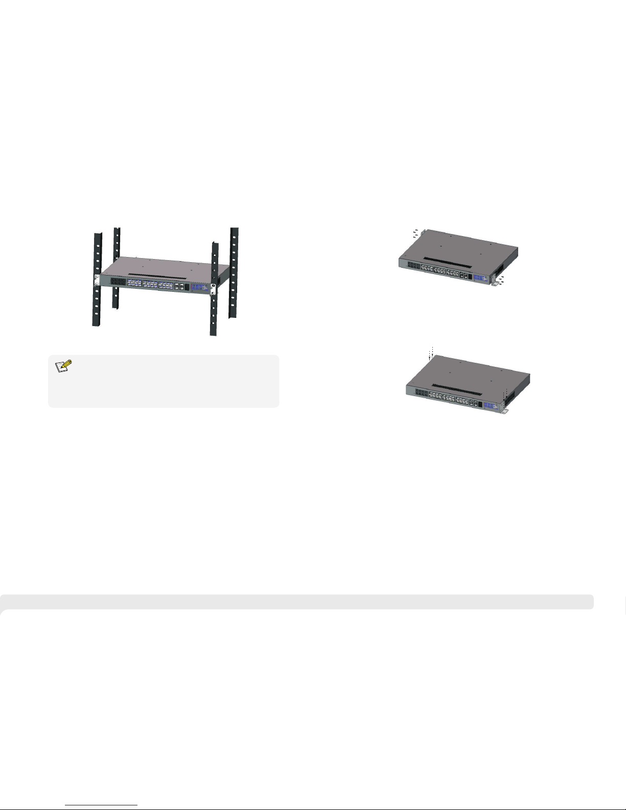
Figure 2-2 Install switch to the rack
Thi s prod uct ’s f ixi ng h ang ers are jus t to fix the swi tch rather t han su pport
it. Us e b racke ts und er the de vic e ( fix ed to the ra ck) to su ppo rt swi tch
whe n insta ll the sw itch to t he rack .
Instruction
2.3.2 Workbench Installation
2.3.3 Wall-hung Installation
You a lso can pu t th e pr odu ct o n cl ean , s teady ve rti cal wa ll. In sta lla tio n
pro cedur e is belo w:
(1) Use the screws to fix the hang ers ;
You c an p ut th is pro duc t on cle an, sta ble , gr oun ded wor kbe nch . The ins tal lat ion
pro cedur e as belo w:
(1 )C are ful ly pu t the de vic e ups ide d own , cle an the g roo ves o n the ch ass is
bac kplan e with so ft clot h to make s ure the re is no oi l or dust i n it;
(2 )R emo ve th e sti cke rs on t he fo ot pa d, pa ste t he fo ot pa d in ba ckp lan e gro ove ;
(3 )C are ful ly pu t the d evi ce up rig ht on t he wo rkb enc h.
Figure 2-3 Hangers installation diagram
Figure 2-4 Fix the switch on wall
(2) Dril l ho les o n t he s trong posi tio n of wall and then dri ve the rubb er p lug into
the h ole;
(3) Dri ve t hes e sc rew s in to t he h ole for the rac k an d fi x th e pr odu ct by aim ing at
the r ubber p lug .
Page 7
9 10
2.4 Cable Connection
2.4.1 Device Connection
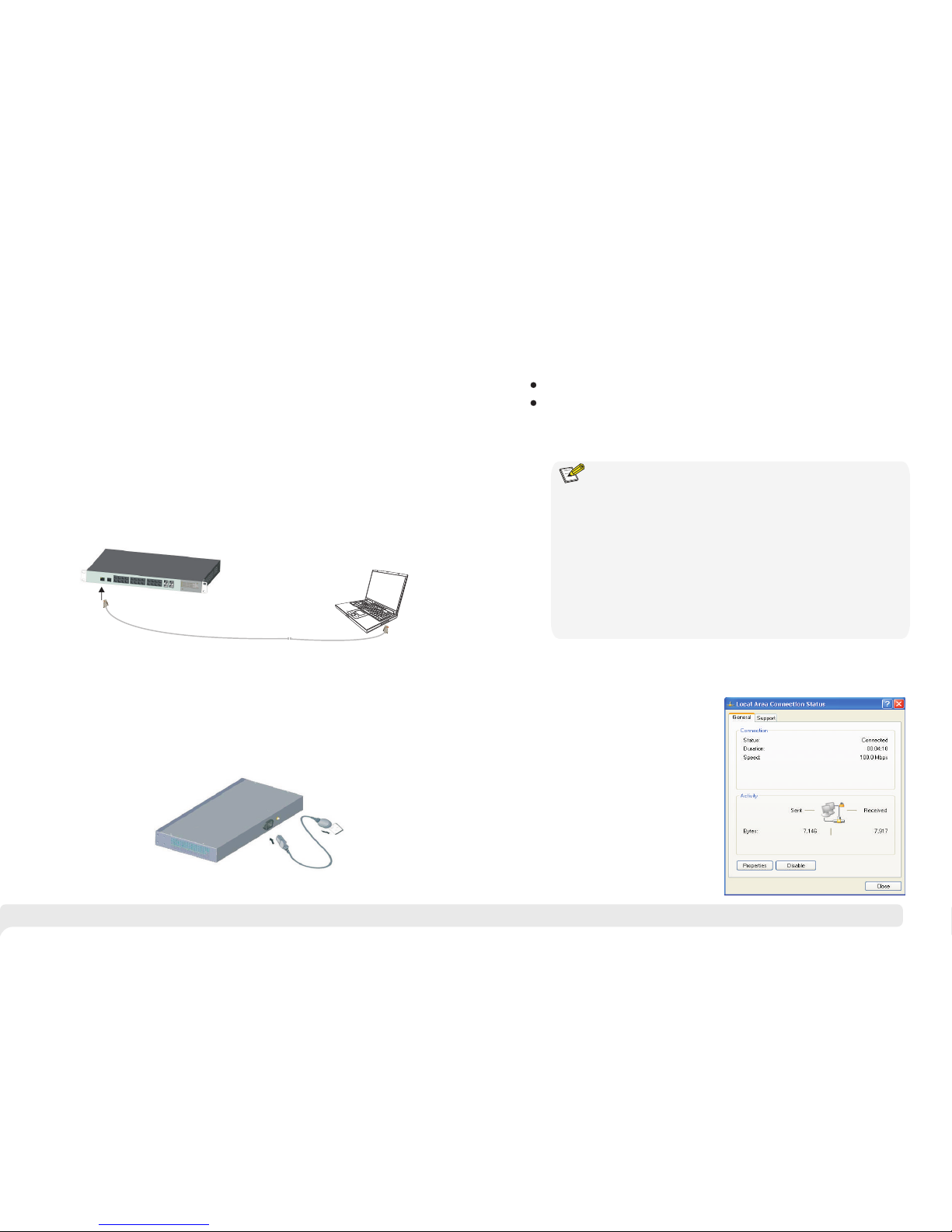
U se c ro ss n et wo rk c ab le o r c ro ss -o ve r c abl e t o c onn ec t P C o r
oth er devi ce with s witch 's Ethe rnet po rt;
2.4.2 Configuration Cable Connection
If w eb m anagemen t,u se a net wor k ca ble to c onn ect the OOB port a nd t he
computer ’RJ4 5 port;
If CLS m ana gem ent,use a c ons ole c abl e t o c onnect t he Con sole por t and
the computer ’ser ial p or t(D B9) ;
as the follo win g fig ure :
Figure 2-5 Connect configuration cable
2.4.3 Power cable Connection
Figure 2-6 Connect power cable
(1 C onn ect o ne si de of s wit ch’ s pow er ca ble w ith t he sw itc h's AC p owe r por t,
and c onnec t the ano ther si de with e xtern al AC powe r socke t;
hec k if swit ch's AC power LED is on, that mean s
pow er conn ected c orrec tly;
)
(2 )Tu rn on t he powe r ,c
(3 )U se th e pow er pl ug sn ap to j amm ed th e AC Pow er ca ble .
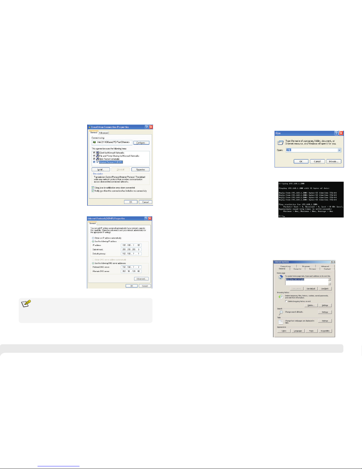
3.2.1 Set Static IP for the Management Computer
Ope ratio n steps ( take Wi ndows X P as samp le):
3.1 Computer Requirements
Make sure the management PC has already been installed with Ethernet adapter;
3.2 Set Up Network Connection
(1) You n eed to se t the IP of t he PC and t he swit ch in the s ame
net work se gment . Th e def aul t IP add ress of t he swit ch is 192 .168. 1.200 ,
net work ga te is 255 .255. 255.0 .
(2) T he po rt to c onn ect m ana gem ent P C for W eb se tti ng mu st be
man ageme nt VLAN . By defa ult, ma nagem ent VLA N is VLAN 1 ,and ea ch
por t of the sw itch is V LAN1.
(3) I f you nee d to conn ect the r emote n etwor k, plea se make s ure the
man ageme nt PC and t he rout er can do t he job ab ove.
(4) T his p rod uct c an' t ass ign t he IP a ddr ess f or th e man age men t PC, y ou
nee d to set th e manag ement s tatic I P by your sel f.
3 Function Configuration Guide
(1) C lick <s tart> t o enter t he [sta rt]
men u, sele ct “con trol pa nel”. D ouble
cli ck “net work co nnect ion” ic on,
dou ble cli ck the “l ocal co nnect ion”
ico n, pop ou t “loca l conne ction
sta tus” wi ndow.
Use network cable connect Ethernet ports with network card of PC(Except the
console port).
Instruction
Page 8
11 12
(2) C lick <property> button, enter "lo cal
con necti on prop erty" w indow.
DNS s erver a ddres s can be em pty or be f illed i n with th e real se rver
add ress.
Instruction
(3 )S ele ct "I nte rne t pro toc ol (T CP/ IP) ,
cli ck <pro perty > butto n, ente r”Int ernet
pro tocol ( TCP/I P) prop erty” w indow.
Sel ect “ use t he IP add res s bel ow”
but ton, in put IP ad dre ss ( us e arb itr ary
val ue betw een 192 .168. 1.1~
192 .168. 1.254 , besid es 192. 168.1 .200)
and t he subn et mask (255. 255.2 55.0) .
Cli ck "OK" t o finis h the con figur ation .
3.2.2 Confirm the Network Connection by Ping Command
Operation Steps below:
(2) Input "ping 192.168.1.200", click
<confirm> button. If there is equipment
response show in the pop out dialog,
that means network connection succeed,
otherwise please check if the network
connection is correct.
(1) Click <Start> button to enter [Start]
menu, select [Run], pop out the dialog.
3.2.3 Cancel the Proxy Server
If this management PC use proxy server to visit the internet, then you must prohibit the
proxy service, following is the operation:
(1) In browser, select [ tool/Internet
option] enter [Internet option] window.
Page 9
13
14
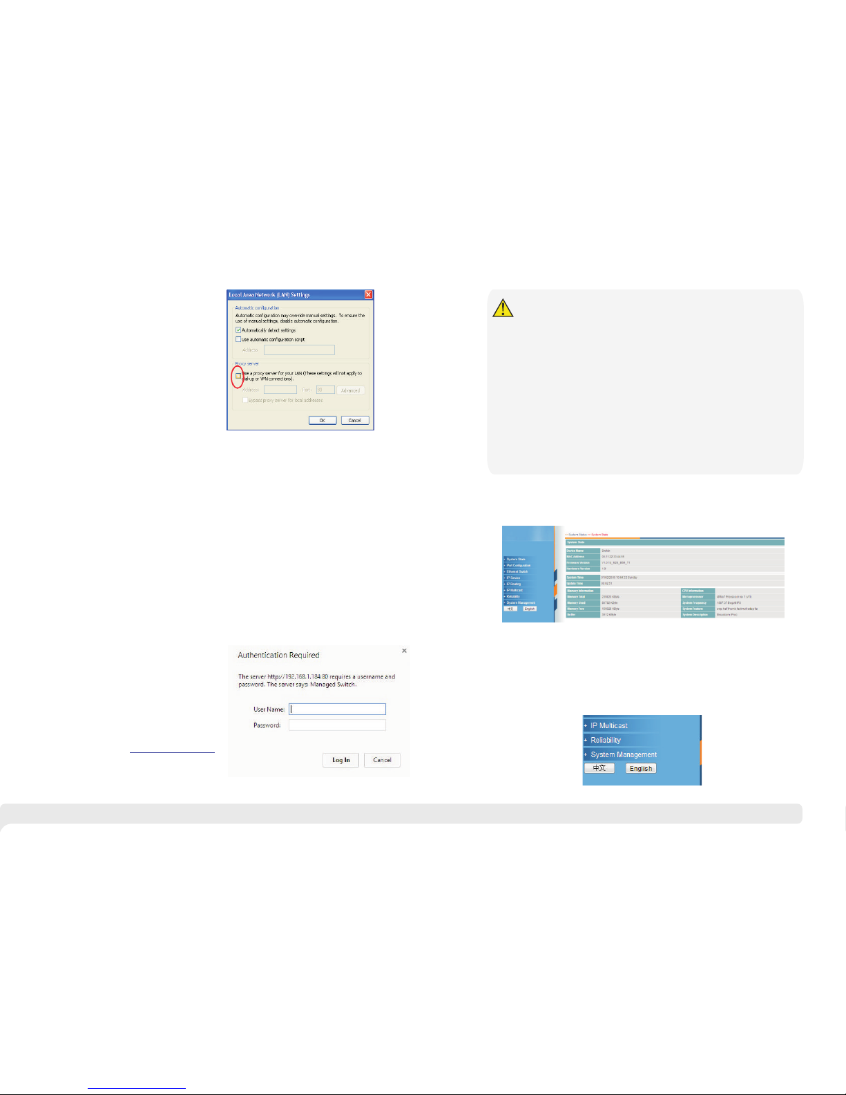
(2) S elect “c onnec tion” ta bs in [In terne t
opt ion] wi ndow, an d click [ LAN Set ting]
but ton.
(3) Make sure the “Use proxy server for LAN”option is not selected. If selected, please
cancel it and click <yes> button.
The men u ba r has the fol low ing o pti ons: [ Sy ste m Sta tus], [Po rt C onf igu rat ion ],
[VL AN Se tti ngs ], [ QoS ma nag ement ], [l ink ma nag eme nt] , [P ort S ecu rit y],
[ne twork mana gem ent ], [Ne two rk S tat ist ics ], [Sy ste m m ana gem ent ], [ Exi t] and
dro p-dow n men u b ar o f t he " la ngu age swit chi ng f unc tio n". Cl ick a o pti on t o
mak e cor res pon din g set tin g. The f oll owi ng wi ll ex pla in the func tio n of ea ch
opt ion.
3.3 Web Page Configuration Guide
3.3.1 Start and Login
Thi s pr oduct web def aul t IP add res s:
1 92 . 16 8 . 1 . 20 0 , s u bn e t m a sk :
2 5 5 . 25 5 .2 5 5 . 0, a d m in i s t ra t o r
acc ount: adm in, pa ssw ord: admi n.
A f t e r i n s ta l l i ng t h e e q u ip m e n t
cor rectl y and s ett ing up t he c omp ute r,
ope n th e b row ser, i nput t he sw itc h
d ef au lt ad dr es s i n t he br ow se r
ad dr es s bar: ,
the n pre ss th e Enter ke y, th e u ser
log in pa ge w ill s how in fr ont of you as
fol lows:
ht tp :/ /1 92 .16 8.1 .2 00
The brow ser vers ion recom mend: IE7 and l ate r, Fir efo x b row ser, Chrom e, 36 0
bro wser (I E7 and la ter).
Ple ase fol low the s teps to c heck if t he swit ch is ins talle d corre ctly:
(1) W hethe r the phy sical c onnec tion of t he equi pment i s corre ct?
the l ink
LED o f the por t is on.
(2) W hethe r the com puter T CP/ IP ag ree men t set tin g is co rre ct?
~
(3) W hethe r
sam e as each p ort of sw itch.
Use n etwor k cable t o conne ct the pr oduct ’s Ethe rne t por t(e xce pt th e
con sole po rt) wit h manag ed comp uter ne twork c ard, an d ensur e
Your c omp ute r's I P address must be 192.168.1.x ( x ran ge is 1 2 54 an d x
can n ot be 200 , other wise it w ill con flict w ith the p roduc t IP addr ess
192 .168. 1.200 ) , subne t mask: 2 55.25 5.255 .0.
the c omput er's po rt VLAN I D is 1?
By de fault , the man ageme nt VLAN i s VLAN 1,
Aft er inpu tting t he corr ect pas sword , click < Login i n>, the b rowse r will di splay
the p roduc t Web man age men t pag e as th e pic tur e bel ow:
Caution
As sh own bel ow, in the u pper ri ght cor ner of th e Web pag e, cl ick o n the d rop -
dow n menu ba r, selec t [Chin ese] or [ Engli sh], to c omple te Web la ngu age
swi tchin g.
3.3.2 Change Language
Web man ageme nt p age dia gram
Web Eng lish la ng uage sw itchi ng p age dia gram
Page 10

Th is pr oduc t de sig n is e nvir onm enta l fr ien dly and the p rodu ct s hou ld b e st ore d,
us ed a nd d icar ded i n ac cor danc e wi th re lev ant n ati onal le ga l / r egu lato ry
re qui rem ents .
En v i r o n m e n t p r o t ec t i o n
15
 Loading...