

Page 1
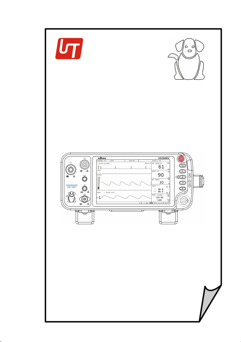
VS2000V
Veterinary Vital Signs Monitor
Operation Manual
-
English
V
ersion
1.0,
March 2011
©
2011 UTECH Co., Ltd.
All
rights reserved.
Page 2

Page 3

Table of Contents
Table of Contents
Warranty and Service Information ......................................... VII
Proprietary Notice ...................................................................... VII
Limited Warranty ....................................................................... VII
Disclaimer of Warranties ........................................................... VIII
Conditions of Warranty .............................................................. VIII
Limitation of Remedies .............................................................. VIII
Service Support ......................................................................... VIII
Chapter 1: Introduction ......................................................... 1-1
1.1 About this Manual ............................................................... 1-1
1.2 Using the Manual ................................................................. 1-1
1.3 Definition of Symbols ........................................................... 1-1
1.4 Warning Information ............................................................ 1-2
Chapter 2: Intended Use and General Information ................. 2-1
2.1 Intended Use ....................................................................... 2-1
2.2 Measurement Capabilities .................................................... 2-1
Chapter 3: Controls and Features .......................................... 3-1
3.1 Indicators and Displays with Embedded Submenus ............... 3-1
3.2 Keys ..................................................................................... 3-3
3.3 Left Panel ............................................................................. 3-4
3.4 Back Panel ........................................................................... 3-5
3.5 Internal Battery.................................................................... 3-6
Chapter 4: Setting up the Monitor ......................................... 4-1
4.1 Unpacking the Monitor and Check the Shipment .................. 4-1
4.2 Quick Setup Instructions ...................................................... 4-1
4.3 Detailed Setup Instructions .................................................. 4-1
4.4 Basic Operation .................................................................... 4-2
4.5 Systems Setup ...................................................................... 4-3
4.5.1 Time Setup .................................................................................... 4-3
4.5.2 Unit Setup ..................................................................................... 4-4
4.5.3 Net Setup ...................................................................................... 4-4
4.5.4 Volume Setup ............................................................................... 4-5
4.5.6 LCD Brightness Setup .................................................................... 4-6
Veterinary Vital Signs Monitor Operation Manual I
Page 4

Table of Contents
4.5.7 Power Setup .................................................................................. 4-7
4.5.8 Language Setup ............................................................................. 4-7
4.6 Set Patient Information ....................................................... 4-8
4.6.1 How to use the keyboard ............................................................. 4-8
4.6.2 Patient Setup................................................................................. 4-9
4.7 Display Setup ..................................................................... 4-10
4.7.1 Customize Display Modes ........................................................... 4-11
Chapter 5: Monitoring the Patient ........................................ 5-1
5.1 General Monitoring Instructions .......................................... 5-1
5.2 Attach the Patient ............................................................... 5-1
5.3 Adjust the Waveforms Settings ............................................ 5-1
5.4 Adjust the Parameter Box Settings ....................................... 5-2
5.5 Set Alarm Limits .................................................................. 5-2
5. 6 Use these Features as Needed............................................. 5-3
5.6.1 Responding to an Alarm ............................................................... 5-3
5.6.2 NIBP Mode .................................................................................... 5-4
5.6.3 Freeze Mode ................................................................................. 5-5
5.6.4 Trends ............................................................................................ 5-5
5.6.5 Viewing Stored Trend Data ........................................................... 5-6
Chapter 6: Alarms ................................................................. 6-1
6.1 Parameter Alarms and Technical Alarms .............................. 6-1
6.2 High, Medium, and Low Priority Alarms ............................... 6-1
6.3 Controlling Alarms ............................................................... 6-2
6.3.1 Change alarm limits ...................................................................... 6-3
6.3.2 Silence alarms ............................................................................... 6-4
Chapter 7: ECG...................................................................... 7-1
7.1 ECG Measurement Capability ............................................... 7-1
7.2 ECG Warnings, Cautions, and Notes ..................................... 7-1
7.3 Theory of Operation ............................................................ 7-1
7.4 Attaching the Patient ........................................................... 7-2
7.5 Choosing the Waveform Settings ......................................... 7-4
7.5.1 Access the ECG Waveform Menu ................................................. 7-4
7.5.2 Change the Primary ECG Lead ...................................................... 7-4
7.5.3 Choose the Waveform Size ........................................................... 7-5
II
Veterinary Vital Signs Monitor Operation Manual
Page 5

Table of Contents
7.5.4 Choose the Waveform Speed ....................................................... 7-6
7.6 Adjusting the Settings in the Parameter Box ......................... 7-6
7.6.1 HR Alarm Setup ............................................................................. 7-6
7.6.2 Choose the Heart Rate Source ..................................................... 7-8
7.7 Monitoring ST ...................................................................... 7-9
7.1.1 Turn on the ST Switch ................................................................... 7-9
7.1.2 ST Display .................................................................................... 7-10
7.1.3 ST Alarm Setup ........................................................................... 7-10
Chapter 8: Oximetry .............................................................. 8-1
8.1 Oximetry Measurement Capability ....................................... 8-1
8.2 Oximetry Warnings, Cautions, and Notes .............................. 8-1
8.3 Pulse Oximetry Theory of Operation ..................................... 8-2
8.4 Attaching the Patient ........................................................... 8-3
8.5 Performance Considerations ................................................ 8-5
8.6 Choosing the Waveform Settings .......................................... 8-6
8.6.1 Access the Waveform Menu ........................................................ 8-6
8.6.2 Fill the Pleth Waveform ................................................................ 8-6
8.6.3 Choose the Waveform Speed ....................................................... 8-7
8.7 Adjusting the Settings in the Parameter Box ......................... 8-8
8.7.1 SpO2 Alarm Setup ......................................................................... 8-8
8.7.2 Choose the Averaging Period for the Oximetry Parameter ........ 8-9
Chapter 9: Non-invasive Blood Pressure ................................ 9-1
9.1 Non-invasive Blood Pressure Measurement Capability .......... 9-1
9.2 Non-invasive Blood Pressure Warnings, Cautions, and Notes 9-1
9.3 NIBP Theory of Operation..................................................... 9-2
9.4 Measurement Limitations .................................................... 9-3
9.5 Attaching the Patient ........................................................... 9-3
9.6 Adjusting the Settings in the Parameter Box ......................... 9-6
9.6.1 NIBP Alarm Setup ......................................................................... 9-6
9.6.2 Choose the Interval for Automatic NIBP Measurements ............ 9-7
9.6.3 Assist Venous Puncture ................................................................ 9-8
9.7 Measuring Non-invasive Blood Pressure (NIBP) ..................... 9-9
9.7.1 Manual NIBP Mode ...................................................................... 9-9
9.7.2 Auto NIBP Mode ........................................................................... 9-9
9.7.3 STAT NIBP Mode ........................................................................... 9-9
Veterinary Vital Signs Monitor Operation Manual III
Page 6

Table of Contents
9.7.4 Canceling the an NIBP Measurement ......................................... 9-10
9.8 Cleaning the NIBP Cuff ........................................................ 9-10
Chapter 10: Respiration Rate (Resp) ..................................... 10-1
10.1 Respiration Rate Measurement Capability ......................... 10-1
10.2 Respiration Rate Warnings, Cautions, and Notes ............... 10-1
10.3 Attaching to the Patient .................................................... 10-1
10.4 Choosing the Waveform Settings ...................................... 10-1
10.4.1 Change the ECG Lead ................................................................ 10-1
10.4.2 Choose the Waveform Size ....................................................... 10-2
10.4.3 Choose the Waveform Speed ................................................... 10-3
10.5 Adjusting the Settings in the Parameter Box ...................... 10-3
10.5.1 RR Alarm Setup ......................................................................... 10-3
Chapter 11: Temperature ..................................................... 11-1
11.1 Temperature Measurement Capability .............................. 11-1
11.2 Temperature Warnings, Cautions, and Notes ..................... 11-1
11.3 Attaching the Patient ........................................................ 11-1
11.4 Adjusting the Settings in the Parameter Box ...................... 11-2
11.4.1 TEMP Alarm Setup .................................................................... 11-2
Chapter 12: Drug Calculator ................................................. 12-1
12.1 Accessing the Drug Calculator ........................................... 12-1
12.2 Measurement Units .......................................................... 12-1
12.3 Glossary ........................................................................... 12-2
12.4 Performing Drug Calculation ............................................. 12-3
12.5 Charting Infusion Progress ................................................ 12-5
12.6 Using the Titration Table ................................................... 12-6
12.7 Recalculation .................................................................... 12-6
Chapter 13: Maintenance and Troubleshooting .................... 13-1
13.1 Cleaning the Monitor's Surfaces ........................................ 13-1
13.2 Long-term Storage ............................................................ 13-2
13.3 Operator's Troubleshooting Chart ..................................... 13-2
13.4 Maintenance Menu .......................................................... 13-4
13.4.1 Access the Maintenance Menu ................................................ 13-4
13.4.2 Back to Factory Default Values................................................. 13-5
13.4.3 Using the Demo Mode .............................................................. 13-5
IV
Veterinary Vital Signs Monitor Operation Manual
Page 7

Table of Contents
Chapter 14: Optional Supplies and Accessories .................... 14-1
14.1 Ordering Information ....................................................... 14-1
Chapter 15: Specification .................................................... 15-1
15.1 Display ............................................................................. 15-1
15.2 Indicators ......................................................................... 15-1
15.3 Alarm Volume .................................................................. 15-1
15.4 Keys/User Controls ........................................................... 15-1
15.4 ECG .................................................................................. 15-2
15.5 SpO2 ................................................................................ 15-2
15.6 NIBP ................................................................................ 15-3
15.7 Respiration Rate (RESP) .................................................... 15-3
15.8 Temperature (TEMP) ........................................................ 15-4
15.9 Default Alarms Limits ....................................................... 15-4
15.10 Power Requirement ....................................................... 15-4
15.11 Dimensions .................................................................... 15-4
15.12 Environmental ................................................................ 15-5
15.13 Equipment Classification ................................................ 15-5
Veterinary Vital Signs Monitor Operation Manual V
Page 8

Table of Contents
This Page is Intentionally Left Blank!
VI
Veterinary Vital Signs Monitor Operation Manual
Page 9

Warranty and Service Information
Warranty and Service Information
Proprietary Notice
Information contained
may not
approval of UTECH
detailed
spare parts for the device
document
publication or revision, but
be
duplicated in full or part by any person without prior written
documentation
is believed to be current and accurate as of the date of
Limited Warranty
Utech Co., Ltd. ("Seller") warrants to the original purchaser that the Product,
not including applicable accessories, shall be free from defects in material and
workmanship under normal use, if used in accordance with its labeling, for
one year
Seller warrants to the original purchaser that the reusable oximeter sensors
supplied as accessories, shall be free from defects in materials and
workmanship under normal use, if used in accordance with its labeling, for
one year from the date of shipment to the original purchaser.
Seller warrants to the original purchaser that the reusable ECG leads and
reusable NIBP purple hose supplied as accessories, shall be free from defects
in materials and workmanship under normal use, if used in accordance with its
labeling, for 90 days from the date of shipment to the original purchaser.
Blood pressure cuffs carry a (6) six month warranty, pending evaluation by
Utech Co., Ltd. (UTECH) Technical Services. Cuffs that are contaminated, have
liquid in them, have been misused/ abused or are older than (6) months will
not be covered under warranty. The sole obligation of UTECH under this
warranty will be to repair or replace, at its option, products that prove to be
defective during the warranty period.
The foregoing shall be the sole warranty remedy. Except as set forth herein,
seller makes no warranties, either expressed or implied, including the implied
warranties of merchantability and fitness for a particular purpose. No
warranty is provided if the products are modified without the express written
from the date of shipment to the original purchaser.
in this
document
Co.,
Ltd. Its purpose is to provide the user with
to efficiently install, operate, maintain and order
supplied. All information
does
not
is
copyrighted
constitute
a warranty.
by Utech
contained
Co., Ltd. and
adequately
in
this
Veterinary Vital Signs Monitor Operation Manual
VII
Page 10

Warranty and Service Information
consent of Utech Co., Ltd. and seller shall not be liable in any event for
incidental or consequential damage. This warranty is not assignable.
Warranties are subject to change. Please contact Utech Co., Ltd. for current
warranty information.
Disclaimer of Warranties
THE FOREGOING EXPRESS WARRANTY, AS CONDITIONED AND LIMITED, IS IN
LIEU OF AND EXCLUDES ALL OTHER WARRANTIES WHETHER EXPRESS OR
IMPLIED, BY OPERATION OF LAW OR OTHERWISE, INCLUDING BUT NOT
LIMITED TO, ANY IMPLIED WARRANTIES OF MERCHANTABILITY OR FITNESS
FOR A PARTICULAR PURPOSE.
Seller disclaims responsibility for the suitability of the Product for any
particular medical treatment or for any medical complications resulting from
the use of the Product. This disclaimer is dictated by the many elements which
are beyond Seller's control, such as diagnosis or patient, conditions under
which the Product may be used, handling of the Product after it leaves Seller's
possession, execution of recommended instructions for use and others.
Conditions of Warranty
This warranty is void of the Product has been altered, misused, damaged by
neglect or accident, not properly maintained or recharged, or repaired by
persons not authorized by Seller. Misuse includes, but is not limited to, use
not in compliance with the labeling or use with accessories not manufactured
by Seller. This warranty does not cover normal wear and tear and
maintenance items.
Limitation of Remedies
The original purchaser's exclusive remedy shall be, at Seller's sole option, the
repair or replacement of the Product.
event will Seller's liability arising out of any cause whatsoever (whether such
cause is based in contract, negligence, strict liability, tort or otherwise)
exceed the price of the Product and in no event shall Seller be responsible
for consequential, incidental, or special damages of any kind or nature
whatsoever, including by not limited to, lost business, revenues and profits.
THIS IS THE EXCLUSIVE REMEDY. In no
Service Support
VIII Veterinary Vital Signs Monitor Operation Manual
Page 11

Warranty and Service Information
Web site
www.
chinautech.com
Repairs for devices manufactured by UTECH company under warranty must be
made at authorized repair centers. If the device needs repair, contact your
local distributor or the UTECH company after-service department. When
calling, have the device’s model and serial number ready.
If you need to ship the device, pack the device and accessories carefully to
prevent shipping damage. All accessories should accompany the device.
3rd floor, NO.39, Jinqiao Road,
Zhangjiawan, Shapingba District,
Chongqing, China
NOTE!
Shipments received without a return number will be returned to
sender.
Phone
Fax
E-mail
(+86)23-6172-8390
(+86)23-6172-8391
[email protected]
Keep all original packing material, including any inserts. If you need to ship the
device, use only the original packaging material, including inserts. Box and
inserts should be in original condition. If original shipping material in good
condition is not available, it should be purchased from Utech Co., Ltd.
Damages occurring in transit in other than original shipping containers are the
responsibility of the shipper. All costs incurred returning devices for repair are
the responsibility of the shipper.
Veterinary Vital Signs Monitor Operation Manual
IX
Page 12

Warranty and Service Information
This Page is Intentionally Left Blank!
X Veterinary Vital Signs Monitor Operation Manual
Page 13

Chapter 1: Introduction
Attention, see in instructions for use
NIBP Start/ Stop
Key
Alarm S
ilence
Battery Supply
LED
Chapter 1: Introduction
1.1 About this Manual
The Operation Manual provides installation, operation, and
instructions for health-care professionals and other
monitoring respiratory and cardiovascular activity.
users, trained in
maintenance
These instructions contain important information for the safe use of the
product. Read the entire contents of these Instructions For Use, including
Warnings and Cautions, before using the monitor. Failure to properly follow
warnings, cautions and instructions could result in death or serious injury to
the patient.
1.2 Using the Manual
The monitor allows you to choose the measurement capabilities you need. A
measured value refers to a derived or calculated value; a parameter refers to
one or more specific measured values. For example, pulse rate and %SpO2 are
measurements; the oximeter parameter consists of both these measured
values. Operation of the monitor is the same regardless of the number of
parameters you use.
If you are not familiar with the operation of this monitor, follow each chapter
in the manual in order. Each chapter builds on the information from the
previous chapter. If the monitor is already set up, or if you are familiar with its
operation, turn to the chapter that describes the features you will use.
1.3 Definition of Symbols
SYMBOLS
DEFINITION
Type BF Defibrillation
Defibrillator-proof type CF equipment
Freeze Key
Veterinary Vital Signs Monitor Operation Manual 1-1
Page 14
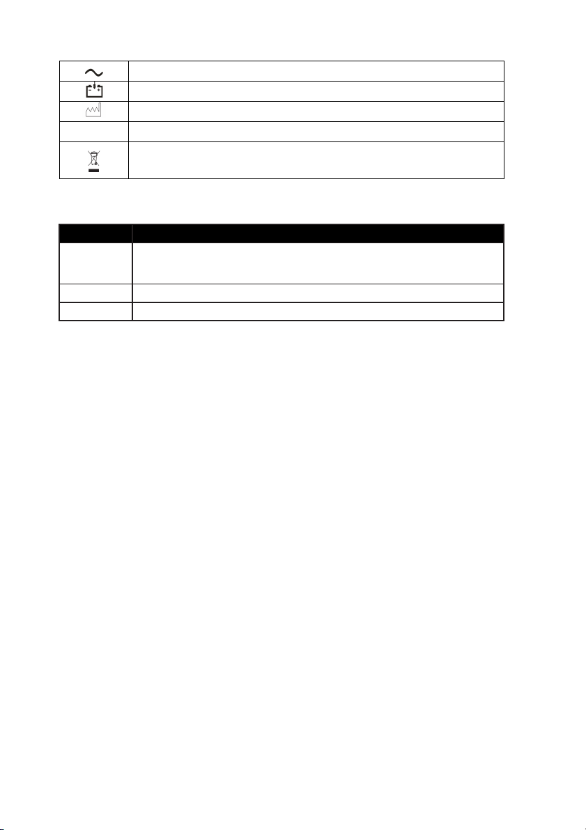
Chapter 1: Introduction
AC Power LED
Battery Charge LED
Date of Manufacturing
Drip Proof (monitor only)
equipment.
CAUTION
Tells you something that could damage the device.
IPX1
Indicates separate collection for electrical and electronic
1.4 Warning Information
KEYWORD
WARNING Tells you something that could hurt the patient or hurt the
operator.
NOTE Tells you other important information.
DEFINITION
General Warning, Cautions, and Notes
WARNING! Do not use this device in the
anesthetics
with air, oxygen-enriched environments, or nitrous oxide.
or other flammable substance in combination
WARNING! ELECTRICAL SHOCK HAZARD when cover is removed. Do not
remove covers. Refer servicing to qualified personnel.
WARNING! Do not use this device in the presence of magnetic resonance
imaging (MR or MRI) equipment.
WARNING! Do not plug the monitor into an outlet controlled by a wall
switch.
WARNING! This device is intended for use by persons trained in
professional health care. The operator must be thoroughly
familiar with the information in this manual before using the
device.
WARNING! Do not autoclave, ethylene oxide sterilize, or immerse the
monitor and other accessories in liquid. Evidence that liquid
has been allowed to enter the monitor voids the warranty.
WARNING! This device must be used in conjunction with clinical signs and
symptoms. This device is only intended to be an adjunct in
1-2 Veterinary Vital Signs Monitor Operation Manual
presence
of flammable
Page 15

Chapter 1: Introduction
patient assessment.
WARNING! Equipment is protected against defibrillator discharge. Rate
meters and displays may be temporarily affected during
defibrillation, but will rapidly recover.
WARNING! The vital sings monitor is suitable for use within the patient
environment IEC 60950 approved equipment must be placed
outside of the patient environment. The patient environment
is defined as any volume in which intentional or unintentional
contact can occur between the patient and parte of systems or
between the patient and other persons touching parts of the
system.
WARNING! When connecting this monitor to any instrument, verify proper
operation before clinical use. Use only equipment meeting
specifications given in this manual. Refer to the instrument's
user manual for full instructions. Accessory equipment
connected to the monitor's data interface must be certified
according to the respective IED standards, i.e. IEC 60950 for
data processing equipment or IEC 60601-1 for electro medical
equipment. All combinations of equipment must be in
compliance with IEC 60601-1-1 systems requirements. Anyone
connecting additional equipment to the signal input port or
signal output port configures a medical system, and therefore,
is responsible that the system complies with the requirements
of the system standard IEC 60601-1-1.
WARNING! Any monitor that has been dropped or damaged should be
checked by qualified service personnel to ensure proper
operation prior to use.
WARNING! Use only original manufacturer or recommended patient cables.
Use of accessories other than those specified may result in
increased electro-magnetic (EM) emissions or decreased EM
immunity of the device. To avoid potential electro-static
discharge interference, do not use cables that incorporate
metal or metal-coated connectors.
WARNING! Medical electrical equipment, including this device, needs
special precautions regarding electro-magnetic compatibility
(EMC) and needs to be installed and put into service according
Veterinary Vital Signs Monitor Operation Manual 1-3
Page 16

Chapter 1: Introduction
to the EMC information provided in this manual.
WARNING! There is no defibrillator synchronization output on the monitor.
Make no connections between the monitor and a defibrillator.
WARNING! This monitor will not operate effectively on patients who are
experiencing convulsions or tremors.
WARNING! This monitor is not for home use.
WARNING! The monitor should not be used adjacent to or stacked with
other equipment. If adjacent or stacked use is necessary, the
monitor should be observed to verify normal operation in the
configuration in which it will be used.
WARNING! This monitor is not for apnea detection. The monitor has not
been tested or validated for use in apnea detection.
WARNING! Verify proper operating mode before attaching patient. See
Select the Patient Type in Chapter of Setting Up the Monitor.
WARNING! Default alarm limits are provided for convenience. Verify that
alarm limits are appropriate for given patient and condition,
and adjust according to institutional policy.
WARNING! Ensure the monitor's AC rating is correct for the AC voltage at
your installation site before using the monitor. The monitor's
AC rating is shown on the rear panel rating plate. If the rating is
not correct, do not use the monitor.
WARNING! Disconnect the AC power supply from the outlet before
disconnecting it from the monitor. Leaving the AC power
supply connected to an AC power outlet without being
connected to the monitor may result in a safety hazard.
WARNING! Do not allow any moisture to touch the AC power supply
connectors or a safety hazard may result. Ensure that hands
are thoroughly dry before handling the AC power supply.
WARNING! Do not place the monitor in the patient's bed. Do not place the
monitor on the floor.
1-4 Veterinary Vital Signs Monitor Operation Manual
Page 17

Chapter 1: Introduction
WARNING! Failure to place the monitor away from the patient may allow
the patient to turn off, reset, or damage the monitor, possibly
resulting in the patient not being monitored. Make sure the
patient cannot reach the monitor from their bed.
WARNING! If there is a risk of the AC power supply becoming disconnected
from the monitor during use, secure the cord to the monitor
several inches from the connection.
WARNING! This device is intended for use by trained healthcare
professionals. The operator must be thoroughly familiar with
the information in this manual before using the device.
WARNING! Do not disassemble the unit. The unit is not use serviceable.
Refer to qualified service personnel.
WARNING! It is the operator's responsibility to set alarm limits
appropriately for each individual patient.
WARNING! If the accuracy of any measurement is in question, check the
patient's vital sign(s) by an alternative method and then check
the monitor for proper functioning.
WARNING! Operation of this device may be affected in the presence of
strong portable and mobile communications equipment.
WARNING! Operation of this device may be adversely affected in the
presence of computed tomography (CT) equipment.
CAUTION! Do not allow water or any other liquid to be spilled onto the
monitor. Unplug the AC power cord from the monitor before
cleaning or disinfecting the monitor.
CAUTION! This unit contains a lithium coin battery and a rechargeable
alkaline battery. These batteries are not user replaceable.
Refer servicing to qualified personnel.
CAUTION! Pressing front panel keys with sharp or pointed instruments
may permanently damage the keypad. Press the front panel
keys only with your finger.
CAUTION! Blocking the ventilation holes on the monitor's rear panel can
Veterinary Vital Signs Monitor Operation Manual 1-5
Page 18

Chapter 1: Introduction
prevent air circulation inside the monitor, possibly resulting in
damage to the monitor. Leave an air gap behind the monitor to
allow air to circulate through the ventilation holes.
CAUTION! Chemicals used in some cleaning agents may cause brittleness
of plastic parts. Follow cleaning instructions in this manual.
CAUTION! If the device becomes wet, wipe off all moisture and allow
sufficient time for drying before operating.
CAUTION! Follow local governing ordinances and recycling instructions
regarding disposal and recycling of device components and
packaging.
NOTE! All user and patient accessible materials are non-toxic.
NOTE! Each input and output connection of the monitor is electrically
isolated. Connection of this monitor to other equipment will not
increase leakage current.
ECG Warnings, Cautions, and Notes
WARNING! Connect only three-lead or five-lead ECG lead wires from the
patient to the ECG patient cable. Do not connect any other
signal source to the ECG patient cable.
WARNING! This monitor does not identify or interpret arrhythmia events.
The indication of heart rate may be adversely affected by the
presence of cardiac arrhythmias.
WARNING! Line isolation monitor transients may resemble actual cardiac
waveforms and thus inhibit heart rate alarms.
CAUTION! Only five-lead ECG cable can be used to this monitor. Using the
incorrect cable for the selected mode might lead to a floating
reference or additional noise on the ECG signal.
NOTE! Follow institutional standards when applying ECG electrodes.
Silver/Silver Chloride disposable electrodes are strongly
recommended to avoid polarization effects that result in large
input offset potentials. Use of "squeeze bulb" type electrodes is
not recommended.
1-6 Veterinary Vital Signs Monitor Operation Manual
Page 19

Chapter 1: Introduction
NOTE! Use only standard five-lead ECG cable.
Oximetry Warnings, Cautions, and Notes
WARNING! Prolonged use or the patient's condition may require changing
the sensor site periodically. Change the sensor site and check
skin integrity, circulatory status, and correct alignment at least
every 4 hours.
WARNING! When attaching sensors with micro foam tape, do not stretch
the tape or attach the tape too tightly. Tape applied too tightly
may cause inaccurate readings and blisters on the patient's
skin (lack of skin respiration, not heat, causes the blisters).
WARNING! Using a damaged sensor may cause inaccurate readings,
possibly resulting in patient injury or death. Inspect each
sensor. If a sensor appears damaged, do not use it. Use another
sensor or contact your authorized repair center for help.
WARNING! Using a damaged patient cable may cause inaccurate readings,
possibly resulting in patient injury or death. Inspect the patient
cable. If the patient cable appears damaged, do not use it.
Contact your authorized repair center for help.
WARNING! Failure to carefully route the cable from the sensor to the
monitor may allow the patient to become entangled in the
cable, possibly resulting in patient strangulation. Route the
cable in a way that will prevent the patient from becoming
entangled in the cable. If necessary, use tape to secure the
cable.
WARNING! If any of the integrity checks fail, do not attempt to monitor
the patient. Use another sensor or patient cable, or contact the
equipment dealer for help if necessary.
WARNING! Do not autoclave, ethylene oxide sterilize, or immerse the
sensors in liquid. Evidence that liquid has been allowed to
enter the monitor voids the warranty.
WARNING! Use only SpO
for use with, this device.
Veterinary Vital Signs Monitor Operation Manual 1-7
sensors supplied with, or specifically intended
2
Page 20

Chapter 1: Introduction
WARNING! SpO2 measurements may be adversely affected in the presence
of high ambient light. Shield the sensor area (with a surgical
towel, for example) if necessary.
WARNING! Dyes introduced into the bloodstream, such as methylene blue,
indocyanine green, indigo carmine, patent blue V (PBV), and
fluorescein may adversely affect the accuracy of the SpO2
reading.
WARNING! Any condition that restricts blood flow, such as use of a blood
pressure cuff or extremes in systemic vascular resistance, may
cause an inability to determine accurate SpO2 and pulse rate
readings.
WARNING! Under certain clinical conditions, pulse oximeters may display
dashes if unable to display SpO2 and/or pulse rate values.
Under these conditions, pulse oximeters may also display
erroneous values. These conditions include, but are not limited
to: patient motion, low perfusion, cardiac arrhythmias, high or
low pulse rates or a combination of the above conditions.
Failure of the clinician to recognize the effects of these
conditions on pulse oximeter readings may result in patient
injury.
CAUTION! Unplug the sensor from the monitor before cleaning or
disinfecting.
NOTE! Obstructions or dirt on the sensor's red light or detector may cause
a sensor failure. Make sure there are no obstructions and the
sensor is clean.
Non-invasive Blood Pressure Warnings, Cautions, and Notes
WARNING! Blood pressure measurements may be inaccurate if cuffs
and/or hoses other than those specified by Utech Co., Ltd. are
used.
WARNING! Repeated use of STAT mode for periods longer than 15 minutes
should be avoided to reduce the patient's risk for soft tissue or
nerve damage. When using the monitor for long periods of
time, select the longest clinically appropriate measurement
1-8 Veterinary Vital Signs Monitor Operation Manual
Page 21

Chapter 1: Introduction
interval and periodically examine the patient for signs of injury
and ensure proper cuff placement.
WARNING! Make sure that hoses are not kinked, compressed, or
restricted.
WARNING! Check that operation of the equipment does not impair the
circulation of the monitored patient.
WARNING! Blood pressure measurements may not be accurate for
patients experiencing arrhythmias.
WARNING! Do not verify the Non-Invasive Blood Pressure calibration while
the cuff is attached to a patient.
WARNING! Verify cuff size is correct for the selected patient mode on the
monitor.
CAUTION! To ensure that the unit remains in calibration, perform a
calibration verification on a yearly basis.
CAUTION! Extremity and cuff motion should be minimized during blood
pressure determinations.
CAUTION! Proper blood pressure cuff size and placement are essential to
the accuracy of the blood pressure determination.
CAUTION! Any blood pressure recording can be affected by the position of
the patient, his or her physiologic condition, and other factors.
CAUTION! Blood pressure measurements should be interpreted by a
doctor.
NOTE! There are no user-serviceable adjustments for the Non-Invasive
Blood Pressure calibration verification. If the monitor appears to be
out of calibration, contact your authorized repair center for help.
NOTE! Systolic and diastolic blood pressure measurements determined
with this device are equivalent to those obtained by the trained
observer using the cuff/stethoscope auscultation method.
NOTE! Mean arterial blood pressure measurements determined with this
Veterinary Vital Signs Monitor Operation Manual 1-9
Page 22

Chapter 1: Introduction
device are equivalent to those obtained by an intra-arterial blood
pressure measurement device as determined by Utech Co., Ltd.
Respiration Rate Warnings, Cautions, and Notes
WARNING! Respiration monitoring is not recommended on active patients.
It may lead to false alarm.
WARNING! Install white and red electrodes in opposite positions to obtain
optimum respiration waveform. Avoid placing the cable above
liver and ventricle to reduce false readings produced by the
heart coverage or pulsation blood flow. This is very important
for neonates.
Temperature Warnings, Cautions, and Notes
WARNING! Before monitoring starts, check if the sensor cable is properly
connected. Pull the temperature sensor cable from the channel
1 jack, an error message “T1 sensor is off” is displayed on the
screen and the alarm sound can be heard. The same happens
with the other channel.
WARNING! Be cautious when handling temperature sensors and cables.
When it is not in use, the sensor and cable ought to be in a
loose loop. Tightly folded cable can cause mechanical damage.
WARNING! Temperature calibration should be done once a year (or
according to the schedule specified in the hospital procedure).
If calibration is needed, contact the manufacturer.
WARNING! Disposable temperature sensors should only be used once.
WARNING! During monitoring process, the temperature measurement
instrument will conduct a self-check every hour lasting for two
seconds. This will not affect normal operation of the monitor.
NOTE! Use only temperature sensors and interface cables specifically
intended for use with this device.
1-10 Veterinary Vital Signs Monitor Operation Manual
Page 23

Chapter 2: Intended Use and General Information
Chapter 2: Intended Use and General Information
2.1 Intended Use
This vital signs monitor is intended to be used in special procedure labs and
other areas of a veterinary hospital or clinic where veterinary monitoring
systems are needed. The monitor package includes 5-lead electrocardiography
(ECG), non-invasive blood pressure (NIBP), pulse oximetry (SpO2), Respiration
Rate (RR) and temperature (TEMP).
The device permits patient monitoring with adjustable alarm limits as well as
visible and audible alarm signals. The monitor provides fast, reliable
measurement for patients ranging from cats to horses.
WARNING! The monitor was not
monitor.
WARNING! This monitor is not for home use.
2.2 Measurement Capabilities
Heart/Pulse Rate
Heart/pulse rate is measured with the ECG, oximetry, and non-invasive blood
pressure (NIBP) parameters. The measured values can be continuously
displayed in the ECG and SpO2 parameter boxes. Heart/pulse rate can also be
displayed in the NIBP HISTORY, found in the TRENDS menu. You can choose
the source (AUTO, ECG, or SpO2) of the heart/pulse rate displayed in the ECG
parameter box. If you choose AUTO, the monitor will determine the best
source depending on the quality of available data and selected source priority.
See Choose the Heart Rate Source in the Chapter of ECG for detailed
information regarding the source of the heart/pulse rate displayed in the ECG
parameter box.
Electrocardiography (ECG)
The monitor provides continuous five-lead ECG processing, with standard lead
selections, and filtering from electrocautery discharge. The ECG measured
value (HR) and primary lead selection are displayed in the ECG parameter box,
and an ECG waveform is continuously displayed.
VS2000 Vital Signs Monitor Operation Manual 2-1
designed
or
tested
to be an apnea
Page 24

Chapter 2: Intended Use and General Information
Oximetry
The oximetry parameter provides the continuous non-invasive monitoring of
oxygen saturation (%SpO2) in the blood and pulse rate (PR). The measured
values for oximetry (%SpO2 and PR) and a pulse strength bar graph are
displayed in the SpO2 parameter box. A plethysmogram, or oxygen saturation
waveform, can be continuously displayed. A variety of disposable and reusable
sensors is available for monitoring patients.
Non-invasive Blood Pressure (NIBP)
The non-invasive blood pressure (NIBP) parameter provides systolic, diastolic,
and mean arterial blood pressure values, and heart rate. The measured values
for non-invasive blood pressure (SYS, DIA, and MAP) are displayed in the NIBP
parameter box. NIBP measurements can be made in automatic, manual, or
STAT modes.
Respiration Rate (RR)
The monitor provides respiration rate and Resp waveform by measuring the
thoracic impedance between two ECG electrodes on the patient’s chest. The
measured RR is displayed in the RR parameter box. And the RR waveform is
displayed on the RR waveform Channel.
Temperature (TEMP)
Two independent channels of temperature (T1 and T2) monitoring are
available. Each channel is compatible with Utech Co., Ltd. YSI 400-series
disposable temperature sensors, or equivalent. The measured value for each
temperature channel (T1 and T2) is displayed in the TEMP parameter box.
2-2 VS2000 Vital Signs Monitor Operation Manual
Page 25
Chapter 3: Controls and Features
•
The NIBP mode will be reset to
MANUAL.
Information
Bar
settings, such as alarm limits and
patient information
, and
Chapter 3: Controls and Features
3.1 Indicators and Displays with Embedded Submenus
The monitor has a high-resolution, high-contrast, color LCD display. It provides
a continuous, real-time display of up to four waveforms. It also shows
measured values, chronological data, measurement trends, alarm limits and
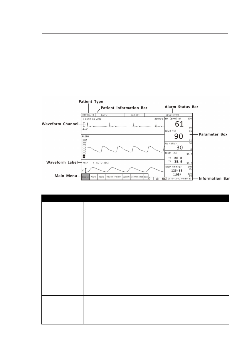
patient information.
DISPLAYS DESCRIPTION
Patient Type
Patient
Alarm Status
Main Menu The main menu provides a means of changing monitor
Veterinary Vital Signs Monitor Operation Manual 3-1
Figure 3.1: Display
You must select the patient type (HORSE, DOG, or CAT)
before monitoring a patient. When you change the
patient type:
•The alarm limits will be reset to their default settings.(if
not in STATIC LIMITS mode)
•NIBP inflation pressure settings will be reset for a cat,
dog, or horse patient.
Patient name and bed number will be shown here.
Shows active alarm events.
Page 26
Chapter 3: Controls and Features
main menu, parameter menus, and
waveform menus.
primary lead and the size of the ECG tracing.
Label
Bar
etc.
percent (%)
.
unavailable.
performing monitoring functions. There are several points
of entry into the monitor's menu system including the
Waveform
Channel
Waveform
Information
Parameter
Box
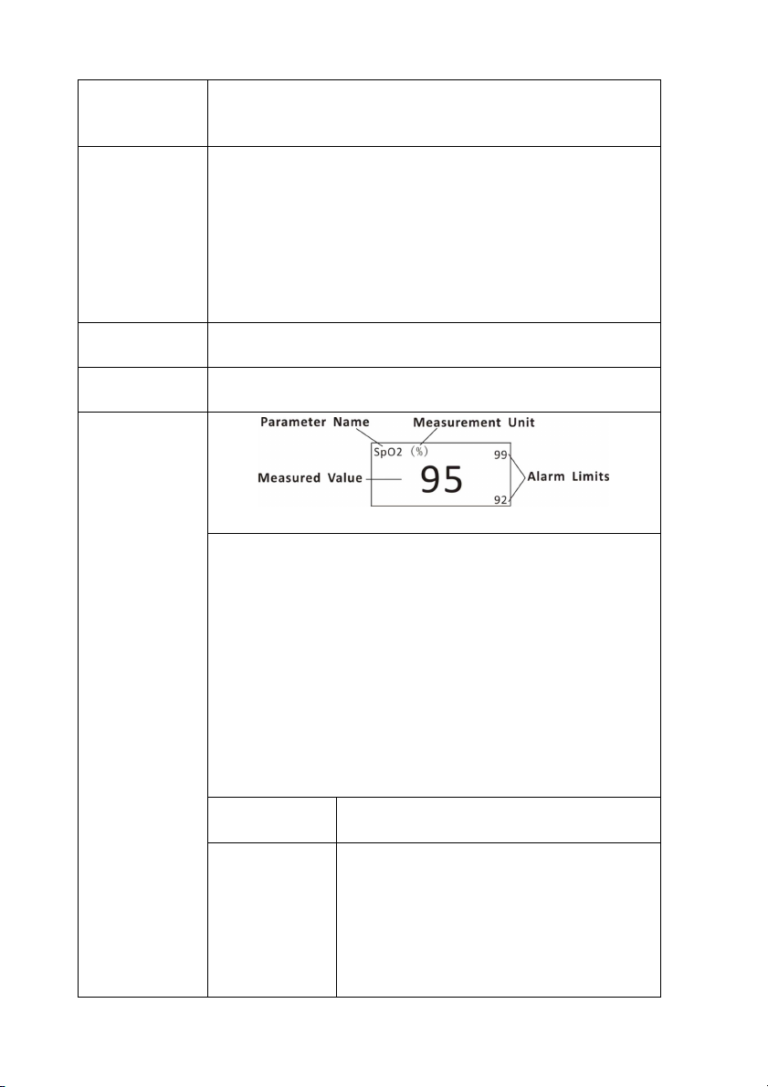
Up to three waveform channels can be displayed
simultaneously. Every channel can be assigned to a
waveform from any enabled parameter, graph, table or
blank. The waveform label provides access to a menu for
each waveform where you can adjust various settings
related to the waveform. For some parameters, such as
ECG, the waveform label displays information about the
The waveform label shows the name of the waveform.
Shows date and time, battery symbol and volume icon
Figure 3.2 Parameter Box
The parameter box provides access to a menu for the
parameter where you can adjust various settings related
to the parameter.
The parameter box contains the parameter or
measurement name, the numeric values for the selected
measurement, the high and low alarm limits, and the
measurement unit. In figure 3.2, the parameter is SpO2,
the numeric measured value is the pulse oxygen
saturation (SpO2), the alarm limits shown are for the pulse
oxygen saturation (SpO2), and the measurement unit is
Parameter
Name
Numeric
Measured
Values
3-2 Veterinary Vital Signs Monitor Operation Manual
The name of the monitored parameter is
displayed.
The number value for the selected
measurement (such as HR or SpO2) is
displayed. The value may be derived or
calculated. Dashes (- - -) in place of a
numeric measured value indicate that
the measurement is invalid or
Page 27
High and Low
will be used.
off
the monitor.
progress, press the key again.
3 Freeze
Silence
mode and the huge digit mode.
6 Menu Key
alarm limits
Chapter 3: Controls and Features
The high and low alarm limits for the
numeric measured values are displayed.
If you do not set alarm limits for a new
patient, the default high and low limits
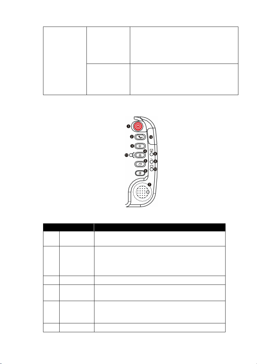
3.2 Keys
No. DESRIPTION
1 ON/OFF
Measurement
Unit
Units of measurement can be changed
for pressure. Pressure measurement
units may be displayed as millimeters of
mercury (mmHg) or kilopascals (kPa).
Figure 3.3: Keys
INSTRUCTION
Hold on this key for 3 seconds to turn on or turn
2 NIBP
4 Alarm
5 Mode Key
Veterinary Vital Signs Monitor Operation Manual 3-3
Press this key to activate an immediate
non-invasive blood pressure (NIBP)
measurement. To cancel an NIBP measurement in
Press this key to freeze the displayed waveform.
Press it in turn to silence the alarm volume for 30
sec, 60sec, 90sec, 120 sec or indefinitely.
Use this key to switch between the four main
display modes: 1 ECG mode, 3 ECG mode, oxyCRG
Press it to enter or exit the main menu.
Page 28
Chapter 3: Controls and Features
Push the knob to select highlighted options.
Supply LED
Power LED
LED
LED
Status LED
to the patient.
Temp
erature
7 Rotary
Knob
The rotary knob is a dial control with a push
selection switch. It is located on the front of the
monitor, in the lower right corner. Turn the rotary
knob to navigate the cursor around the display.
8 Battery
The green Battery Supply LED will light to indicate
that the monitor is supplied by battery.
9 AC
The green AC Power LED will light to indicate that
the monitor is connected to an AC power source.
10
11
Battery
Charge
Alarm
Silence
The green Battery Charge LED will light to indicate
that the monitor is been charging.
The red Alarm Silence LED will flash to indicate
that the alarm volume has been silence for 30
sec, 60sec, 90sec, 120 sec or indefinitely.
12
Work
Green when the monitor is working normal. Red
when there is an alarm.
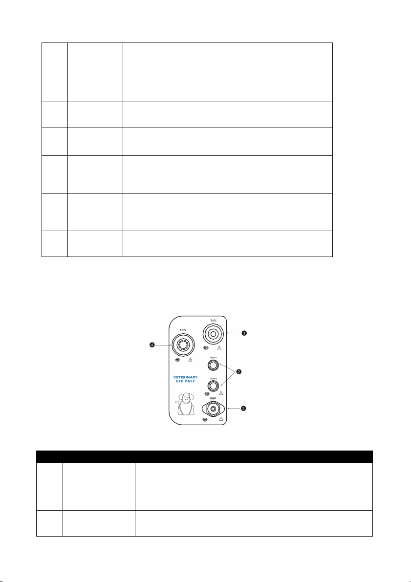
3.3 Left Panel
The left side panel of your monitor contains all of the patient connector
receptacles.
Figure 3.4: Left Panel
NO. DESRIPTION INSTRUCTION
1 Oximetry
Connector
(SpO
)
2
2 Dual
Attach the SpO2 sensor to the monitor. Measured values
for oxygen saturation (%SpO2) in the blood and pulse
rate (PR) will be displayed when the sensor is attached
If the temperature is installed on your monitor, the
TEMP parameter box will appear on the display when
3-4 Veterinary Vital Signs Monitor Operation Manual
Page 29
Connector (T1
displayed when the
sensor is attached to the patient
.
ECG leads are attached to the patient.
1
2
outlet controlled by a wall switch.
4
Interface
6
up and T2 low)
Chapter 3: Controls and Features
the patient connector is attached to the monitor. A
measured value for temperature (TEMP) will be
Non-Invasive
3
Blood Pressure
Connector
(NIBP)
ECG Connector Attach the ECG leads to the monitor. A measured value
4
Attach the NIBP cuff to the monitor. Measured values for
non-invasive blood pressure (systolic, diastolic, and
mean) will be displayed when the most recent NIBP
measurement is complete.
for the ECG heart rate (HR) will be displayed when the
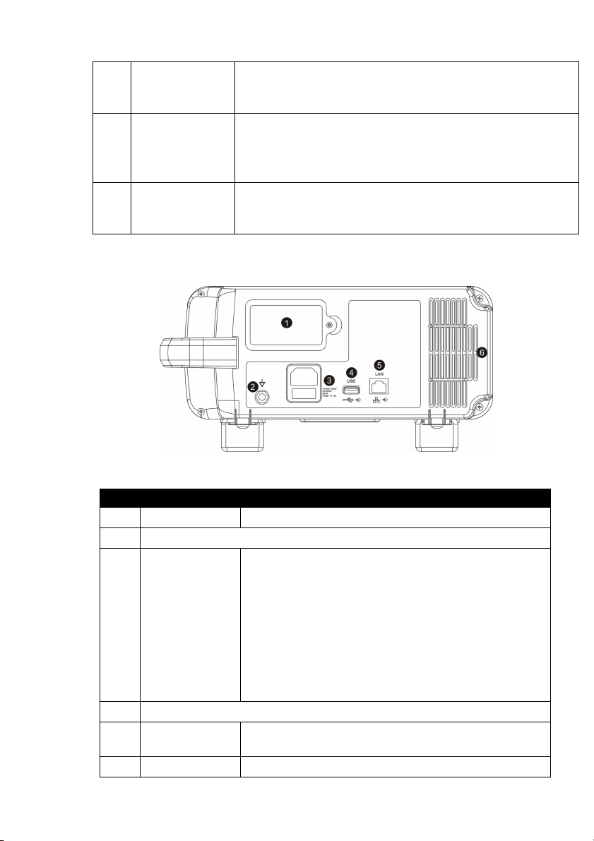
3.4 Back Panel
Figure 3.5: Back Panel
NO. DESRIPTION INSTRUCTION
Battery The monitor is equipped with a lithium battery.
Equipotential Grounding
3
AC Power
Connector
Plug the AC power cord into the AC power
receptacle at the back of the monitor. When the
other end is plugged into a ground, three wire
hospital-grade outlet, the AC Power LED will light.
The monitor automatically switches between 100V
and 240V AC line voltage sources.
WARNING! Do not plug the monitor into an
USB Connector
Network
5
Air Vents The monitor has air vents at the top of the back
Veterinary Vital Signs Monitor Operation Manual 3-5
Connect to the central monitor.
Page 30

Chapter 3: Controls and Features
panel and on the bottom of the monitor.
3.5 Internal Battery
The installed internal rechargeable battery is intended primarily for backup
and switch-over use. Charge the battery after the monitor has operated using
battery power or after the monitor has been shipped or stored. To charge the
battery, connect the AC power cord to the monitor and to the AC power
source. There are no set up requirements for using a charged battery; the
monitor operates exactly the same way under AC or battery power.
To replace the installed rechargeable battery:
1. Disconnect AC power and verify that the monitor is off.
2. Remove the battery door from the bottom of the monitor.
3. Disconnect the battery from the battery cable and remove it from the
battery compartment.
4. Connect a new battery to the battery cable.
5. Insert the battery and cables into the battery compartment.
6. Reattach the battery door to the bottom of the monitor.
7. Connect the AC power cord to the monitor and to the AC power source and
allow the battery to charge fully.
8. Dispose of the battery properly. See the CAUTION below.
CAUTION! The internal rechargeable battery is user-replaceable. It may
contain a Lithium Ion (Li-ion), Nickel Metal Hydride (NiMH), or
Sealed Lead Acid (SLA) battery. Disposal of such batteries
should be conducted in accordance to local and federal
guidelines.
NOTE! Typical battery life is 2 to 5 years depending on usage.
NOTE! When the monitor is connected to AC power, the internal battery
charges whether the monitor is on or off. The Battery Charge LED
flashes while the battery is charging; it is steady when the
3-6 Veterinary Vital Signs Monitor Operation Manual
Page 31

Chapter 3: Controls and Features
battery is fully charged. Allow the battery to fully recharge
before using the monitor under battery power.
NOTE! When approximately 15 minutes of battery use remains, the red
battery icon is displayed in the information bar and a high
priority alarm will occur.
NOTE! Battery charge time will be increased at elevated temperatures
(temperatures above 30 degrees Celsius).
NOTE! A fully charged battery will last 2 to 3.5 hours, depending on
monitor usage.
Veterinary Vital Signs Monitor Operation Manual 3-7
Page 32

Chapter 3: Controls and Features
This Page is Intentionally Left Blank!
3-8 Veterinary Vital Signs Monitor Operation Manual
Page 33

Chapter 4: Setting up the Monitor
Chapter 4: Setting up the Monitor
4.1 Unpacking the Monitor and Check the Shipment
1. Carefully remove the monitor and its accessories from the shipping carton.
Save the packing materials in case the monitor must be shipped or
stored.
2. Compare the packing list with the supplies and equipment you received
to make sure you have everything you’ll need.
4.2 Quick Setup Instructions
Follow these setup steps every time you begin monitoring a patient. See
Detailed Setup Instructions in this chapter for a thorough explanation of each
step.
1. Choose the installation site.
2. Check the monitor’s AC rating.
3. Connect the AC power cord.
4. Press the ON/OFF key to turn on the monitor.
5. Set the patient information.
6. Use the main menu to define some general configuration information and
parameter options.
7. If necessary, set the time and date on the display.
4.3 Detailed Setup Instructions
1. Set up the monitor in a room with a temperature of 0-50° C and a relative
humidity of 15-95%, non-condensing.
a. If the monitor was in an area having a temperature higher or lower than this,
wait a few minutes before setting up and using the monitor.
2. Check the monitor's AC rating. Check the monitor's AC rating plate to
ensure the nominal voltage at your installation site matches the monitor's
rating.
a. If the AC rating is not correct, do not use the monitor. Contact your
authorized repair center for help.
Veterinary Vital Signs Monitor Operation Manual 4-1
Page 34
Chapter 4: Setting up the Monitor
alarm switches.
monitor.
number.
3. Plug the AC power cord into the power connector on the back of the
monitor.
4. Plug the other end of the AC power cord into a grounded, three-wire
hospital-grade outlet.
5. Verify that the front panel AC Power LED is lit.
WARNING! Do not plug the monitor into an outlet controlled by a wall
switch.
6. Press the ON/OFF key to turn on the monitor.
a. The display will light up, the monitor will begin a brief system check, and
then automatically enter the monitoring mode.
NOTE! The monitor performs a number of systems checks during its
start-up time. If the monitor detects an error with its internal
circuitry, a message is displayed and the monitor will not enter
the monitoring mode.
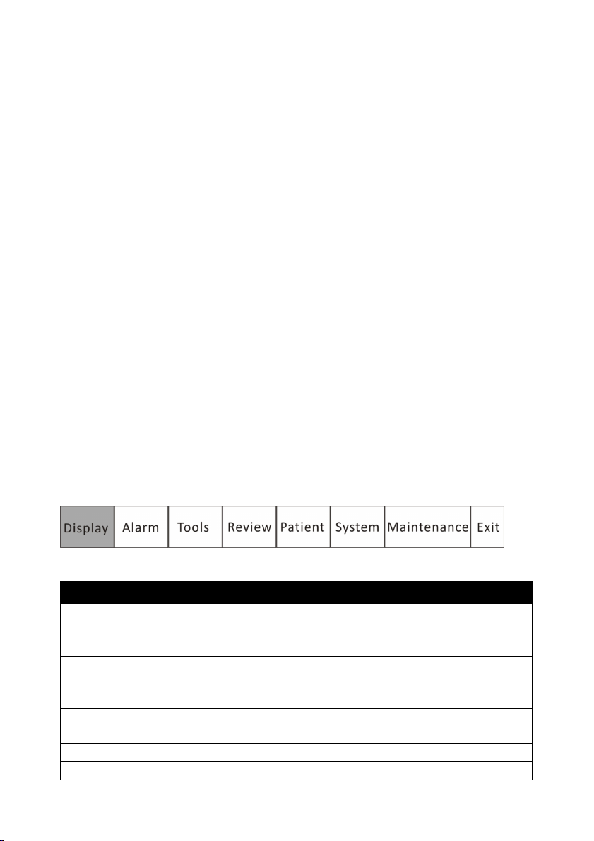
4.4 Basic Operation
Press the menu key to pop us the main menu. There are 8 options at the main
menu which shows as follow,
4-2 Veterinary Vital Signs Monitor Operation Manual
Figure 4.1: Main Menu
OPTIONS INSTRUCTION
Display Set the display modes.
Alarm Adjust the alarm limits for parameters, open/ close the
Tools Choose event and perform drug calculation.
Review Review the trend data, graph and alarms stored on the
Patient Select patient type, sex, add patient name, age and bed
System Setup system information.
Maintenance Back to default settings and conduct some maintenance
Page 35
Chapter 4: Setting up the Monitor
4.5 Systems Setup
Press the menu key to pop up the main menu and turn the rotary knob on the
monitor to move the cursor to the “System” option. Then press the rotary
knob to enter its submenu. The setup window will be shown as below,
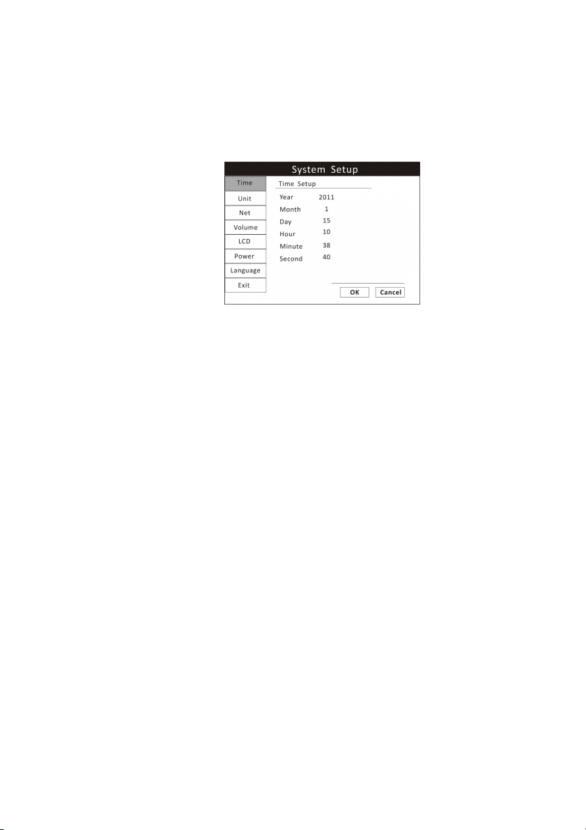
Figure 4.2: System Setup
4.5.1 Time Setup
If necessary, set the time and date on the display. The time and date indicator
is located in the lower right corner of the display. The monitor's real-time
clock and calendar keep track of the time and date, even when the monitor is
turned off or is not connected to AC power. The time and date stamp is used
for the NIBP tabular trends, the displayed and printed trends, and all other
printouts. The time display format is based on the 24-hour clock. For example,
5:00 a.m. is displayed as 5:00 and 5:00 p.m. is displayed as 17:00.
1. Press the menu key to pop up the main menu and turn the rotary knob to
move the cursor to the “System” option.
2. Push the rotary knob to access the “System” submenu. Turn the knob to
highlight the “Time” option.
3. Push the rotary knob to access the time setup submenu and turn the knob
to highlight the desired option.
4. Push the rotary knob to select the option. Turn the rotary knob to increase
or decrease the value. Press it again to move out.
5. Turn the rotary knob to “OK” or “Cancel” to save or delete your settings.
Veterinary Vital Signs Monitor Operation Manual 4-3
Page 36
Chapter 4: Setting up the Monitor
4.5.2 Unit Setup
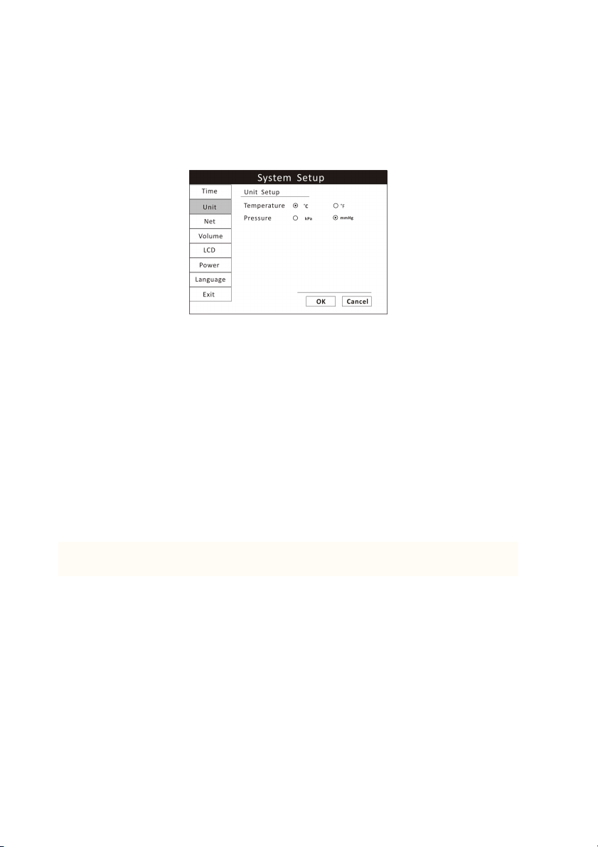
Units of measurement can be changed for TEMP and NIBP. The selected units
of measurement will remain in the monitor's memory until changed, even if
the monitor is turned off.
Figure 4.3: Unit Setup
1. Press the menu key to pop up the main menu and turn the rotary knob to
move the cursor to the “System” option.
2. Push the rotary knob to access the “System” submenu. Turn the knob to
highlight the “Unit” option.
3. Push the rotary knob to access the unit setup submenu and turn the knob to
highlight the desired unit and push to select.
TEMP can be changed to degrees Celsius (0C) to degrees Fahrenheit (0F).
•0C = 5× (0F - 32)/9
•0F = 9×0C /5+32
PRESSURE can be changed to millimeters of mercury (mmHg) or kilopascals
(kPa). The default setting is mmHg.
•kPa = mmHg X 0.133
•mmHg = kPa / 0.133
4. Turn the rotary knob to “OK” or “Cancel” button and push to save or delete
your settings.
4.5.3 Net Setup
4-4 Veterinary Vital Signs Monitor Operation Manual
Page 37
Chapter 4: Setting up the Monitor
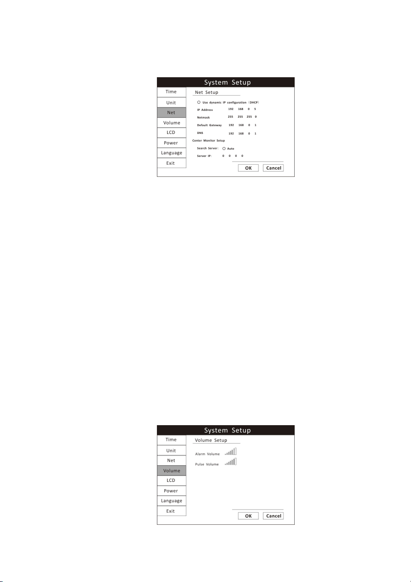
When connecting the monitor to a computer or a center monitor, you need to
setup the IP address.
Figure 4.4: Net Setup
1. Press the menu key to pop up the main menu and turn the rotary knob to
move the cursor to the “System” option.
2. Push the rotary knob to access the “System” submenu. Turn the knob to
highlight the “Net” option and push the knob to select.
3. You can choose to use dynamic IP configuration or set the IP address
manually.
4. Turn the rotary knob to “OK” or “Cancel” button and push to save or delete
your settings.
4.5.4 Volume Setup
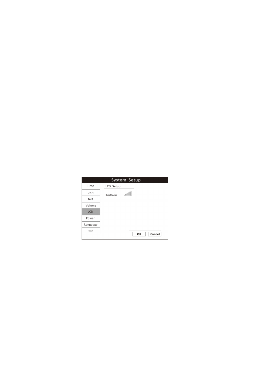
You can adjust the volume of the audible alarm and pulse rate to one of seven
levels separately. When an alarm occurs (and alarm silence is not enabled),
the alarm tones will sound at the chosen volume. The default alarm and pulse
volume settings are the fourth level. You cannot set the alarm volume to OFF.
Figure 4.5: Volume Setup
Veterinary Vital Signs Monitor Operation Manual 4-5
Page 38
Chapter 4: Setting up the Monitor
1. Press the menu key to pop up the main menu and turn the rotary knob to
move the cursor to the “System” option.
2. Push the rotary knob to access the “System” submenu. Turn the knob to
highlight the “Volume” option.
3. Push the rotary knob to access the volume setup submenu and turn the
knob to highlight the desired volume and push to select.
4. Turn the knob to increase or decrease the volume and push it to exit.
5. Turn the rotary knob to “OK” or “Cancel” button and push it to save or
delete your settings.
4.5.6 LCD Brightness Setup
You can set the brightness of the LCD display. There are seven levels of
brightness. And the default setting is the seventh level.
Figure 4.6: LCD Brightness Setup
1. Press the menu key to pop up the main menu and turn the rotary knob to
move the cursor to the “System” option.
2. Push the rotary knob to access the “System” submenu. Turn the knob to
highlight the “LCD” option.
3. Push the rotary knob to access the LCD setup submenu and turn the knob to
highlight the brightness and push to select.
4. Turn the knob to increase or decrease the level of brightness and push it to
exit.
4-6 Veterinary Vital Signs Monitor Operation Manual
Page 39
Chapter 4: Setting up the Monitor
5. Turn the rotary knob to “OK” or “Cancel” button and push it to save or
delete your settings.
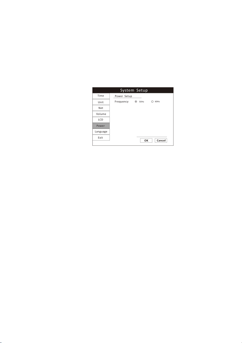
4.5.7 Power Setup
When the monitor is connected to an AC power source, the frequency should
be set relatively.
Figure 4.7: Power Setup
1. Press the menu key to pop up the main menu and turn the rotary knob to
move the cursor to the “System” option.
2. Push the rotary knob to access the “System” submenu. Turn the knob to
highlight the “Power” option.
3. Push the rotary knob to access the power setup submenu and turn the knob
to highlight the desired frequency and push to select.
4. Turn the rotary knob to “OK” or “Cancel” button and push it to save or
delete your settings.
4.5.8 Language Setup
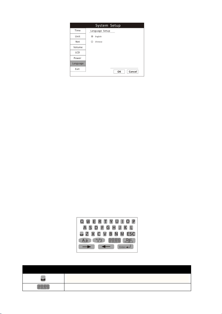
There are two languages available in this monitor: Chinese and English.
Veterinary Vital Signs Monitor Operation Manual 4-7
Page 40
Chapter 4: Setting up the Monitor
Figure 4.8: Language Setup
1. Press the menu key to pop up the main menu and turn the rotary knob to
move the cursor to the “System” option.
2. Push the rotary knob to access the “System” submenu. Turn the knob to
highlight the “Language” option.
3. Push the rotary knob to access the language setup submenu and turn the
knob to highlight the desired language and push to select.
4. Turn the rotary knob to “OK” or “Cancel” button and push it to save or
delete your settings.
4.6 Set Patient Information
4.6.1 How to use the keyboard
To enter characters and data to the monitor, the on-screen keyboard will be
used. If there is information needs to be entered, push the rotary knob and
then the on-screen keyboard will pop up.
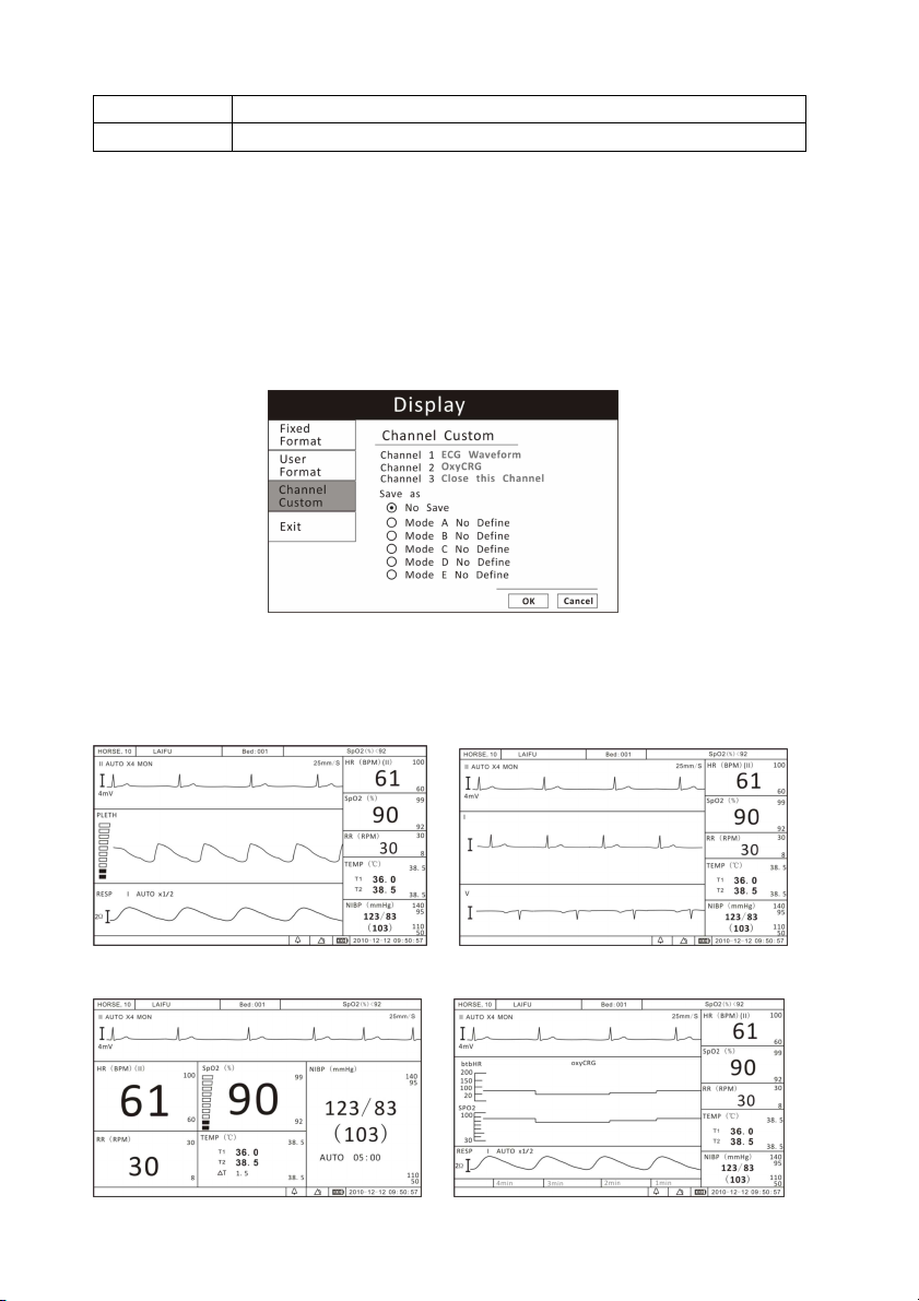
Figure 4.9: On-screen Keyboard
BUTTONS INSTRUCTION
Spacebar. Press it when a space is needed.
Press this key to access the character board.
4-8 Veterinary Vital Signs Monitor Operation Manual
Page 41

Chapter 4: Setting up the Monitor
switch between capital and lowercase letters.
Press this key to exit the character board.
Press it to change the character board into letters and
Press it to change the character board into numbers
and punctuation.
Delete button.
Press these two buttons to move the cursor.
Press it to confirm your writings.
4.6.2 Patient Setup
The monitor displays physiological data and stores it in the trends as soon as a
patient is connected. Before monitoring a patient, the doctor should input the
patient information correctly.
Figure 4.10: Patient Setup
When monitoring a cat or small animal, set the monitor to cat type. When
monitoring dogs or medium-size animals, set the monitor to the dog type.
When monitoring horses or large animals, set the monitor to the horse type.
1. Press the menu key to pop up the main menu and turn the rotary knob to
move the cursor to the “Patient” option and push to select.
2. Enter the patient information: select each field and use the on-screen
keyboard or choose from alternatives to input information.
ITEMS INSTRUCTION
NO.
Name
Bed Number
Sex
Enter the patient’s medical record number, for example 678.
Enter the patient’s first name and last name (family name).
Enter the patient’s bed number, for example: ICU007.
Choose Male or Female.
Veterinary Vital Signs Monitor Operation Manual 4-9
Page 42
Chapter 4: Setting up the Monitor
Age
Patient Type
Enter the patient’s age, for example: 10
Choose the patient’s type: DOG, CAT and HORSE.
3. Turn the rotary knob to “OK” or “Cancel” button and push it to save or
delete your settings.
4.7 Display Setup
Press the menu key to pop up the main menu and turn the rotary knob to
move the cursor to the “Display” option and push it to select.
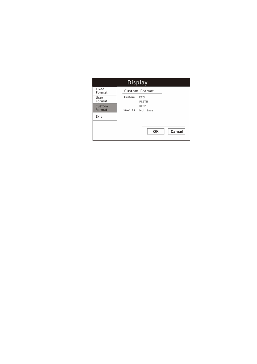
Figure 4.11: Display Setup
There are four main fixed display modes, and you can switch between them by
pressing the Mode key.
a). 1 ECG Display Mode
b). 3 ECG Display Mode
4-10 Veterinary Vital Signs Monitor Operation Manual
Page 43
Chapter 4: Setting up the Monitor
c). Huge Digit Display Mode
d). oxyCRG Display Mode
4.7.1 Customize Display Modes
Besides the above four main display modes, user can also customize the
display modes and save as user format modes.
Figure 4.12: Custom Format
1. Press the menu key to pop up the main menu and turn the rotary knob to
move the cursor to the “Display” option.
2. Push the rotary knob to access the “Display” submenu. Turn the knob to
highlight the “Custom Format” option.
3. Push the rotary knob to access the custom format submenu. There are
three waveform channels. You can customize each channel by choosing from
ECG, PLETH, Graph, Table, RESP or blank.
4. Push the rotary knob to select and choose the desired display option.
5. Turn the rotary knob to highlight “Not Save”, push to select and turn knob
to choose a format such as Format 1 to save your settings.
6. Turn the rotary knob to “OK” or “Cancel” button and push it to save or
delete your settings.
Veterinary Vital Signs Monitor Operation Manual 4-11
Page 44

Chapter 4: Setting up the Monitor
This Page is Intentionally Left Blank!
4-12 Veterinary Vital Signs Monitor Operation Manual
Page 45

Chapter 5: Monitoring the Patient
Chapter 5: Monitoring the Patient
Follow the steps in Chapter 4: Setting Up the Monitor; the remainder of this
chapter assumes that the monitor is properly installed and set up.
5.1 General Monitoring Instructions
Regardless of the parameters or measured values you want to monitor, follow
these steps when you are ready to attach a patient. Each step is further
explained in this chapter.
1. Attach the patient and sensors.
2. Choose the waveforms to be displayed.
3. Adjust the settings in the parameter boxes.
4. Set the high and low alarm limits.
5. Use these features as needed:
Responding to an alarm
NIBP Mode
Freeze Mode
Trends
Viewing Stored Trend Data
5.2 Attach the Patient
Attach the patient to the desired sensors and connect the sensor cables to the
monitor.
Parameters’ values will automatically appear on the display when the sensor
cable is connected to the monitor.
5.3 Adjust the Waveforms Settings
Choose the waveforms, trend table, graph or blank to be displayed in the three
waveform channels by using the Display Setup function and adjust the settings
of each waveform.
Push and turn the rotary knob on the monitor to move the cursor. Highlight
the waveform channel and push the knob to access the waveform menu in the
Veterinary Vital Signs Monitor Operation Manual
5-1
Page 46

Chapter 5: Monitoring the Patient
middle of the display. The settings available for selected waveform will be
displayed.
Refer the chapters dedicated to each parameter for more details regarding
waveform settings.
5.4 Adjust the Parameter Box Settings
1. Turn the rotary knob on the monitor to move the cursor. Highlight the
parameter box and push the knob to access the parameter menu in the middle
of the display. The settings available for the selected parameter will be
displayed.
2. Every parameter allows you to turn on or off its alarm detection capability
in the parameter menu. For example, if SpO2 alarm is on, an alarm will be
issued when the high or low alarm limit is violated. If you turn SpO2 alarm off
and the high or low alarm limit is violated, an alarm will not be issued.
NOTE! When you change the patient type or power down, this setting will
default to ON.
3. For the parameters where more than one measurement can be monitored
such as blood pressure (systolic, diastolic, and mean), only the settings of SYS
and DIA’s high and low limits can be displayed.
5.5 Set Alarm Limits
Set the high and low alarm limits for each parameter.
• When a numeric measured value matches or exceeds the high or low limit
set for that parameter, an alarm is issued. For example, if the low alarm limit
for SpO2 is 85 and the patient's measured value for SpO2 is 85 or less, an alarm
will be issued.
•The Vital Signs Monitor provides clinically appropriate default high and low
alarm limits for each numeric measured value. You can choose different high
and low limits, depending on the monitoring requirements of each patient. For
a list of default alarm limits, see Chapter 15: Specifications.
WARNING! Verify that alarm limits are clinically appropriate for your
patient and adjust according to institutional policy.
5-2 Veterinary Vital Signs Monitor Operation Manual
Page 47

Chapter 5: Monitoring the Patient
NOTE! Alarms may be tested while the monitor is in use by setting alarm
limits such that the measured value is outside the limits. Return
the alarm limits to their clinically appropriate settings after testing.
To set the high and low alarm limits:
1. Be sure that the sensor for each parameter is connected to the monitor, and
the parameter or measured value is shown on the display.
2. Press the menu key to pop up the main menu at the bottom of the display.
Turn the rotary knob on the monitor to move the cursor, highlight “Alarm” and
push the knob to select.
3. Highlight the name of each measured value and push the knob to select.
4. Highlight the high alarm limit and push the knob to select.
5. Turn the rotary knob to choose the desired value and push the knob to
select.
6. Turn the rotary knob to highlight the low alarm limit and push the knob to
select.
7. Turn the rotary knob to choose the desired value and push the knob to
select.
8. Turn the rotary knob to “OK” or “Cancel” button and push it to save or
delete your settings.
5. 6 Use these Features as Needed
5.6.1 Responding to an Alarm
1. When a numeric measured value matches or exceeds the high or low limit
set for that parameter, an alarm is issued. An audible alarm tone will sound,
alarm event will appear in the alarm status bar, and the violating measured
value will flash in the parameter box.
2. The alarming action will cease when the measured value is once again
within the alarm limits. Your monitor will either automatically stop alarming as
soon as the measured value returns to within the alarm limits, or it will require
you to manually acknowledge the alarm by pressing the alarm silence key.
Veterinary Vital Signs Monitor Operation Manual
5-3
Page 48
Chapter 5: Monitoring the Patient
NOTE! Only qualified personnel may silence the alarm temporarily, or
enable it indefinite.
3. If the alarm limit is still violated after two minutes, the audible alarm tone
will sound again. If, within the two minutes of alarm silence, another
measured value matches or exceeds its alarm limits, the alarming action will
resume, including the audible alarm tone.
4. If it is appropriate for your patient, you can turn off the alarm detection
capability for a single parameter so that when the measured value matches or
exceeds the alarm limits, the monitor will not issue an alarm.
5.6.2 NIBP Mode
Non-invasive blood pressure (NIBP) measurements can be made in automatic,
manual, or STAT modes. In the automatic mode, the monitor will measure the
patient's NIBP periodically, according to the interval you select. In the manual
mode, the monitor will measure the patient's NIBP only when you press the
NIBP key. In the STAT mode, the monitor will measure the patient's NIBP
continuously for five minutes.
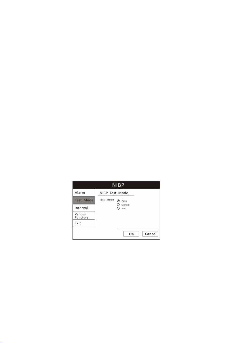
Figure 5.1: NIBP Mode
To change the NIBP mode:
1. Push and turn the rotary knob on the monitor to move the cursor. Highlight
the NIBP parameter box and push to select.
2. Highlight the test mode and push the rotary knob select.
3. Turn the rotary knob to choose a mode (Auto, Manual, or Stat), and push
the knob to select.
5-4 Veterinary Vital Signs Monitor Operation Manual
Page 49

Chapter 5: Monitoring the Patient
5.6.3 Freeze Mode
Use this feature to temporarily hold or freeze all current waveforms, even
those that are not displayed. Monitoring does not stop; you can still view the
current measured values in the parameter boxes.
When you freeze the waveforms, you may not adjust any waveform settings.
In addition, attempting to perform any other functions will cause the freeze
mode to be cancelled. For example, if you freeze the waveforms and then
select ALARMS from the main menu, the alarm limits box will be displayed in
the waveform area and the waveforms will no longer be in freeze mode.
To freeze the waveforms:
1. Press the Freeze key on the right side of the monitor. The waveforms will
stop, or freeze.
2. Press the “Page Up” or “Page Dn” to browse the waveform and press “Save”
to store the frozen waveform section in a file.
3. To start the waveforms again, press the Freeze Key again.
5.6.4 Trends
The monitor stores tabular trend data graph every 10 seconds for up to 120
hours for the following parameters:
a. ECG
• Heart Rate
• ST
b. Oximetry
• Oxygen saturation (SpO2)
• Pulse rate, when SpO
is the selected heart rete source
2
c. Non-invasive blood pressure (NIBP) (systolic, diastolic, mean)
d. Temperature (T1 and T2)
Veterinary Vital Signs Monitor Operation Manual
5-5
Page 50
Chapter 5: Monitoring the Patient
be displayed in the trend graph display area.
of this range. Any value over the limit is not valid.
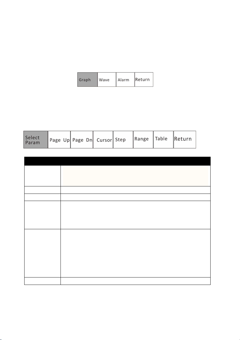
5.6.5 Viewing Stored Trend Data
To view the stored trend data, press the menu key and turn the rotary knob on
the monitor to move the cursor to “Review” option and push to access the
review submenu shown as below.
1. Review Trend Graph
In the review submenu, highlight the “Graph” and push the rotary knob to
select. The monitor will display the trend graph and the following menu.
ITEMS INSTRUCTION
Select
Parameter
Select a parameter: HR, ST, SpO2, NIBP, RR, or T1/T2 and push
the rotary knob to select. The corresponding trend graph will
Page up/ Dn
Cursor
Browse the time frame of the trend graph.
Use to select points on the trend graph.
Step Select the time intervals between data points. The trend
graph will be adjusted accordingly. The available time
intervals are 1 second, 5 seconds, 10 seconds, 20 seconds, 30
seconds, 60 seconds, 90 seconds and 120 seconds.
Range
It is used to designate the Y axis value range of the trend
graph. The adjusted range will be stored in the monitor and
will be applied when the monitor restarts. The range has
three adjustment modes: alarm limit range, maximum range,
and manual adjustment. Once the user sets the range, the
trend graph displays data within the upper limit/lower limit
Table
Select this option to access the trend table display.
2. Review Trend Table
5-6 Veterinary Vital Signs Monitor Operation Manual
Page 51
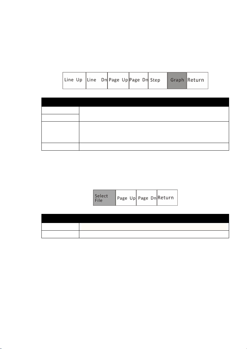
Chapter 5: Monitoring the Patient
minutes, 20 minutes, 30 minutes and 1 hour.
The information in the trend table is displayed as a list. The available number
and categories of parameters are the same as with the trend graph. In the
trend table, the median time is the cursor time value in the trend graph. The
value of each parameter is date and time (except NIBP). The NIBP value is the
first value in the current interval.
ITEMS INSTRUCTION
Line Up/Dn
Browse the time frame.
Page Up/ Dn
Step
The trend table’s data compress or append according to
step. The available steps are 1 minute, 5 minutes, 10
Graph
Select this option to back to the trend graph display.
3. Review Freeze Wave
In the review submenu, highlight the “Wave” and push the rotary knob to
select. The following menu will be displayed:
ITEMS INSTRUCTION
Select File
Page up/ Dn
Select a saved file to review.
Browse frozen waveform page by page.
4. Review Alarms
The user can review 1000 alarm records.
In the review submenu, highlight the “Alarm” and push the rotary knob to
select. The monitor will display the stored alarms for all the parameters.
Veterinary Vital Signs Monitor Operation Manual
5-7
Page 52

Chapter 5: Monitoring the Patient
This page is intentionally left blank!
5-8 Veterinary Vital Signs Monitor Operation Manual
Page 53

Chapter 6: Alarms
Chapter 6: Alarms
6.1 Parameter Alarms and Technical Alarms
A parameter alarm occurs when a numeric measured value matches or
exceeds the high or low limit set for that parameter.
A technical alarm occurs when there is a malfunction with any of the sensors
or connections, or when the battery is low or when an error is detected during
self-test.
During an alarm, an audible alarm tone will sound and a message will be
displayed in the alarm status bar at the top of the display. For parameter
alarms, the violating measured value will flash.
6.2 High, Medium, and Low Priority Alarms
Caution! Only qualified doctors can set the physiological parameters’
upper limits for alarm level according to patient's conditions.
Alarms are categorized as high priority, medium priority, or low priority.
High Priority Alarms
A high priority alarm sound consists of two bursts of five single tones over a
four-second interval. The sequence is repeated every ten seconds. High
priority alarms supersede all other alarms. The alarm message will be
displayed in the alarm status bar with a red flashing background; the violating
measured value will flash in red.
CAUTION! When different priority alarms occur simultaneously, only the
highest priority alarm is displayed.
Medium Priority Alarms
A medium priority alarm sound consists of two bursts of three single tones
that repeats every 18 seconds. The alarm message will be displayed in the
alarm status bar with a yellow flashing background; the violating measured
value will flash in red.
Low Priority Alarms
Veterinary Vital Signs Monitor Operation Manual 6-1
Page 54

Chapter 6: Alarms
A
larm
C
ontent
Type
Priority
HR Ov
er limit
above medium
SpO2
Over limit
above medium
ST Over limit
RR Over limit
NIBP Over limit
Temperature
Over limit
(SpO2) pulse search over due
Parameter
alarm
high
(ECG)
lead off
Technical alarm
high
(ECG) channel full
Technical alarm
high
(SpO2) sensor off
Technical alarm
high
(SpO2) without sensor
Technical alarm
high
(NIBP) cuff leakage
Technical alarm
high
(NIBP) without cuff
Technical alarm
high
(NIBP) cuff over pressure
Technical alar
m high
(NIBP) test over time limit
Technical alarm
high
A low priority alarm sound consists of a single burst of one single tone that
repeats every 20 seconds. The alarm message will be displayed in the alarm
status bar with a yellow flashing background; the violating measured value will
not flash.
Alarm Priority Chart
Set priority
based on
patient
conditions
6.3 Controlling Alarms
You can control many factors in the way the monitor issues an alarm. You can
turn off the alarm detection capability for a single parameter. You can change
the high and low alarm limits. You can quickly reset the alarm limits relative to
the patient's current measured values. You can control the volume of the
audible alarm. And you can silence an alarm for two minutes, or indefinitely.
CAUTION! When the overall alarm is switched off and physiological
parameters exceed limits, there will be no alarm sound and no
blinking numerics. The words relating to the technical alarm will
blink but without audible sound
WARNING! User should pay careful attention to overall alarm switching.
Switching off the overall alarm is not recommended.
6-2 Veterinary Vital Signs Monitor Operation Manual
.
Page 55
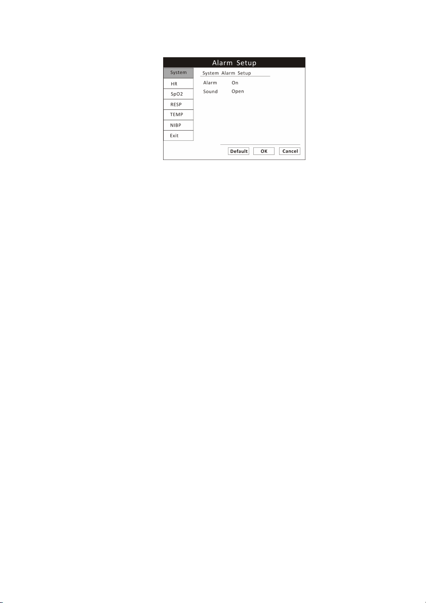
Chapter 6: Alarms
Figure 6.1: Alarm Setup
To change alarm settings,
1. Press the menu key to pop up the main menu and turn the rotary knob to
move the cursor to the “Alarm” option and push the knob to select.
2. Highlight the “System” option and push to select. You can turn on/off
overall alarm switches for all the parameters. You can also silence the overall
alarm sound temporarily or indefinitely.
3. To change of alarm settings for a single parameter, you can highlight each
parameter option and change the settings according. Or you can access their
parameter menu to change the settings.
4. Turn the rotary knob to “OK” or “Cancel” button and push to save or delete
your settings.
6.3.1 Change alarm limits
The monitor provides clinically appropriate default high and low alarm limits
for each numeric measured value. You can change the high and low alarm
limits, depending on the monitoring requirements of each patient. You can
even set a high or low alarm limit to OFF, so that no alarm will be issued.
Check the list of default alarm limits at the chapter of specification.
WARNING! Alarm high limit cannot be lower than low limit. If high limit is
lower than low limit, the monitor will not respond.
WARNING! When the monitor is turned on for the first time, it will default
to the alarm configuration for a horse.
Veterinary Vital Signs Monitor Operation Manual 6-3
Page 56

Chapter 6: Alarms
WARNING! The alarm settings are set to factory defaults. Once reset
according to patient conditions, current alarm settings are
saved for up to 30 minutes after the monitor is turned off. If
the monitor is not turned back on for 30 minutes, alarm limits
are automatically reset to factory defaults.
WARNING! If patient information has been reset, the user should reset
alarm limits based on new “patient type”.
6.3.2 Silence alarms
The monitor is set to allow temporary or indefinite audio alarm silence, then
pressing the Alarm Silence key in turn while audible alarms are enabled will do
one of the following:
•
Press the Alarm Silence key once. A 30-seconds timer will appear at the right
side of the Alarm Since icon. Audible alarms will not be re-enabled if any new
alarm occurs. They will only be re-enabled if the 30-seconds timer times out,
or if the Alarm Silence key is pressed again.
•
Press the Alarm Silence key twice. A 60-seconds timer will appear at the right
side of the Alarm Since icon. Audible alarms will not be re-enabled if any new
alarm occurs. They will only be re-enabled if the 60-seconds timer times out,
or if the Alarm Silence key is pressed again.
•
Press the Alarm Silence key for three times. A 90-seconds timer will appear at
the right side of the Alarm Since icon. Audible alarms will not be re-enabled if
any new alarm occurs. They will only be re-enabled if the 90-seconds timer
times out, or if the Alarm Silence key is pressed again.
•
Press the Alarm Silence key for four times. A 120-seconds timer will appear at
the right side of the Alarm Since icon. Audible alarms will not be re-enabled if
any new alarm occurs. They will only be re-enabled if the 120-seconds timer
times out, or if the Alarm Silence key is pressed again.
•
Press the Alarm Silence key for five times. The Alarm Since icon will be
displayed with a cross and no timer. Audible alarms will not be re-enabled if
any new alarm occurs. They will only be re-enabled if the Alarm Silence key is
pressed again.
NOTE! Only qualified personnel may change the allowed alarm audio
silence mode.
6-4 Veterinary Vital Signs Monitor Operation Manual
Page 57

Chapter 7: ECG
Chapter 7: ECG
7.1 ECG Measurement Capability
The Vital Signs Monitor provides continuous five-lead ECG processing with
standard lead selections and filtering from electrocautery discharge. The heart
rate measured value (HR) and primary lead messages are displayed in the HR
parameter box, and a waveform for the primary ECG lead is continuously
displayed.
7.2 ECG Warnings, Cautions, and Notes
WARNING! Connect only five-lead ECG lead wires from the patient to the
ECG patient cable. Do not connect any other signal source to
the ECG patient cable.
WARNING! This monitor does not identify or interpret arrhythmia events.
The indication of heart rate may be adversely affected by the
presence of cardiac arrhythmias.
CAUTION! Only five-lead ECG cable can be used to this monitor. Using the
incorrect cable for the selected mode might lead to a floating
reference or additional noise on the ECG signal.
NOTE! Follow institutional standards when applying ECG electrodes.
Silver/Silver Chloride disposable electrodes are strongly
recommended to avoid polarization effects that result in large
input offset potentials. Use of "squeeze bulb" type electrodes is
not recommended.
NOTE! Line isolation monitor transients may resemble actual cardiac
waveforms and thus inhibit heart rate alarms.
7.3 Theory of Operation
Electrical currents influenced by the cardiac impulse flow through the body
tissue around the heart. Three or five electrodes, placed on the skin on
opposite sides of the heart, transmit the electrical potentials to circuitry in the
monitor.
Veterinary Vital Signs Monitor Operation Manual 7-1
Page 58

Chapter 7: ECG
The monitor's ECG circuitry amplifies, filters, and digitizes (converts analog
signals to digital signals) the received electrical potentials. The digitized signals
are used to display the ECG waveform and calculate the ECG heart rate
7.4 Attaching the Patient
NOTE! Follow institutional standards when applying ECG electrodes.
NOTE! The monitor is protected against damage from defibrillator,
diathermy, and electrocautery discharge.
1. Skin Preparation for Electrode Placement
Good electrode-to-skin contact is important for a good ECG signal, as the skin
is a poor conductor of electricity.
a)
Select sites with intact skin, without impairment of any kind.
b)
Clip or shave hair from sites as necessary.
c)
Wash sites thoroughly with soap and water, leaving no soap residue.
We do not recommend using ether or pure alcohol, because this dries the skin
and increases the resistance.
d)
Dry skin thoroughly by rubbing briskly to increase capillary blood flow in the
tissues.
e)
Use ECG skin preparation (abrasive) paper to remove dead skin cells and to
improve the conductivity of the electrode site.
2. Connecting ECG Leads
a)
Attach the clips or snaps to the electrodes before placing them. If you are
not using pre-gelled electrodes, apply electrode gel to the electrodes before
placement.
b)
Place the electrodes on the patient.
NOTE! To remove the ECG cable, grip the connector and pull back firmly.
DO NOT pull on the ECG cable to remove the ECG connector from
the monitor.
7-2 Veterinary Vital Signs Monitor Operation Manual
Page 59
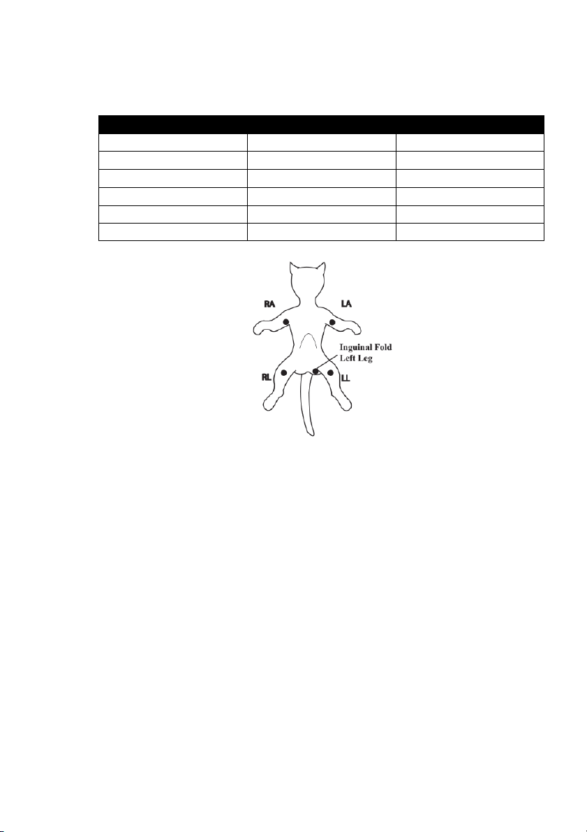
Chapter 7: ECG
V 4the Intercostal(left)
Brown
Standard 5-Lead Placement
ECG 5-LEAD ELECTRODE INDENTIFICATION
Electrode Label Location Color
RA Right Arm White
RL Right Leg Green
LA Left Arm Black
LL Left Leg Red
Figure 7.1: 5-Lead Placement
WARNING! Electrodes of dissimilar metals should not be used.
CAUTION! To protect the monitor from damage during defibrillation, for
accurate ECG information and to protect against noise and other
interference, use only ECG electrodes and cables specified by
Utech.
3. Place the ECG leads to the patient. Be sure that the leads are in the correct
ECG cable position. The ECG leads and patient cable connector are
color-coded.
CAUTION! Ensure conductive parts, including electrodes of the patient
cable, do not come into contact with any conductive surfaces or
earth parts.
Veterinary Vital Signs Monitor Operation Manual 7-3
Page 60
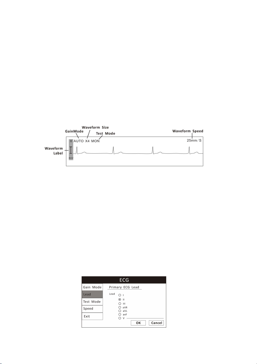
Chapter 7: ECG
The monitor will automatically detect when the ECG cable is connected. Heart
rate (HR) will be displayed in the HR parameter box and the primary ECG
waveform will appear on the waveform channel.
7.5 Choosing the Waveform Settings
Use the ECG waveform menu options to choose the primary ECG lead and
adjust the settings for the size and speed of the ECG waveform.
7.5.1 Access the ECG Waveform Menu
The ECG waveform menu is accessible from any ECG waveform channel.
Figure 7.2: ECG Display
To access the ECG waveform menu from the waveform channel:
1. Push and turn the rotary knob on the monitor to move the cursor.
2. Highlight the waveform channel for primary ECG lead and push the knob to
select. The ECG waveform menu will appear in the middle of the display.
7.5.2 Change the Primary ECG Lead
Lead II is the default primary lead. You can designate any other lead to be the
primary using the ECG waveform menu. The selected primary lead will be
displayed in the waveform label.
Figure 7-3: Set Primary ECG Lead
7-4 Veterinary Vital Signs Monitor Operation Manual
Page 61
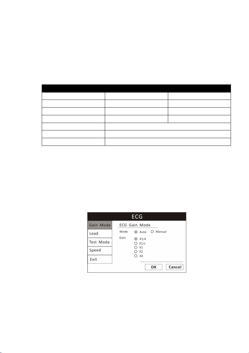
Chapter 7: ECG
To change the primary lead:
1. On the ECG waveform menu, highlight LEAD and push the knob to access
the ECG leads submenu.
2. Highlight the desired primary ECG lead and push the knob to select. See the
following tables for the primary lead configuration.
ECG 5-LEAD CONFIGURATION
I Lead I Configuration RA-LA
II Lead II Configuration RA-LL
III Lead III Configuration LA-LL
V Lead V Configuration LA-V
AVF Augmented Lead AVF
AVL Augmented Lead AVL
AVR Augmented Lead AVR
3. Turn the rotary knob to “OK” or “Cancel” to save or delete your settings.
7.5.3 Choose the Waveform Size
If any of the displayed ECG waves is too small or clipped, you can change the
size of the ECG waveforms on the display. The selected size (X1/4, X1/2, X1, X2,
or X4) will appear in the waveform channel. The default size is times one (X1).
Figure 7.4: Choose Waveform Size
To change the size of the ECG waveform:
1. On the ECG waveform menu, highlight Gain Mode and push the knob to
select.
Veterinary Vital Signs Monitor Operation Manual 7-5
Page 62
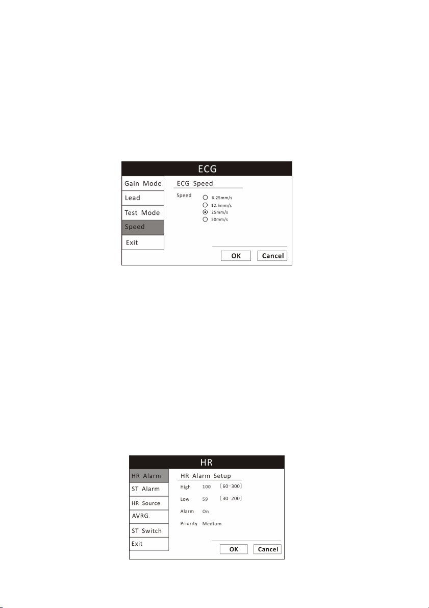
Chapter 7: ECG
2. Highlight the desired size of the waveform (X1/4, X1/2, X1, X2, or X4) and
push the knob to select.
3. Turn the rotary knob to “OK” or “Cancel” to save or delete your settings.
7.5.4 Choose the Waveform Speed
You can choose the speed at which the ECG waveform is updated.
Figure 7.5: Choose Waveform Speed
To change the speed of the ECG waveform:
1. On the ECG waveform menu, highlight Speed and push the knob to select.
2. Highlight the desired speed of the waveform (6.25, 12.5, 25, or 50
mm/second) and push the knob to select.
3. Turn the rotary knob to “OK” or “Cancel” to save or delete your settings.
7.6 Adjusting the Settings in the Parameter Box
7.6.1 HR Alarm Setup
7-6 Veterinary Vital Signs Monitor Operation Manual
Page 63

Chapter 7: ECG
Figure 7.6: HR Alarm Setup
1. Turn Alarm Detection On or Off
You can turn on or off the alarm detection capability for the heart rate value.
If HR ALARMS is on, an alarm will be issued when the high or low alarm limit is
violated. If you turn HR ALARMS off and the high or low alarm limit is violated,
an alarm will not be issued. When you turn off the monitor and turn it on
again, HR ALARMS will be reset to ON; the default setting is ON. See Choose
the Heart Rate Source in this chapter for information regarding the source of
the measured value for heart rate.
To turn on or off the heart rate alarm detection:
a)
Push and Turn the rotary knob on the monitor to move the cursor. Highlight
the HR parameter box and push the knob to access the HR parameter menu.
b)
Highlight HR ALARM and push the knob to select.
c)
Choose ON or OFF and push the knob to select.
d)
Turn the rotary knob to “OK” or “Cancel” to save or delete your settings.
2. Set High and Low Alarm Limits
a)
Push and Turn the rotary knob on the monitor to move the cursor. Highlight
the HR parameter box and push the knob to access the HR parameter menu.
b)
Highlight HR ALARM and push the knob to select.
c)
Move the cursor to High/Low and push the knob to select.
d)
Turn the knob to increase or decrease the number and push it to confirm.
e)
Turn the rotary knob to “OK” or “Cancel” to save or delete your settings.
3. Choose Alarm Priority
a)
Push and Turn the rotary knob on the monitor to move the cursor. Highlight
the HR parameter box and push the knob to access the HR parameter menu.
b)
Highlight HR ALARM and push the knob to select.
Veterinary Vital Signs Monitor Operation Manual 7-7
Page 64
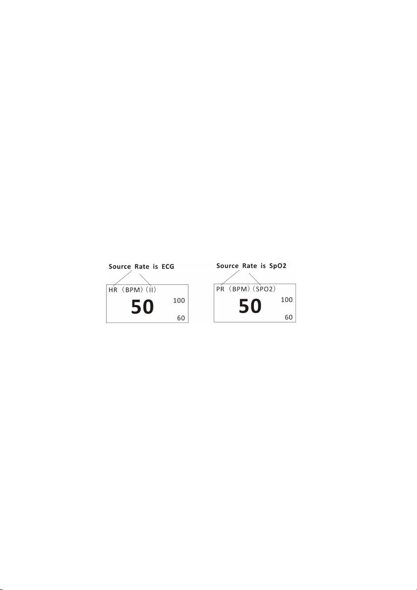
Chapter 7: ECG
c)
Choose Senior, Junior or Medium and push the knob to select.
d)
Turn the rotary knob to “OK” or “Cancel” to save or delete your settings.
7.6.2 Choose the Heart Rate Source
The Vital Signs Monitor can measure the heart/pulse rate using two different
parameters: ECG and oximetry (SpO2). Regardless of the source, the measured
value for heart rate can be continuously displayed in the HR parameter box.
You can choose the source (AUTO, ECG or SPO2) of the heart/pulse rate
displayed. The default setting is AUTO.
If you choose ECG, the primary lead label (II) will show in the HR parameter
box at the detection of each QRS complex in the waveform. If you choose SpO2
as the source, the SPO2 label identifying the source will be displayed in the HR
parameter box at the detection of a pulse.
Figure 7.7: Heart Rate Source
If you choose AUTO, the monitor will determine the best source depending on
the quality of available data and the following source priority:
a. If the ECG cable is connected to the monitor, and the ECG reading is valid,
then ECG will be the heart rate source.
b. If ECG cable is not connected or the signal is otherwise undetected, an
oximetry cable (SpO2) is connected to the monitor, and the SpO2 reading is
valid, then SpO2 will be the heart rate source.
To choose the source of the heart rate displayed in the HR parameter box:
7-8 Veterinary Vital Signs Monitor Operation Manual
Page 65
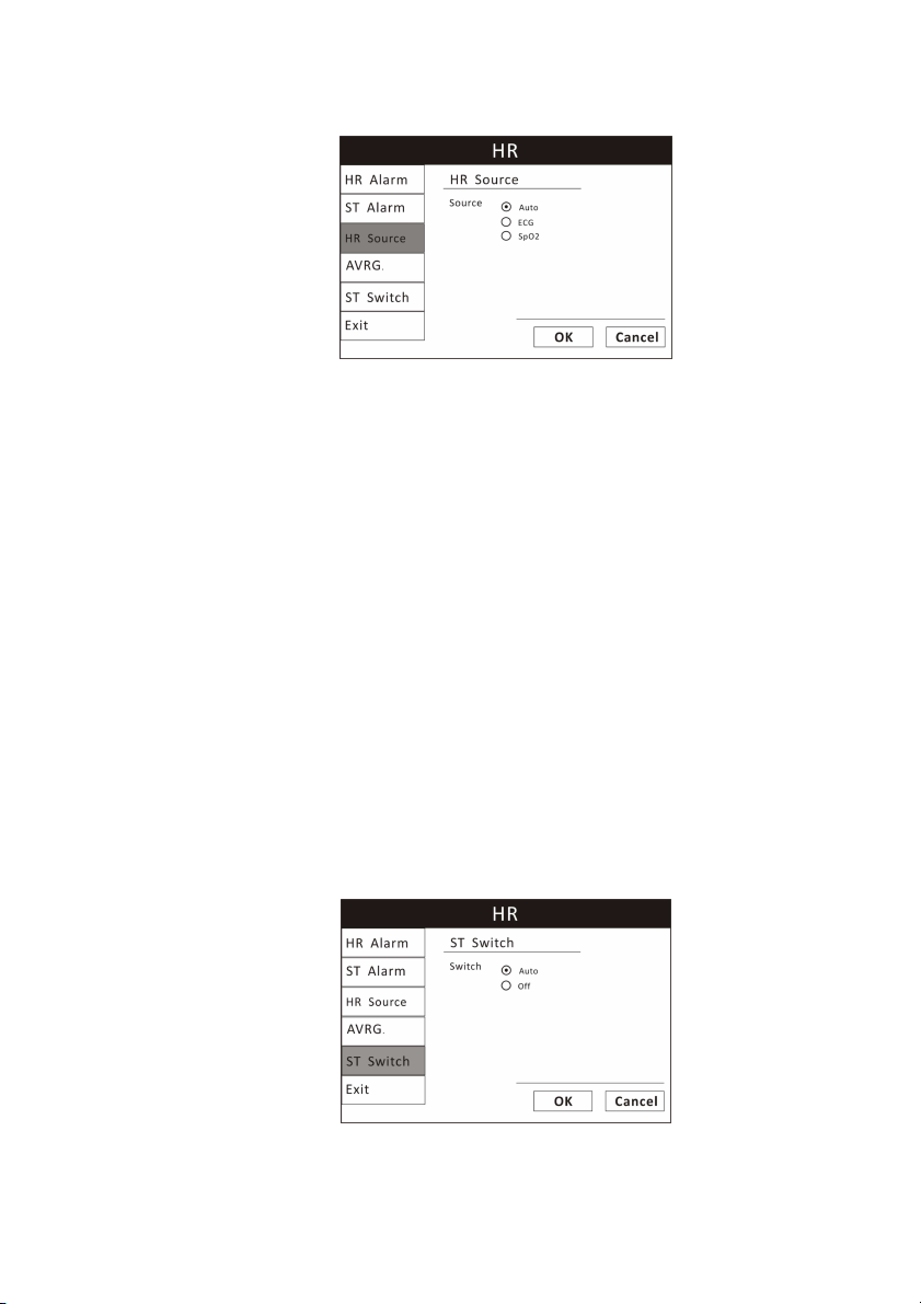
Chapter 7: ECG
Figure7.8: Choose HR Source
1. Push and turn the rotary knob on the monitor to move the cursor. Highlight
the HR parameter box and push the knob to access the HR parameter menu.
2. Highlight HR Source and push the knob to select.
3. Choose the desired source of the measured value for heart rate (AUTO, ECG,
or SpO2) and push the knob to select.
4. Turn the rotary knob to “OK” or “Cancel” to save or delete your settings.
7.7 Monitoring ST
The monitor performs ST segment analysis on normal and atrially paced beats
and calculates ST segment elevations and depressions. This information can be
displayed in the form of ST numerics and snippets on the monitor.
7.1.1 Turn on the ST Switch
Figure7.9: Turn on ST Switch
Veterinary Vital Signs Monitor Operation Manual 7-9
Page 66
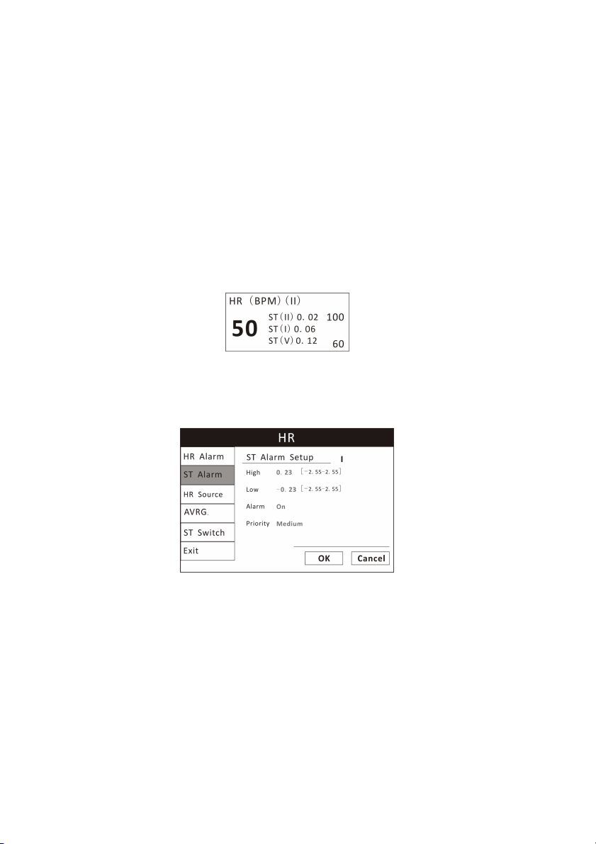
Chapter 7: ECG
1. Push and turn the rotary knob on the monitor to move the cursor. Highlight
the HR parameter box and push the knob to access the HR parameter menu.
2. Highlight the ST switch and push the knob to select.
3. Choose AUTO or OFF and push the rotary knob to select.
4. Turn the rotary knob to “OK” or “Cancel” to save or delete your settings.
7.1.2 ST Display
The ST section will be displayed in the HR parameter box after you turn on the
ST switch.
Figure 7.10: ST Display
7.1.3 ST Alarm Setup
Figure 7.11: ST Alarm Setup
1. Turn Alarm Detection On or Off
You can turn on or off the alarm detection capability for the heart rate value.
If ST ALARMS is on, an alarm will be issued when the high or low alarm limit is
violated. If you turn ST ALARMS off and the high or low alarm limit is violated,
an alarm will not be issued. When you turn off the monitor and turn it on
again, ST ALARMS will be reset to ON; the default setting is ON.
To turn on or off the ST alarm detection:
7-10 Veterinary Vital Signs Monitor Operation Manual
Page 67

Chapter 7: ECG
a)
Push and Turn the rotary knob on the monitor to move the cursor. Highlight
the HR parameter box and push the knob to access the HR parameter menu.
b)
Highlight ST ALARM and push the knob to select.
c)
Choose the source of ST section from lead I, II, III, aVR, aVL, aVF, V.
d)
Choose ON or OFF and push the knob to select.
e)
Turn the rotary knob to “OK” or “Cancel” to save or delete your settings.
2. Set High and Low Alarm Limits
a)
Push and Turn the rotary knob on the monitor to move the cursor. Highlight
the HR parameter box and push the knob to access the HR parameter menu.
b)
Highlight ST ALARM and push the knob to select.
c)
Move the cursor to High/Low and push the knob to select.
d)
Turn the knob to increase or decrease the number and push it to confirm.
e)
Turn the rotary knob to “OK” or “Cancel” to save or delete your settings.
3. Choose Alarm Priority
a)
Push and Turn the rotary knob on the monitor to move the cursor. Highlight
the HR parameter box and push the knob to access the HR parameter menu.
b)
Highlight ST ALARM and push the knob to select.
c)
Choose Senior, Junior or Medium and push the knob to select.
d)
Turn the rotary knob to “OK” or “Cancel” to save or delete your settings.
Veterinary Vital Signs Monitor Operation Manual 7-11
Page 68

Chapter 7: ECG
This Page is intentionally left blank!
7-12 Veterinary Vital Signs Monitor Operation Manual
Page 69

Chapter 8: Oximetry
Chapter 8: Oximetry
8.1 Oximetry Measurement Capability
The oximetry parameter provides the continuous non-invasive monitoring of
oxygen saturation (%SpO2) in the blood and peripheral pulse rate (PPR). The
measured values for oximetry (%SpO2 and PPR) and a pulse strength bar graph
are displayed in the SpO2 parameter box. A plethysmogram, or oxygen
saturation waveform can be continuously displayed. A variety of reusable
sensors is available for monitoring patients.
8.2 Oximetry Warnings, Cautions, and Notes
WARNING! Prolonged use or the patient's condition may require changing
the sensor site periodically. Change the sensor site and check
skin integrity, circulatory status, and correct alignment at least
every 4 hours.
WARNING! When attaching sensors with micro foam tape, do not stretch
the tape or attach the tape too tightly. Tape applied too tightly
may cause inaccurate readings and blisters on the patient's
skin (lack of skin respiration, not heat, causes the blisters).
WARNING! Using a damaged sensor may cause inaccurate readings,
possibly resulting in patient injury or death. Inspect each
sensor. If a sensor appears damaged, do not use it. Use another
sensor or contact your authorized repair center for help.
WARNING! Using a damaged patient cable may cause inaccurate readings,
possibly resulting in patient injury or death. Inspect the patient
cable. If the patient cable appears damaged, do not use it.
Contact your authorized repair center for help.
WARNING! If any of the integrity checks fail, do not attempt to monitor
the patient. Use another sensor or patient cable, or contact the
equipment dealer for help if necessary.
WARNING! Do not autoclave, ethylene oxide sterilize, or immerse the
sensors in liquid. Evidence that liquid has been allowed to
enter the monitor voids the warranty.
Veterinary Vital Signs Monitor Operation Manual 8-1
Page 70

Chapter 8: Oximetry
WARNING! Use only SpO2 sensors supplied with, or specifically intended
for use with, this device.
WARNING! SpO2 measurements may be adversely affected in the presence
of high ambient light. Shield the sensor area (with a surgical
towel, for example) if necessary.
WARNING! Dyes introduced into the bloodstream, such as methylene blue,
indocyanine green, indigo carmine, patent blue (PBV), and
fluorescein may adversely affect the accuracy of the SpO2
reading.
WARNING! Any condition that restricts blood flow, such as use of a blood
pressure cuff or extremes in systemic vascular resistance, may
cause an inability to determine accurate SpO2 and pulse rate
readings.
CAUTION! Unplug the sensor from the monitor before cleaning or
disinfecting.
NOTE! Obstructions or dirt on the sensor's red light or detector may cause
a sensor failure. Make sure there are no obstructions and the
sensor is clean.
8.3 Pulse Oximetry Theory of Operation
The pulse oximeter determines %SpO2 and pulse rate by passing two
wavelengths of low intensity light, one red and one infrared, through body
tissue to a photodetector. Information about wavelength range can be
especially useful to clinicians. Wavelength information for this device can be
found in the
SpO2 Specifications
section of this manual.
Pulse identification is accomplished by using plethysmographic techniques,
and oxygen saturation measurements are determined using
spectrophotometric oximetry principles. During measurement, the signal
strength resulting from each light source depends on the color and thickness
of the body tissue, the sensor placement, the intensity of the light sources,
and the absorption of the arterial and venous blood (including the time
varying effects of the pulse) in the body tissues.
8-2 Veterinary Vital Signs Monitor Operation Manual
Page 71

Chapter 8: Oximetry
1
Figure 8.1: Theory of Operation
2
1. Low intensity Red and Infrared LED light sources
2. Detector
Oximetry processes these signals, separating the time invariant parameters
(tissue thickness, skin color, light intensity, and venous blood) from the time
variant parameters (arterial volume and SpO2) to identify the pulses and
calculate functional oxygen saturation. Oxygen saturation calculations can be
performed because blood saturated with oxygen predictably absorbs less red
light than oxygen-depleted blood.
WARNING! Since measurement of SpO2 depends on a pulsating vascular
bed, any condition that restricts blood flow, such as the use of
a blood pressure cuff or extremes in systemic vascular
resistance, may cause an inability to determine accurate SpO2
and pulse rate readings.
WARNING! Under certain clinical conditions, pulse oximeters may display
dashes if unable to display SpO2 and/or pulse rate values.
Under these conditions, pulse oximeters may also display
erroneous values. These conditions include, but are not limited
to: patient motion, low perfusion, cardiac arrhythmias, high or
low pulse rates or a combination of the above conditions.
Failure of the clinician to recognize the effects of these
conditions on pulse oximeter readings may result in patient
injury.
8.4 Attaching the Patient
WARNING! Prolonged use or the patient's condition may require changing
the sensor site periodically. Change the sensor site and check
skin integrity, circulatory status, and correct alignment at least
Veterinary Vital Signs Monitor Operation Manual 8-3
Page 72

Chapter 8: Oximetry
every 4 hours.
WARNING! When attaching sensors with Microfoam tape, do not stretch
the tape or attach the tape too tightly. Tape applied too tightly
may cause inaccurate readings and blisters on the patient's
skin (lack of skin respiration, not heat, causes the blisters).
1. Choose a sensor to be used to monitor oximetry.
2. Clean and disinfect the sensor. Use a soft cloth moistened in water or a mild
soap solution, and then wipe the sensor with isopropyl alcohol.
WARNING! Do not autoclave, ethylene oxide sterilize, or immerse the
sensors in liquid. Evidence that liquid has been allowed to
enter the monitor voids the warranty.
CAUTION! Unplug the sensor from the monitor before cleaning or
disinfecting.
NOTE! Obstructions or dirt on the sensor's red light or detector may cause
a sensor failure. Make sure there are not obstructions and the
sensor is clean.
3. Check the sensor to make sure it do not appear damaged.
WARNING! Using a damaged sensor may cause inaccurate readings,
possibly resulting in patient injury or death. Inspect each
sensor. If a sensor appears damaged, do not use it. Use another
sensor or contact your authorized repair center for help.
WARNING! Using a damaged patient cable may cause inaccurate readings,
possibly resulting in patient injury or death. Inspect the patient
cable. If the patient cable appears damaged, do not use it.
Contact your authorized repair center for help.
WARNING! If any of the integrity checks fail, do not attempt to monitor
the patient. Use another sensor or patient cable, or contact the
equipment dealer for help if necessary.
4. Hold the
disconnecting
connector
the sensor to
rather than the cable when
the
device and push the connector firmly into
connecting
or
the receptacle.
8-4 Veterinary Vital Signs Monitor Operation Manual
Page 73

Chapter 8: Oximetry
•
The monitor will automatically detect when the SpO2 patient cable is
connected and the oximetry parameter will be active.
5. Attach the sensor to the patient.
a) Make sure the red light in the sensor is illuminated.
b) Select the appropriate sensor size.
8.5 Performance Considerations
WARNING! Pulse oximetery readings and pulse signal can be affected by
certain ambient environmental conditions, sensor application
errors, and certain patient conditions.
NOTE! A Patient Simulator does not calibrate the oximeter. The oximeter
does not require calibration. A Patient Simulator provides a known
SpO2 value and pulse rate to the oximeter that allows the oximeter's
performance to be checked.
Inaccurate measurements can be caused by:
• Incorrect application of the sensor
• Placement of the sensor on an extremity with a blood pressure cuff,
arterial catheter, or intravascular line
• Ambient light
• Prolonged patient movement
Loss-of-pulse signal can occur for the following reasons:
• The sensor is too tight
• A blood pressure cuff is inflated on the same extremity as the one with the
sensor attached
• There is arterial occlusion proximal to the sensor
Select an appropriate sensor, apply it as directed, and observe all warnings
and Cautions presented in the directions for use accompanying the sensor.
Clean and remove any substance such as nail polish from the application site.
Periodically check to ensure that the sensor remains properly positioned on
the patient.
WARNING! Tissue damage can be caused by incorrect application or
duration of use of a SpO2 sensor. Inspect the sensor site as
Veterinary Vital Signs Monitor Operation Manual 8-5
Page 74

Chapter 8: Oximetry
directed in the sensor directions for use.
High ambient light source such as surgical lights (especially those with a xenon
light source), bilirubin lamps, fluorescent lights, infrared heating lamps, and
direct sunlight can interfere with the performance of a SpO2 sensor. To
prevent interference form ambient light, ensure that the sensor is properly
applied, and cover the sensor site with opaque material.
NOTE! Failure to take this precaution in high ambient light conditions may
result in inaccurate measurements.
If patient’s movement presents a problem, try one or more of the following
remedies to correct the problem:
• Verify that the sensor is properly and securely applied
• Move the sensor to a less active site
• Use an adhesive sensor that tolerates some patient motion
• Use a sensor with fresh adhesive backing
8.6 Choosing the Waveform Settings
Use the pleth menu options to adjust the speed of the SpO2 waveform, or
plethysmogram.
8.6.1 Access the Waveform Menu
The pleth menu is accessible from the pleth waveform channel.
To access the pleth menu from the waveform channel:
• Push and turn the rotary knob on the monitor to move the cursor. Highlight
the pleth waveform channel and push the knob to select. The pleth menu will
appear in the middle of the display.
8.6.2 Fill the Pleth Waveform
You can choose to fill the pleth or not.
8-6 Veterinary Vital Signs Monitor Operation Manual
Page 75
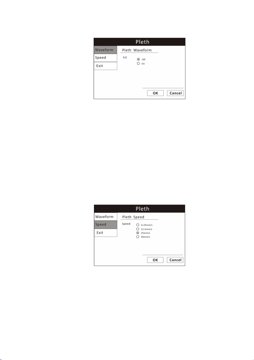
Chapter 8: Oximetry
Figure 8.2: Fill Pleth Waveform
To fill the pleth or not:
1. On the pleth menu, highlight WAVEFROM and push the knob to select.
2. Highlight the desired option (On/ Off)and push the knob to select.
3. Turn the rotary knob to “OK” or “Cancel” to save or delete your settings.
8.6.3 Choose the Waveform Speed
You can choose the speed at which the Pleth is displayed.
Figure 8.3: Choose the Pleth Waveform Speed
To change the speed of the pleth:
1. On the pleth menu, highlight SPEED and push the knob to select.
2. Highlight the desired size of the waveform (6.25, 12.5, 25, or 50 mm/second)
and push the knob to select.
Veterinary Vital Signs Monitor Operation Manual 8-7
Page 76
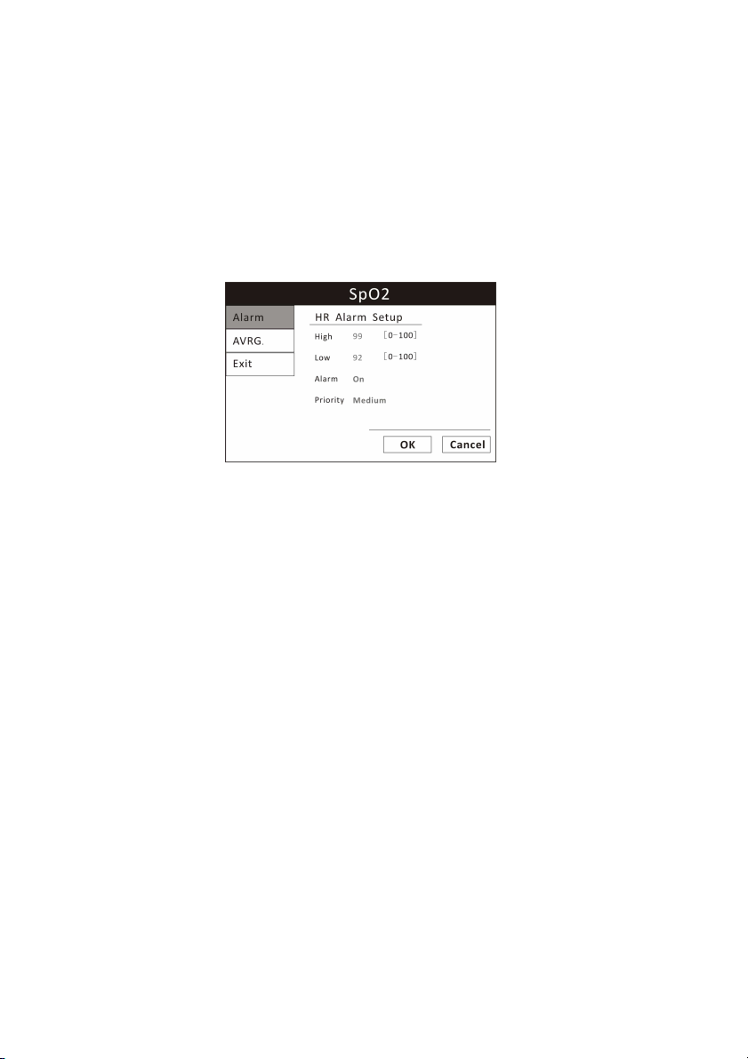
Chapter 8: Oximetry
3. Turn the rotary knob to “OK” or “Cancel” to save or delete your settings.
NOTE!!!! The ECG waveform speed will be changed corresponding with the
pleth speed.
8.7 Adjusting the Settings in the Parameter Box
8.7.1 SpO2 Alarm Setup
Figure 8.4: SpO2 Alarm Setup
1. Turn Alarm Detection On or Off
You can turn on or off the alarm detection capability for the oxygen saturation
value. If SpO2 ALARM is on, an alarm will be issued when the high or low
alarm limit is violated. If you turn SpO2 ALARM off and the high or low alarm
limit is violated, an alarm will not be issued. When you turn off the monitor
and turn it on again, SpO2 ALARM will be reset to ON; the default setting is
ON.
To turn on or off the SpO2 alarm detection:
a)
Push and Turn the rotary knob on the monitor to move the cursor. Highlight
the SpO2 parameter box and push the knob to access the SpO2 parameter
menu.
b)
Highlight ALARM and push the knob to select.
c)
Choose ON or OFF and push the knob to select.
d)
Turn the rotary knob to “OK” or “Cancel” to save or delete your settings.
2. Set High and Low Alarm Limits
8-8 Veterinary Vital Signs Monitor Operation Manual
Page 77

Chapter 8: Oximetry
a)
Push and Turn the rotary knob on the monitor to move the cursor. Highlight
the SpO2 parameter box and push the knob to access the SpO2 parameter
menu.
b)
Highlight ALARM and push the knob to select.
c)
Move the cursor to High/Low and push the knob to select.
d)
Turn the knob to increase or decrease the number and push it to confirm.
e)
Turn the rotary knob to “OK” or “Cancel” to save or delete your settings.
3. Choose Alarm Priority
a)
Push and Turn the rotary knob on the monitor to move the cursor. Highlight
the SpO2 parameter box and push the knob to access the SpO2 parameter
menu.
b)
Highlight SpO2 ALARM and push the knob to select.
c)
Choose Senior, Junior or Medium and push the knob to select.
d)
Turn the rotary knob to “OK” or “Cancel” to save or delete your settings.
8.7.2 Choose the Averaging Period for the Oximetry Parameter
NOTE! SpO2 averaging to the number of pulse beats over which the SpO2
value is averaged; pulse averaging is the number of seconds over
which the pulse value is averaged.
The measured values for oximetry (%SpO2 and PR) can be determined by
averaging the sensor readings over a selected number of beats or seconds. For
example, if you choose 16 Beats, the measured value displayed for oxygen
saturation (%SpO2) will be the average of the oxygen saturation readings over
sixteen pulse beats; the measured value displayed for pulse rate (PR) will be
the average of the number of pulse beats over sixteen seconds.
Veterinary Vital Signs Monitor Operation Manual 8-9
Page 78
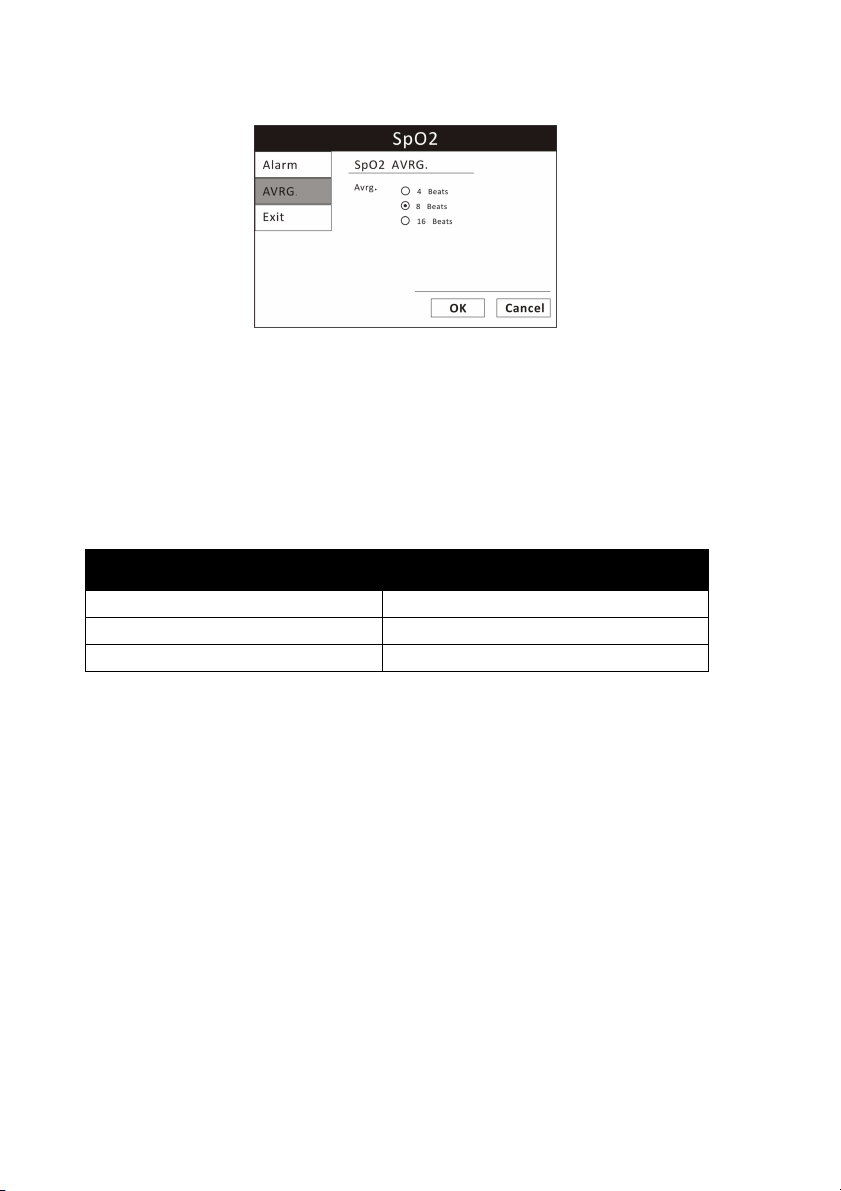
Chapter 8: Oximetry
AVERAGING PERIOD FOR %SPO2
READINGS
AVERAGING PERIOD FOR PR
READINGS
4 beats
4 seconds
8 beats
8 seconds
16 beats
16 seconds
Figure 8.5: Choose SpO2 Average Period
To choose the averaging period:
1. Highlight AVRG. and push the knob to select.
2. Choose the desired averaging period (4 beats, 8 beats, 16 beats) and push
the knob to select.
3. Turn the rotary knob to “OK” or “Cancel” to save or delete your settings.
8-10 Veterinary Vital Signs Monitor Operation Manual
Page 79

Chapter 9: Non-invasive Blood Pressure
Chapter 9: Non-invasive Blood Pressure
9.1 Non-invasive Blood Pressure Measurement Capability
The non-invasive blood pressure (NIBP) parameter provides systolic, diastolic,
and mean arterial blood pressure values. The measured values for
non-invasive blood pressure (SYS, DIA, and MAP) are displayed in the NIBP
parameter box. The measured values will be saved every 10 seconds. NIBP
measurements can be made in automatic, manual, or STAT modes.
9.2 Non-invasive Blood Pressure Warnings, Cautions, and Notes
WARNING! Blood pressure measurements may be inaccurate if cuffs
and/or hoses other than those specified by Utech Co., Ltd. are
used.
WARNING! Verify cuff size is correct for the selected patient mode on the
monitor.
WARNING! Repeated use of STAT mode for periods longer than 15 minutes
should be avoided to reduce the patient's risk for soft tissue or
nerve damage. When using the monitor for long periods of
time, select the longest clinically appropriate measurement
interval and periodically examine the patient for signs of injury
and ensure proper cuff placement.
WARNING! Make sure that hoses are not kinked, compressed, or
restricted.
WARNING! Check that operation of the equipment does not impair the
circulation of the monitored patient.
WARNING! Blood pressure measurements may not be accurate for
patients experiencing arrhythmias.
WARNING! Do not verify the Non-Invasive Blood Pressure calibration while
the cuff is attached to a patient.
CAUTION! Extremity and cuff motion should be minimized during blood
pressure determinations.
Veterinary Vital Signs Monitor Operation Manual 9-1
Page 80

Chapter 9: Non-invasive Blood Pressure
CAUTION! Proper blood pressure cuff size and placement are essential to
the accuracy of the blood pressure determination.
CAUTION! Any blood pressure recording can be affected by the position of
the patient, his or her physiologic condition, and other factors.
CAUTION! Blood pressure measurements should be interpreted by a
physician.
NOTE! There are no user-serviceable adjustments for the Non-Invasive
Blood Pressure calibration verification. If the monitor appears to
be out of calibration, contact your authorized repair center for
help.
NOTE! Systolic and diastolic blood pressure measurements determined
with this device are equivalent to those obtained by the trained
observer using the cuff/stethoscope auscultation method, within
the limits prescribed by the Chinese National Standard, Electronic
or Automated Sphygmomanometers.
NOTE! Mean arterial blood pressure measurements determined with this
device are equivalent to those obtained by an intra-arterial blood
pressure measurement device as determined by Utech Co., Ltd.
9.3 NIBP Theory of Operation
The Vital Signs Monitor uses oscillometric principles to calculate the systolic,
diastolic and mean arterial pressure values from the blood pressure cuff.
When the blood pressure cuff is inflated it creates an occlusion of the artery
on the limb being used. The cuff is then deflated by a set amount of pressure
in the cuff. When an oscillometric pulse is identified, another similar pulse
must also be identified and measured before it steps down again. This method
of measuring blood pressure ensures the measurement is a true measurement
and not a change in the cuff due to motion. If the measurement is not
reproduced a second time, it is not recorded and the pressure is stepped
down. Once two identical oscillations are obtained the cuff deflates. In other
words, it will only capture readings that are reproduced; if there are no similar
oscillations at that pressure, the reading is discarded as artifact. This type of
oscillometric technology is more motion tolerant and generally produces a
higher success rate than other NIBP technologies.
9-2 Veterinary Vital Signs Monitor Operation Manual
Page 81

Chapter 9: Non-invasive Blood Pressure
LIMB CIRCUMFERENCE
CUFF
3-9cm
Extra small
5-15cm
Small
9-25cm
Medium
17-41cm Large
9.4 Measurement Limitations
Measurements are impossible with heart rate extremes of less than 40 bpm or
greater than 300 bpm, or if the patient is on a heart-lung machine.
The measurement may be inaccurate or impossible:
• if a regular arterial pressure pulse is hard to detect
• with cardiac arrhythmias
• with excessive and continuous patient movement such as shivering or
convulsions
• with rapid blood pressure changes
• with severe shock or hypothermia that reduces blood flow to the peripheries
• with obesity, where a thick layer of fat surrounding a limb dampens the
oscillations coming from the artery
• on an edematous extremity.
9.5 Attaching the Patient
1. Choose a blood pressure cuff appropriate for the patient and the limb size
by measuring the circumference of the limb. See the table below.
WARNING! Blood pressure measurements may be inaccurate if cuffs
and/or hoses other than those specified by Utech Co., Ltd. are
used.
NOTE! The NIBP Cuff Kit is latex-free.
Veterinary Vital Signs Monitor Operation Manual 9-3
Page 82
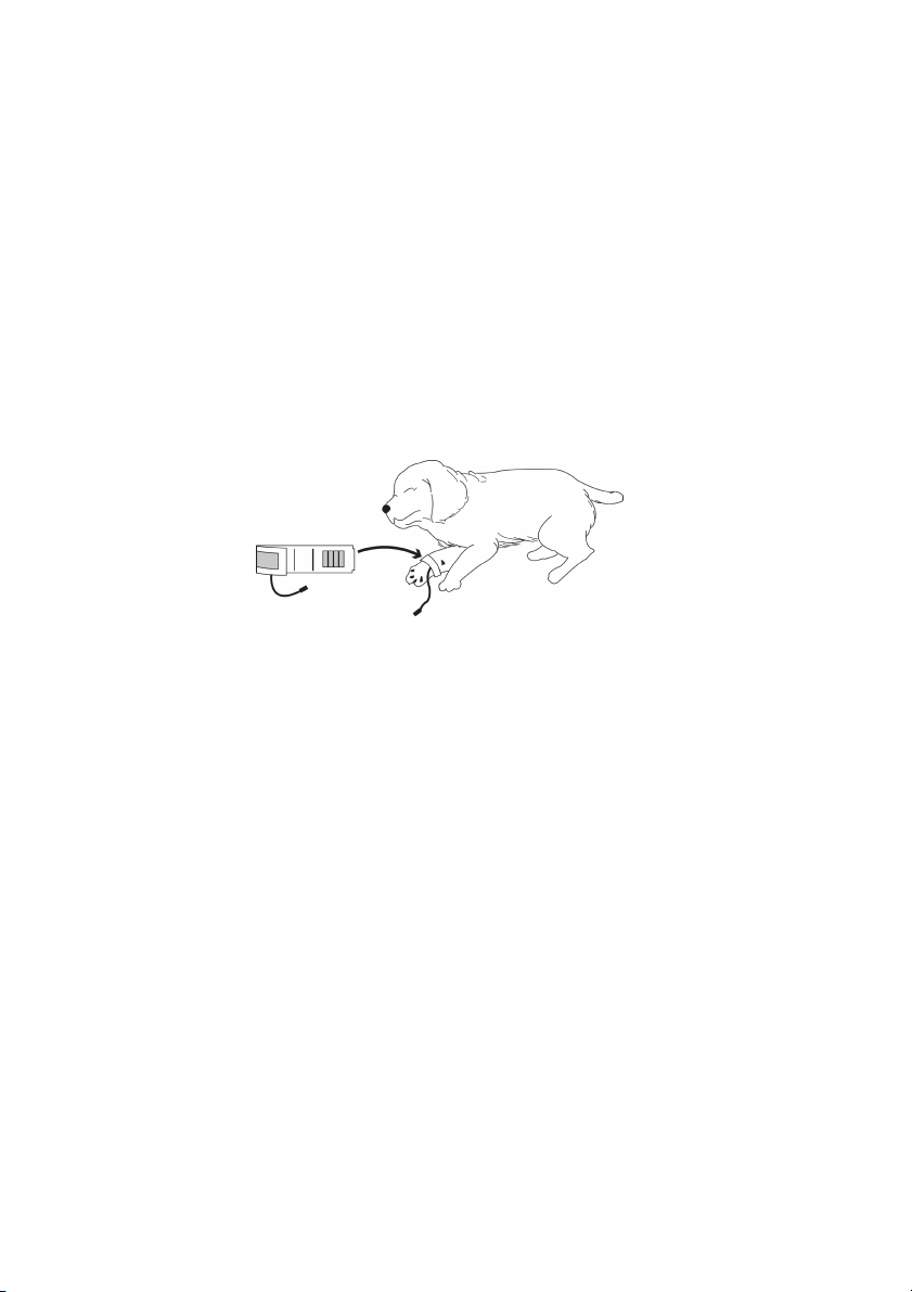
Chapter 9: Non-invasive Blood Pressure
CAUTION! Extremity and cuff motion should be minimized during blood
pressure determinations.
CAUTION! Proper blood pressure cuff size and placement are essential to
the accuracy of the blood pressure determination.
CAUTION! Any blood pressure recording can be affected by the position of
the patient, his or her physiologic condition, and other factors.
WARNING! Verify cuff size is correct for the selected patient mode on the
monitor.
2. Attach the cuff to the patient.
Figure 9.1: Attach NIBP Cuff
a)
Squeeze all the air out of the cuff.
b)
Place the cuff on a limb at the same level as the heart. The cuff logo should
be facing up, away from the patient. The width of the cuff should be
approximately 30-60% of the circumference of the limb. You do not need to
align the cuff along an artery.
c)
Wrap the cuff around the limb and secure the Hook & Loop closure.
CAUTION!!!! The limb used for measurement should be at the same level with
the heart. If this can not be achieved, use the following
correction methods:
■ If the blood pressure cuff is above the heart level, add 0.9mmHg (0.10kPa)
to the displayed value per centimeter, or 2.2mmHg (0.25kPa) per inch.
■ If the blood pressure cuff is below the heart level, subtract 0.9mmHg
(0.10kPa) from the displayed value per centimeter, or 2.2mmHg (0.25kPa)
per inch.
9-4 Veterinary Vital Signs Monitor Operation Manual
Page 83
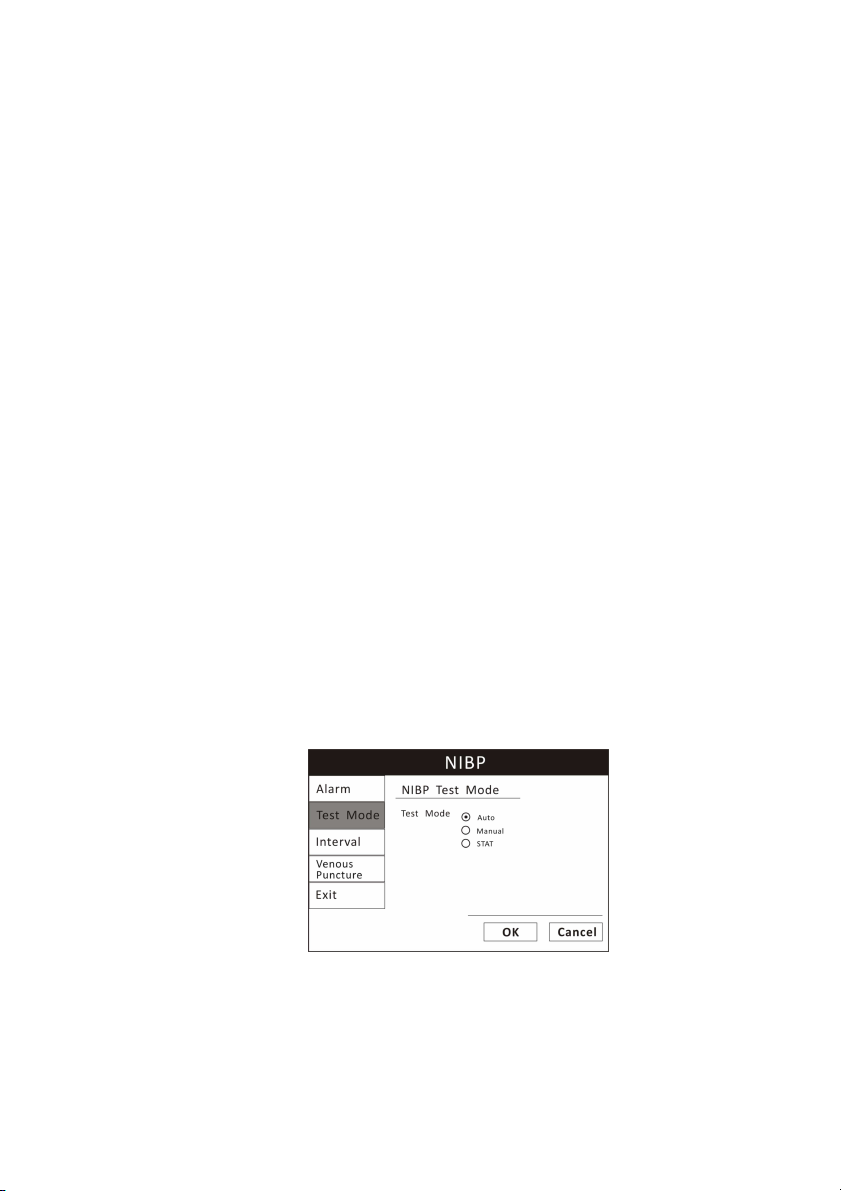
Chapter 9: Non-invasive Blood Pressure
■ If there are doubts regarding the accuracy of the reading, check the
patient’s vital signs using other means before checking the functions of the
monitor.
3. Connect the NIBP supply hose to the monitor.
WARNING! Make sure that hoses are not kinked, compressed, or restricted.
4. Connect the cuff to the supply hose.
The NIBP parameter box is always displayed; measured values will appear as
soon as a blood pressure measurement is taken.
5. Be sure the patient type (Cat, dog, or horse) is appropriate for the patient.
6. If necessary, add the patient information to the monitor.
7. Choose the NIBP mode (AUTO, MANUAL, or STAT) that is appropriate for the
patient.
•Non-invasive blood pressure (NIBP) measurements can be made in automatic,
manual, or STAT modes. In the automatic mode, the monitor will measure the
patient's NIBP periodically, according to the interval you select using the
parameter box menu. In the manual mode, the monitor will measure the
patient's NIBP only when you press the NIBP key. In the STAT mode, the
monitor will measure the patient's NIBP continuously for five minutes. The
default setting for NIBP mode is MANUAL.
Figure 9.2: Choose NIBP Mode
To change the NIBP mode:
1. Push and turn the rotary knob on the monitor to move the cursor. Highlight
NIBP parameter box and push the knob to select.
Veterinary Vital Signs Monitor Operation Manual 9-5
Page 84
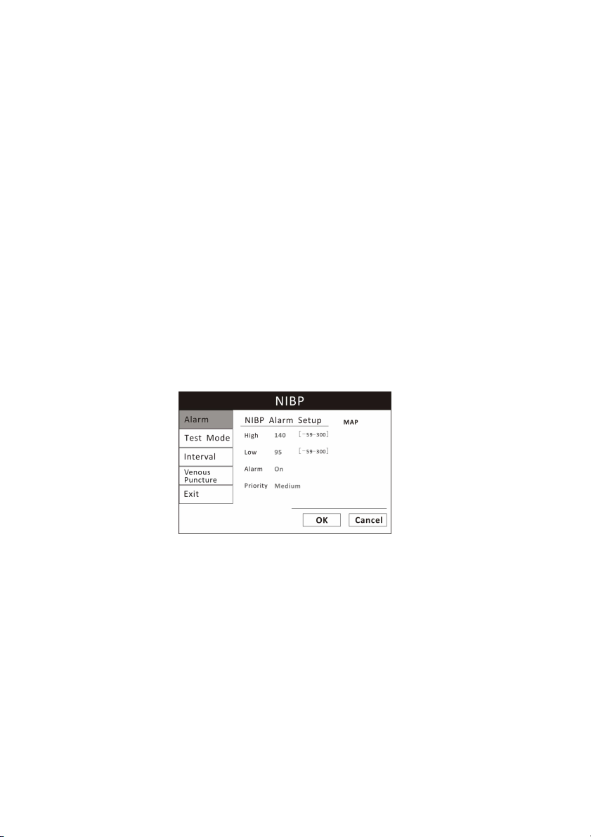
Chapter 9: Non-invasive Blood Pressure
2. Turn the rotary knob to choose a test mode (AUTO, MANUAL, or STAT), and
push the knob to select.
•If you choose AUTO or STAT, the selected mode will be displayed in the
parameter box.
9.6 Adjusting the Settings in the Parameter Box
9.6.1 NIBP Alarm Setup
1. Turn Alarm Detection On or Off
You can turn on or off the alarm detection capability for each of the NIBP
measured values (SYS, DIA, and MAP). If SYS ALARMS is on, an alarm will be
issued when the high or low alarm limit for systolic pressure is violated,
regardless of which set of alarm limits is displayed. If you turn SYS ALARMS off
and the high or low alarm limit is violated, an alarm will not be issued. When
you turn off the monitor and turn it on again, [SYS, DIA, or MAP] ALARMS will
be reset to ON; the default setting for each pressure value is ON.
Figure 9.3: NIBP Alarm Setup
To turn on or off the alarm detection for each pressure value (SYS, DIA and
MAP):
a)
Push and Turn the rotary knob on the monitor to move the cursor. Highlight
the NIBP parameter box and push the knob to access the NIBP parameter
menu.
b)
Highlight NIBP ALARM and push the knob to access the alarms submenu.
c)
Choose each pressure value (SYS, DIA, and MAP) and choose ON or OFF for
each one. Push the knob to select.
9-6 Veterinary Vital Signs Monitor Operation Manual
Page 85
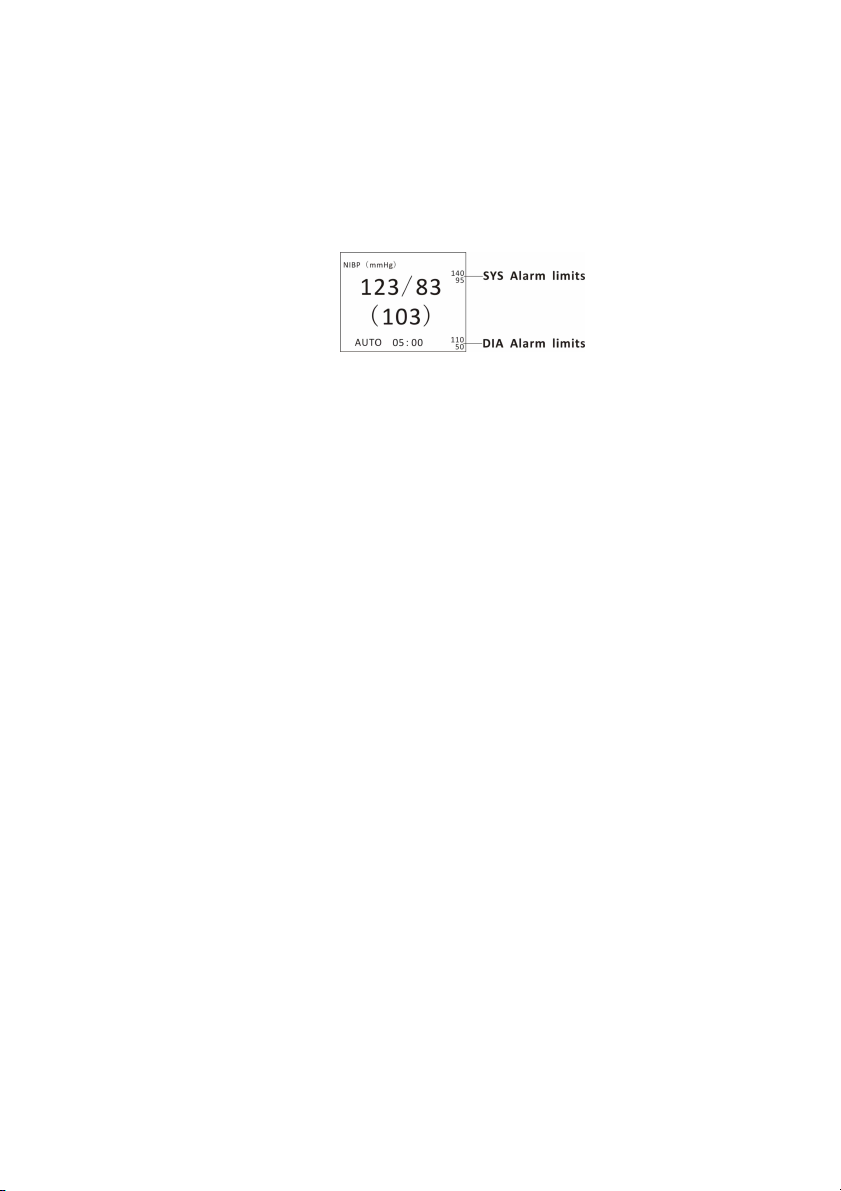
Chapter 9: Non-invasive Blood Pressure
d)
Turn the rotary knob to “OK” or “Cancel” to save or delete your settings.
2. Set High and Low Alarm Limits
The alarm limits displayed in the parameter box are the high and low alarm
limits for SYS and DIA.
Figure 9.4: SYS and DIA Alarm Limits
a)
Push and Turn the rotary knob on the monitor to move the cursor. Highlight
the NIBP parameter box and push the knob to access the NIBP parameter
menu.
b)
Highlight ALARM and push the knob to select.
c)
Choose each pressure value (SYS, DIA, and MAP) and move the cursor to
High/Low and push the knob to select.
d)
Turn the knob to increase or decrease the number and push it to confirm.
e)
Turn the rotary knob to “OK” or “Cancel” to save or delete your settings.
3. Choose Alarm Priority
a)
Push and Turn the rotary knob on the monitor to move the cursor. Highlight
the NIBP parameter box and push the knob to access the NIBP parameter
menu.
b)
Highlight ALARM and push the knob to select.
c)
Choose Senior, Junior or Medium and push the knob to select.
d)
Turn the rotary knob to “OK” or “Cancel” to save or delete your settings.
9.6.2 Choose the Interval for Automatic NIBP Measurements
If you selected the automatic mode (AUTO) for NIBP measurements (instead
of MANUAL or STAT), the monitor will measure the patient's NIBP periodically,
Veterinary Vital Signs Monitor Operation Manual 9-7
Page 86
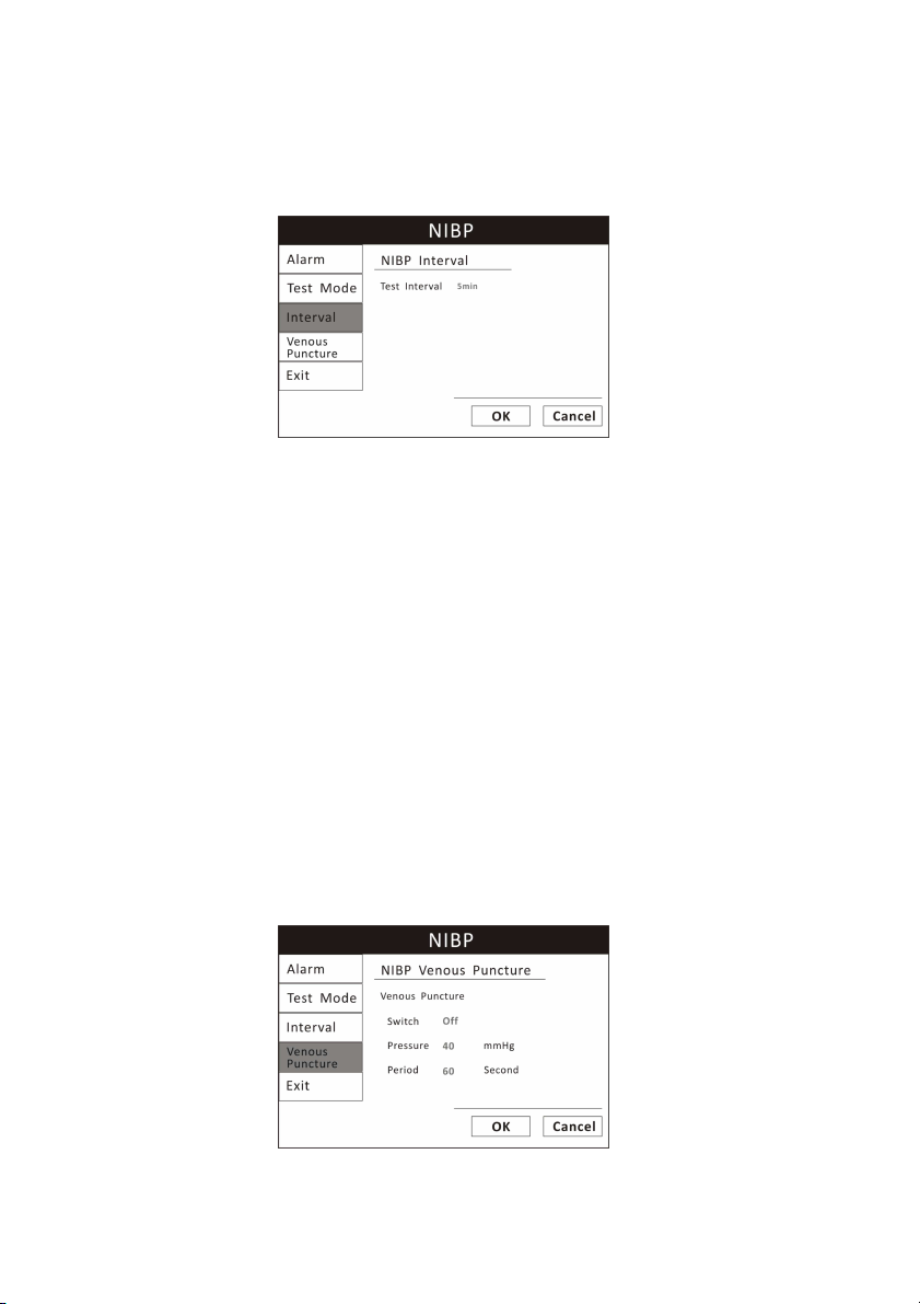
Chapter 9: Non-invasive Blood Pressure
according to the interval you select (2, 3, 5, 10, or 30 minutes, or 1, 2 hours).
The time remaining until the next measurement will be displayed in the
parameter box.
Figure 9.5: Choose NIBP Interval
To choose the automatic NIBP measurement interval:
1. Be sure the NIBP MODE is set to AUTO.
2. On the NIBP parameter menu, highlight INTERVAL and push the knob to
select.
3. Highlight the desired interval (2, 3, 5, 10, or 30 minutes, or 1, 2 hours) and
push the knob to select.
4. Turn the rotary knob to “OK” or “Cancel” to save or delete your settings.
9.6.3 Assist Venous Puncture
You can use the NIBP cuff to cause sub-diastolic pressure. The cuff deflates
automatically after a set time if you do not deflate it.
Figure 9.6: Venous Puncture
9-8 Veterinary Vital Signs Monitor Operation Manual
Page 87

Chapter 9: Non-invasive Blood Pressure
1. In the NIBP parameter menu select Venous Puncture.
2. Puncture vein and draw blood sample.
3. Reselect Venous Puncture to deflate the cuff.
During measurement, the NBP display shows the inflation pressure of the cuff
and the remaining time in venous puncture mode.
9.7 Measuring Non-invasive Blood Pressure (NIBP)
9.7.1 Manual NIBP Mode
If you selected MANUAL as the NIBP mode, press the NIBP key on the monitor.
If the measurement is successful, you will see the systolic, diastolic, and mean
arterial pressure values displayed in the NIBP parameter box.
If the measurement is not successful, you will see dashes (- - -) displayed in the
place of the pressure values. You will see a message displayed in the NIBP
parameter box.
9.7.2 Auto NIBP Mode
If you selected AUTO as the NIBP MODE, the first measurement will begin
after the interval time has elapsed.
If the measurement is successful, you will see the systolic, diastolic, and mean
arterial pressure values displayed in the NIBP parameter box. The automatic
measurement interval will be reset, and another measurement will begin as
soon as the interval time has elapsed.
If the measurement is not successful, you will see dashes (- - -) displayed in the
place of the pressure values. You will see a message displayed in the NIBP
parameter box. The automatic measurement interval will be reset.
9.7.3 STAT NIBP Mode
If you selected STAT as the NIBP MODE, the first measurement will begin
immediately and a five-minute timer is started. NIBP measurements are taken
repeatedly until the five minutes have elapsed.
Veterinary Vital Signs Monitor Operation Manual 9-9
Page 88

Chapter 9: Non-invasive Blood Pressure
If the measurement is successful, you will see the systolic, diastolic, and mean
arterial pressure values displayed in the NIBP parameter box and you will hear
the completion beep. The time of the successful reading will also be displayed
in the parameter box. When the five minutes have passed or if you press NIBP
key to cancel, the mode will automatically return to the previous setting
(MANUAL or AUTO).
If the measurement is not successful, you will see dashes (- - -) displayed in the
place of the pressure values. You will see a message displayed in the NIBP
parameter box. NIBP readings will not continue until the error message is
acknowledged, but the five-minute timer will continue to run.
9.7.4 Canceling the an NIBP Measurement
Regardless the selected mode (AUTO, MANUAL, or STAT), you can stop a
measurement in progress by pressing the NIBP key on the monitor.
If the monitor is in automatic (AUTO) mode, another measurement will start
after the selected interval has elapsed.
If the monitor is in STAT mode and you press the NIBP key to cancel the
measurement, the mode will automatically return to the previous setting
(MANUAL or AUTO).
9.8 Cleaning the NIBP Cuff
1. Place the Cuff Cap on the end of the cuff hose.
NOTE! Failure to place the cuff cap on the hose will allow water to enter
the bladder. This will cause the cuff to malfunction and will
damage the monitor.
2. Pre-clean the cuff by removing contaminate material, hair, and debris.
3. Wash the cuff in a regular load of laundry, or hand-wash.
4. Allow the cuff to air-dry.
CAUTION! Do not place the cuff in the dryer.
9-10 Veterinary Vital Signs Monitor Operation Manual
Page 89

Chapter 10: Respiration Rate
Chapter 10: Respiration Rate (Resp)
10.1 Respiration Rate Measurement Capability
The RESP parameter provides respiration rate (RPM) values. The measured
value for RESP is displayed in the RR parameter box.
For the respiratory measurement (Resp), the monitor measures the thoracic
impedance between two ECG electrodes on the patient’s chest. Changes in the
impedance due to thoracic movement produce the Resp waveform on the
monitor screen. The monitor counts the waveform cycles to calculate the
respiration rate (RR).
10.2 Respiration Rate Warnings, Cautions, and Notes
WARNING! Respiration monitoring is not recommended on active patients.
It may lead to false alarm.
WARNING! Install white and red electrodes in opposite positions to obtain
optimum respiration waveform. Avoid placing the cable above
liver and ventricle to reduce false readings produced by the
heart coverage or pulsation blood flow. This is very important
for neonates.
10.3 Attaching to the Patient
Correct patient skin preparation techniques for electrode placement are
important for Resp measurement: you will find this information in the chapter
on ECG.
The Resp measurement uses the standard ECG cable sets and lead placements.
You can use any of the different types of ECG cable sets to measure Resp, as
long as you use ICU ECG cables.
The Resp signal is always measured between two of the ECG electrodes. If you
are using standard ECG electrode placement, Resp is measured between the
RA and LL electrodes.
10.4 Choosing the Waveform Settings
10.4.1 Change the ECG Lead
Veterinary Vital Signs Monitor Operation Manual 10-1
Page 90
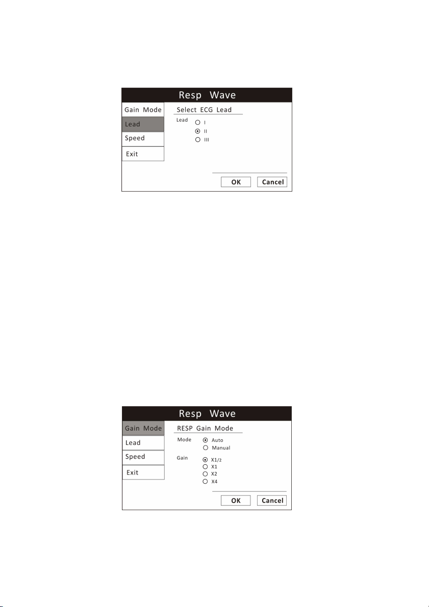
Chapter 10: Respiration Rate
You can choose one of the ECG lead as a source to measure the RR from lead I,
II, III. The selected lead will be displayed in the waveform channel.
Figure 10.1: Select ECG Lead
To change the ECG lead:
1. On the RESP waveform menu, highlight LEAD and push the knob to access
the submenu.
2. Highlight the desired ECG lead and push the knob to select.
3. Turn the rotary knob to “OK” or “Cancel” to save or delete your settings.
10.4.2 Choose the Waveform Size
If any of the displayed RESP waves is too small or clipped, you can change the
size of the RESP waveforms on the display. The selected size (X1/2, X1, X2, or
X4) will appear in the waveform channel. The default size is times one (X1).
Figure 10.2: Choose RESP Waveform Size
To change the size of the RESP waveform:
10-2 Veterinary Vital Signs Monitor Operation Manual
Page 91
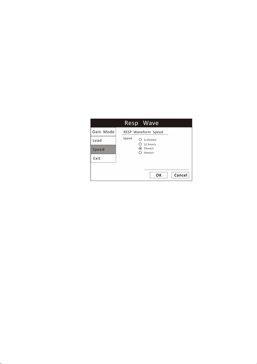
Chapter 10: Respiration Rate
1. On the RESP waveform menu, highlight Gain Mode and push the knob to
select.
2. Highlight the desired size of the waveform (X1/2, X1, X2, or X4) and push
the knob to select.
3. Turn the rotary knob to “OK” or “Cancel” to save or delete your settings.
10.4.3 Choose the Waveform Speed
You can choose the speed at which the RESP waveform is updated.
Figure 10.3: Choose RESP Waveform Speed
To change the speed of the RESP Waveform:
1. On the RESP Wave menu, highlight SPEED and push the knob to select.
2. Highlight the desired size of the waveform (6.25, 12.5, 25, or 50 mm/second)
and push the knob to select.
3. Turn the rotary knob to “OK” or “Cancel” to save or delete your settings.
10.5 Adjusting the Settings in the Parameter Box
10.5.1 RR Alarm Setup
Veterinary Vital Signs Monitor Operation Manual 10-3
Page 92
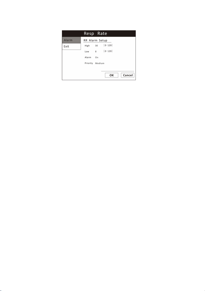
Chapter 10: Respiration Rate
Figure 10.4: RR Alarm Setup
1. Turn Alarm Detection On or Off
You can turn on or off the alarm detection capability for the Resp rate value. If
RR ALARMS is on, an alarm will be issued when the high or low alarm limit is
violated. If you turn RR ALARMS off and the high or low alarm limit is violated,
an alarm will not be issued. When you turn off the monitor and turn it on
again, RR ALARMS will be reset to ON; the default setting is ON.
To turn on or off the Resp rate alarm detection:
a)
Push and turn the rotary knob on the monitor to move the cursor. Highlight
the HR parameter box and push the knob to access the RR parameter menu.
b)
Highlight RR ALARM and push the knob to select.
c)
Choose ON or OFF and push the knob to select.
d)
Turn the rotary knob to “OK” or “Cancel” to save or delete your settings.
2. Set High and Low Alarm Limits
a)
Push and Turn the rotary knob on the monitor to move the cursor. Highlight
the RR parameter box and push the knob to access the RR parameter menu.
b)
Highlight RR ALARM and push the knob to select.
c)
Move the cursor to High/Low and push the knob to select.
d)
Turn the knob to increase or decrease the number and push it to confirm.
10-4 Veterinary Vital Signs Monitor Operation Manual
Page 93

Chapter 10: Respiration Rate
e)
Turn the rotary knob to “OK” or “Cancel” to save or delete your settings.
3. Choose Alarm Priority
a)
Push and Turn the rotary knob on the monitor to move the cursor. Highlight
the RR parameter box and push the knob to access the RR parameter menu.
b)
Highlight RR ALARM and push the knob to select.
c)
Choose Senior, Junior or Medium and push the knob to select.
d)
Turn the rotary knob to “OK” or “Cancel” to save or delete your settings.
Veterinary Vital Signs Monitor Operation Manual 10-5
Page 94

Chapter 10: Respiration Rate
This Page is Intentionally Left Blank!
10-6 Veterinary Vital Signs Monitor Operation Manual
Page 95

Chapter 11: Temperature
Chapter 11: Temperature
11.1 Temperature Measurement Capability
Two independent channels of temperature (T1 and T2) monitoring are
available. Each channel is compatible with Smiths Medical PM, Inc. YSI
400-series disposable temperature sensors, or equivalent. The measured
value for each temperature channel (T1 and T2) is displayed in the TEMP
parameter box. If the temperature channel is turned on and no measured
value is available, dashes (- - -.-) will be displayed in the parameter box.
11.2 Temperature Warnings, Cautions, and Notes
WARNING! Before monitoring starts, check if the sensor cable is properly
connected. Pull the temperature sensor cable from the channel
1 jack, an error message “T1 sensor is off” is displayed on the
screen and the alarm sound can be heard. The same happens
with the other channel.
WARNING! Be cautious when handling temperature sensors and cables.
When it is not in use, the sensor and cable ought to be in a
loose loop. Tightly folded cable can cause mechanical damage.
WARNING! Temperature calibration should be done once a year (or
according to the schedule specified in the hospital procedure).
If calibration is needed, contact the manufacturer.
WARNING! Disposable temperature sensors should only be used once.
WARNING! During monitoring process, the temperature measurement
instrument will conduct a self-check every hour lasting for two
seconds. This will not affect normal operation of the monitor.
NOTE! Use only temperature sensors and interface cables specifically
intended for use with this device.
11.3 Attaching the Patient
1. Choose a temperature sensor. Each temperature channel is compatible with
Utech Co., Ltd. YSI 400-series disposable temperature sensors, or equivalent.
Veterinary Vital Signs Monitor Operation Manual 11-1
Page 96
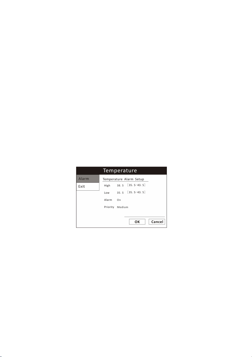
Chapter 11: Temperature
2. Apply the temperature sensor to the patient according to the standards of
practice and care for your facility, and according to the temperature sensor
manufacturer’s instructions.
3. If applicable, connect the temperature sensor to the interface cable.
4. Connect the interface cable and the temperature sensor to the T1 or T2
receptacle on the side of the monitor.
The monitor will automatically detect when the interface cable and
temperature sensor are connected.
The temperature parameter will be active and measured values for
temperature will be displayed in the TEMP parameter box.
11.4 Adjusting the Settings in the Parameter Box
11.4.1 TEMP Alarm Setup
Figure 11-1: TEMP Alarm Setup
1. Turn Alarm Detection On or Off
You can turn on or off the alarm detection capability for temperature value. If
ALARMS is on, an alarm will be issued when the high or low alarm limit for
either channel 1 or 2 is violated. If you turn ALARMS off and the high or low
alarm limit for either channel 1 or 2 is violated, an alarm will not be issued.
When you turn off the monitor and turn it on again, the ALARMS will be reset
to ON; the default setting for each is ON.
To turn on or off the TEMP alarm detection:
11-2 Veterinary Vital Signs Monitor Operation Manual
Page 97

Chapter 11: Temperature
a)
Push and Turn the rotary knob on the monitor to move the cursor. Highlight
the TEMP parameter box and push the knob to access the TEMP parameter
menu.
b)
Highlight ALARM and push the knob to select.
c)
Choose ON or OFF and push the knob to select.
d)
Turn the rotary knob to “OK” or “Cancel” to save or delete your settings.
2. Set High and Low Alarm Limits
a)
Push and Turn the rotary knob on the monitor to move the cursor. Highlight
the TEMP parameter box and push the knob to access the TEMP parameter
menu.
b)
Highlight ALARM and push the knob to select.
c)
Move the cursor to High/Low and push the knob to select.
d)
Turn the knob to increase or decrease the number and push it to confirm.
e)
Turn the rotary knob to “OK” or “Cancel” to save or delete your settings.
3. Choose Alarm Priority
a)
Push and Turn the rotary knob on the monitor to move the cursor. Highlight
the TEMP parameter box and push the knob to access the TEMP parameter
menu.
b)
Highlight TEMP ALARM and push the knob to select.
c)
Choose Senior, Junior or Medium and push the knob to select.
d)
Turn the rotary knob to “OK” or “Cancel” to save or delete your settings.
Veterinary Vital Signs Monitor Operation Manual 11-3
Page 98

Chapter 11: Temperature
This Page is Intentionally Left Blank!
11-4 Veterinary Vital Signs Monitor Operation Manual
Page 99
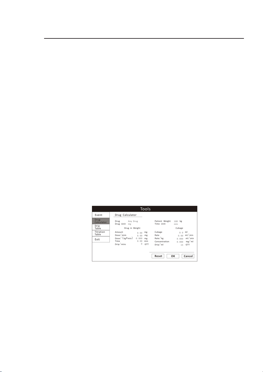
Chapter 12: Drug Calculator
Chapter 12: Drug Calculator
Drug mixtures for intravenous (IV) drug infusions combine information on drug
dose, rate, amount, volume, concentration, and standardized rate. The Drug
Calculator helps you to manage infusions by calculating one of these values at
a time.
Caution! Before you administer any drug, always check that the correct
calculation units and patient category selected. Consult your
pharmacy if you have questions.
Caution! Decisions on the choice and dosage of drugs administered to
patients must always be made by the physician in charge. The
Drug Calculator performs calculations based on the values
input during use, it does not check the plausibility of the
calculations performed.
12.1 Accessing the Drug Calculator
To access the Drug Calculator, Press the Main Menu key and turn the rotary
knob on the monitor to choose the Tools and push the knob to select. And
then move the knob to highlight the Drug Calculator.
Figure12.1 Drug Calculator
12.2 Measurement Units
Drug units
When the drug name is “any drug”, you can select: g, mg, mcg, unit, k unit, m
unit, mEq.
Once the drug name is identified, the unit is set by the drug calculator
automatically. The user cannot modify it.
Veterinary Vital Signs Monitor Operation Manual 12-1
Page 100

Chapter 12: Drug Calculator
After the drug measurement unit is set, the drug weight and concentration
units in the drug calculator adjust accordingly.
Time units
Min (minute) and hr (hour) are used as time units. After setting the time unit,
the dosage rate and infusion rate units in the drug calculator adjust
accordingly.
12.3 Glossary
Drug weight
time period.
Volume
Dose/min
of time (per minute/hour).
Dose/(kg*min)
weight injected in the patient within the unit time period (per minute or hour)
Infusion
within a unit of time (per minute, hour). The unit is ml/min or ml/hr.
Infusion
injected into the patient within unit time (per minute, hour), the unit is ml/min
or ml/hr.
Time
Concentration
Drip/min, Drip/hr
12-2 Veterinary Vital Signs Monitor Operation Manual
: The total weight of the drug used by a patient within a certain
: The liquid volume of the solution including the drug.
or
Dose/hr
: The drug quantity injected into a patient within a unit
or
Dose/(kg*hr)
: The amount of drug per 1kg of a patient’s
Dose/(kg*min)*Patient Weight=Dose/min
Dose/(kg*hr)*Patient Weight=Dose/hr
Rate
: The volume of the drug solution injected into a patient’s body
Rate/kg
: The volume of the drug solution per 1kg of a patient’s weight
Infusion Rate/kg*Patient Weight=Infusion Rate
: The consumed time for drug infusion (the unit is min, hr).
: The concentration of the drug in the solution.
Concentration=Total Drug/Liquid Volume of Solution
: The number of drops (guttae) per unit time (min/hr)
 Loading...