

U-tec Ultraloq UL3 Series Installation Instructions Manual
Ultraloq UL3 Series
Fingerprint and Touchscreen Smart Lock
Installation Instructions ( V1.6)
Welcome

Installation Video
Please watch our easy step by step installation video before attempting to install
your Ultraloq UL3 Series Fingerprint and Touchscreen Smart Lock.
www.u-tec.com/support
If you have questions regarding the installation process, please contact us
at support@u-tec.com
Important Notes
• Do not use a power drill for installation.
• Install and test the lock with the door open to avoid being locked out.
• Please read all the instructions before contacting customer support.
• Please contact customer support before returning the product to the store.
• DO NOT install the batteries before installing the lock!
Follow the instructions in sequential order!
• If you have previously installed this lock on another door, you must perform a
Factory Default Reset FIRST! See the User Guide for more information.
• This lock is designed for the following operating temperatures:
Outside Lock Body (exterior mounted): -31˚F (-35˚C) to 158˚F (70˚C)
Inside Lock Body (interior mounted): 14˚F (-10˚C) to 131˚F (55˚C)
Need Help?
For technical documents and more
Please visit www.u-tec.com/support
Tel: 844-HEY-UTEC (844-439-8832)
Email: support@u-tec.com
- 1 -
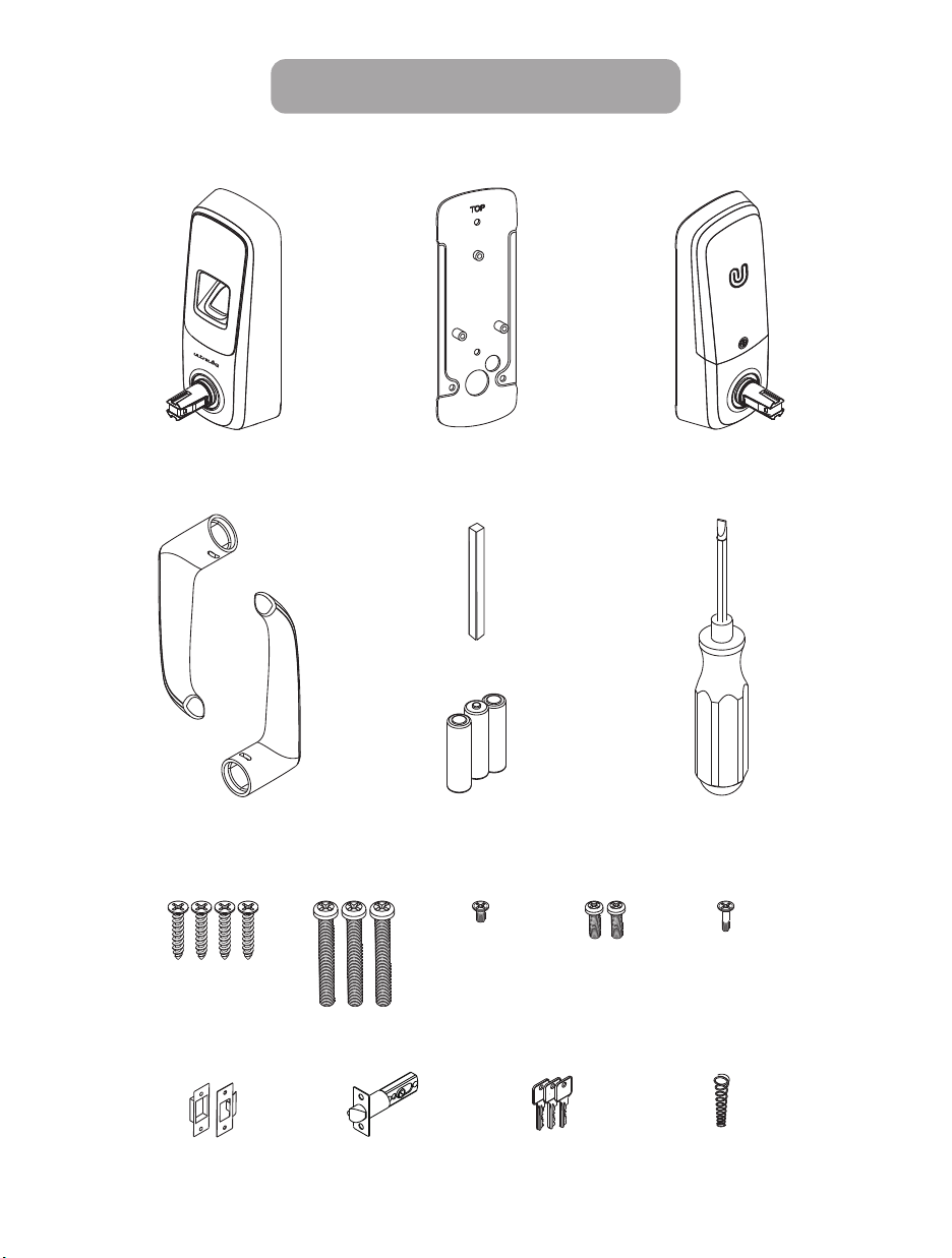
Included in the box
Exterior Assembly Interior AssemblyInterior Mounting Plate
Handle
Screw A Screw B
LatchStrike Backup Keys Spring
Spindle
AA Batteries
AA alkaline
Screw C
Screwdriver
Screw D Screw E
- 2 -
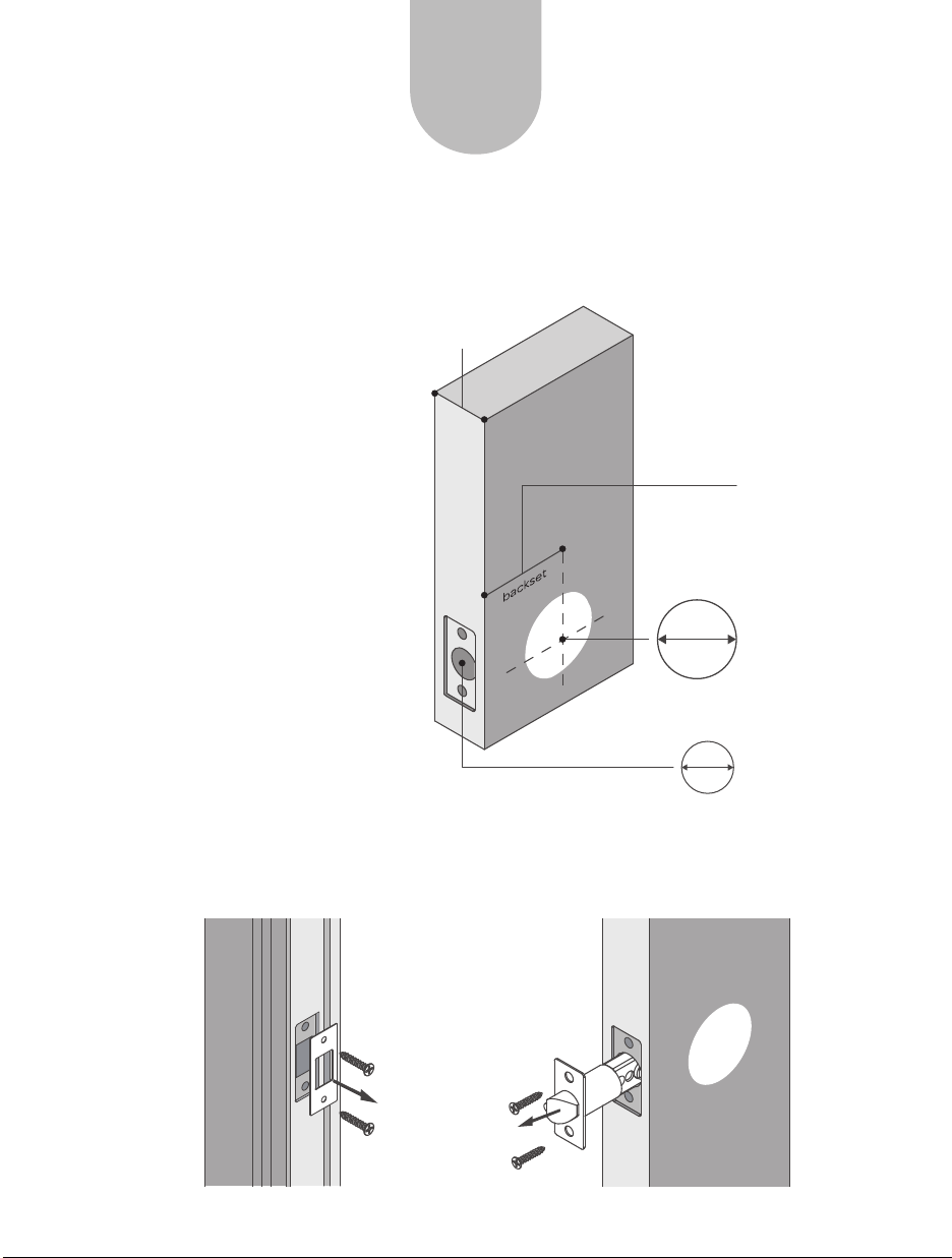
Preparing Door
Check the door’s dimensions.
Step 1:
Measure to confirm that the door
is between (35 mm-44mm) thick.
Step 2:
Measure to confirm that the hole in the
door is
1
1
/
2
”
8
3
3
/
/
~
” 1
”
8
4
(53 mm) .
STEP
1
3
3
/
~
1
” 1
(35 mm-44mm)
8
/
”
4
3
/
(70 mm)
2
”
4
OR
3
/
2
”
(60 mm)
8
Step 3:
Measure to confirm that the backset is
either
3
3
/
/
2
”(60mm-70mm) .2
”~
4
8
Step 4:
Measure to confirm that the hole in
the door edge is 1” (25 mm) .
If you are installing Ultraloq on the door with an existing lock,
please remove the current lock and latch.
1
/
2
8
53 mm
1”
25 mm
”
1
/
2
”(53 mm)
8
1” (25 mm)
- 3 -

STEP
2
Preparing Lock
If your door thickness is over 1.65”(42mm), please install this spring.
Interior
Spring ×1
Before installing the lock on the door
1. Slide the battery cover up and out (note the two tabs at the bottom of the battery cover).
2. Remove the inside mounting plate (with gasket) from the back (door side)
of the interior assembly.
- 4 -
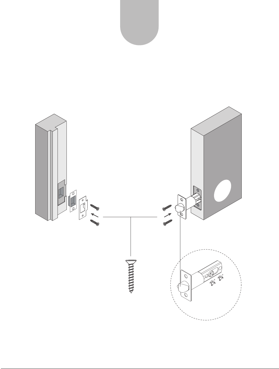
STEP
3
Installing Latch and Strike
1. Install latch on the door. Make sure the latch angle faces door jamb.
2. Install the strike on the door frame, ensuring you allow for the bolt to be
centered in the strike.
Screw A
- 5 -
Angle faces jamb
60~70mm
Adjust the latch
basket length
STEP
4
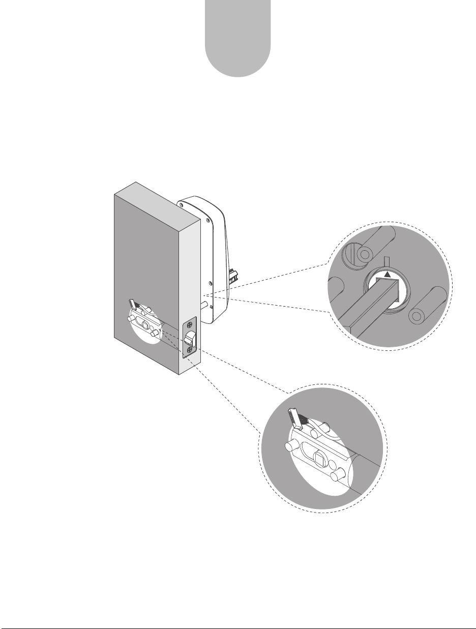
Installing Exterior Assembly
1. Install the exterior assembly.
2. Make sure the triangle is facing upwards as illustrated.
3. Route the cable under bolt and through hole stated below.
- 6 -- 6 -
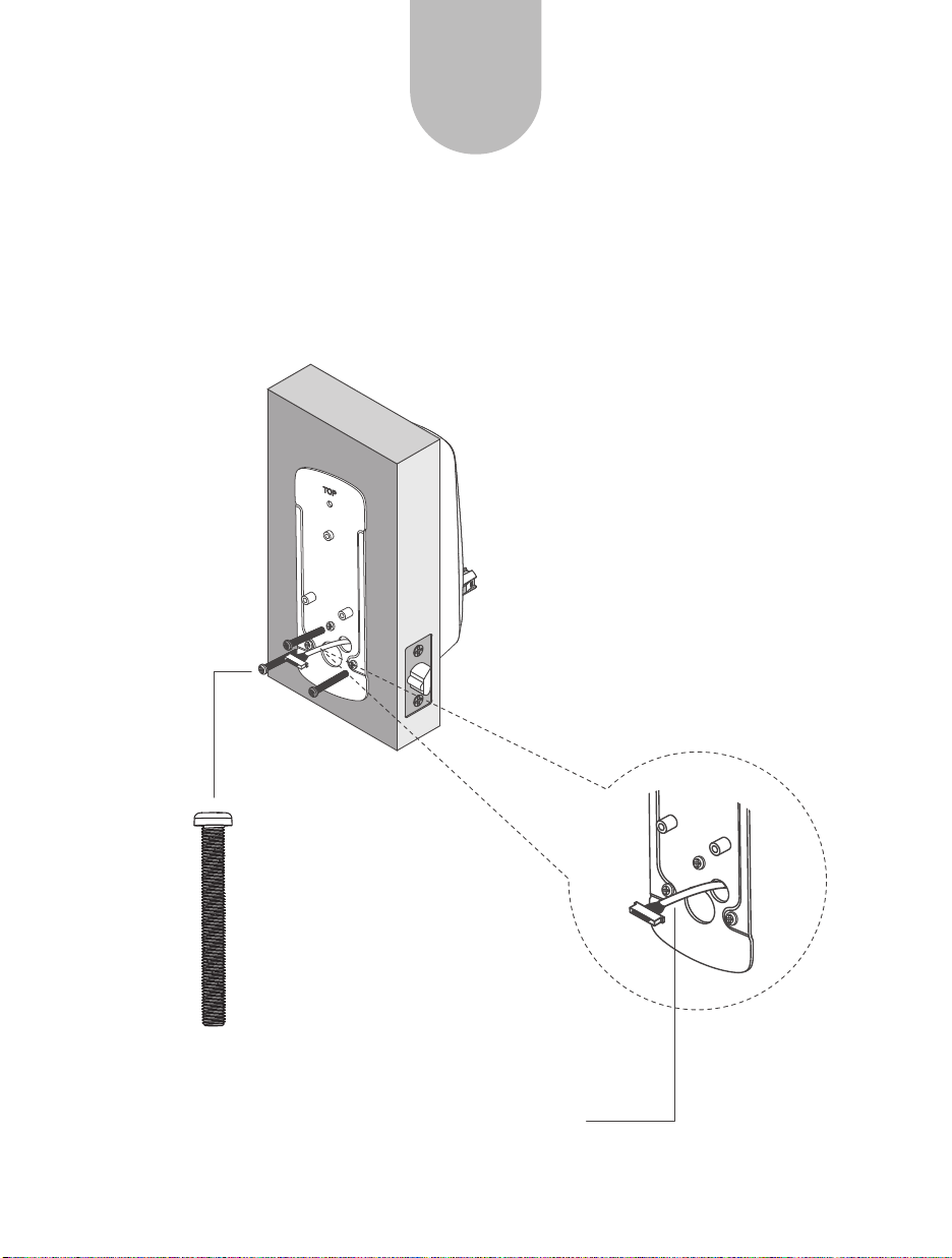
STEP
5
Installing Interior Mounting Plate
1. Install interior mounting plate.
2. Secure it to the exterior assembly using screws B.
Screw B
Route wire over the hole
- 7 -
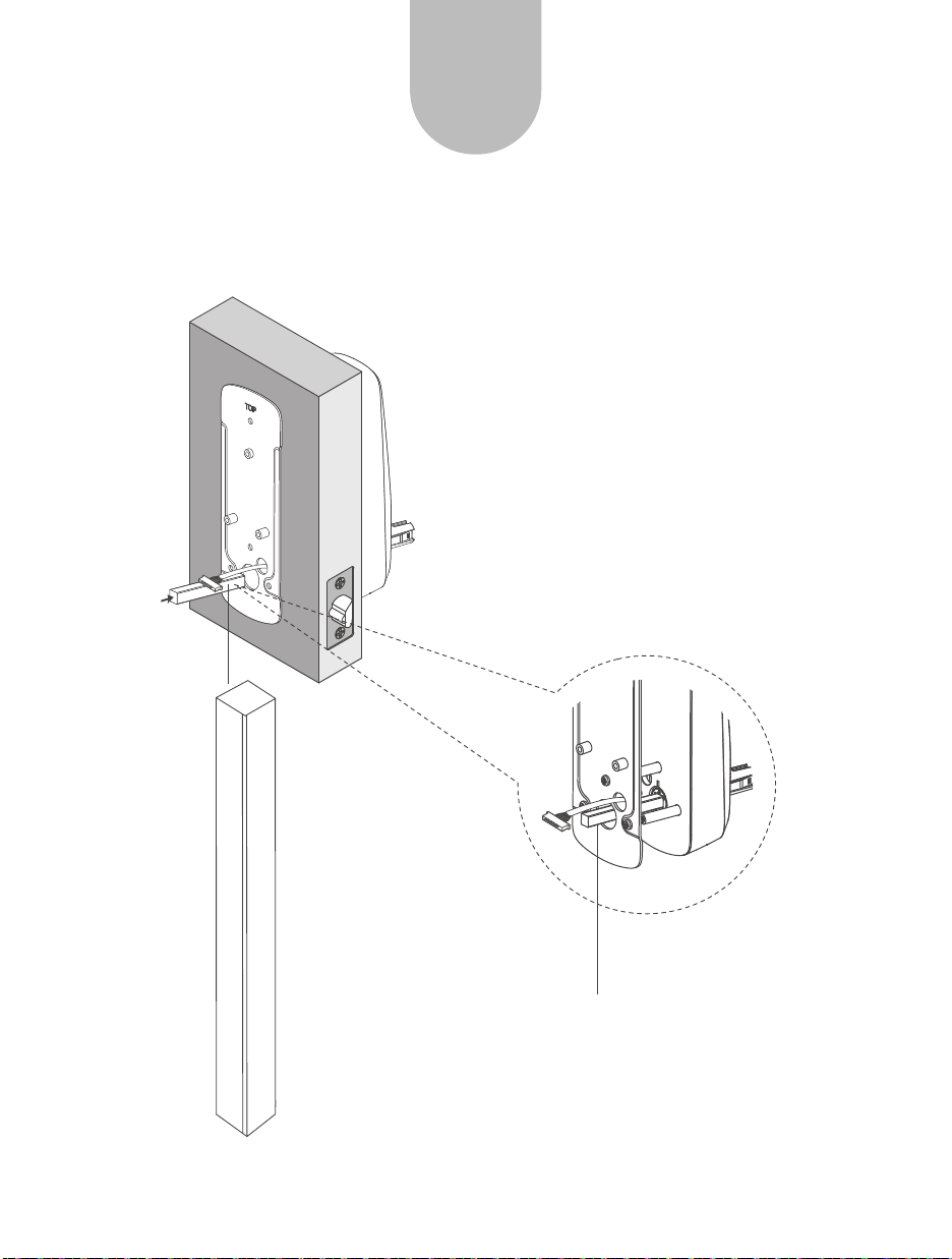
Plug In The Spindle
STEP
6
Spindle
Plug in the spindle
- 8 -
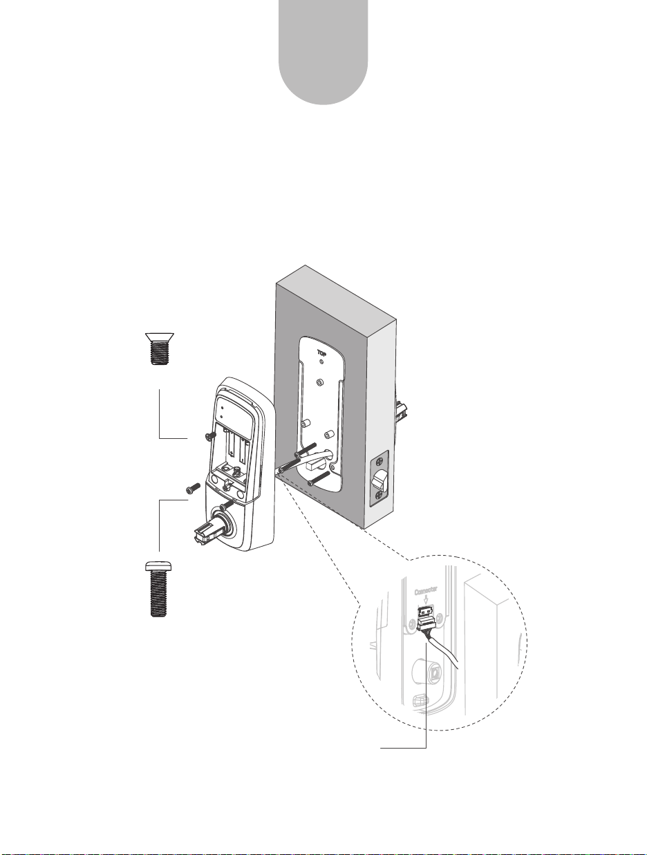
STEP
7
Installing Interior Assembly
1. Attach the cable to the connector on interior assembly by lining up notches on
the cable connector to slots on that connector. Press the connector in firmly
using thumbs until completely seated.
2. Secure interior assembly using screws.
Screw C
Screw D
Connect the cable
- 9 -
 Loading...