

Page 1
Installation Instructions
ON
1 2 3 4 5 6 7 8
Description
The OEM transceiver modules are compatible with GE Security
wireless transmitters. The modules have an onboard receiver,
microprocessor, and connection for a daughter board. The microprocessor controls the receiver, providing antenna switching and
AGC functions. It also analyzes the received data from the
receiver, validates incoming packets, and returns packets to the
receiver when polled. A daughter board, which communicates
with the module via an 8-pin header, can be added to implement
a variety of functions.
Each module encapsulates the receiver functions and formats and
presents a common interface to the daughter board. Therefore,
even though protocols vary among the GE Security radio
frequencies used around the world, the interface is the same to
the daughter board.
Installation guidelines
Observe the following guidelines when installing the OEM transceiver module:
• Allow at least 9 inches (22.9 cm) of clearance above the
enclosure for the antennas.
• Avoid mounting locations that expose the module to moisture.
• Avoid areas with excessive metal or electrical wiring
including furnace and utility rooms. If unavoidable, mount
on or near metal with the antenna extending above the
metallic surfaces as shown in Figure 1.
600-1025 OEM Transceiver Module
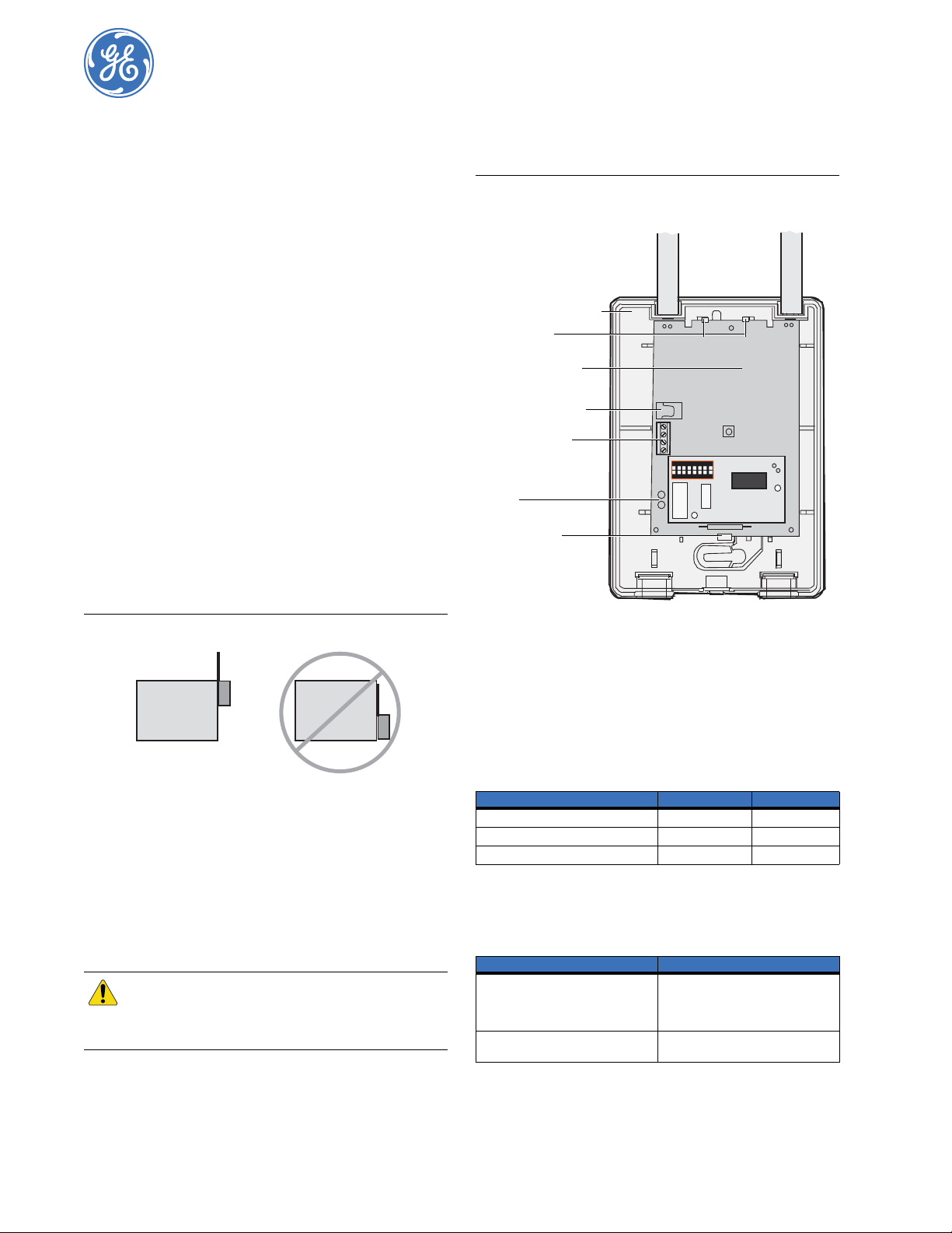
Figure 2. Installing the circuit board
Antenna shrouds
600-1029 enclosure
Top latches
OEM transceiver
2 mm power jack
Terminal block
ON
1 2 3 4 5 6 7 8
LEDs
Bottom latch
466-2226B
May 2005
Figure 1. Mounting on or near metal
Metal
Note: For UL installations this module must be mounted in the 600-
1029 enclosure. Daughter boards have not been investigated
for use by UL.
Metal
Installation
To mount the OEM transceiver m odule onto the back plate of the
600-1029 enclosure, do the following:
1. Insert the antennas into the antenna shrouds (Figure 2).
2. Gently slide the top of the circuit board under the two top
latches.
CAUTION
3. Snap the circuit board in at the bottom latch to secure it in
place as shown in Figure 2.
You must be free of static electricity before
handling circuit boards. Wear a grounding strap
or touch a bare metal surface to discharge static
electricity.
4. Connect DC power to the OEM transceiver module using 2
mm power jacks (center positive) or connect flyleads to the
terminal block as labeled on the board.
Note: For model 600-1025-02-43, the cable length must be less than
3 m (9.8 ft.) for CE compliance.
LED operation
Table 1 shows the LED indications for the OEM transceiver
module.
Table 1. OEM transceiver module LED indications
Indication Green LED Red LED
Powered up On Off
Communication with daughter baord On Flashing
Valid packet received One flash off Off or flashing
Troubleshooting
The following table gives troubleshooting suggestions for the
OEM transceiver module.
Table 2. OEM transceiver module troubleshooting
Problem Action
OEM transceiver module’s green and
red LEDs are off
OEM receiver module’s green LED is
on and the red LED is off
1. Check that the transformer is plugged
in.
2. Check the transformer to module
wiring.
Check the daughter board mounting.
Page 2

600-1025 OEM Transceiver Module
2
Installation Instructions
FCC compliance
This device complies with FCC Rules Part 15. Operation is subject to the following
two conditions:
1. This device may not cause harmful interference.
2. This device must accept any interference that may be received, includi ng interference that may cause undesired operation.
Changes or modifications not expressly approved by GE Security can void the
user’s authoriy to operate the equipment.
Specifications
Models 600-1025-02-95R and 600-1025-02-43
Frequency
600-1025-02-95R
600-1025-02-43
Sensor compatability
600-1025-02-95R
600-1025-02-43
Power required (without
daughter board)
Typical 45mA
Maximum 100mA
Wireless range 1,000 feet (305 m)
Listings
600-1025-02-95R
600-1025-02-43
Operating temperature 32 to 140°F (0 to 60°C)
Storage temperature -30 to 140°F (-34 to 60°C)
Maximum relative humidity 90% noncondensing
Dimensions 3.2 x 4.6 x 0.6 inches (8.1 x 11.7 x 1.5 cm)
Features Antenna tamper, jam detect, wall tamper, cover
Enclosure 600-1029
USB adaptor 59-873
Repeater adaptor 600-1031
Stand-off 40-262
319.5 MHz
433.92 MHz
All 319.5 MHz sensors
All 433 MHz sensors
UL (985 1023), FCC ID (B4Z-875-TCVR), DoC,
IC: 867-875CVR
CE
tamper
CE declaration of conformity
Manufacturer’s name: GE Security
Manufacturer’s address: 1275 Red Fox Road
EU representative: GE Security B.V.
Product indentification: Product: 433 MHz OEM Transceiver
R&TTE directive:
EMC: TUV 0123 / GE Security
Safety: GE Security
Radio: TUV 0123
Equipment class identifier:
(RF products falling under the
scope of R&TTE)
Means of conformity
We declare under our sole responsibility that this product is in conformity with
Directive 93/68/EEC (Marking) and/or complies to the essential requirements and
all other relevant provisions of the 1999/5/EC (R&TTE) based on test results using
(non) harmonized standards in accordance with the Directives mentioned.
Arden Hills, MN 55112
USA
Kelvinstraat 7
6003 DH Weert
The Netherlands
Model number: 600-1025-02-43
Brand: GE Security
Test report reference: CEQP-600-1025-02-43
Applied standards: EN50130-4 (1995) +A1
(1998)
Test report reference: CEQP-600-1025-02-43
Applied standards: EN60950-1:2001
Test report reference: CEQP 600-1025-02-43
Applied standards: EN300220-3 v1.1.1 (09-
2000)
None (class 1 product)
Toll-free: 888.437.3287 (US including Alaska a nd Hawaii; Puero Rico; Canada)
Technical support
Outside the toll-free area: Contact your local dealer.
www.gesecurity.com
 Loading...