

Page 1

OEM Transceiver Module with Crystal
Transmitter Installation Instructions
Introduction
The OEM transceiver modules are compatible with Interlogix
wireless transmitters and receivers. The modules have an
onboard receiver and transmitter, microprocessor, and
connection for a daughter board. The microprocessor
controls the receiver and transmitter, providing antenna
switching and AGC functions. It also analyzes the data from
the receiver, validates incoming packets, and returns
packets to the controlling device when polled. A daughter
board, which communicates with the module via an 8-pin
header, can be added to implement a variety of functions.
Each module encapsulates the receiver and transmitter
functions and formats and presents a common interface to
the daughter board. Therefore, even though protocols vary
among the Interlogix radio frequencies used around the
world, the interface is the same to the daughter board.
Installation Guidelines
Observe the following guidelines when installing the OEM
transceiver module:
Allow at least 9 inches (22.9 cm) of clearance above the
enclosure for the antennas.
Avoid mounting locations that expose the module to
moisture.
Avoid areas with excessive metal or electrical wiring
including furnace and utility rooms. If unavoidable,
mount on or near metal with the antenna extending
above the metallic surfaces as shown in Figure 1.
While a transmitter may have an open-air range of 1000
ft. (300 m) or more, the installation site can have a
significant effect on the transmitter range. Changing the
sensor location may help overcome adverse wireless
conditions.
Installation
600-1029 Enclosure
To mount the 600-1029 enclosure, follow the installation
instructions provided with the enclosure.
600-0131 or 600-1067 Daughter Board
To attach the 600-0131 or 600-1067 daughter board, follow
the installation instructions provided with the daughter board.
600-1046-95 OEM Transceiver Module
To mount the OEM transceiver module onto the back plate
of the 600-1029 enclosure, do the following:
1. Insert the antennas into the antenna shrouds (Figure 2).
Caution: You must be free of static electricity before
handling circuit boards. Wear a grounding strap or
touch a bare metal surface to discharge static
electricity.
2. Gently slide the top of the circuit board under the two
top latches.
3. Snap the circuit board in at the bottom latch to secure it
in place as shown in Figure 2.
Figure 1: Mounting on or near metal
© DDMONYY UTC Fire & Security. All rights reserved. 1 / 3 P/N 466-2236 • REV D • 7MAY18
Page 2
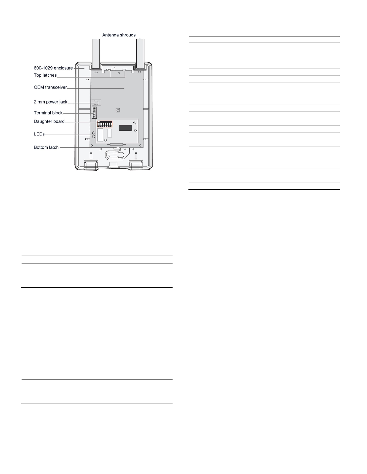
Figure 2: Installing Circuit Board
Indication
Green LED
Red LED
Powered up
On
Off
Communication with
daughter board
On
Flashing
Valid packet received
One flash off
Off or flashing
Problem
Action
OEM transceiver
module’s green and red
LEDs are off
1. Check that the transformer is
plugged in.
2. Check the transformer to
module wiring.
OEM receiver module’s
green LED is on and the
red LED is off
Check the daughter board
mounting.
Model
600-1046-95
Frequency
319.5 MHz
Compatibility
All 319.5 MHz sensors and 319.5 MHz
receivers
Current required (without daughter board)
Typical
45 mA
Maximum
100 mA
Voltage
8 to 15 VDC
Wireless range
1,000 feet (305 m) open air
Operating temperature
32 to 120°F (0 to 49°C)
Storage temperature
-30 to 140°F (-34 to 60°C)
Maximum relative
humidity
90% noncondensing
Dimensions
3.2 x 4.6 x 0.6 inches (8.1 x 11.7 x 1.5 cm)
Features
Antenna tamper, jam detect, wall tamper,
cover tamper
Optional items:
Enclosure
600-1029
USB daughter board
59-873
Repeater daughter
board
600-1031 or 600-1067
Stand-off
40-262
4. Connect DC power to the OEM transceiver module
using 2 mm power jacks (center positive) or connect flyleads to the terminal block as labeled on the board.
Specifications
LED Operation
Table 1 shows the LED indications for the OEM transceiver
module.
Table 1: OEM Transceiver Module LED Indications
Troubleshooting
The following table gives troubleshooting suggestions for the
OEM transceiver module.
Table 2: OEM Transceiver Module Troubleshooting
2 / 3 P/N 466-2236 • REV D • 7MAY18
Page 3

Regulatory Information
Manufacturer
UTC Fire & Security Americas Corporation, Inc.
2995 Red Hill Ave, Costa Mesa, CA 92626 USA
FCC / IC
compliance
This device complies with FCC Rules Part 15.
Operation is subject to the following two
conditions:
1. This device may not cause harmful
interference.
2. This device must accept any interference that
may be received, including interference that may
cause undesired operation.
Changes or modifications not expressly approved
by UTC Fire & Security can void the user’s
authority to operate the equipment.
FCC: B4Z-903A3-TCVR
IC: 867A-903A3TCVR
This device complies with Industry Canada
license-exempt RSS standard(s). Operation is
subject to the following two conditions:
(1) this device may not cause interference, and
(2) this device must accept any interference,
including interference that may cause undesired
operation of the device.
Cet appareil est conforme aux normes RSS
exemptes de licence d'Industrie Canada. Le
fonctionnement est soumis aux deux conditions
suivantes: (1) cet appareil ne doit pas causer
d'interférences, et (2) cet appareil doit accepter
toute interférence, y compris les interférences
pouvant provoquer un fonctionnement indésirable
de l'appareil.
California code
This product cannot be sold in the state of
California if used to receive fire signals (per
section 208-g, Chapter 1.5 Construction Materials
and Equipment Listings, Title 19, California Code
of Regulations
(http://osfm.fire.ca.gov/pdf/fireengineering/bml/t-
19.pdf)).
P/N 466-2236 • REV D • 7MAY18 3 / 3
Contact information
www.utcfireandsecurity.com or www.interlogix.com
For customer support, see www.interlogix.com/customer-support
© 2018 UTC Fire & Security Americas Corporation, Inc.
Interlogix is part of UTC Climate Controls & Security, a unit
of United Technologies Corporation. All rights reserved.
May 7, 2018
 Loading...