

Page 1
*Ài
>ÀÞÊ
£äÉÓÎÉ
'RRU:LQGRZ/RQJ
/LIH'RRU:LQGRZ
6HQVRUV
ITI Part Nos. 60-362 & 60-641
Document Number: 466-1022 Rev. D PRELIMINARY
October 2000
Product Summary
The Door/Window Sensor (60-362) and Long Life Door/
Window Sensor (60-641) can be installed on doors, windows, or virtually anything that opens and closes. During
normal operation, the sensors transmit open (TRIP) and
close (RESTORE) signals to the panel. The sensors also
send a supervisory signal to the panel every 64 minutes.
Sensors transmit open and close signals to the panel when a
magnet (mounted near the sensor) is moved away from or
closer to the sensor.
The sensors are powered by a 3. 6-volt lithium batte ry.
Ìi
The Long Life Door/Window Sensor battery ca nnot be
replaced by installers or users. If you receive a low
battery report, you must return the sensor to ITI for
replacement.
Tools Needed
8867g01a.ds4
ÃÌ>>ÌÊÃÌÀÕVÌÃ
q Remove the internal reed switch not being used.
q Avoid mounting sensors in areas with a large quantity
of metal or electrical wiring, such as a furnace or utility
room.
q Avoid mounting sensors in areas where they will be
exposed to moisture.
q Avoid mounting sensors in locations where the operat-
ing temperature (10° to 120° F) will be exceeded.
1/"
Do not remove the jumper from the Long-Life Door/
Window Sensor circuit board ! The sensor ca nnot work
without the jumper.
Installation
1/"
You must be free of all sta tic ele ctri ci ty w h en h and lin g
electronic compone nts. Touc h a groun ded, bare m etal
surface before touching a circuit board or wear a
grounded wrist strap.
q #6 flathead screws or 18-gauge brads
q Screwdriver or brad driver
q Small wire cutters
q Sensor and magnet spacers (opti o nal )
Installation Guidelines
q Keep all sensors within 100 feet of the panel.
q Mount the sensor on the door frame and the magnet on
the door. If the sensor is to be used on double doors,
mount the sensor on the least used door and the magnet
on the other do or.
q Mount sensors with screws or brads, not double-sided
tape.
q Place sensors at least 5 inches above the floor to avoid
damaging them.
q Use spacers (not included) to keep sensor s and magnets
away from metal or metallic surfaces such as foil wallpaper.
Door/Window Sensor Spacers
White: ITI Part #60-189
Brown: ITI Part #60-191
Magnet Spacers
White: ITI Part #60-188
Brown: ITI Part #60-190
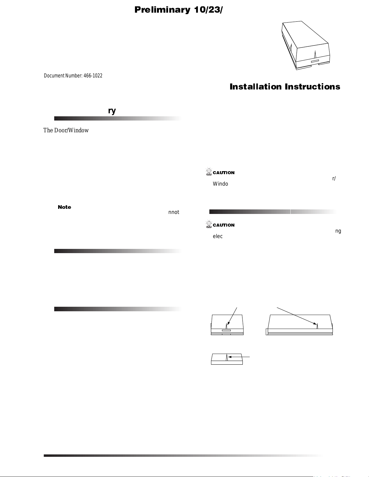
1. Decide if the sensor shou ld be mounted horizontally o r
vertically by locating the alignment marks on the sensor and magnet plastic (see Figure 1.)
The marks indicate reed switch locations. Each sensor
uses only one of the two switches. You will remove the
unused one in step 4.
ALIGNMENT MARKS
SENSOR END VIEW SENSOR SIDE VIEW
ALIGNMENT MARK
MAGNET
Figure 1. Alignment marks
2. Remove the sensor cover by squeezing the cover ends
firmly to release the tab on the cover from the slot on
the sensor base.
3. Remove the circuit board from the sensor base by pulling back the plastic tab and lifting the battery to release
the circuit board.
8867G03A.DS4
Door/Window & Long Life Door/Window Sensors
1
Page 2
Connecting External Switches
TA M PER S W ITC H
TERMINALS
CIRCUIT
BOARD
H O LD ING TAB
REED SW ITCHES
8867G 05A .D S F
3.6 V O LT
1/2 A A B A TTE R Y
M O D E L 60-362
JUM PER
TA M PER S W ITC H
TERMINALS
CIRCUIT
BOARD
H O LD ING TAB
REED SW ITCHES
3.6 VOLT AA BATTERY
8867G 04C .D S F
M O D E L 60-641
*Ài>ÀÞÊ£äÉÓÎÉ
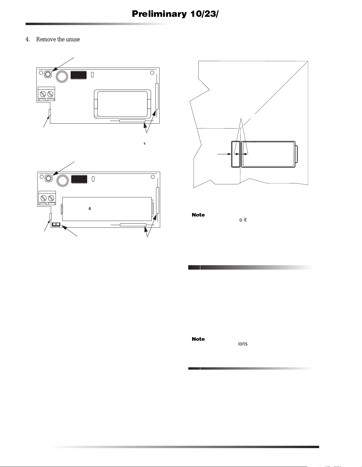
4. Remove the unused reed switch, clipping the leads as
close to the board as possible (see Figure 2.)
6. Remove the magnet from its base. Mount the magnet
base no more than 3/8 inches away from the sensor
base (see Figure 3). Replace magnet cover.)
ALIGNMENT MARKS
MAGNET
DOOR
Figure 3. Mounted Sensor and Magnet
SENSOR
DOOR FRAME
8867G02A.DS4
5. Mount the sensor base with screws or brads. Use spac-
Figure 2. Door/Window Sensor Circuit Boards
ers to compensate for metal surfaces or height variations.
Ìi
Mount the magnet so it won’t interfere with door or
window openings. Do not use two-sided tape.
7. Reattach the circuit board to the sensor base.
8. Reattach the sensor cover to the sensor base.
Connecting External Switches
Door/window sensors can be connected to either normally
open (close on alarm) or normally closed (open on alarm)
external switches. Wire multiple, normally closed switches
in series. Wire multiple, normally open switches in parallel.
Do not attempt to use the built-in reed sw itches and an
external switch on the same door/window sensor. For high
security installations, always remove both reed switches
when connecting an external switch to the sensor terminals.
Ìi
In UL listed i ns tallations, only the normally cl os ed configuration can be used.
Materials Needed
q Hermetically sealed external switches (sealed reed
switch) that supply a minimum 25 0-millisecond open
or closure on alarm.
q Stranded 22 -gauge wire.
q Installation Guidelines
q Do not use solid core wire.
q Do not use mechanical switches.
2
Door/Window & Long Life Door/Window Sensors
Page 3

*Ài>ÀÞÊ£äÉÓÎÉ
Programming
q If you are connecting a remote device to a door/win-
dow sensor, do not use the built-in reed switches.
q Do not connect fast pulse devices (such as Window
Bugs) to door/window sensors.
q Do not use more than 25 fe et of 22-gauge, strande d
wire in any wire run.
q Do not use more than 6 feet of untwisted wire in any
wire run.
q Do not connect more than five switches or more than
one alarm screen to a door/window sensor.
q Do not run wires parallel to electrical wires. If you
can’t avoid a parallel wire run, keep it at least 18 inches
away from electrical wiring.
q If necessary, you may cross electrical wires at a 90
degree angle.
Programming
The following steps describe the general guidelines for programming (learning) the sensor into panel memory. Refer to
the specific panel installation instructions or reference manual for complete programming details.
1. Set the panel to the program mo de.
2. Proceed to the LEARN SENSORS menu.
3. Select the appropriate sensor group and sensor number assignments.
4. Set the external switch (if one is connected) in the
alarm condition (open for normally closed circuits;
closed for normally open circuits).
5. Trip th e sens or’ s t amper switc h by removin g th e sens or cover .
6. Exit program mode.
7. Place the cover back on the sensor.
Testing
When the power-saver feature is on, the sensor transmits
only half the usual number of d ata rou nds when tr ipped. Fo r
example, during a dealer sensor test you normally expect to
hear up to 8 data rounds. When the power-saver feature is
on, you may hear only up to 4 data rounds.
To be sure the sensor has acceptable transmitting range to
the panel, leave the sensor undisturbed in the closed (nonalarm) condition for 5 minutes before tripping it for testing.
This gives the sensor enough time to turn off the powersaver feature so you can get accurate sensor test results.
Specifications
Operating Temperature Range: 0° to 120° F.
Compatibility: All Learn Mode panels
Power Source: 1/2 AA 3.6-volt lithium battery for 60-362 ,
AA 3.6-volt lithium battery for 60-641
Transmit Range: At least 500 feet, open air
Notices
FCC Part 15 Information to the User
Changes or modifications not expressly approved by Interactive Technolo-
gies, Inc. can void the u ser’s authority to operate the equipment.
FCC Part 15 Class A
This equipment has been tested and found to comply with the limi ts for a
class A digital device, pursua nt to part 15 of the FCC rules. These limi ts
are designed to provide reasonable protection against harmful interference
when the equipm ent is operated in a commercial envi ronment.
This equipment gene ra tes, uses, and can radiate radi o frequency energy
and, if not install ed and used in accordance with the ins truction manual,
may cause harmful interference to radio communications. Operation of
this equipmen t in a residential ar ea is likely to cause ha rmful interferen ce
in which case users will be required to correct the interference at their own
expense.
The following steps describe the general guidelines for testing the sensor. Refer to the specific panel installation
instructions or reference manual for complete testing
details.
1. Set the panel to the dealer senso r tes t mode.
2. Trip the sensor.
3. Listen for interior siren beeps to indicate how many
rounds the panel receives from the sensor. You should
hear 6 to 8 beeps.
Notes on Testing the LongLife Door/ Window Sensor
The Long Life Door/Window Sensor has a built-in powersaver feature that turns on automatically when the sensor is
tripped more than once, within a 4-1/4 minute time period.
Door/Window & Long Life Door/Window Sensors
FCC Part 15 Class B
This equipment has been tested and found to comply with the limi ts for a
Class B digital device, pursua nt to part 15 of the FCC Rules. These lim i ts
are designed to provide reasonable protection against interference in a residential install ation.
This equipment gene ra tes, uses, and can radiate radi o frequency energy
and, if not install ed and used in accordance with the ins tructions, may
cause harmful interfe rence to radio communi ca tions. However, there is no
guarantee that inte rference will not occur in a particular instal la tion.
If this equipment doe s cause harmful interfe rence to radio or television
reception, which can be determined by turning the equipment off and on,
the user is encourage d to try to correct the inte rference by one or more of
the following measures:
q
Reorient or reloca te the receiving an t enna.
q
Increase the separation between the equipment and receive r.
q
Connect the affected equipment and the pa nel receiver to separate
outlets, on different branch c irc ui ts.
q
Consult the dealer or an experienced radio /TV technician fo r hel p.
3
Page 4

Notices
*Ài>ÀÞÊ£äÉÓÎÉ
4
Door/Window & Long Life Door/Window Sensors
 Loading...