

Page 1
60
60
60
PET Immune SAW PIR Motion Sensors Installation Sheet
• Supervisory signals transmitted every 64 minutes to the
Description
This is the Installation Sheet for SAW PIR and PET Immune
Motion Sensors. See Table 1.
Table 1: Motion Sensors
-807-95R Pet Immune SAW PIR Motion Sensor
-807-01-95R
-807-02-95R
A motion sensor (passive-infrared or PIR) detects movement
within a specific area by sensing the infrared energy emitted
from a body as it moves across the sensor’s field of view.
When this motion is detected, the sensor transmits an alarm
signal to the control panel.
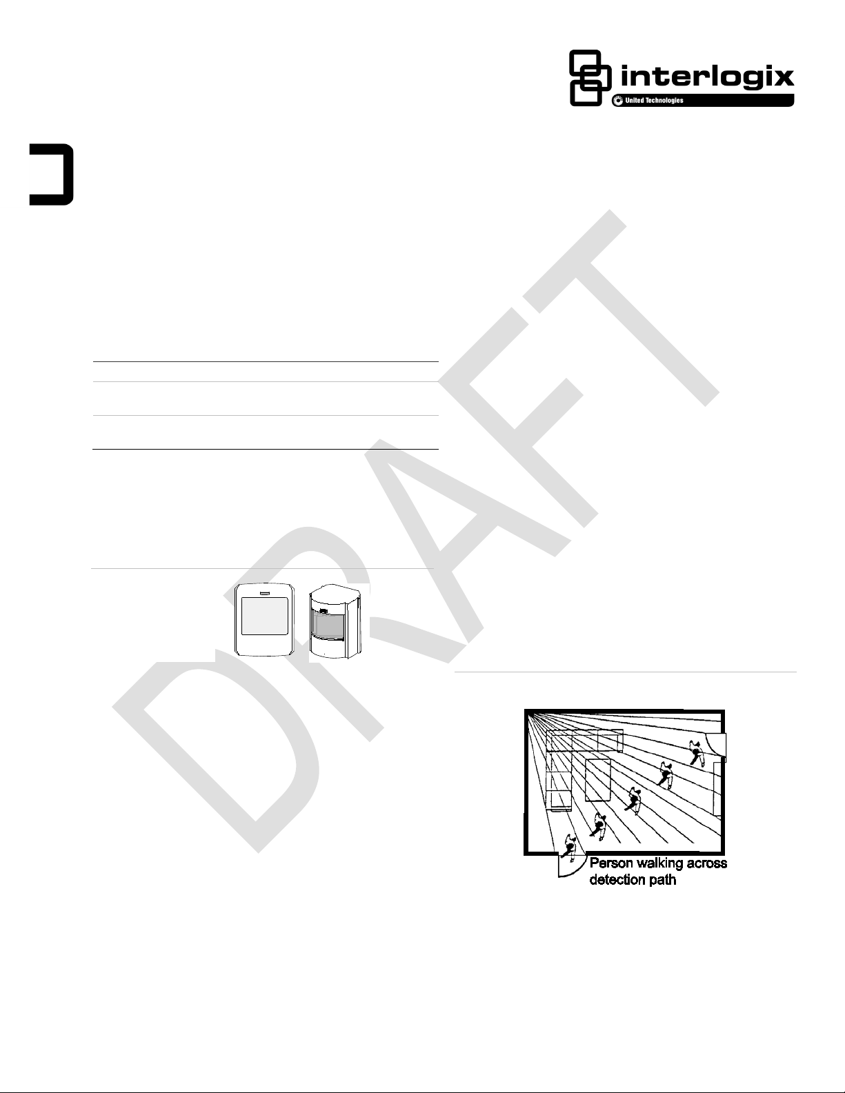
Figure 1: Pet Immune SAW PIR Motion Sensors
Pet Immune SAW PIR Motion Sensor with Lithium
Battery.
Pet Immune SAW PIR Motion Sensor with 1.5 V
Lithium Batteries.
control panel.
• Sensor low battery reports (trouble) to the control panel.
• Field-selectable sensitivity options.
Installation
Installation Guidelines
• Temporarily place the sensor in its intended mounting
location. Program and final test the sensor befor e
permanently mounting it.
• If possible, locate sensors within 100 ft. (30.5 m) of the
panel. While a transmitter may have a range of 500 ft.
(152 m) or more out in the open, the environment at the
installation site can have a significant effect on
transmitter range. Sometimes a change in sensor
location can help overcome adverse wireless conditions.
• The recommended mounting height is 7 1/2 ft.
Use these motion sensors to protect locations where
door/window sensors are impractical or not needed. For
example, use a motion sensor to protect large areas or open
floor plans. Motion sensors also provide backup protection for
door/window sensors.
The Pet Immune SAW PIR 60-807 utilizes advanced signal
processing, a new custom designed lens, and a new custom
designed sensing element. The combination of these
improvements provides false alarm immunity for pets with a
combined weight of up to 40 pounds while still providing
superior human catch performance.
These wireless motion sensors include the following features:
• 35 by 40 ft. (10.6 m by 12 m) coverage area.
• Three minute transmitter lockout time after an alarm that
helps extend battery life.
• Cover-activated tamper (optional wall-activated tamper is
included).
• Position the sensor to protect an area where an intruder
would be most likely to walk across the detection pattern
See Figure 2.
Figure 2: Overhead Detection Path
• Mount the motion sensor on a rigid surface which is free
from vibrations.
• Do not mount the sensor near duct work or other large
metallic surfaces which may affect the RF signals (see
RF Testing). Actual acceptable transmitter range should
be verified for each installation.
P/N 466-1725 • RevD.07 • 25Feb14 1 / 6
Page 2
• Mount the sensor permanently on a flat wall or in a
corner. Do not set it on a shelf.
• Windows should be closed in any area which has an
armed motion sensor.
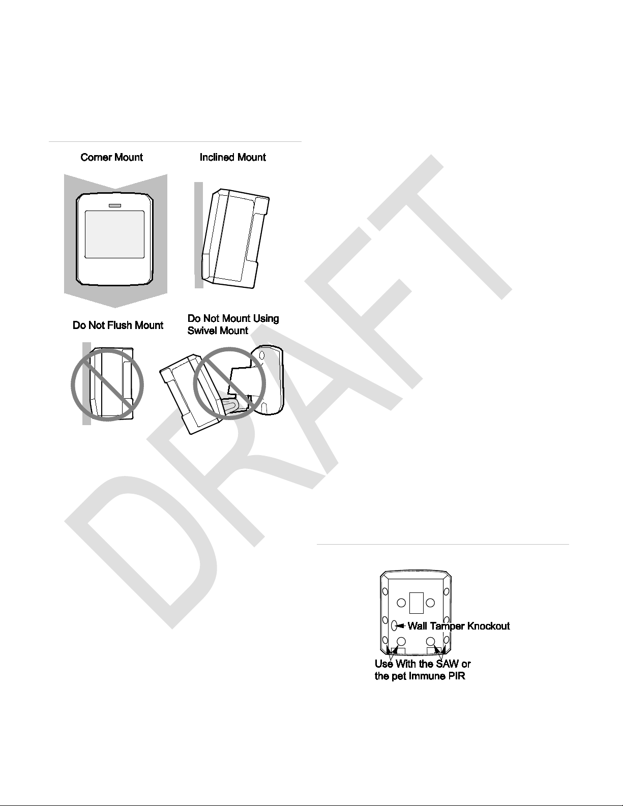
• The sensor must be incline-mounted at a mounting
height of 7.5 ft. See Figure 3.
Figure 3: Wall Mount Options
Final Testing
Final testing should be done to verify radio signal integrity
and confirm control panel programming and response. The
actual transmitter range can be determined by performing a
sensor test as follows:
1. With the PIR temporarily mounted at its intended
location, remove the PIR from its mounting plate and
activate the tamper switch to start the walk test mode.
2. Replace the sensor in its mounting plate.
3. Place the control panel in Sensor test mode. Move
across the detection pattern until the sensor’s LED turns
on. STOP your motion.
4. Listen for the appropriate system response. Refer to the
specific panel installation manual for details on system
response. If the system does not respond as expected,
proceed to the “Troubleshooting” section.
Mounting
The sensors must be incline-mounted on a wall surface or
incline-mounted in a corner at a mounting height of 7.5 ft.
(2.5 m).
• Room temperature must be kept between 60° and 120°F
(16° and 49° C).
• Position the sensor so it faces a solid reference point,
like a wall.
Programming
Refer to the panel documentation for information on
programming the sensor into the panel.
To Trip the Sensor
1. Set the panel to program mode.
2. Proceed to the Learn Sensors menu.
3. Remove the PIR from its mounting plate (activ at ing the
tamper switch).
To Mount the Sensor
1. Remove the mounting plate by depressing the button on
the top of the sensor body. With the opposite hand pull
the mounting plate away from the body of the sensor.
2 Punch out the mounting holes that best fit your
application. See Figure 3 for wall mount options.
3. See Figure 4 to determine which knockouts to use when
mounting the motion sensor. Use the lower-side holes
for corner mounting, or the lower-back holes for surface
mounting.
4. If wall-tamper functionality is desired, remove the walltamper knockout See Figure 4.
Figure 4: PIR Mounting Plate Knockouts
4. Select the appropriate sensor group and number .
5. Exit the panel’s programming mode.
6. Return the PIR to its mounting plate.
2 / 6 PET Immune SAW PIR Motion Sensors Installation Sheet
6. Mark the location of the required holes on the mounting
surface.
Page 3

7. Use wall anchors and screws to secure into place.
Attach the sensor to the mounting plate.
8. When testing is completed the PIR can be securely
attached to its mounting plate by screwing the smalle st
enclosed screw into the hole at the top of the mounting
plate.
Setting the Sensitivity
The PIR has two sensitivity settings (standard and high
sensitivity). The sensor is set to standard sensitivity at the
factory. This sensitivity is preferred for most applications and
provides the best immunity to false alarms.
Note: If the shorting jumper is not used or is placed
incorrectly, the sensor defaults to standar d sensitiv ity .
Figure 5: Sensitivity Pin Locations
Figure 6: Standard Sensitivity Setting
CAUTION: High sensitivity should only be used in
environments where the room temperature is very
stable.
1. Remove the mounting plate by depressing the button on
the top of the sensor body. With the opposite hand pull
the mounting plate away from the body of the sensor.
2. Remove the PIR cover by depressing the three tabs
3. Locate the sensitivity pins under the battery on the right
side of the PIR when looking at the front of the PIR.
4. To change to high sensitivity move the shorting jumper
to the pair of pins that are closer to the top of the PIR
See Figure 5.
5. Walk test the PIR to verify the sensitivity.
The difference between the two settings are indicated in
Figures 6 and 7.below.
Figure 7: High Sensitivity Setting
PET Immune SAW PIR Motion Sensors Installation Sheet 3 / 6
Page 4

60
60
60
Important information Regarding Sensitivity Settings
The sensitivity settings should be set as followed:
Standard Sense:
• Rooms < 25ft
• Pets < 40 pounds
High Sense:
• Rooms < 35ft
• Pets < 20 pounds
Testing
Walk Testing
Walk testing should be done to determine the sensor’s actual
coverage area. The edge of the coverage pattern is
determined by the first flash of the LED. This may change
slightly depending upon the sensitivity setting. Walk test the
unit from both directions to determine the pattern boundaries.
CAUTION: Excessive use of the walk test mode may
reduce battery life. Use only for initial setup and
maintenance testing.
1. Remove the sensor body from the mounted mounting
plate and then remount the body to activate the 60
second walk test mode.
2. Walk across the coverage pattern to determine the
coverage area, indicated by LED activation. Each
activation extends the walk test mode for an additional
60 seconds.
After 60 seconds without motion the walk test mode and the
LED will no longer activate when motion is detected.
Note: When the walk test mode has ended, an alarm can be
transmitted only after 3 minutes have passed since the
previous alarm. This 3 minute lockout time reduces
unnecessary RF transmissions in high traffic areas thereby
extending battery life.
Replacing the Batteries
When the system indicates the sensor has low batteries,
replace the batteries immediately. The sensors are powered
by the batteries shown in Table 2. Use only the batteries
indicated in Table 2 for the appropriate sensor. See the steps
listed after Table 2 for replacing the batteries.
Table 2: Battery Replacement
-807-95R Two AA Alkaline Batteries
-807-01-95R One AA Lithium Battery (#60-619).
-807-02-95R
Two 1.5 AA Lithium Iron Disulfide Batteries (#60-
931).
1. Remove the mounting plate by depressing the button on
the top of the sensor body. With the opposite hand pull
the mounting plate away from the body of the sensor.
See Figure 8.
2. Remove the PIR cover by depressing the three tabs.
See Figure 8.
3. Remove the old batteries and replace them with new
batteries as noted in Table 2 and Figure 8.
Note: Observe polarity when replacing the batteries. For
all units install the battery on the right side as shown in
Figure 8 with the positive end of the battery facing down
(near the tamper switch). For 60-807-95R and 60-80702-95R units with two batteries, install the second
battery on the left side with the positive end of the
battery facing up. See Figure 8.
If a battery is installed incorrectly the unit will not function
and the red LED will not light up. The sensor may be
damaged if a battery is installed incorrectly. For sensors
with two batteries, always replace both batteries.
4. Dispose of the batteries as required by local
requirements
5. Walk test the PIR to verify proper operation.
Note: When the battery is replaced, wait at least three
minutes after installing the battery before activating the
walk test mode.
Environment Testing
Figure 8: PIR Compon e nts, Battery Locations & Tamper Switch
Turn on all heating or air conditioning sources which would
normally be active during the protection peri od. Stand away
from the sensor and outside the coverage pattern and watch
for alarms. When testing the Pet Immune PIR also verify the
pets allowed in the coverage pattern do not trip the PIR.
Maintenance
At least once a year, the range and coverage should be
verified for proper operation. The end user should be
instructed to put the sensor in walk test mode and walk
through the far end of the coverage pattern to verify proper
detection.
4 / 6 PET Immune SAW PIR Motion Sensors Installation Sheet
Page 5

RF Frequency
Compatibility
Battery Type
Typical Battery Life
Operating
Temperature
Supervisory Interval
Relative Humidity
Storage Temperature
Range
Weight
Dimensions
(L x W x H )
RF
Compatibility
Battery Type
Typical Battery Life
Operating
Temperature
Supervisory Interval
Relative Humidity
Storage Temperature
Range
Weight
Dimensions
(L x W x H )
RF Frequency
Compatibility
Battery Type
Typical Battery Life
Operating
Temperature
Supervisory Interval
Relative Humidity
Storage Temperature
Range
Weight
Dimensions
(L x W x H )
Troubleshooting
Use the following guidelines if the system does not respond
correctly when the sensor final testing is conducted.
• Check programming and re-program sensor into panel if
necessary.
• Move the sensor to another location and test for correct
response.
• Check the mounting height and angle are according to
“Mounting” section.
To Relocate a Sensor
1. Test the sensor a few inches from the original position.
2. Increase the distance from the original position and
retest until an acceptable location is found.
3. Mount the sensor in the new location.
4. If no location is acceptable, test the sensor as described
below:
• Test a known good sensor at the same location.
• If the system does not respond, avoid mounting a sensor
at that location.
• If the replacement sensor functions, return the problem
sensor for repair or replacement.
Specifications
60-807-95R
319.5 MHz
Interlogix 319.5 MHz control panels/receivers
Two AA Alkaline Batteries
2 – 4 years at 68° F (20° C)
Range
0.3 lbs (0.136 kg)
32° to 110°F (0° to 43°C) Non-pet
applications
60° to 110°F (16° to 43°C) Pet applications
64 Minutes
0 – 90% non-condensing
-30 to 140°F (-34 to 60°C)
2.875 x 2.375 x 1.875 in.
(7.303 x 6.033 x 4.763 cm)
60-807-01-95R
Frequency 319.5 MHz
Interlogix 319.5 MHz control panels/receivers
Range
0.3 lbs (0.136 kg)
60-807-02-95R
319.5 MHz
Interlogix 319.5 MHz control panels/receivers
Range
0.3 lbs (0.136 kg)
One AA Lithium Battery
Interlogix part #60-619
4 – 6 years at 68° F (20° C)
32 to 120°F (0 to 49°C) Non-pet applications
60 to 120°F (16 to 49°C) Pet applications
64 Minutes
0 – 90% non-condensing
-30 to 140°F (-34 to 60°C)
2.875 x 2.375 x 1.875 in.
(7.303 x 6.033 x 4.763 cm)
Two 1.5V AA Lithium Iron Disulfide Batteries
(Interlogix part # 60-931, six pack of
batteries).
Note: Use only AA 1.5 Volt Lithium Iron
Disulfide batteries (part # 60-931) with this
product. Do not substitute any other
brand/type of batteries.
2-5 years at 68° F (20° C)
32 to 120°F (0 to 49°C) Non-pet applications
60 to 120°F (16 to 49°C) Pet applications
64 Minutes
0 – 90% non-condensing
-30 to 140°F (-34 to 60°C)
2.875 x 2.375 x 1.875 in.
(7.303 x 6.033 x 4.763 cm)
PET Immune SAW PIR Motion Sensors Installation Sheet 5 / 6
Page 6

Regulatory Information
This equipment has been tested and found to comply with the
limits for a Class B digital device, pursuant to Part 15 of the
FCC Rules. These limits are designed to provide reasonable
protection against harmful interference in a residential
installation.
This equipment generates,uses and can radiate radio
frequency energy and, if not installed and used in accordance
with the instructions, may cause harmful interference to radio
communications. However, there is no guarantee that
interference will not occur in a particular installation.
If this equipment does cause harmful interference to radio or
television reception, which can be determined by turning the
equipment off and on, the user is encouraged to try to correct
the interference by one or more of the follow ing mea sure s:
• Reorient or relocate the receiving antenna.
• Increase the separation between the equip ment and
receiver.
• Connect the equipment into an outlet on a circuit
different from that to which the receiver is connected.
• Consult the dealer or an experienced radio/TV technician
for help.
Changes or modifications not expressly approved by UTC
Fire and Security could void the user’s authority to operate
the equipment.
This device complies with Industry Canada licence-exempt
RSS standard(s). Operation is subject to the following two
conditions: (1) this device may not cause interference,and (2)
this device must accept any interference, in clud ing
interference that may cause undesired operation of the
device.
© 2014 United Technologies Corporation. Interlogix is part of
UTC Building and Industrial Systems, a United Technologies
Corporation. All rights reserved. The Product Name and logo
are trademarks of United Technologies. Other trade names
used in this document may be trademarks or registered
trademarks of the manufacturers or vendors of the respective
products.
Limitation of Liability
To the maximum extent permitted by applicable law, in no
event will Interlogix be liable for any lost profits or business
opportunities, loss of use, business interruption, loss of data,
or any other indirect, special, incidental, or consequential
damages under any theory of liability, whether based in
contract, tort, negligence, product liability, or otherwise.
Because some jurisdictions do not allow the exclusion or
limitation of liability for consequential or incidental damages
the preceding limitation may not apply to you. In any event
the total liability of Interlogix shall not exceed the purchase
price of the product. The foregoing limitation will apply to the
maximum extent permitted by applicable law, regardless of
whether Interlogix has been advised of the possibility of such
damages and regardless of whether any remedy fails of its
essential purpose.
Installation in accordance with this ma nual , appli cab le code s,
and the instructions of the authority having jurisdiction is
mandatory.
While every precaution has been taken during the
preparation of this manual to ensure the accuracy of its
contents, Interlogix assumes no responsibility for errors or
omissions.
Cet appareil est conforme avec Industrie Canada exempts de
licence standard RSS (s). Son fonctionnement est soumis
aux deux conditions suivantes: (1) cet appareil ne doit pas
provoquer d'interférences et (2 ) cet appareil doit accepter
toute interférence, y compris celles pouvant causer un
mauvais fonctionnement de l'appareil.
In accordance with FCC requirements of human exposure to
radiofrequency fields, the radiating element shall be installed
such that a minimum separation distance of 20 cm is
maintained from the general population.
FCC: B4Z-680F-PIR
IC: 1175C-680PIR
This Class B digital apparatus complies with Canadian ICES3B.
Cet appareil numérique de la classe B est conforme à la
norme NMB-3B du Canada.
Contact Information
For general information, see www.interlogix.com. For
customer/technical support, see
www.interlogix.com/customer-support
8889.
or call +1 855 286
6 / 6 PET Immune SAW PIR Motion Sensors Installation Sheet
 Loading...