

Page 1
6540UPIW-OEM
6’7” 13’1” 19’8”
26’2”
32’9”
40’0”
2m
6’7”
2m 4m 6m 8m 10m 12m
Long Range
Medium Range
Short
Range
2
Top
Cover
100 lb Pet Immune Wireless Motion Detector Sensor
Product Introduction
The 6540PIW100 Pet Immune Wireless Motion Detector Sensor has a
brand new range of volumetric motion sensor using a Fresnel lens, PIR
element and digital signal processing. This product complies with
UL639. It is suitable for indoor use in residential environments. For the
consumer, it builds value in meeting security needs with respecting
budgets. Quick to install and comes with a stylish low profile design. It
provides detection for a variety of ranges, including up to 360 degrees
of coverage for ceiling mount applications. It even has an option setting
for smart pet immunity up to 100lbs / 45kg, making this product all the
more attractive. This product delivers easy solutions for installers being equipped with flexible installation heights and optional mounting
bracket which are ideal for your security solution.
This wireless product works in conjunction with your wireless Control
Panel, providing a local indication.
About This Guide
This User Guide describes how to install, the operation and
maintenance of this product. The User Guide is organized as you intent
to use this product with step by step instructions.
Keep this document in a handy location and refer to it when you have
questions about this product and its functions and features. Reading
this guide is the only way to learn how to use your product wisely and
to know how to react in the event of an alarm.
1. General Information
Passive infrared (PIR) motion sensor technology provides one of the
most reliable and cost effective methods for protecting spaces in
homes, offices, or industrial facilities. PIR motion sensors sense
temperature contrasts between a relatively stable background and
hotter or colder objects moving across their fields of view. The sensors
emit no energy of their own, they merely
see
infrared images.
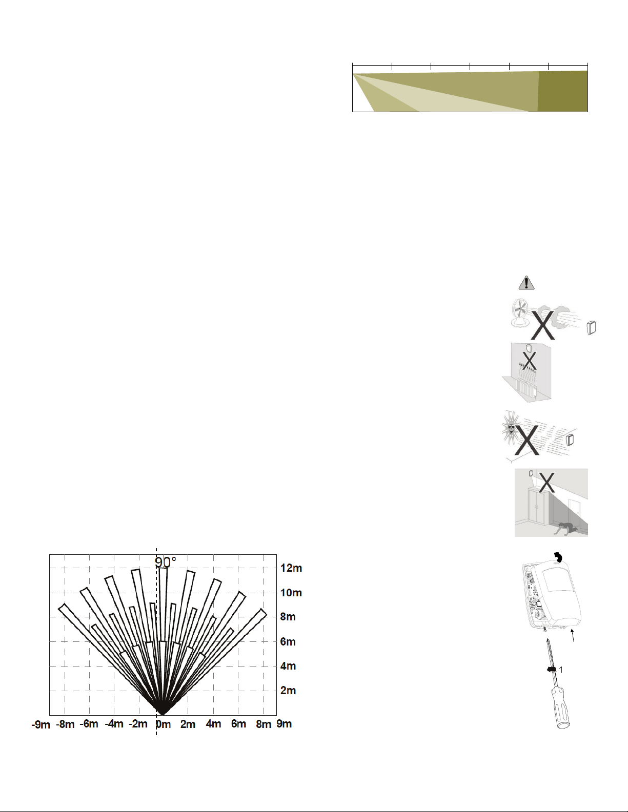
This product uses a Fresnel lens, PIR sensor element and digital signal
processing. The Fresnel lens focuses the 90
o
viewing range onto the
PIR sensor element through 24 lenses grouped into short, medium and
long range viewing. See picture below.
From a side view, the PIR detection range shows overlapping coverage
to ensure complete range detection. As shown here.
UTC. All Rights Reserved. 1 P/N 0000000 – Rev. A – 06 Nov 12
With all single lens Motion Detectors, it cannot see directly underneath
the device. Therefore mounting the device higher and angling down
maybe preferred.
The digital signal processing translates the heat signatures into
movement detection within the viewing range. Based on these
signatures the electronics determines the different between pets and
humans. To ensure a 100 lb / 45 kg pet can be detected versus a
person of the same weight, the motion detector uses a 4-pulse
algorithm, twice the industry norm.
2. Mounting Guideline
The technology used in these detectors
resists false alarm hazards. However,
avoid potential causes of instability
such as:
o Direct sunlight on the detector.
o Heat sources within the
detector field of view.
o Strong draughts onto the
detector.
o Large animals within the
detector field of view. (except for
pet immune version)
o Obscuring the detector field of
view with large objects, such as
furniture.
Not suitable for outdoor use.
3. Mounting the Sensor
A. Unscrew the base screw on the
detector until loose. The screw can be
retained in the product to secure
cover when complete with installation.
B. Lift detector cover out from the base
and off the lugs at the top.
C. Loosen the PCB lock screw and
remove the electronic assembly to
gain access to the case mounting
holes. Please use the battery
terminals as a hand hold in removing
the electronics.
D. Locate the base on the wall between
4.1 and 10 ft (1.5 - 3.1 m) from the floor.
Recommended height is 2 m / 6’ 7”. For flat wall mounting
use a minimum of 2
screws in positions A. For corner
Page 2
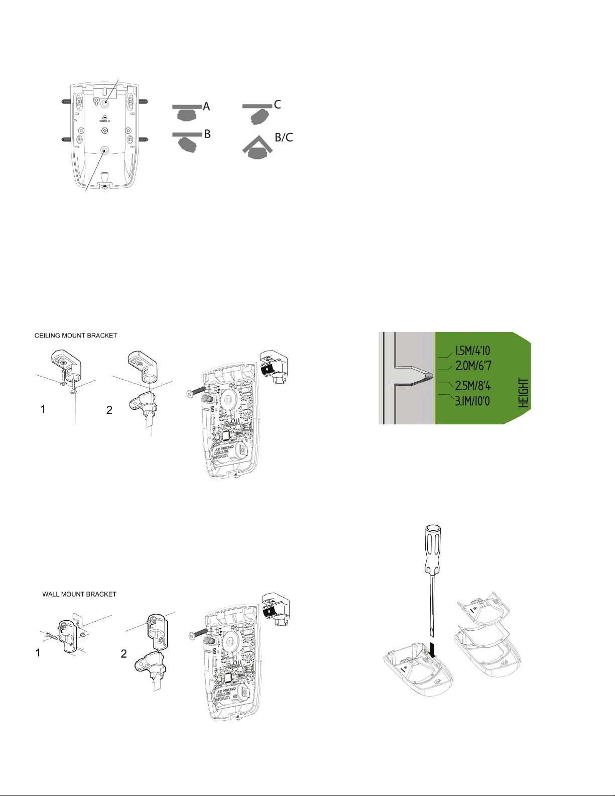
mounting use screws in positions B and/or C. Drill holes in
A
A
C
C
B
B
3
3
the base in provided screw locator.
E. An optional swivel mount bracket is available, 6545-BP. The
swivel bracket is used to adjust precisely the motion sensor’s
viewing field. The swivel bracket mounts to the product on the
top rear side for ceiling and wall mounts.
For ceiling mount, (1) position the ceiling bracket base and
secure properly to the ceiling. (2) Insert the swivel into the
base and (3) secure with screw through the product’s swivel
mount. With screw partially inserted make minor adjustments
to sensor’s view angle and secure.
1. Select the desired jumper settings. See the Jumper Adjustment
(1) – switch settings section for more information.
2. Add masking labels if required (see next section for an
example).
3. For ceiling mount applications that require a 90° coverage use
the optional swivel-mount bracket (Part Number: 6545U-BP).
4. Replace cover and tighten the screw in the base.
Note: ensure the battery is inserted properly and/or the battery pull
tab is removed to activate the product. See the Installing / Replacing
Batteries section for more information.
4. Sensor Setup & Jumper Selections
This sensor has two mechanical adjustment and three jumper switches
to aid in your application. After selecting your mounting location within
the room, it’s time to optimize the sensor.
Mechanical Adjustments (1) – Mounting Height
Located on the left side beneath the tamper spring is a PCB legend for
mounting height adjustment. Loosen the PCB mounting screw by
turning counterclockwise so that PCB may slide up and down. Use the
plastic pointer, locate your mounting height and tighten the PCB screw.
By selecting the proper height maximizes the sensors range and
viewing area.
Mechanical Adjustment (2) – Viewing Range
This adjustment allows the sensor’s viewing area to be limited into a
For wall mount, (1) position the wall bracket base and secure
properly to the ceiling material. First insert the top screw
partially into the wall so the screw head can be inserted into
vertical curtain, removing short-range scanning, removing long-range
scanning or any combinations that suits the application. If you know
the desired scanning zone(s) then add masking to the inside surface of
the Fresnel lens as shown below.
the keyhole opening. Insert second screw into the lower
mounting hole. (2) Insert the swivel into the base and (3)
secure with screw through the product’s swivel mount. With
screw partially inserted make minor adjustments to sensor’s
view angle and secure.
Note: left to right: full range, short range removed and ½ vertical range
To complete the installation…..
removed.
UTC. All Rights Reserved. 2 P/N 0000000 – Rev. A – 06 Nov 12
Page 3

Power ON
Input
Opt 2
Opt 1
(defaul t)
Walk Te s t
ON
OFF
(defaul t)
Pulse
CNT 2
CNT 4
(defaul t)
+
-
o The detector turns on with a 3V battery on the board. Remove
the battery pull tab and/or ensure the battery is installed per the
plus and minus signs located on the PCB white legend.
o At power up, the detector’s Status LED blinks for 60 seconds
with 1Hz frequency or 60 times. During this time, learn mode,
the detector sets its internal parameters according to
surrounding environment.
o RF Status LED blinks 3 times, once per second and waits for next
2 seconds. This indicates the detector is looking for control
panel to pair with i.e. enrollment.
o The RF Status LED turns OFF after 2 minutes or after enrolling
with a control panel.
Jumper Adjustment (1) – switch settings.
There are three (3) jumpers switches located on the Printed Circuit
Board in the upper left corner. These jumpers assist in setup the device
and its operation. Jumper Switch definitions:
Input – reserved for future features – not used.
Walk Test – used to disable the wireless alarm to the control
Pulse – selects the PIR sensitivity. Default is 100 lb pet
panel. Default is OFF.
immunity.
o If the battery is removed after enrollment into a control panel,
this enrollment sequence is skipped at the next power up. The
detector is already enrolled.
Normal Mode
o In normal mode of operation the Status LED remains OFF and
PIR sensor remains in power saving mode which increases the
battery life.
o The Sensor wakes upon the motion detection in the field of view
and the algorithm starts analyzing the signature of the heat
source movement.
o Once motion is detected in the field of view, the PIR status LED
turns ON for 2 seconds and sends the alarm signal to the
control panel using wireless message(s).
o Status LED remains ON as long as motion is detected in field of
view.
o Status LED turns OFF after two seconds when motion in no
longer detected in the field of view.
6. Installing / Replacing Battery
This detector comes with one battery preinstalled. When you need to
replace the battery, use the following procedure. Be sure the device is
mounted to the wall and the cover is attached before performing this
procedure.
o Place the control panel into sensor test mode. Otherwise, an
alarm/tamper condition may be indicated.
o Remove the top cover body off the detector.
Product shipped with factory default settings.
To verify the device detects all the areas, set the Walk Test jumper to
the ON position. This allows you to walk in all areas of coverage to
ensure the device detects a person’s movement. Make mechanical
mounting adjustments as required to cover the open area.
Depending on the pets inside the house, the motion detector’s Pet
Immunity is adjustable between 50 lbs or 100 lbs. Move the Pulse
jumper to pulse count 2-position for 50 lbs and pulse count 4 for 100
lbs.
o Remove the old battery and dispose of it properly, as
recommended by the battery manufacturer.
o Install the new battery. Note the polarity shown in the battery
compartment.
5. Basic Operations
This detector is equipped with a learn-mode at startup and an intuitive
normal mode.
UTC. All Rights Reserved. 3 P/N 0000000 – Rev. A – 06 Nov 12
o Install the top cover onto the detector.
o Perform a sensor/RF test with the control panel. See “Error!
Reference source not found.
”.
Page 4

o When replacing the battery, use one of the following approved
brands, which can be purchased at your local hardware store:
− Duracell
− Energizer E91
Using a different battery can affect the detector operation detrimentally.
Constant exposures to high or low humidity may reduce battery life.
7. Adding to the Touch Screen
Each detector is programmed with a unique ID when manufactured.
The unique ID is enrolled into the control panel at the time of
installation, allowing the detector to communicate with that specific
control panel.
o From the Home screen, touch the Settings widget.
o At the keypad, enter the Installer’s keypad code (not the
customer’s Master keypad code).
o At the keyboard screen, enter your Technician Code and touch
Done.
o At the Installer Settings Menu, touch Sensors & Zones > Add a
Sensor/Zone.
o At the Locating Wireless Sensors screen, default the detector
and place it in Search mode (see section x).
The detector must not be paired with another Touch Screen. If it is, unpair it (refer to the TouchScreen Installation Manual).
o Touch Next. A Stop button appears on the screen and the
TouchScreen searches for the detector to be added. When the
TouchScreen finds it, a grayed icon appears.
o Fault the detector to pair it to the TouchScreen. Move hand over
the PIR Sensor.
o Touch Stop. The Wireless Sensors Located screen shows the
detector that was found and paired.
o Touch Next. The Configure Wireless Sensors screen shows an
icon for the detector that was found.
o Touch the sensor icon to configure the detector. The Add
Sensor/Zone Modify screen appears.
o When the detector is configured properly, touch Next. The Add
Sensor/Zone Modify screen appears.
o To modify any text field on the TouchScreen, such as the Zone
Label, touch the field to display a keyboard. Then use the
keyboard to enter your changes and touch Done to save your
changes.
o As the detector is configured, the circle in the top-right of the
icon changes from:
o to .
o When the detector is configured properly, touch Next in the
Configure Wireless Sensors screen.
o If all sensors have not been configured, the Modify screen
appears for each sensor to let you review its details.
o Change the details as needed or touch Next to cycle through all
the sensors.
8. Testing the Detector
This detector has two test modes: Walk mode and RF Communication
Test.
Walk Test
This is a local test to determine the coverage area of the installation.
Enable Walk mode via the internal jumper. When enabled the detector
activates for detected motion by the detector’s LED indication. The
detector does not send an alarm message to the control panel. When
finished, place the Walk mode jumper back to the default setting.
Running the RF Communication Test
This section provides general guidelines for testing the detector with
the control panel. For complete testing details, refer to the specific
control panel documentation.
o Wait at least 5 minutes after installing the detector to test.
o Be sure the detector is normal operation.
o Set the control panel to sensor test mode to prevent an alarm
signal from being sent to the central-monitoring station if you
have a monitored system.
o To generate a test alarm, walk in the detector’s viewing range.
An alarm message is sent to the control panel. To generate a
tamper alarm, remove the detectors top cover. A tamper alarm
message is sent to the control panel.
o The control panel beeps and shows the number of RF packets
received.
o At the panel, exit sensor test mode.
9. Defaulting the Detector
This step should only be performed by a qualified service technician.
o Remove the detector’s top cover.
o Remove the battery.
o Press the enrollment switch in the RF circuit inside the detector
and hold until you replace the battery. Switch location shown
below.
o Replace the battery while still pressing the enrollment switch,
then release the switch. The RF LED flashes three times to signal
the detector is not paired with a control panel.
o Reinstall the front cover.
10. Viewing Zone Event History
To view event history:
A. Tap the Security widget on the Home screen.
B. Tap the History tab. The Zone Event History shows the event
history.
UTC. All Rights Reserved. 4 P/N 0000000 – Rev. A – 06 Nov 12
Page 5

00 µA (typically)
11. Disabling Zones
The system can bypass a zone, so the zone is not monitored when the
system is armed. This is useful when a sensor is being repaired. You
can only change the Bypass state of a zone when the system is
disarmed.
The system continues to log the activity of bypassed zones in the Event
History (see “View Zone Event History,” above).
To bypass a zone:
A. With the system disarmed, tap the Security app on the Home
screen.
B. Tap the Turn Zone Off button for the smoke alarm. The Turn Zone
Off button changes to Turn Zone On.
C. When the system is disarmed, the Security Status header shows
that some zones have been bypassed.
12. Troubleshooting
Detector does not power up properly or reports low battery
o Be sure the battery is fully seated within the battery
compartment and the polarity is correct.
o Check the battery voltage (3.0 VDC nominal).
Control Panel does not respond
o Use the 60-401 RF Sniffer to confirm that the detector is sending
messages for activation.
o Move or rotate the detector position.
o Be sure the detector is enrolled into the control panel properly.
o Be sure you are using a compatible control panel (see “Error!
Reference source not found.”).
Tamper condition does not restore
o Be sure the detector’s top cover is installed properly.
o Be sure there are no trouble indications at the detector.
o Be sure you are using a compatible control panel (see “Error!
Reference source not found.”).
If a tamper alarm occurs
o Be sure you are using a compatible control panel (see “Error!
Reference source not found.”).
o Be sure the control panel is in sensor test mode during sensor
testing.
Alarm/open condition does not restore
o Be sure the motion condition has cleared at the detector.
o Be sure you are using a compatible control panel (see “Error!
Reference source not found.”).
13. Specifications
Compatible panels -
Power One CR123 battery
Battery type 3.0 VDC lithium
Standby Current
Battery life 5 years (typically)
Sensor PIR thermal
Range 12 m / 40 ft @ 90o
RF Wireless Frequency 2.4 GHz
Audible alarm Control Panel Indication
Weight w/battery 0.20 lbs / 0.09 kg
Dimensions
Storage temperature -4 to 140°F (-20 to 60°C)
Operating environment 40 to 100°F (4.4 to 37.8°C)
Relative Humidity 10 to 95% non-condensing
3.94 x 2.52 x 1.50 in.
(100 x 64 x 38 mm)
14. Maintenance Tips
To keep your detector in good working order:
o Perform a RF Communication Test once a week.
o Never use detergents or solvents to clean the detector.
Chemicals can permanently damage or temporarily
contaminate the Fresnel lens.
o Avoid spraying air fresheners, hair spray, paint, or other
aerosols near the detector.
o Do not paint the detector. Paint may interfere with proper
sensor operation.
15. Regulatory Information
Manufacturer: UTC Fire & Security
WEEE Directive
2002/96/EC (WEEE directive): Products marked with this symbol cannot
be disposed of as unsorted municipal waste in the
European Union. For proper recycling, return this product to
your local supplier upon the purchase of equivalent new
equipment, or dispose of it at designated collection points.
For more information see: www.recyclethis.info.
RoHs Directive
2002/95/EC RoHS Compliant. Hereby, UTC Fire and Security declares
that this device does not contain lead, mercury, cadmium, hexavalent
chromium, polybrominated biphenyls (PBB) or polybrominated
depheny ethers (PBDE) in more than the percentage specified by EU
directive 2002/95/EC, except exemptions stated in EU directive
2002/95/EC annex.
UL Rating
ANSI/UL 639 Recognized
FCC Compliance
FCC ID: QPY-6540UPI-Z
IC: 8303B-6540UPI-Z
UTC. All Rights Reserved. 5 P/N 0000000 – Rev. A – 06 Nov 12
Page 6

The device complies with part 15 of the FCC Rules as well as Industry
Canada Rules and Regulations license-exempt RSS standard(s).
Operation is subject to the following two conditions: (1) This device may
not cause harmful interference, and (2) this device must accept any
interference received, including interference that may cause undesired
operation.
Conformité Réglementaire
Ce dispositif est conforme à la réglementation de la IC et (Partie 15) de
la FCC. Son fonctionnement est soumis à deux conditions : (1) ce
dispositif ne doit pas causer d’interférences nuisibles, et (2) ce dispositif
doit accepter toute interférence reçue, y compris les interférences
pouvant entraîner des conditions de fonctionnement indésirables.
WARNING: Changes to Section 15 – Regulatory Information is
strictly prohibited. Any changes or modification made to the product
without the permission of the manufacturer could void the user’s
authority to use this product.
16. Product Information
Disclaimer
This PIR Motion Detector is not a complete alarm system, but only a
part of. Therefore UTC Fire & Security does not accept any responsibility
or liability for any damage that is claimed to be a result of an incorrect
functioning of the PIR Motion Detector. UTC Fire & Security reserves the
right to change the specification without a prior notice.
Limitations of Security Products
Security products and alarm systems do not offer guaranteed
protection against burglary, fire, or other emergencies. They may fail to
warn for diverse reasons, including (but not limited to): power failure,
dead batteries, improper installation, coverage, coverage areas
overlooked during installation, defeat by technically sophisticated
intruders, component failure, or inadequate maintenance. Alarm
systems should be checked weekly to ensure that all devices are
working properly.
AN ALARM SYSTEM IS NOT A SUBSTITUTE FOR INSURANCE
Limited Warranty
Edwards is a brand of UTC Fire & Security. The manufacturer warrants
this product (except batteries) to be free from defects in material and
workmanship under conditions of normal use for a term of 3 years
from the date of manufacture.
During the warranty period, if a UTC Fire & Security product or any of its
components becomes defective, it will be repaired or replaced without
charge.
Out-of-warranty units will be repaired at the discretion of the
manufacturer or, if not, a card will be forwarded to the customer
suggesting a replacement unit and the cost of that unit.
This warranty does not apply to units which have been subject to
abuse, misuse, negligence or accident, or to which any modifications,
alterations or repairs have been made or attempted.
This warranty is extended only to the original purchaser of the smoke
alarm and may be enforced only by such person. During the warranty
period, if the alarm or any warranted components thereof becomes
defective, it will be replaced or repaired without charge at the
manufacturer’s discretion if returned in accordance with the following
instructions:
Obtain a Return Authorization Number by calling the number below,
then carefully pack it in a well padded and insulated carton and return,
postal charges prepaid to:
This product is manufactured by Edwards, A UTC Fire and Security
Company, 8985 Town Center Parkway, Bradenton FL 34202.
Return units to: UTC – Climate, Controls & Security
325 N Main St
Pittsfield, ME 04967
Phone: 1-207-487-3104
A note should be included advising the nature of the malfunction. Care
must be exercised in the proper packing of produc(s) returned under
this warranty as UTC Fire & Security will not be responsible for warranty
repairs to equipment damaged because of improper packing.
The above warranty is in lieu of all other express warranties, and
implied warranties of merchantability and fitness for a particular
purpose are limited in duration for a period of THREE years from the
date of manufacture. Under no circumstances shall manufacturer be
liable to the purchaser or any other person for incidental or
consequential damages of any nature, including without limitation
damages for personal injury or damages to property, and however
occasioned, whether alleged as resulting from breach of warranty by
manufacturer, the negligence of manufacturer or otherwise.
Manufacturer’s liability will in no event exceed the purchase price of the
product. Some states do not allow limitations on how long an implied
warranty lasts, or the exclusion or limitation of incidental or
consequential damages, so the above limitations and exclusions may
not apply to you. Unless a longer period is required by applicable law,
any action against manufacturer in
connection with this smoke alarm must be commenced within one
year after the cause of action has occurred.
No agent, employee or representative of the Manufacturer, nor any
other person is authorized to modify this warranty in any respect.
Repair or replacement as stated above is the exclusive remedy of the
purchase hereunder. This warranty gives you specific legal rights and
you also have other rights which vary from state to state.
End of document
UTC. All Rights Reserved. 6 P/N 0000000 – Rev. A – 06 Nov 12
 Loading...